EP3181998B1 - Lichtwellenleiter zur beleuchtung einer anzeigevorrichtung - Google Patents
Lichtwellenleiter zur beleuchtung einer anzeigevorrichtung Download PDFInfo
- Publication number
- EP3181998B1 EP3181998B1 EP15199765.7A EP15199765A EP3181998B1 EP 3181998 B1 EP3181998 B1 EP 3181998B1 EP 15199765 A EP15199765 A EP 15199765A EP 3181998 B1 EP3181998 B1 EP 3181998B1
- Authority
- EP
- European Patent Office
- Prior art keywords
- light guide
- light
- central part
- peripheral part
- light source
- Prior art date
- Legal status (The legal status is an assumption and is not a legal conclusion. Google has not performed a legal analysis and makes no representation as to the accuracy of the status listed.)
- Active
Links
Images


Classifications
-
- G—PHYSICS
- G02—OPTICS
- G02B—OPTICAL ELEMENTS, SYSTEMS OR APPARATUS
- G02B6/00—Light guides; Structural details of arrangements comprising light guides and other optical elements, e.g. couplings
- G02B6/0001—Light guides; Structural details of arrangements comprising light guides and other optical elements, e.g. couplings specially adapted for lighting devices or systems
- G02B6/0011—Light guides; Structural details of arrangements comprising light guides and other optical elements, e.g. couplings specially adapted for lighting devices or systems the light guides being planar or of plate-like form
- G02B6/0013—Means for improving the coupling-in of light from the light source into the light guide
- G02B6/0015—Means for improving the coupling-in of light from the light source into the light guide provided on the surface of the light guide or in the bulk of it
-
- G—PHYSICS
- G02—OPTICS
- G02B—OPTICAL ELEMENTS, SYSTEMS OR APPARATUS
- G02B6/00—Light guides; Structural details of arrangements comprising light guides and other optical elements, e.g. couplings
- G02B6/0001—Light guides; Structural details of arrangements comprising light guides and other optical elements, e.g. couplings specially adapted for lighting devices or systems
- G02B6/0011—Light guides; Structural details of arrangements comprising light guides and other optical elements, e.g. couplings specially adapted for lighting devices or systems the light guides being planar or of plate-like form
- G02B6/0081—Mechanical or electrical aspects of the light guide and light source in the lighting device peculiar to the adaptation to planar light guides, e.g. concerning packaging
- G02B6/0086—Positioning aspects
- G02B6/0088—Positioning aspects of the light guide or other optical sheets in the package
-
- G—PHYSICS
- G02—OPTICS
- G02B—OPTICAL ELEMENTS, SYSTEMS OR APPARATUS
- G02B6/00—Light guides; Structural details of arrangements comprising light guides and other optical elements, e.g. couplings
- G02B6/0001—Light guides; Structural details of arrangements comprising light guides and other optical elements, e.g. couplings specially adapted for lighting devices or systems
- G02B6/0011—Light guides; Structural details of arrangements comprising light guides and other optical elements, e.g. couplings specially adapted for lighting devices or systems the light guides being planar or of plate-like form
- G02B6/0033—Means for improving the coupling-out of light from the light guide
- G02B6/0035—Means for improving the coupling-out of light from the light guide provided on the surface of the light guide or in the bulk of it
-
- G—PHYSICS
- G02—OPTICS
- G02B—OPTICAL ELEMENTS, SYSTEMS OR APPARATUS
- G02B6/00—Light guides; Structural details of arrangements comprising light guides and other optical elements, e.g. couplings
- G02B6/0001—Light guides; Structural details of arrangements comprising light guides and other optical elements, e.g. couplings specially adapted for lighting devices or systems
- G02B6/0011—Light guides; Structural details of arrangements comprising light guides and other optical elements, e.g. couplings specially adapted for lighting devices or systems the light guides being planar or of plate-like form
- G02B6/0033—Means for improving the coupling-out of light from the light guide
- G02B6/005—Means for improving the coupling-out of light from the light guide provided by one optical element, or plurality thereof, placed on the light output side of the light guide
- G02B6/0053—Prismatic sheet or layer; Brightness enhancement element, sheet or layer
-
- G—PHYSICS
- G02—OPTICS
- G02B—OPTICAL ELEMENTS, SYSTEMS OR APPARATUS
- G02B6/00—Light guides; Structural details of arrangements comprising light guides and other optical elements, e.g. couplings
- G02B6/0001—Light guides; Structural details of arrangements comprising light guides and other optical elements, e.g. couplings specially adapted for lighting devices or systems
- G02B6/0011—Light guides; Structural details of arrangements comprising light guides and other optical elements, e.g. couplings specially adapted for lighting devices or systems the light guides being planar or of plate-like form
- G02B6/0033—Means for improving the coupling-out of light from the light guide
- G02B6/005—Means for improving the coupling-out of light from the light guide provided by one optical element, or plurality thereof, placed on the light output side of the light guide
- G02B6/0055—Reflecting element, sheet or layer
-
- G—PHYSICS
- G02—OPTICS
- G02B—OPTICAL ELEMENTS, SYSTEMS OR APPARATUS
- G02B6/00—Light guides; Structural details of arrangements comprising light guides and other optical elements, e.g. couplings
- G02B6/0001—Light guides; Structural details of arrangements comprising light guides and other optical elements, e.g. couplings specially adapted for lighting devices or systems
- G02B6/0011—Light guides; Structural details of arrangements comprising light guides and other optical elements, e.g. couplings specially adapted for lighting devices or systems the light guides being planar or of plate-like form
- G02B6/0081—Mechanical or electrical aspects of the light guide and light source in the lighting device peculiar to the adaptation to planar light guides, e.g. concerning packaging
- G02B6/0086—Positioning aspects
- G02B6/009—Positioning aspects of the light source in the package
-
- G—PHYSICS
- G02—OPTICS
- G02F—OPTICAL DEVICES OR ARRANGEMENTS FOR THE CONTROL OF LIGHT BY MODIFICATION OF THE OPTICAL PROPERTIES OF THE MEDIA OF THE ELEMENTS INVOLVED THEREIN; NON-LINEAR OPTICS; FREQUENCY-CHANGING OF LIGHT; OPTICAL LOGIC ELEMENTS; OPTICAL ANALOGUE/DIGITAL CONVERTERS
- G02F1/00—Devices or arrangements for the control of the intensity, colour, phase, polarisation or direction of light arriving from an independent light source, e.g. switching, gating or modulating; Non-linear optics
- G02F1/01—Devices or arrangements for the control of the intensity, colour, phase, polarisation or direction of light arriving from an independent light source, e.g. switching, gating or modulating; Non-linear optics for the control of the intensity, phase, polarisation or colour
- G02F1/13—Devices or arrangements for the control of the intensity, colour, phase, polarisation or direction of light arriving from an independent light source, e.g. switching, gating or modulating; Non-linear optics for the control of the intensity, phase, polarisation or colour based on liquid crystals, e.g. single liquid crystal display cells
- G02F1/133—Constructional arrangements; Operation of liquid crystal cells; Circuit arrangements
- G02F1/1333—Constructional arrangements; Manufacturing methods
- G02F1/1335—Structural association of cells with optical devices, e.g. polarisers or reflectors
- G02F1/1336—Illuminating devices
- G02F1/133602—Direct backlight
- G02F1/133606—Direct backlight including a specially adapted diffusing, scattering or light controlling members
-
- G—PHYSICS
- G04—HOROLOGY
- G04G—ELECTRONIC TIME-PIECES
- G04G17/00—Structural details; Housings
- G04G17/02—Component assemblies
- G04G17/04—Mounting of electronic components
- G04G17/045—Mounting of the display
-
- G—PHYSICS
- G04—HOROLOGY
- G04G—ELECTRONIC TIME-PIECES
- G04G9/00—Visual time or date indication means
- G04G9/0082—Visual time or date indication means by building-up characters using a combination of indicating elements and by selecting desired characters out of a number of characters or by selecting indicating elements the positions of which represents the time, i.e. combinations of G04G9/02 and G04G9/08
- G04G9/0094—Visual time or date indication means by building-up characters using a combination of indicating elements and by selecting desired characters out of a number of characters or by selecting indicating elements the positions of which represents the time, i.e. combinations of G04G9/02 and G04G9/08 using light valves, e.g. liquid crystals
-
- G—PHYSICS
- G02—OPTICS
- G02B—OPTICAL ELEMENTS, SYSTEMS OR APPARATUS
- G02B6/00—Light guides; Structural details of arrangements comprising light guides and other optical elements, e.g. couplings
- G02B6/0001—Light guides; Structural details of arrangements comprising light guides and other optical elements, e.g. couplings specially adapted for lighting devices or systems
- G02B6/0011—Light guides; Structural details of arrangements comprising light guides and other optical elements, e.g. couplings specially adapted for lighting devices or systems the light guides being planar or of plate-like form
- G02B6/0066—Light guides; Structural details of arrangements comprising light guides and other optical elements, e.g. couplings specially adapted for lighting devices or systems the light guides being planar or of plate-like form characterised by the light source being coupled to the light guide
- G02B6/0073—Light emitting diode [LED]
Definitions
- the present invention relates to a light guide for lighting a display device in a timepiece.
- the present invention relates to such a light guide used for lighting a liquid crystal display device.
- a display device such as a liquid crystal display cell
- Information displayed by a display device is difficult to read in low light conditions. This is why it was considered very early on to illuminate such display devices by means of a light source.
- the most rudimentary known solutions simply consist of placing a point light source such as a filament bulb or a light-emitting diode at the rear of the liquid crystal display device.
- a point light source such as a filament bulb or a light-emitting diode
- Such solutions are not satisfactory because they do not ensure homogeneous illumination of the display surface of the liquid crystal display device. Indeed, a more intense halo of light is perceptible by the user through the liquid crystal display device at the location where the point light source is located.
- a light guide is a component of limited thickness made of a transparent material, typically a plastic material, whose dimensions correspond substantially to those of the display device.
- liquid crystal to be illuminated and into which the light produced by at least one light source optically coupled with the light guide is injected.
- Optical microstructures called light extractors whose function is to extract uniformly over the entire surface of the light guide the light injected into the light guide by the light source are structured in at least one of the upper or lower surfaces of the light guide.
- the light guide is for example of generally parallelepiped shape and comprises an upper surface 2 and a lower surface 4 connected together by a lateral edge 6. It also comprises one or more holes 8 for its mounting on a support part (not shown) as well as a pair of tenons 10 for fixing a sheet of printed circuit 12 serving as a support for a point light source 14 such as a light-emitting diode.
- the light guide 1 comprises optical prisms 16 commonly called light extractors which, in the example shown in figure 1 , are structured in the upper surface 2 of the light guide 1. These light extractors 16 are intended to extract upwards the light injected into the light guide 1 by the point light source 14 optically coupled with the light guide. light 1. Such a light guide 1 is therefore intended to illuminate from below a display device such as a liquid crystal display cell (not shown).
- the upper surface 2 of the light guide 1 is split into a peripheral surface 18 and a useful surface 20 corresponding substantially to the surface of the display device to be illuminated and which is surrounded by the peripheral surface 18.
- the peripheral surface 18 is covered with a layer 22 of a light-absorbing material such as black paint, in order to prevent the light produced by the light source 14 from leaking at this location.
- the tenons 10 for fixing the printed circuit sheet 12 which serves as a support for the point light source 14 come from the same material as the light guide 1 and are therefore transparent. It is therefore advisable to also cover them with absorbent paint.
- the side edge 6 can be chamfered. Indeed, as it is difficult to deposit absorbent paint on the lateral edge 6 of the light guide 1, it is chamfered. We understand in fact that by chamfering the lateral edge 6, we reduce the surface through which light would be likely to leak laterally.
- the layer 22 of absorbent material is typically deposited by pad printing, which proves to be long and complex in particular because it is necessary to ensure that the light guide 1 is precisely positioned when the layer 22 of absorbent material is deposited. Indeed, care must be taken not to deposit absorbent paint on the useful surface 20 of the light guide 1 through which the light intended to illuminate the display device escapes. On the other hand, the chamfering of the side edge 6 does not completely avoid light leaks.
- the document US 2013/063978 A1 describes a backlighting device which comprises a frame which receives a light guide plate made of a transparent material such as glass or a plastic material.
- This light guide plate is received in the opening of a frame which is formed of an absorbent material and a reflective material which are injected into the interval which exists between the interior side surface of the frame and the peripheral wall of the light guide plate.
- the layer of absorbent material is arranged around the light guide plate with the interposition of a layer of reflective material.
- the absorbent material layer is not in direct contact with the light guide plate. This document does not provide any instruction on how to use absorbent material to mount the light guide inside a watch case.
- the document FROM 20 2015 005982 U1 relates to a light guide including a set of holes for mounting it inside a watch case.
- the present invention aims to remedy the drawbacks mentioned above as well as others by providing a light guide for lighting a display device in a timepiece that is simpler to produce industrially. and making it possible to overcome the problems of light leaks.
- the present invention relates to a light guide for lighting a display device in a timepiece as defined by claims 1 and 2.
- the central part of the light guide comprises an upper surface and a lower surface which extend at a constant distance from each other, the upper and lower surfaces being connected together by a side edge, light extractors being structured in at least one of the upper or lower surfaces.
- the present invention provides a light guide in which light leaks are eliminated. Indeed, as the transparent central part of the light guide which serves to extract the light injected into the light guide by the light source is surrounded by a peripheral part made by means of a material absorbing light in the mass, the light cannot escape laterally from the light guide.
- the illumination of the display device intended to be illuminated by means of the light guide according to the invention is therefore more intense and more homogeneous than in the case of the light guides of the prior art.
- the present invention proceeds from the general inventive idea which consists of producing a light guide for lighting a display device in two elements, namely a first central element made of a transparent material through which the injected light exits in the light guide, and a second peripheral element made of a material absorbing light in the mass which surrounds the central element and which carries the means for mounting the light guide on a support element as well as the means for fixing of a printed circuit sheet carrying a light source.
- This peripheral element absorbing light around the transparent central element from which the light is extracted makes it possible to avoid any leak of light through the sides of the light guide and to eliminate the need for painting operations on the light.
- prior art which are long and expensive.
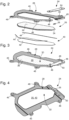
- the light guide is, by way of non-limiting example, of generally parallelepiped shape and comprises a part transparent central part 26 and an opaque peripheral part 28 made of a light-absorbing material and surrounding the central part, the opaque peripheral part 28 being integral with the transparent central part 26.
- the transparent central 26 and opaque peripheral parts 28 are made of a plastic material, they can be made integral with each other, for example by gluing or by heat welding.
- the transparent central part 26 of the light guide 24 comprises an upper surface 30 and a lower surface 32 which extend at a constant distance from each other, the upper surfaces 30 and lower 32 being connected together by a side edge 34.
- the upper surfaces 30 and lower 32 are flat and extend parallel to each other. It goes without saying that according to an embodiment not illustrated in the drawing, the upper surfaces 30 and lower 32 could be curved and be separated by a constant distance from each other to adapt to a display device of the same profile.
- the light guide 24 is intended to illuminate a display device (not shown) from below.
- a plurality of light extractors 36 structured in the upper surface 30 are intended to extract upwards the light injected into the light guide 24 by a light source 38 such as an optically coupled light-emitting diode with the light guide 24.
- a light source 38 such as an optically coupled light-emitting diode with the light guide 24.
- light extractors 36 can be structured in one and/or the other of the upper 30 and lower 32 surfaces of the light guide 24.
- light extractors 36 are structured in the lower surface 32 of the central part 26 of the light guide 24 in the case where the latter is used to illuminate a display device from above.
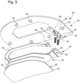
- the surface of the central part 26 of the light guide 24 which is opposite the surface of the central part 26 of the light guide 24 through which the light produced by the light source 38 escapes is provided with a reflective layer 40.
- This reflective layer 40 can be directly structured on the surface of the central part 26 of the light guide 24 opposite the surface through which the light escapes, or else be formed for example by a film 42 fixed on the surface of the central part 26 of the light guide 24 by means of one or two portions 44 adhesive tape on both sides.
- the opaque peripheral part 28 comprises one or more holes 46 for mounting the light guide 24 on a support part (not shown) as well as at least one tenon 48 (two in the example shown) for the fixing a sheet of printed circuit 50 serving as a support for the light source 38.
- the peripheral part 28 of the light guide 24 has an outer edge 52 by which the light guide 24 is fixed on a support part 54, for example a plate or a bridge of a watch movement, which is provided with one or more fixing pins 56 capable of being thermally deformed to hold the light guide 24 against the support part 54 by the outer edge 52 of its peripheral part 28.
- peripheral part 28 of the light guide 24 is pierced with two holes 58 for the passage of two contact springs 60 which bear on two contact pads 62 of the printed circuit sheet 50 to electrically connect the light source 38 to an electrical power source (not shown).
- the peripheral part 28 of the light guide 24 delimits a cavity 64 in which the central part 26 of the light guide 24 is received, with if necessary the interposition of a reflective layer between the central part 26 and the bottom of the cavity 58.
- An adhesive seal 66 placed around the periphery of the central part 26 makes it possible to secure the latter with the peripheral part 28 of the light guide 24
Landscapes
- Physics & Mathematics (AREA)
- General Physics & Mathematics (AREA)
- Optics & Photonics (AREA)
- Chemical & Material Sciences (AREA)
- Crystallography & Structural Chemistry (AREA)
- Nonlinear Science (AREA)
- Mathematical Physics (AREA)
- Planar Illumination Modules (AREA)
- Details Of Measuring Devices (AREA)
- Illuminated Signs And Luminous Advertising (AREA)
Claims (5)
- Lichtleiter zur Beleuchtung einer Anzeigevorrichtung in einem Uhrmachereistück, in welche das von einer Lichtquelle (38) erzeugte Licht eingespeist wird, die optisch mit dem Lichtleiter (24) gekoppelt ist, wobei der Lichtleiter (24) einen ersten Mittelteil (26) umfasst, der aus einem transparenten Werkstoff hergestellt ist, in dem Lichtauswerfer (36) strukturiert sind, dank derer das von der Lichtquelle (38) erzeugte Licht aus dem Lichtleiter ausgeworfen wird, dadurch gekennzeichnet, dass der Lichtleiter einen zweiten Peripherieteil (28) umfasst, der aus einem Werkstoff hergestellt ist, der das Licht in der Masse absorbiert, und den Mittelteil (26) umgibt, wobei der Peripherieteil (28) durch ein Klebeband (44) oder durch eine Klebeverbindung (66) fest mit dem Mittelteil (26) verbunden ist, wobei der Peripherieteil (28) lokal eine Unterbrechung aufweist, in der die Lichtquelle (38) angeordnet ist, wobei der Peripherieteil (28) ein oder mehrere Löcher (46) zur Montage des Lichtleiters (24) an einem Stützstück, sowie mindestens einen Dübel (42) zur Befestigung einer Schaltungsblatts (44) umfasst, das als Stütze für die Lichtquelle (38) dient.
- Lichtleiter zur Beleuchtung einer Anzeigevorrichtung in einem Uhrmachereistück, in welche das von einer Lichtquelle (38) erzeugte Licht eingespeist wird, die optisch mit dem Lichtleiter (24) gekoppelt ist, wobei der Lichtleiter (24) einen ersten Mittelteil (26) umfasst, der aus einem transparenten Werkstoff hergestellt ist, in dem Lichtauswerfer (36) strukturiert sind, dank derer das von der Lichtquelle (38) erzeugte Licht aus dem Lichtleiter ausgeworfen wird, dadurch gekennzeichnet, dass der Lichtleiter einen zweiten Peripherieteil (28) umfasst, der aus einem Werkstoff hergestellt ist, der das Licht in der Masse absorbiert, und den Mittelteil (26) umgibt, wobei der Peripherieteil (28) durch ein Klebeband (44) oder durch eine Klebeverbindung (66) fest mit dem Mittelteil (26) verbunden ist, wobei der Peripherieteil (28) lokal eine Unterbrechung aufweist, in der die Lichtquelle (38) angeordnet ist, wobei der Peripherieteil (28) des Lichtleiters (24) einen äußeren Rand aufweist, über den der Lichtleiter (24) an einem Stützstück befestigt ist, das mit mindestens einem thermisch verformten Befestigungsdübel versehen ist, um den Lichtleiter (24) über den äußeren Rand seines Peripherieteils (28) am Stützstück zu halten.
- Lichtleiter nach einem der Ansprüche 1 und 2, dadurch gekennzeichnet, dass der Mittelteil (26) des Lichtleiters (24) eine obere Oberfläche (30) und eine untere Oberfläche (32) umfasst, die sich in einem konstanten Abstand voneinander erstrecken, wobei die obere (30) und untere (32) Oberfläche durch einen seitlichen Rand (34) miteinander verbunden sind, wobei Lichtauswerfer (36) in mindestens einer von der oberen (30) oder unteren (32) Oberfläche strukturiert sind.
- Lichtleiter nach einem der Ansprüche 1 bis 3, dadurch gekennzeichnet, dass der Peripherieteil (28) des Lichtleiters (24) einen Hohlraum (64) begrenzt, in dem der Mittelteil (26) des Lichtleiters (24) aufgenommen ist.
- Lichtleiter nach einem der Ansprüche 1 bis 4, dadurch gekennzeichnet, dass die Oberfläche des Mittelteils (26) des Lichtleiters (24), die der Oberfläche des Mittelteils (26) des Lichtleiters (24) gegenüberliegt, durch die das von der Lichtquelle (38) erzeugte Licht austritt, mit einer reflektierenden Schicht (40) versehen ist.
Priority Applications (5)
| Application Number | Priority Date | Filing Date | Title |
|---|---|---|---|
| EP15199765.7A EP3181998B1 (de) | 2015-12-14 | 2015-12-14 | Lichtwellenleiter zur beleuchtung einer anzeigevorrichtung |
| FIEP15199765.7T FI3181998T3 (fi) | 2015-12-14 | 2015-12-14 | Valojohdin näyttölaitteen valaisemiseksi |
| JP2016181381A JP6499627B2 (ja) | 2015-12-14 | 2016-09-16 | ディスプレイ装置を照明するための光導体 |
| US15/275,780 US10495809B2 (en) | 2015-12-14 | 2016-09-26 | Light guide for lighting a display device |
| CN201610898832.9A CN106932852B (zh) | 2015-12-14 | 2016-10-14 | 用于为显示装置照明的光导设备 |
Applications Claiming Priority (1)
| Application Number | Priority Date | Filing Date | Title |
|---|---|---|---|
| EP15199765.7A EP3181998B1 (de) | 2015-12-14 | 2015-12-14 | Lichtwellenleiter zur beleuchtung einer anzeigevorrichtung |
Publications (2)
| Publication Number | Publication Date |
|---|---|
| EP3181998A1 EP3181998A1 (de) | 2017-06-21 |
| EP3181998B1 true EP3181998B1 (de) | 2024-08-07 |
Family
ID=54849816
Family Applications (1)
| Application Number | Title | Priority Date | Filing Date |
|---|---|---|---|
| EP15199765.7A Active EP3181998B1 (de) | 2015-12-14 | 2015-12-14 | Lichtwellenleiter zur beleuchtung einer anzeigevorrichtung |
Country Status (5)
| Country | Link |
|---|---|
| US (1) | US10495809B2 (de) |
| EP (1) | EP3181998B1 (de) |
| JP (1) | JP6499627B2 (de) |
| CN (1) | CN106932852B (de) |
| FI (1) | FI3181998T3 (de) |
Citations (4)
| Publication number | Priority date | Publication date | Assignee | Title |
|---|---|---|---|---|
| CN102062972A (zh) * | 2010-11-12 | 2011-05-18 | 友达光电股份有限公司 | 平面显示结构及其制造方法 |
| US20110255023A1 (en) * | 2010-04-15 | 2011-10-20 | Doyle David A | Electronic device display structures with controlled chassis reflections |
| US20130063978A1 (en) * | 2011-09-09 | 2013-03-14 | Shawn R. Gettemy | Chassis for Display Backlight |
| DE202015005982U1 (de) * | 2015-08-24 | 2015-10-01 | Eta Sa Manufacture Horlogère Suisse | Zeitmessgerät mit einem Hintergrundbeleuchtungsmodul für eine digitale Datenanzeigevorrichtung |
Family Cites Families (15)
| Publication number | Priority date | Publication date | Assignee | Title |
|---|---|---|---|---|
| JP3543910B2 (ja) * | 1996-10-11 | 2004-07-21 | 株式会社エンプラス | サイドライト型面光源装置及び表示装置 |
| JP2001156337A (ja) * | 1999-11-25 | 2001-06-08 | Kyushu Hitachi Maxell Ltd | 小形電気機器用の導光体 |
| JP2004095390A (ja) * | 2002-08-30 | 2004-03-25 | Fujitsu Display Technologies Corp | 照明装置及び表示装置 |
| EP1566686A1 (de) * | 2004-02-20 | 2005-08-24 | ETA SA Manufacture Horlogère Suisse | Hintergrundbeleuchtungsvorrichtung für Anzeigeelement |
| US8113695B2 (en) * | 2005-02-04 | 2012-02-14 | Adac Plastics, Inc. | Trim component with concealed indicium |
| CN1869738A (zh) * | 2005-05-24 | 2006-11-29 | 鸿富锦精密工业(深圳)有限公司 | 导光元件和其制备方法,以及其背光模组 |
| US20120307523A1 (en) * | 2010-02-25 | 2012-12-06 | Sharp Kabushiki Kaisha | Light source device and display device |
| DE102011013206A1 (de) * | 2011-03-05 | 2012-09-06 | Diehl Aerospace Gmbh | Flächenleuchte, insbesondere für Flugzugkabinen |
| EP2714469A1 (de) * | 2011-05-24 | 2014-04-09 | Johnson Controls Interiors GmbH & Co. KG | Beleuchtungsvorrichtung für einen fahrzeuginnenraum |
| CN102829406A (zh) * | 2011-06-14 | 2012-12-19 | 海洋王照明科技股份有限公司 | 灯具及其导光板 |
| EP2546684A1 (de) * | 2011-07-15 | 2013-01-16 | ETA SA Manufacture Horlogère Suisse | Lichtwellenleiter zur Beleuchtung einer Informationsanzeigevorrichtung |
| US8789995B2 (en) * | 2012-01-06 | 2014-07-29 | Qualcomm Mems Technologies, Inc. | Light guide with at least partially non-transmissive coating on ledge region |
| JP5396498B2 (ja) * | 2012-03-02 | 2014-01-22 | 株式会社エス・ケー・ジー | 発光装置 |
| JP2015044474A (ja) * | 2013-08-28 | 2015-03-12 | 東芝ライテック株式会社 | 照明装置 |
| CN104111492B (zh) * | 2014-05-16 | 2016-09-28 | 京东方光科技有限公司 | 导光板成型模具及制作方法 |
-
2015
- 2015-12-14 EP EP15199765.7A patent/EP3181998B1/de active Active
- 2015-12-14 FI FIEP15199765.7T patent/FI3181998T3/fi active
-
2016
- 2016-09-16 JP JP2016181381A patent/JP6499627B2/ja active Active
- 2016-09-26 US US15/275,780 patent/US10495809B2/en active Active
- 2016-10-14 CN CN201610898832.9A patent/CN106932852B/zh active Active
Patent Citations (4)
| Publication number | Priority date | Publication date | Assignee | Title |
|---|---|---|---|---|
| US20110255023A1 (en) * | 2010-04-15 | 2011-10-20 | Doyle David A | Electronic device display structures with controlled chassis reflections |
| CN102062972A (zh) * | 2010-11-12 | 2011-05-18 | 友达光电股份有限公司 | 平面显示结构及其制造方法 |
| US20130063978A1 (en) * | 2011-09-09 | 2013-03-14 | Shawn R. Gettemy | Chassis for Display Backlight |
| DE202015005982U1 (de) * | 2015-08-24 | 2015-10-01 | Eta Sa Manufacture Horlogère Suisse | Zeitmessgerät mit einem Hintergrundbeleuchtungsmodul für eine digitale Datenanzeigevorrichtung |
Also Published As
| Publication number | Publication date |
|---|---|
| CN106932852A (zh) | 2017-07-07 |
| US10495809B2 (en) | 2019-12-03 |
| JP2017112094A (ja) | 2017-06-22 |
| JP6499627B2 (ja) | 2019-04-10 |
| EP3181998A1 (de) | 2017-06-21 |
| US20170168229A1 (en) | 2017-06-15 |
| FI3181998T3 (fi) | 2024-10-31 |
| CN106932852B (zh) | 2019-12-27 |
Similar Documents
| Publication | Publication Date | Title |
|---|---|---|
| EP1566686A1 (de) | Hintergrundbeleuchtungsvorrichtung für Anzeigeelement | |
| EP2743785B1 (de) | Flexible tragbare elektronische Vorrichtung | |
| CH705042B1 (fr) | Montre comprenant une cellule d'alimentation en énergie. | |
| FR2782829A1 (fr) | Panneaux d'affichage lumineux | |
| CH705046A2 (fr) | Montre. | |
| EP3650958A1 (de) | Gegenstand, der mit einer elektrooptischen anzeigevorrichtung ausgestattet ist | |
| EP1862873A1 (de) | Anzeigeeinrichtung für ein tragbares Gerät, wie eine Uhr | |
| EP4421568B1 (de) | Uhr mit einer transparenten oder transluzenten dekorativen struktur, insbesondere einer halbemail | |
| EP3181998B1 (de) | Lichtwellenleiter zur beleuchtung einer anzeigevorrichtung | |
| EP1862874B1 (de) | Anzeigevorrichtung für ein tragbares Gerät, wie beispielsweise eine Uhr | |
| EP3719586B1 (de) | Uhr mit besonderen ästhetischen effekten | |
| CH713623A1 (fr) | Dispositif de lecture d'un appareil à glace ou écran. | |
| EP2584413B1 (de) | Vorrichtung zum Befestigen eines Glases auf einem Mittelteil eines Armbanduhrgehäuses | |
| CH711862A2 (fr) | Guide de lumière pour l'éclairage d'un dispositif d'affichage. | |
| EP2684182B1 (de) | Durchscheinende bedruckte folie zur anzeige einer aufschrift mittels hintergrundbeleuchtung | |
| EP2673676B1 (de) | Uhr mit einer einfassung und verfahren zur anbringung einer solchen einfassung | |
| EP1566687B1 (de) | Hintergrundbeleuchtungsvorrichtung für Anzeigeelement | |
| CH701301B1 (fr) | Pièce d'horlogerie comprenant au moins une source de lumière. | |
| EP0886171A1 (de) | Flüssigkristallanzeigevorrichtung und diese enthaltendes elektronisches Gerät | |
| EP1319998B1 (de) | Leuchtzeiger und diese aufweisendes Anzeigegerät, insbesondere für eine Uhr | |
| WO2013010689A1 (fr) | Guide de lumière pour l'éclairage d'un dispositif d'affichage d'informations | |
| CH697569B1 (fr) | Dispositif de rétro-éclairage d'un élément d'affichage d'information d'un objet portable. | |
| CH715285B1 (fr) | Objet muni d'un dispositif d'affichage électrooptique. | |
| CH704453A2 (fr) | Montre comprenant une lunette et procédé de fixation d'une telle lunette. | |
| CH619050A5 (en) | Passive electrooptic display device |
Legal Events
| Date | Code | Title | Description |
|---|---|---|---|
| PUAI | Public reference made under article 153(3) epc to a published international application that has entered the european phase |
Free format text: ORIGINAL CODE: 0009012 |
|
| STAA | Information on the status of an ep patent application or granted ep patent |
Free format text: STATUS: THE APPLICATION HAS BEEN PUBLISHED |
|
| AK | Designated contracting states |
Kind code of ref document: A1 Designated state(s): AL AT BE BG CH CY CZ DE DK EE ES FI FR GB GR HR HU IE IS IT LI LT LU LV MC MK MT NL NO PL PT RO RS SE SI SK SM TR |
|
| AX | Request for extension of the european patent |
Extension state: BA ME |
|
| STAA | Information on the status of an ep patent application or granted ep patent |
Free format text: STATUS: REQUEST FOR EXAMINATION WAS MADE |
|
| 17P | Request for examination filed |
Effective date: 20171221 |
|
| RBV | Designated contracting states (corrected) |
Designated state(s): AL AT BE BG CH CY CZ DE DK EE ES FI FR GB GR HR HU IE IS IT LI LT LU LV MC MK MT NL NO PL PT RO RS SE SI SK SM TR |
|
| STAA | Information on the status of an ep patent application or granted ep patent |
Free format text: STATUS: EXAMINATION IS IN PROGRESS |
|
| 17Q | First examination report despatched |
Effective date: 20180223 |
|
| P01 | Opt-out of the competence of the unified patent court (upc) registered |
Effective date: 20230701 |
|
| GRAP | Despatch of communication of intention to grant a patent |
Free format text: ORIGINAL CODE: EPIDOSNIGR1 |
|
| STAA | Information on the status of an ep patent application or granted ep patent |
Free format text: STATUS: GRANT OF PATENT IS INTENDED |
|
| INTG | Intention to grant announced |
Effective date: 20240408 |
|
| GRAS | Grant fee paid |
Free format text: ORIGINAL CODE: EPIDOSNIGR3 |
|
| GRAA | (expected) grant |
Free format text: ORIGINAL CODE: 0009210 |
|
| STAA | Information on the status of an ep patent application or granted ep patent |
Free format text: STATUS: THE PATENT HAS BEEN GRANTED |
|
| AK | Designated contracting states |
Kind code of ref document: B1 Designated state(s): AL AT BE BG CH CY CZ DE DK EE ES FI FR GB GR HR HU IE IS IT LI LT LU LV MC MK MT NL NO PL PT RO RS SE SI SK SM TR |
|
| REG | Reference to a national code |
Ref country code: GB Ref legal event code: FG4D Free format text: NOT ENGLISH |
|
| REG | Reference to a national code |
Ref country code: CH Ref legal event code: EP |
|
| REG | Reference to a national code |
Ref country code: IE Ref legal event code: FG4D Free format text: LANGUAGE OF EP DOCUMENT: FRENCH |
|
| REG | Reference to a national code |
Ref country code: DE Ref legal event code: R096 Ref document number: 602015089434 Country of ref document: DE |
|
| REG | Reference to a national code |
Ref country code: FI Ref legal event code: FGE |
|
| REG | Reference to a national code |
Ref country code: LT Ref legal event code: MG9D |
|
| REG | Reference to a national code |
Ref country code: NL Ref legal event code: MP Effective date: 20240807 |
|
| PG25 | Lapsed in a contracting state [announced via postgrant information from national office to epo] |
Ref country code: NO Free format text: LAPSE BECAUSE OF FAILURE TO SUBMIT A TRANSLATION OF THE DESCRIPTION OR TO PAY THE FEE WITHIN THE PRESCRIBED TIME-LIMIT Effective date: 20241107 |
|
| REG | Reference to a national code |
Ref country code: AT Ref legal event code: MK05 Ref document number: 1711307 Country of ref document: AT Kind code of ref document: T Effective date: 20240807 |
|
| PG25 | Lapsed in a contracting state [announced via postgrant information from national office to epo] |
Ref country code: PL Free format text: LAPSE BECAUSE OF FAILURE TO SUBMIT A TRANSLATION OF THE DESCRIPTION OR TO PAY THE FEE WITHIN THE PRESCRIBED TIME-LIMIT Effective date: 20240807 Ref country code: NL Free format text: LAPSE BECAUSE OF FAILURE TO SUBMIT A TRANSLATION OF THE DESCRIPTION OR TO PAY THE FEE WITHIN THE PRESCRIBED TIME-LIMIT Effective date: 20240807 Ref country code: PT Free format text: LAPSE BECAUSE OF FAILURE TO SUBMIT A TRANSLATION OF THE DESCRIPTION OR TO PAY THE FEE WITHIN THE PRESCRIBED TIME-LIMIT Effective date: 20241209 Ref country code: GR Free format text: LAPSE BECAUSE OF FAILURE TO SUBMIT A TRANSLATION OF THE DESCRIPTION OR TO PAY THE FEE WITHIN THE PRESCRIBED TIME-LIMIT Effective date: 20241108 |
|
| PG25 | Lapsed in a contracting state [announced via postgrant information from national office to epo] |
Ref country code: BG Free format text: LAPSE BECAUSE OF FAILURE TO SUBMIT A TRANSLATION OF THE DESCRIPTION OR TO PAY THE FEE WITHIN THE PRESCRIBED TIME-LIMIT Effective date: 20240807 |
|
| PG25 | Lapsed in a contracting state [announced via postgrant information from national office to epo] |
Ref country code: LV Free format text: LAPSE BECAUSE OF FAILURE TO SUBMIT A TRANSLATION OF THE DESCRIPTION OR TO PAY THE FEE WITHIN THE PRESCRIBED TIME-LIMIT Effective date: 20240807 |
|
| PG25 | Lapsed in a contracting state [announced via postgrant information from national office to epo] |
Ref country code: IS Free format text: LAPSE BECAUSE OF FAILURE TO SUBMIT A TRANSLATION OF THE DESCRIPTION OR TO PAY THE FEE WITHIN THE PRESCRIBED TIME-LIMIT Effective date: 20241207 Ref country code: AT Free format text: LAPSE BECAUSE OF FAILURE TO SUBMIT A TRANSLATION OF THE DESCRIPTION OR TO PAY THE FEE WITHIN THE PRESCRIBED TIME-LIMIT Effective date: 20240807 |
|
| PG25 | Lapsed in a contracting state [announced via postgrant information from national office to epo] |
Ref country code: HR Free format text: LAPSE BECAUSE OF FAILURE TO SUBMIT A TRANSLATION OF THE DESCRIPTION OR TO PAY THE FEE WITHIN THE PRESCRIBED TIME-LIMIT Effective date: 20240807 |
|
| PG25 | Lapsed in a contracting state [announced via postgrant information from national office to epo] |
Ref country code: RS Free format text: LAPSE BECAUSE OF FAILURE TO SUBMIT A TRANSLATION OF THE DESCRIPTION OR TO PAY THE FEE WITHIN THE PRESCRIBED TIME-LIMIT Effective date: 20241107 Ref country code: ES Free format text: LAPSE BECAUSE OF FAILURE TO SUBMIT A TRANSLATION OF THE DESCRIPTION OR TO PAY THE FEE WITHIN THE PRESCRIBED TIME-LIMIT Effective date: 20240807 |
|
| PG25 | Lapsed in a contracting state [announced via postgrant information from national office to epo] |
Ref country code: RS Free format text: LAPSE BECAUSE OF FAILURE TO SUBMIT A TRANSLATION OF THE DESCRIPTION OR TO PAY THE FEE WITHIN THE PRESCRIBED TIME-LIMIT Effective date: 20241107 Ref country code: PT Free format text: LAPSE BECAUSE OF FAILURE TO SUBMIT A TRANSLATION OF THE DESCRIPTION OR TO PAY THE FEE WITHIN THE PRESCRIBED TIME-LIMIT Effective date: 20241209 Ref country code: PL Free format text: LAPSE BECAUSE OF FAILURE TO SUBMIT A TRANSLATION OF THE DESCRIPTION OR TO PAY THE FEE WITHIN THE PRESCRIBED TIME-LIMIT Effective date: 20240807 Ref country code: NO Free format text: LAPSE BECAUSE OF FAILURE TO SUBMIT A TRANSLATION OF THE DESCRIPTION OR TO PAY THE FEE WITHIN THE PRESCRIBED TIME-LIMIT Effective date: 20241107 Ref country code: NL Free format text: LAPSE BECAUSE OF FAILURE TO SUBMIT A TRANSLATION OF THE DESCRIPTION OR TO PAY THE FEE WITHIN THE PRESCRIBED TIME-LIMIT Effective date: 20240807 Ref country code: LV Free format text: LAPSE BECAUSE OF FAILURE TO SUBMIT A TRANSLATION OF THE DESCRIPTION OR TO PAY THE FEE WITHIN THE PRESCRIBED TIME-LIMIT Effective date: 20240807 Ref country code: IS Free format text: LAPSE BECAUSE OF FAILURE TO SUBMIT A TRANSLATION OF THE DESCRIPTION OR TO PAY THE FEE WITHIN THE PRESCRIBED TIME-LIMIT Effective date: 20241207 Ref country code: HR Free format text: LAPSE BECAUSE OF FAILURE TO SUBMIT A TRANSLATION OF THE DESCRIPTION OR TO PAY THE FEE WITHIN THE PRESCRIBED TIME-LIMIT Effective date: 20240807 Ref country code: GR Free format text: LAPSE BECAUSE OF FAILURE TO SUBMIT A TRANSLATION OF THE DESCRIPTION OR TO PAY THE FEE WITHIN THE PRESCRIBED TIME-LIMIT Effective date: 20241108 Ref country code: ES Free format text: LAPSE BECAUSE OF FAILURE TO SUBMIT A TRANSLATION OF THE DESCRIPTION OR TO PAY THE FEE WITHIN THE PRESCRIBED TIME-LIMIT Effective date: 20240807 Ref country code: BG Free format text: LAPSE BECAUSE OF FAILURE TO SUBMIT A TRANSLATION OF THE DESCRIPTION OR TO PAY THE FEE WITHIN THE PRESCRIBED TIME-LIMIT Effective date: 20240807 Ref country code: AT Free format text: LAPSE BECAUSE OF FAILURE TO SUBMIT A TRANSLATION OF THE DESCRIPTION OR TO PAY THE FEE WITHIN THE PRESCRIBED TIME-LIMIT Effective date: 20240807 |
|
| PG25 | Lapsed in a contracting state [announced via postgrant information from national office to epo] |
Ref country code: SM Free format text: LAPSE BECAUSE OF FAILURE TO SUBMIT A TRANSLATION OF THE DESCRIPTION OR TO PAY THE FEE WITHIN THE PRESCRIBED TIME-LIMIT Effective date: 20240807 Ref country code: DK Free format text: LAPSE BECAUSE OF FAILURE TO SUBMIT A TRANSLATION OF THE DESCRIPTION OR TO PAY THE FEE WITHIN THE PRESCRIBED TIME-LIMIT Effective date: 20240807 Ref country code: RO Free format text: LAPSE BECAUSE OF FAILURE TO SUBMIT A TRANSLATION OF THE DESCRIPTION OR TO PAY THE FEE WITHIN THE PRESCRIBED TIME-LIMIT Effective date: 20240807 |
|
| PG25 | Lapsed in a contracting state [announced via postgrant information from national office to epo] |
Ref country code: EE Free format text: LAPSE BECAUSE OF FAILURE TO SUBMIT A TRANSLATION OF THE DESCRIPTION OR TO PAY THE FEE WITHIN THE PRESCRIBED TIME-LIMIT Effective date: 20240807 |
|
| PGFP | Annual fee paid to national office [announced via postgrant information from national office to epo] |
Ref country code: CH Payment date: 20250101 Year of fee payment: 10 |
|
| PG25 | Lapsed in a contracting state [announced via postgrant information from national office to epo] |
Ref country code: CZ Free format text: LAPSE BECAUSE OF FAILURE TO SUBMIT A TRANSLATION OF THE DESCRIPTION OR TO PAY THE FEE WITHIN THE PRESCRIBED TIME-LIMIT Effective date: 20240807 |
|
| PG25 | Lapsed in a contracting state [announced via postgrant information from national office to epo] |
Ref country code: SK Free format text: LAPSE BECAUSE OF FAILURE TO SUBMIT A TRANSLATION OF THE DESCRIPTION OR TO PAY THE FEE WITHIN THE PRESCRIBED TIME-LIMIT Effective date: 20240807 |
|
| REG | Reference to a national code |
Ref country code: DE Ref legal event code: R097 Ref document number: 602015089434 Country of ref document: DE |
|
| PLBE | No opposition filed within time limit |
Free format text: ORIGINAL CODE: 0009261 |
|
| STAA | Information on the status of an ep patent application or granted ep patent |
Free format text: STATUS: NO OPPOSITION FILED WITHIN TIME LIMIT |
|
| PG25 | Lapsed in a contracting state [announced via postgrant information from national office to epo] |
Ref country code: MC Free format text: LAPSE BECAUSE OF FAILURE TO SUBMIT A TRANSLATION OF THE DESCRIPTION OR TO PAY THE FEE WITHIN THE PRESCRIBED TIME-LIMIT Effective date: 20240807 |
|
| 26N | No opposition filed |
Effective date: 20250508 |
|
| PG25 | Lapsed in a contracting state [announced via postgrant information from national office to epo] |
Ref country code: LU Free format text: LAPSE BECAUSE OF NON-PAYMENT OF DUE FEES Effective date: 20241214 |
|
| PG25 | Lapsed in a contracting state [announced via postgrant information from national office to epo] |
Ref country code: SE Free format text: LAPSE BECAUSE OF FAILURE TO SUBMIT A TRANSLATION OF THE DESCRIPTION OR TO PAY THE FEE WITHIN THE PRESCRIBED TIME-LIMIT Effective date: 20240807 |
|
| REG | Reference to a national code |
Ref country code: BE Ref legal event code: MM Effective date: 20241231 |
|
| PG25 | Lapsed in a contracting state [announced via postgrant information from national office to epo] |
Ref country code: BE Free format text: LAPSE BECAUSE OF NON-PAYMENT OF DUE FEES Effective date: 20241231 |
|
| PG25 | Lapsed in a contracting state [announced via postgrant information from national office to epo] |
Ref country code: IE Free format text: LAPSE BECAUSE OF NON-PAYMENT OF DUE FEES Effective date: 20241214 |
|
| REG | Reference to a national code |
Ref country code: CH Ref legal event code: U11 Free format text: ST27 STATUS EVENT CODE: U-0-0-U10-U11 (AS PROVIDED BY THE NATIONAL OFFICE) Effective date: 20260101 |
|
| PGFP | Annual fee paid to national office [announced via postgrant information from national office to epo] |
Ref country code: DE Payment date: 20251126 Year of fee payment: 11 |
|
| PGFP | Annual fee paid to national office [announced via postgrant information from national office to epo] |
Ref country code: GB Payment date: 20251119 Year of fee payment: 11 |
|
| PGFP | Annual fee paid to national office [announced via postgrant information from national office to epo] |
Ref country code: FI Payment date: 20251119 Year of fee payment: 11 |
|
| PGFP | Annual fee paid to national office [announced via postgrant information from national office to epo] |
Ref country code: FR Payment date: 20251120 Year of fee payment: 11 |
|
| PG25 | Lapsed in a contracting state [announced via postgrant information from national office to epo] |
Ref country code: IT Free format text: LAPSE BECAUSE OF FAILURE TO SUBMIT A TRANSLATION OF THE DESCRIPTION OR TO PAY THE FEE WITHIN THE PRESCRIBED TIME-LIMIT Effective date: 20240807 |