EP3181850B1 - Exhaust gas treatment device, method for processing exhaust gas, and motor vehicle - Google Patents
Exhaust gas treatment device, method for processing exhaust gas, and motor vehicle Download PDFInfo
- Publication number
- EP3181850B1 EP3181850B1 EP17155494.2A EP17155494A EP3181850B1 EP 3181850 B1 EP3181850 B1 EP 3181850B1 EP 17155494 A EP17155494 A EP 17155494A EP 3181850 B1 EP3181850 B1 EP 3181850B1
- Authority
- EP
- European Patent Office
- Prior art keywords
- exhaust gas
- reduction catalyst
- catalyst
- reduction
- combustion unit
- Prior art date
- Legal status (The legal status is an assumption and is not a legal conclusion. Google has not performed a legal analysis and makes no representation as to the accuracy of the status listed.)
- Active
Links
- 238000000034 method Methods 0.000 title claims description 7
- 239000003054 catalyst Substances 0.000 claims description 131
- 230000009467 reduction Effects 0.000 claims description 114
- 238000006722 reduction reaction Methods 0.000 claims description 114
- 238000002485 combustion reaction Methods 0.000 claims description 75
- 230000003647 oxidation Effects 0.000 claims description 47
- 238000007254 oxidation reaction Methods 0.000 claims description 47
- 238000001816 cooling Methods 0.000 claims description 37
- 239000003638 chemical reducing agent Substances 0.000 claims description 28
- 239000002245 particle Substances 0.000 claims description 25
- 238000011144 upstream manufacturing Methods 0.000 claims description 15
- 238000010531 catalytic reduction reaction Methods 0.000 claims description 8
- 238000002347 injection Methods 0.000 claims description 8
- 239000007924 injection Substances 0.000 claims description 8
- 239000002826 coolant Substances 0.000 claims description 5
- 239000007789 gas Substances 0.000 description 117
- 230000003197 catalytic effect Effects 0.000 description 27
- QGZKDVFQNNGYKY-UHFFFAOYSA-N Ammonia Chemical compound N QGZKDVFQNNGYKY-UHFFFAOYSA-N 0.000 description 14
- IJGRMHOSHXDMSA-UHFFFAOYSA-N Atomic nitrogen Chemical compound N#N IJGRMHOSHXDMSA-UHFFFAOYSA-N 0.000 description 10
- MWUXSHHQAYIFBG-UHFFFAOYSA-N Nitric oxide Chemical class O=[N] MWUXSHHQAYIFBG-UHFFFAOYSA-N 0.000 description 10
- 229910021529 ammonia Inorganic materials 0.000 description 7
- 238000006243 chemical reaction Methods 0.000 description 7
- 230000008901 benefit Effects 0.000 description 6
- 239000000446 fuel Substances 0.000 description 5
- 229910052757 nitrogen Inorganic materials 0.000 description 5
- XLYOFNOQVPJJNP-UHFFFAOYSA-N water Substances O XLYOFNOQVPJJNP-UHFFFAOYSA-N 0.000 description 5
- 239000000126 substance Substances 0.000 description 4
- XSQUKJJJFZCRTK-UHFFFAOYSA-N Urea Chemical compound NC(N)=O XSQUKJJJFZCRTK-UHFFFAOYSA-N 0.000 description 3
- 239000004202 carbamide Substances 0.000 description 3
- 230000003111 delayed effect Effects 0.000 description 3
- 229910017464 nitrogen compound Inorganic materials 0.000 description 3
- 150000002830 nitrogen compounds Chemical class 0.000 description 3
- 239000002243 precursor Substances 0.000 description 3
- 239000003570 air Substances 0.000 description 2
- 238000004140 cleaning Methods 0.000 description 2
- 238000000354 decomposition reaction Methods 0.000 description 2
- 230000002349 favourable effect Effects 0.000 description 2
- 238000010438 heat treatment Methods 0.000 description 2
- 238000004519 manufacturing process Methods 0.000 description 2
- 239000000243 solution Substances 0.000 description 2
- 206010063493 Premature ageing Diseases 0.000 description 1
- 208000032038 Premature aging Diseases 0.000 description 1
- 239000012080 ambient air Substances 0.000 description 1
- 239000007864 aqueous solution Substances 0.000 description 1
- 238000006555 catalytic reaction Methods 0.000 description 1
- 239000003795 chemical substances by application Substances 0.000 description 1
- 230000008878 coupling Effects 0.000 description 1
- 238000010168 coupling process Methods 0.000 description 1
- 238000005859 coupling reaction Methods 0.000 description 1
- 230000018109 developmental process Effects 0.000 description 1
- 238000001704 evaporation Methods 0.000 description 1
- 230000008020 evaporation Effects 0.000 description 1
- 238000000265 homogenisation Methods 0.000 description 1
- 230000006872 improvement Effects 0.000 description 1
- 239000000203 mixture Substances 0.000 description 1
- 238000005457 optimization Methods 0.000 description 1
- 230000005855 radiation Effects 0.000 description 1
- 238000011946 reduction process Methods 0.000 description 1
- 239000011343 solid material Substances 0.000 description 1
- 238000009827 uniform distribution Methods 0.000 description 1
- WTHDKMILWLGDKL-UHFFFAOYSA-N urea;hydrate Chemical compound O.NC(N)=O WTHDKMILWLGDKL-UHFFFAOYSA-N 0.000 description 1
Images


Classifications
-
- F—MECHANICAL ENGINEERING; LIGHTING; HEATING; WEAPONS; BLASTING
- F01—MACHINES OR ENGINES IN GENERAL; ENGINE PLANTS IN GENERAL; STEAM ENGINES
- F01N—GAS-FLOW SILENCERS OR EXHAUST APPARATUS FOR MACHINES OR ENGINES IN GENERAL; GAS-FLOW SILENCERS OR EXHAUST APPARATUS FOR INTERNAL COMBUSTION ENGINES
- F01N3/00—Exhaust or silencing apparatus having means for purifying, rendering innocuous, or otherwise treating exhaust
- F01N3/08—Exhaust or silencing apparatus having means for purifying, rendering innocuous, or otherwise treating exhaust for rendering innocuous
- F01N3/10—Exhaust or silencing apparatus having means for purifying, rendering innocuous, or otherwise treating exhaust for rendering innocuous by thermal or catalytic conversion of noxious components of exhaust
-
- F—MECHANICAL ENGINEERING; LIGHTING; HEATING; WEAPONS; BLASTING
- F01—MACHINES OR ENGINES IN GENERAL; ENGINE PLANTS IN GENERAL; STEAM ENGINES
- F01N—GAS-FLOW SILENCERS OR EXHAUST APPARATUS FOR MACHINES OR ENGINES IN GENERAL; GAS-FLOW SILENCERS OR EXHAUST APPARATUS FOR INTERNAL COMBUSTION ENGINES
- F01N13/00—Exhaust or silencing apparatus characterised by constructional features ; Exhaust or silencing apparatus, or parts thereof, having pertinent characteristics not provided for in, or of interest apart from, groups F01N1/00 - F01N5/00, F01N9/00, F01N11/00
- F01N13/009—Exhaust or silencing apparatus characterised by constructional features ; Exhaust or silencing apparatus, or parts thereof, having pertinent characteristics not provided for in, or of interest apart from, groups F01N1/00 - F01N5/00, F01N9/00, F01N11/00 having two or more separate purifying devices arranged in series
- F01N13/0097—Exhaust or silencing apparatus characterised by constructional features ; Exhaust or silencing apparatus, or parts thereof, having pertinent characteristics not provided for in, or of interest apart from, groups F01N1/00 - F01N5/00, F01N9/00, F01N11/00 having two or more separate purifying devices arranged in series the purifying devices are arranged in a single housing
-
- F—MECHANICAL ENGINEERING; LIGHTING; HEATING; WEAPONS; BLASTING
- F01—MACHINES OR ENGINES IN GENERAL; ENGINE PLANTS IN GENERAL; STEAM ENGINES
- F01N—GAS-FLOW SILENCERS OR EXHAUST APPARATUS FOR MACHINES OR ENGINES IN GENERAL; GAS-FLOW SILENCERS OR EXHAUST APPARATUS FOR INTERNAL COMBUSTION ENGINES
- F01N3/00—Exhaust or silencing apparatus having means for purifying, rendering innocuous, or otherwise treating exhaust
- F01N3/02—Exhaust or silencing apparatus having means for purifying, rendering innocuous, or otherwise treating exhaust for cooling, or for removing solid constituents of, exhaust
- F01N3/021—Exhaust or silencing apparatus having means for purifying, rendering innocuous, or otherwise treating exhaust for cooling, or for removing solid constituents of, exhaust by means of filters
- F01N3/033—Exhaust or silencing apparatus having means for purifying, rendering innocuous, or otherwise treating exhaust for cooling, or for removing solid constituents of, exhaust by means of filters in combination with other devices
- F01N3/035—Exhaust or silencing apparatus having means for purifying, rendering innocuous, or otherwise treating exhaust for cooling, or for removing solid constituents of, exhaust by means of filters in combination with other devices with catalytic reactors, e.g. catalysed diesel particulate filters
-
- F—MECHANICAL ENGINEERING; LIGHTING; HEATING; WEAPONS; BLASTING
- F01—MACHINES OR ENGINES IN GENERAL; ENGINE PLANTS IN GENERAL; STEAM ENGINES
- F01N—GAS-FLOW SILENCERS OR EXHAUST APPARATUS FOR MACHINES OR ENGINES IN GENERAL; GAS-FLOW SILENCERS OR EXHAUST APPARATUS FOR INTERNAL COMBUSTION ENGINES
- F01N3/00—Exhaust or silencing apparatus having means for purifying, rendering innocuous, or otherwise treating exhaust
- F01N3/08—Exhaust or silencing apparatus having means for purifying, rendering innocuous, or otherwise treating exhaust for rendering innocuous
- F01N3/10—Exhaust or silencing apparatus having means for purifying, rendering innocuous, or otherwise treating exhaust for rendering innocuous by thermal or catalytic conversion of noxious components of exhaust
- F01N3/105—General auxiliary catalysts, e.g. upstream or downstream of the main catalyst
- F01N3/106—Auxiliary oxidation catalysts
-
- F—MECHANICAL ENGINEERING; LIGHTING; HEATING; WEAPONS; BLASTING
- F01—MACHINES OR ENGINES IN GENERAL; ENGINE PLANTS IN GENERAL; STEAM ENGINES
- F01N—GAS-FLOW SILENCERS OR EXHAUST APPARATUS FOR MACHINES OR ENGINES IN GENERAL; GAS-FLOW SILENCERS OR EXHAUST APPARATUS FOR INTERNAL COMBUSTION ENGINES
- F01N3/00—Exhaust or silencing apparatus having means for purifying, rendering innocuous, or otherwise treating exhaust
- F01N3/08—Exhaust or silencing apparatus having means for purifying, rendering innocuous, or otherwise treating exhaust for rendering innocuous
- F01N3/10—Exhaust or silencing apparatus having means for purifying, rendering innocuous, or otherwise treating exhaust for rendering innocuous by thermal or catalytic conversion of noxious components of exhaust
- F01N3/18—Exhaust or silencing apparatus having means for purifying, rendering innocuous, or otherwise treating exhaust for rendering innocuous by thermal or catalytic conversion of noxious components of exhaust characterised by methods of operation; Control
- F01N3/20—Exhaust or silencing apparatus having means for purifying, rendering innocuous, or otherwise treating exhaust for rendering innocuous by thermal or catalytic conversion of noxious components of exhaust characterised by methods of operation; Control specially adapted for catalytic conversion ; Methods of operation or control of catalytic converters
- F01N3/2066—Selective catalytic reduction [SCR]
-
- F—MECHANICAL ENGINEERING; LIGHTING; HEATING; WEAPONS; BLASTING
- F02—COMBUSTION ENGINES; HOT-GAS OR COMBUSTION-PRODUCT ENGINE PLANTS
- F02M—SUPPLYING COMBUSTION ENGINES IN GENERAL WITH COMBUSTIBLE MIXTURES OR CONSTITUENTS THEREOF
- F02M26/00—Engine-pertinent apparatus for adding exhaust gases to combustion-air, main fuel or fuel-air mixture, e.g. by exhaust gas recirculation [EGR] systems
- F02M26/13—Arrangement or layout of EGR passages, e.g. in relation to specific engine parts or for incorporation of accessories
- F02M26/14—Arrangement or layout of EGR passages, e.g. in relation to specific engine parts or for incorporation of accessories in relation to the exhaust system
- F02M26/15—Arrangement or layout of EGR passages, e.g. in relation to specific engine parts or for incorporation of accessories in relation to the exhaust system in relation to engine exhaust purifying apparatus
-
- F—MECHANICAL ENGINEERING; LIGHTING; HEATING; WEAPONS; BLASTING
- F02—COMBUSTION ENGINES; HOT-GAS OR COMBUSTION-PRODUCT ENGINE PLANTS
- F02M—SUPPLYING COMBUSTION ENGINES IN GENERAL WITH COMBUSTIBLE MIXTURES OR CONSTITUENTS THEREOF
- F02M26/00—Engine-pertinent apparatus for adding exhaust gases to combustion-air, main fuel or fuel-air mixture, e.g. by exhaust gas recirculation [EGR] systems
- F02M26/13—Arrangement or layout of EGR passages, e.g. in relation to specific engine parts or for incorporation of accessories
- F02M26/22—Arrangement or layout of EGR passages, e.g. in relation to specific engine parts or for incorporation of accessories with coolers in the recirculation passage
- F02M26/29—Constructional details of the coolers, e.g. pipes, plates, ribs, insulation or materials
- F02M26/30—Connections of coolers to other devices, e.g. to valves, heaters, compressors or filters; Coolers characterised by their location on the engine
-
- F—MECHANICAL ENGINEERING; LIGHTING; HEATING; WEAPONS; BLASTING
- F01—MACHINES OR ENGINES IN GENERAL; ENGINE PLANTS IN GENERAL; STEAM ENGINES
- F01N—GAS-FLOW SILENCERS OR EXHAUST APPARATUS FOR MACHINES OR ENGINES IN GENERAL; GAS-FLOW SILENCERS OR EXHAUST APPARATUS FOR INTERNAL COMBUSTION ENGINES
- F01N2340/00—Dimensional characteristics of the exhaust system, e.g. length, diameter or volume of the apparatus; Spatial arrangements of exhaust apparatuses
- F01N2340/02—Dimensional characteristics of the exhaust system, e.g. length, diameter or volume of the apparatus; Spatial arrangements of exhaust apparatuses characterised by the distance of the apparatus to the engine, or the distance between two exhaust treating apparatuses
-
- F—MECHANICAL ENGINEERING; LIGHTING; HEATING; WEAPONS; BLASTING
- F01—MACHINES OR ENGINES IN GENERAL; ENGINE PLANTS IN GENERAL; STEAM ENGINES
- F01N—GAS-FLOW SILENCERS OR EXHAUST APPARATUS FOR MACHINES OR ENGINES IN GENERAL; GAS-FLOW SILENCERS OR EXHAUST APPARATUS FOR INTERNAL COMBUSTION ENGINES
- F01N2610/00—Adding substances to exhaust gases
- F01N2610/02—Adding substances to exhaust gases the substance being ammonia or urea
-
- F—MECHANICAL ENGINEERING; LIGHTING; HEATING; WEAPONS; BLASTING
- F01—MACHINES OR ENGINES IN GENERAL; ENGINE PLANTS IN GENERAL; STEAM ENGINES
- F01N—GAS-FLOW SILENCERS OR EXHAUST APPARATUS FOR MACHINES OR ENGINES IN GENERAL; GAS-FLOW SILENCERS OR EXHAUST APPARATUS FOR INTERNAL COMBUSTION ENGINES
- F01N2610/00—Adding substances to exhaust gases
- F01N2610/11—Adding substances to exhaust gases the substance or part of the dosing system being cooled
-
- F—MECHANICAL ENGINEERING; LIGHTING; HEATING; WEAPONS; BLASTING
- F01—MACHINES OR ENGINES IN GENERAL; ENGINE PLANTS IN GENERAL; STEAM ENGINES
- F01N—GAS-FLOW SILENCERS OR EXHAUST APPARATUS FOR MACHINES OR ENGINES IN GENERAL; GAS-FLOW SILENCERS OR EXHAUST APPARATUS FOR INTERNAL COMBUSTION ENGINES
- F01N2610/00—Adding substances to exhaust gases
- F01N2610/14—Arrangements for the supply of substances, e.g. conduits
- F01N2610/1453—Sprayers or atomisers; Arrangement thereof in the exhaust apparatus
-
- F—MECHANICAL ENGINEERING; LIGHTING; HEATING; WEAPONS; BLASTING
- F02—COMBUSTION ENGINES; HOT-GAS OR COMBUSTION-PRODUCT ENGINE PLANTS
- F02M—SUPPLYING COMBUSTION ENGINES IN GENERAL WITH COMBUSTIBLE MIXTURES OR CONSTITUENTS THEREOF
- F02M26/00—Engine-pertinent apparatus for adding exhaust gases to combustion-air, main fuel or fuel-air mixture, e.g. by exhaust gas recirculation [EGR] systems
- F02M26/02—EGR systems specially adapted for supercharged engines
- F02M26/04—EGR systems specially adapted for supercharged engines with a single turbocharger
- F02M26/06—Low pressure loops, i.e. wherein recirculated exhaust gas is taken out from the exhaust downstream of the turbocharger turbine and reintroduced into the intake system upstream of the compressor
-
- Y—GENERAL TAGGING OF NEW TECHNOLOGICAL DEVELOPMENTS; GENERAL TAGGING OF CROSS-SECTIONAL TECHNOLOGIES SPANNING OVER SEVERAL SECTIONS OF THE IPC; TECHNICAL SUBJECTS COVERED BY FORMER USPC CROSS-REFERENCE ART COLLECTIONS [XRACs] AND DIGESTS
- Y02—TECHNOLOGIES OR APPLICATIONS FOR MITIGATION OR ADAPTATION AGAINST CLIMATE CHANGE
- Y02A—TECHNOLOGIES FOR ADAPTATION TO CLIMATE CHANGE
- Y02A50/00—TECHNOLOGIES FOR ADAPTATION TO CLIMATE CHANGE in human health protection, e.g. against extreme weather
- Y02A50/20—Air quality improvement or preservation, e.g. vehicle emission control or emission reduction by using catalytic converters
-
- Y—GENERAL TAGGING OF NEW TECHNOLOGICAL DEVELOPMENTS; GENERAL TAGGING OF CROSS-SECTIONAL TECHNOLOGIES SPANNING OVER SEVERAL SECTIONS OF THE IPC; TECHNICAL SUBJECTS COVERED BY FORMER USPC CROSS-REFERENCE ART COLLECTIONS [XRACs] AND DIGESTS
- Y02—TECHNOLOGIES OR APPLICATIONS FOR MITIGATION OR ADAPTATION AGAINST CLIMATE CHANGE
- Y02T—CLIMATE CHANGE MITIGATION TECHNOLOGIES RELATED TO TRANSPORTATION
- Y02T10/00—Road transport of goods or passengers
- Y02T10/10—Internal combustion engine [ICE] based vehicles
- Y02T10/12—Improving ICE efficiencies
Definitions
- the present invention relates to an exhaust gas treatment device for the treatment of exhaust gas of a combustion unit, in particular a diesel engine. Furthermore, the present invention relates to a method for the treatment of exhaust gas of a combustion aggregate by selective catalytic reaction, as well as a motor vehicle in which the inventive method is realized or which has the exhaust gas treatment device according to the invention.
- Thorough and efficient cleaning of the exhaust gases of an internal combustion engine can be achieved by the addition of a reducing agent to the exhaust gas in an exhaust aftertreatment device.
- a reducing agent to the exhaust gas in an exhaust aftertreatment device.
- the nitrogen oxide compounds in the exhaust gas are reduced.
- ammonia is usually used as the reaction agent.
- the nitrogen oxide compounds are reduced together with the ammonia to harmless components such as water and nitrogen.
- the addition of the reducing agent takes place due to confined space conditions in the engine area on a motor vehicle in the underbody area and thus in the exhaust line extending there.
- two-part reduction catalysts or even two separate reduction catalysts are arranged in the underfloor region. This requires a certain production and assembly costs and an increased energy requirement to bring the arranged in the underbody catalyst to the required operating temperature.
- this is realized by an electric heater on or in the reduction catalysts, or by a so-called delayed combustion of fuel in the internal combustion engine.
- the internal combustion engine can not optimally convert the chemical energy of the fuel into kinetic energy of the motor vehicle.
- only about 400 ° C to 450 ° C can be reached by the delayed combustion of fuel in the reduction catalysts.
- the supply of heat to the reduction catalysts serves on the one hand to heat the exhaust gas in order to realize the required reduction and on the other to heat the reducing agent in order to put the water content contained there as quickly as possible in a gas phase.
- the hint can be taken that a high temperature of the exhaust gas is favorable for the operation of the reduction catalyst.
- the DE 103 23 607 A1 teaches an apparatus for purifying exhaust gases of an internal combustion engine having an oxidation catalyst, a particulate filter and a reduction catalyst.
- the reduction catalyst is combined with the particle filter to form a structural unit.
- the WO 2012/110720 A1 is state of the art according to Art. 54 (3).
- the document describes a U-shaped exhaust system with an oxidation catalytic converter, a particle filter, an injector for a reducing agent.
- the exhaust system is to be mounted in a motor vehicle under the hood
- the EP 2 250 538 A1 is also state of the art according to Art. 54 (3).
- the document describes an exhaust system in a U-shaped and L-shaped arrangement.
- the exhaust system comprises an oxidation catalyst, a particulate filter, an SCR catalyst, a means for introducing reducing agent and an evaporation body.
- the document describes the configuration of an exhaust system. The location is not specified.
- the EP 2 551 482 A1 is also state of the art according to Art. 54 (3).
- a U-shaped and L-shaped exhaust system is known.
- the exhaust system comprises an oxidation catalyst, a particulate filter, an SCR catalyst, a means for introducing reducing agent and converging baffles, which direct the exhaust gas flow from the oxidation catalyst to the zone of introduction.
- the positioning of this is left open.
- a device arranged under the hood for cleaning exhaust gas of a combustion unit is disclosed.
- an oxidation catalyst, a metering module for introducing a reducing agent and a reduction catalyst are arranged with a particulate filter, which serve the chemical conversion of nitrogen oxide compounds to nitrogen by selective catalytic reduction.
- the present invention has for its object to provide a device and a method available with which the nitrogen oxide compounds in the exhaust gas can be reduced in an efficient and cost-effective manner.
- exhaust gas treatment device for the treatment of exhaust gas of a combustion unit, in particular a diesel engine, wherein the exhaust gas treatment device comprises an exhaust gas line with a connection device for connecting the exhaust line to the combustion unit and having therein an oxidation catalyst, a reduction catalyst for selective catalytic reduction and a particle filter wherein the oxidation catalyst is disposed upstream of the reduction catalyst and the reduction catalyst is disposed upstream of the particulate filter.
- a metering module is disposed between the oxidation catalyst and the reduction catalyst, wherein the oxidation catalyst, the metering module, the reduction catalyst and the particulate filter are arranged on one side of the combustion aggregate.
- the reduction catalyst is arranged in the exhaust line in the exhaust gas flow direction so far upstream that the heat of the exhaust catalyst passing exhaust sufficient to bring the reduction catalyst to operating temperature.
- the particle filter is arranged at a vertical height deeper than the connecting device on the side of the combustion unit.
- the heat of the exhaust gas passing through the reduction catalytic converter is the heat of the exhaust gas of the combustion aggregate, optionally less any heat losses due to the transport of the exhaust gas from the combustion aggregate to the combustion unit Reduction catalyst.
- the exhaust gas heat is thus the heat that arises during the exothermic combustion of the fuel in the combustion unit.
- the invention thus has the advantage that the temperature of the exhaust gas after the exothermic reaction in the combustion unit for decomposition of the reducing agent ammonia can be used, as well as for the reduction of nitrogen compounds together with ammonia to harmless substances such as water and nitrogen.
- the reduction catalyst is preferably a so-called SCR catalyst (selective catalytic reduction), which converts a reducing agent, such as urea, or a reducing agent precursor, such as a urea-water solution in ammonia, which then catalytically with Nitrogen oxides is selectively converted to nitrogen and water. As a result, the emission of nitrogen oxides can be reduced by up to 90%.
- the exhaust gas flow direction from an entry into the oxidation catalyst to a discharge from the particulate filter substantially undergoes a deflection of 180 °.
- the exhaust gas path in the exhaust gas flow direction from entry into the oxidation catalyst to the exit from the particle filter can describe a U-shape.
- the exhaust gas path on the legs of the U-shape run parallel to the longitudinal extent of the combustion unit.
- the oxidation catalyst and the particulate filter can each be housed in a separate housing.
- the dosing module can be arranged in a preferred embodiment on the vertical height of the oxidation catalyst in the connecting module.
- such a reduction catalytic converter is arranged in the exhaust gas line in the exhaust gas flow direction so far upstream that the heat of the exhaust gas passing through the reduction catalytic converter is sufficient to realize a decomposition of the reducing agent and / or a reduction of nitrogen compounds together with ammonia to said harmless substances such as water and nitrogen.
- the inventive arrangement of the reduction catalyst downstream of the oxidation catalyst there is the advantage of the additional utilization of the heat of the exhaust gas after the exothermic reaction in the oxidation catalyst. That is, the oxidation catalyst in the operating state, the temperature of the exhaust gas also increases, so that the downstream reduction catalyst is more efficient operable.
- treated exhaust gases pass into the downstream particle filter.
- an exhaust gas turbocharger may additionally be arranged in the exhaust gas line, in which case the reduction catalytic converter is arranged upstream of the exhaust gas turbocharger, since there the temperature of the exhaust gas is higher than at a position downstream of the exhaust gas turbocharger.
- the reduction catalytic converter is arranged so far upstream that the exhaust gas passing through the reduction catalytic converter still has at least 40% and in a particularly preferred embodiment at least 80% of the temperature which the exhaust gas has directly after combustion in the combustion unit.
- the invention thus relates to an exhaust gas treatment device, which, when it is connected to a combustion unit, is flowed through by exhaust gas, wherein the exhaust gas flowing along the reduction catalyst, at least 40% of the temperature having the exhaust gas directly after combustion in the combustion unit ,
- the position of the reduction catalytic converter should preferably be so close to the combustion unit that the exhaust gas passing through the reduction catalytic converter has a temperature of at least 60% and preferably at least 80% and in a particularly favorable embodiment at least 90% of the temperature of the exhaust gas directly after combustion in the combustion unit.
- the exhaust gas line in which the reduction catalytic converter is arranged, has a connection device for connecting the exhaust gas line to the combustion unit, so that the reduction catalytic converter can be arranged as close as possible to the combustion unit.
- the exhaust gas line simple line pieces or other aggregates, such as other catalysts have. Due to the inventive design of the exhaust line, there is the advantage of structurally simpler course of the exhaust system on the underbody of a motor vehicle, since no reduction catalyst must be arranged on the subfloor or under the subfloor.
- thermal energy of the combustion unit can be used, which passes by heat radiation through the ambient air and / or by heat conduction in the solid material of the combustion unit connected to the exhaust gas to the reduction catalyst, so that the temperature of the exhaust gas at least the preferred 40% and preferably over 80% of Temperature of the exhaust gas immediately after the combustion process is.
- the reduction catalytic converter has a dosing module for the metered introduction of the reducing agent, wherein the dosing module has a cooling unit through which a cooling medium flows and is designed and configured such that the cooling unit can be fluidically connected to a cooling device of the combustion unit, so that cooling medium can be used by the cooling device for cooling the metering module.
- the introduction of the reducing agent is preferably carried out by injection.
- the metering module is heated by the high temperature of the exhaust gas, the advantages already mentioned are generated.
- the dosing module can be cooled to facilitate and realize the injection of the reducing agent. Cooling is necessary in particular if heating of the metering module above 80 ° C.
- the exhaust gas treatment device is advantageously configured when a cooling device of the combustion unit can also feed the dosing with cooling medium.
- a cooling device of the combustion unit can also feed the dosing with cooling medium.
- the reduction catalytic converter is arranged on a module connecting the oxidation catalytic converter with the particle filter.
- This module can be a so-called connection funnel.
- Such a module is inexpensive to produce and allows in a simple manner a space-saving arrangement of the dosing of the reduction catalyst.
- This embodiment of the invention is particularly advantageous when the module has a flow-through by the exhaust gas housing, which serves as a housing of the reduction catalyst.
- an injection of the reducing agent can be carried out directly in the housing or in the module.
- the reduction catalytic converter is arranged directly on the particle filter. That is, the particulate filter and the reduction catalyst together form a structural unit having a small volume as a whole because the housing of the particulate filter is also partially used as the housing of the reduction catalyst.
- the exhaust gas treatment device according to the invention has a low-pressure exhaust gas recirculation device.
- This combination of the exhaust gas treatment device according to the invention with a low-pressure exhaust gas recirculation device has the advantage of simple and cost-effective exhaust gas from the reduction catalytic converter to the low-pressure exhaust gas recirculation device, in contrast to conventional embodiments with the reduction catalyst on the underbody of a motor vehicle, in which increased structural complexity for the exhaust system from the reduction catalytic converter to the low pressure Exhaust gas recirculation device is obtained.
- a low-pressure exhaust gas recirculation device has the advantage over a high-pressure exhaust gas recirculation device that the entire exhaust gas mass flow is available via a turbine for the development of power. In a high-pressure exhaust gas recirculation device, an exhaust gas mass flow upstream of the turbine is removed and returned to the unit. This mass flow can no longer be used to build up the boost pressure.
- the low-pressure exhaust gas recirculation device to a cooling device, which is so thermally with the dosing of the Reduction catalyst is connected, that by means of the cooling device of the low-pressure exhaust gas recirculation device, the metering module is cooled.
- a direct or indirect cooling can be realized.
- an immediate thermal coupling between the cooling device and the metering module is provided.
- an indirect cooling at least a partial flow of a cooling medium of the cooling device is fed to the dosing.
- a complete or partial cooling of the dosing is possible.
- the exhaust gas flows through an exhaust line coupled to the combustion unit, wherein in the exhaust line, an oxidation catalyst upstream of a selective catalytic reduction reduction catalyst and the reduction catalyst upstream of a particulate filter is arranged and the heat of the reduction catalyst passing exhaust gas is used to the reduction catalyst to operating temperature to warm up.
- the exhaust gas line is connected to a connection device to the combustion unit.
- a metering module is disposed between the oxidation catalyst and the reduction catalyst.
- the oxidation catalyst, the dosing module, the reduction catalyst and the particulate filter are arranged on one side of the combustion aggregate.
- the particulate filter is located at a vertical height lower than the connecting device on the side of the combustion unit and the connection device, the oxidation catalyst, the connecting module, the reduction catalyst and the particulate filter are passed by the flowing exhaust gas on the exhaust path.
- the exhaust gas passes through the oxidation catalyst on the exhaust path at a vertical height at the level of the connection device.
- the metering module performs an injection into the exhaust gas path in a connecting module. The heat of the exhaust gas is used to heat the reduction catalyst from the cold state and to maintain the operating temperature.
- the exhaust gas passing through the reduction catalyst should have a temperature of at least 40%, in particular 60% and in particular embodiment at least 80% and best possible have at least 90% of the temperature of the exhaust gas directly after combustion in the combustion unit.
- the exhaust gas after exiting the combustion unit is not heated again electrically, but the temperature of the exhaust gas is due solely to the exothermic reaction in the combustion process in the combustion unit and / or in the oxidation catalyst.
- a lower temperature of the exhaust gas in the reduction catalyst is therefore due only to a heat transfer to the environment of the exhaust line downstream of the combustion unit.
- the reducing agent can be introduced directly into the particle filter or into a module which fluidly connects the oxidation catalyst with the particle filter.
- the reducing agent can be introduced at these points by injection into the exhaust gas.
- a motor vehicle in particular a motor vehicle operated by diesel engine, which has an exhaust gas treatment device according to the invention.
- This motor vehicle can be designed such that the reduction catalytic converter has a metering module for metered introduction of the reducing agent, wherein the metering module has a cooling unit through which a cooling module can flow and is fluidically connected to a cooling device of the combustion unit.
- the cooling unit of the dosing module is fluidically connected to a cooler of an exhaust gas recirculation system.
- an already existing cooling device can be used for cooling the dosing module.
- this is designed such that the reduction catalytic converter is arranged above the motor vehicle underbody.
- the motor vehicle preferably has only one reduction catalytic converter, namely the reduction catalytic converter in the exhaust gas treatment device according to the invention, wherein the reduction catalytic converter is arranged very close to the engine and thus no longer in the underbody region.
- FIG. 1 is clearly a combustion unit 10 can be seen, at the exhaust line 20 at a connection means 21, an oxidation catalyst 30 and at this downstream in the exhaust gas flow direction 23 in dash-dotted lines indicated exhaust path 22, a reduction catalyst 50 is arranged on a connecting module 40 or on the housing 41.
- the connecting module 40 leads to a particle filter 60, which is likewise arranged in the exhaust gas path 22.
- the reduction catalyst 50 is disposed on the housing 41 of the connecting module 40 between the oxidation catalyst 30 and the particulate filter 60.
- the reduction catalyst 50 is thus arranged very close to the combustion unit 10 or to the connection device 21, so that heat of the exhaust gas, which arises from the exothermic reaction in the combustion unit 10, is used to bring the reduction catalyst 50 to the required operating temperature or to keep him at this temperature.
- the heat in the reduction catalyst 50 can be used, which in a exothermic reaction in the oxidation catalyst 30 is released because the reduction catalyst 50 connects directly to the oxidation catalyst 30.
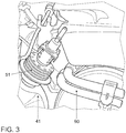
- the metering module 51 of the reduction catalyst 50 is connected to the connecting module 40 and to the housing.
- the invention is preferably applied to a transversely mounted or built-diesel engine.
- FIGS. 4 and 5 the expedient embodiment of the housing 41 of the connecting module 40 is shown in order to carry out the reduction in this module 40. It is apparent that essentially only the metering module 51 is to be arranged on the connecting module 40 in order to realize the reduction.
- FIG. 6 It can be seen in which area the actual reduction is realized.
- the exhaust gas flows in the exhaust gas path 22 along the exhaust gas flow direction 23 through the oxidation catalyst 30 and from there into the housing 41.
- the dosing module 51 of the reduction catalytic converter 50 attached to this housing 41 allows the introduction of the reducing agent into the hot exhaust gas to realize the reduction.
- the introduction of the reducing agent through the metering module 51 is preferably carried out by an injection 53, as indicated in the cavity of the housing 41.
- a cooling unit 52 on the dosing module 51 can be fluidically connected to a cooling device of the combustion unit 10 and / or connected to a cooling device of a low-pressure exhaust gas recirculation device 70.
- the arrangement of such a low-pressure exhaust gas recirculation device 70 is FIG. 7 removable. It can be seen that the low-pressure exhaust gas recirculation device 70 in the exhaust path 22 connects to the particle filter 60.
- the low-pressure exhaust gas recirculation device 70 advantageously has a cooling device 80 which, as already described, can be connected to the cooling unit 52 of the metering module 51 of the reduction catalytic converter 50. With a suitable design of the cooling device 80 of the combustion unit 10 or the low-pressure exhaust gas recirculation device 70, the metering module 51 of the reduction catalyst 50 can be Cool in a simple and efficient way, even without space consuming consuming additional cooling units on the reduction catalyst 50 provided.
- the reduction catalyst 50 is preferably to be arranged in the engine compartment of the motor vehicle 100, as close as possible to the combustion unit 10. That is, the reduction catalyst 50 is disposed above the motor vehicle underbody 110.
Description
Die vorliegende Erfindung betrifft eine Abgasbehandlungseinrichtung zur Aufbereitung von Abgas eines Verbrennungsaggregats, insbesondere eines Dieselmotors. Weiterhin betrifft die vorliegende Erfindung ein Verfahren zur Aufbereitung von Abgas eines Verbrennungsaggregats durch selektive katalytische Reaktion, sowie ein Kraftfahrzeug, in dem das erfindungsgemäße Verfahren realisiert wird beziehungsweise welches die erfindungsgemäße Abgasbehandlungseinrichtung aufweist.The present invention relates to an exhaust gas treatment device for the treatment of exhaust gas of a combustion unit, in particular a diesel engine. Furthermore, the present invention relates to a method for the treatment of exhaust gas of a combustion aggregate by selective catalytic reaction, as well as a motor vehicle in which the inventive method is realized or which has the exhaust gas treatment device according to the invention.
Eine gründliche und effiziente Reinigung der Abgase einer Verbrennungskraftmaschine kann durch die Zugabe eines Reduktionsmittels zum Abgas in einer Abgasnachbehandlungseinrichtung erfolgen. Dabei werden insbesondere bei mager betriebenen Verbrennungskraftmaschinen, bei denen für die Verbrennung ein Luftüberschuss gegenüber einem stöchiometrischen Kraftstoff-Luft-Gemisch vorliegt, die Stickoxidverbindungen im Abgas reduziert. Als Reaktionsmittel wird üblicherweise Ammoniak verwendet. Bei ausreichenden Temperaturen des Abgases werden die Stickoxidverbindungen zusammen mit dem Ammoniak zu unschädlichen Bestandteilen wie Wasser und Stickstoff reduziert.Thorough and efficient cleaning of the exhaust gases of an internal combustion engine can be achieved by the addition of a reducing agent to the exhaust gas in an exhaust aftertreatment device. In particular, in lean-burn internal combustion engines in which there is an excess of air over a stoichiometric fuel-air mixture for combustion, the nitrogen oxide compounds in the exhaust gas are reduced. As the reaction agent, ammonia is usually used. At sufficient temperatures of the exhaust gas, the nitrogen oxide compounds are reduced together with the ammonia to harmless components such as water and nitrogen.
Üblicherweise erfolgt die Zugabe des Reduktionsmittels aufgrund von beengten Bauraumverhältnissen im Motorbereich an einem Kraftfahrzeug in dessen Unterbodenbereich und somit in dem dort verlaufenden Abgasstrang. Oftmals werden dabei zweiteilige Reduktionskatalysatoren oder auch zwei voneinander getrennte Reduktionskatalysatoren im Unterbodenbereich angeordnet. Dies bedingt einen gewissen Fertigungs- und Montageaufwand sowie einen erhöhten Energiebedarf, um die im Unterbodenbereich angeordneten Katalysatoren auf die erforderliche Betriebstemperatur zu bringen. Üblicherweise wird dies durch eine elektrische Heizung an oder in den Reduktionskatalysatoren realisiert, oder durch eine so genannte verschleppte Verbrennung von Treibstoff im Verbrennungsmotor. Das bedeutet, dass der Verbrennungsmotor die chemische Energie des Treibstoffes nicht optimal in Bewegungsenergie des Kraftfahrzeuges umsetzen kann. Zudem sind lediglich zirka 400 °C bis 450 °C durch die verschleppte Verbrennung von Treibstoff in den Reduktionskatalysatoren erreichbar.Usually, the addition of the reducing agent takes place due to confined space conditions in the engine area on a motor vehicle in the underbody area and thus in the exhaust line extending there. Often, two-part reduction catalysts or even two separate reduction catalysts are arranged in the underfloor region. This requires a certain production and assembly costs and an increased energy requirement to bring the arranged in the underbody catalyst to the required operating temperature. Usually, this is realized by an electric heater on or in the reduction catalysts, or by a so-called delayed combustion of fuel in the internal combustion engine. This means that the internal combustion engine can not optimally convert the chemical energy of the fuel into kinetic energy of the motor vehicle. In addition, only about 400 ° C to 450 ° C can be reached by the delayed combustion of fuel in the reduction catalysts.
Die Zuführung von Wärme zu den Reduktionskatalysatoren dient zum einen zur Erwärmung des Abgases zwecks Realisierung der erforderlichen Reduktion und zum anderen zur Erwärmung des Reduktionsmittels, um den dort enthaltenen Wasseranteil möglichst schnell in eine Gasphase zu versetzen.The supply of heat to the reduction catalysts serves on the one hand to heat the exhaust gas in order to realize the required reduction and on the other to heat the reducing agent in order to put the water content contained there as quickly as possible in a gas phase.
Aus der
Auch aus der
Die
Die
Die
Die
Im Dokument
Der vorliegenden Erfindung liegt die Aufgabe zugrunde, eine Einrichtung sowie ein Verfahren zur Verfügung zu stellen, mit denen in effizienter und kostengünstiger Weise die Stickoxidverbindungen im Abgas reduziert werden können.The present invention has for its object to provide a device and a method available with which the nitrogen oxide compounds in the exhaust gas can be reduced in an efficient and cost-effective manner.
Diese Aufgabe wird durch die erfindungsgemäße Abgasbehandlungseinrichtung nach Anspruch 1 sowie das erfindungsgemäße Verfahren zur Aufbereitung von Abgas eines Verbrennungsaggregats nach Anspruch 10 gelöst. Ergänzend wird gemäß Anspruch 13 ein Kraftfahrzeug vorgeschlagen, welches eine erfindungsgemäße Abgasbehandlungseinrichtung umfasst.This object is achieved by the exhaust gas treatment device according to the invention according to claim 1 and the inventive method for the treatment of exhaust gas of a combustion unit according to
Es wird erfindungsgemäß Abgasbehandlungseinrichtung zur Aufbereitung von Abgas eines Verbrennungsaggregats, insbesondere eines Dieselmotors, zur Verfügung gestellt, wobei die Abgasbehandlungseinrichtung einen Abgasstrang mit einer Anschlusseinrichtung zum Anschließen des Abgasstranges am Verbrennungsaggregat umfasst und darin angeordnet einen Oxidationskatalysator, einen Reduktionskatalysator zur selektiven katalytischen Reduktion und einen Partikelfilter aufweist, wobei der Oxidationskatalysator stromaufwärts des Reduktionskatalysators und der Reduktionskatalysator stromaufwärts des Partikelfilters angeordnet ist. Ein Dosiermodul ist zwischen dem Oxidationskatalysator und dem Reduktionskatalysator angeordnet, wobei der Oxidationskatalysator, das Dosiermodul, der Reduktionskatalysator und der Partikelfilter an einer Seite des Verbrennungsaggregates angeordnet sind. Es ist erfindungsgemäß vorgesehen, dass der Reduktionskatalysator im Abgasstrang in Abgas-Strömungsrichtung derart weit stromaufwärts angeordnet ist, dass die Wärme des den Reduktionskatalysator passierenden Abgases ausreicht, um den Reduktionskatalysator auf Betriebstemperatur zu bringen. Der Partikelfilter ist dabei auf einer vertikalen Höhe tiefer als die Anschlussreinrichtung an der Seite des Verbrennungsaggregates angeordnet. Das Dosiermodul ist in einem verbindenden Modul angeordnet und der Oxidationskatalysator auf einer vertikalen Höhe auf der Höhe der Anschlusseinrichtung angeordnet ist Die Wärme des den Reduktionskatalysator passierenden Abgases ist dabei die Wärme des Abgases des Verbrennungsaggregats, gegebenenfalls abzüglich etwaiger Wärmeverluste durch den Transport des Abgases vom Verbrennungsaggregat zum Reduktionskatalysator. Die Abgaswärme ist somit die Wärme, die bei der exothermen Verbrennung des Kraftstoffes im Verbrennungsaggregat entsteht. Die Erfindung hat somit den Vorteil, dass die Temperatur des Abgases nach der exothermen Reaktion im Verbrennungsaggregat zur Zersetzung des Reduktionsmittels Ammoniak genutzt werden kann, sowie zur Reduktion von Stickstoffverbindungen zusammen mit Ammoniak zu unschädlichen Stoffen wie Wasser und Stickstoff. Der Reduktionskatalysator ist dabei bevorzugt ein so genannter SCR-Katalysator (selective catalytic reduction), der ein Reduktionsmittel, wie zum Beispiel Harnstoff, beziehungsweise einen Reduktionsmittel-Vorläufer, wie zum Beispiel eine Harnstoff-Wasser-Lösung, in Ammoniak umsetzt, welches dann katalytisch mit Stickoxiden selektiv zu Stickstoff und Wasser konvertiert wird. Dadurch lässt sich der Ausstoß von Stickoxiden um bis zu 90 % verringern.According to the invention, exhaust gas treatment device is provided for the treatment of exhaust gas of a combustion unit, in particular a diesel engine, wherein the exhaust gas treatment device comprises an exhaust gas line with a connection device for connecting the exhaust line to the combustion unit and having therein an oxidation catalyst, a reduction catalyst for selective catalytic reduction and a particle filter wherein the oxidation catalyst is disposed upstream of the reduction catalyst and the reduction catalyst is disposed upstream of the particulate filter. A metering module is disposed between the oxidation catalyst and the reduction catalyst, wherein the oxidation catalyst, the metering module, the reduction catalyst and the particulate filter are arranged on one side of the combustion aggregate. It is inventively provided that the reduction catalyst is arranged in the exhaust line in the exhaust gas flow direction so far upstream that the heat of the exhaust catalyst passing exhaust sufficient to bring the reduction catalyst to operating temperature. The particle filter is arranged at a vertical height deeper than the connecting device on the side of the combustion unit. The heat of the exhaust gas passing through the reduction catalytic converter is the heat of the exhaust gas of the combustion aggregate, optionally less any heat losses due to the transport of the exhaust gas from the combustion aggregate to the combustion unit Reduction catalyst. The exhaust gas heat is thus the heat that arises during the exothermic combustion of the fuel in the combustion unit. The invention thus has the advantage that the temperature of the exhaust gas after the exothermic reaction in the combustion unit for decomposition of the reducing agent ammonia can be used, as well as for the reduction of nitrogen compounds together with ammonia to harmless substances such as water and nitrogen. The reduction catalyst is preferably a so-called SCR catalyst (selective catalytic reduction), which converts a reducing agent, such as urea, or a reducing agent precursor, such as a urea-water solution in ammonia, which then catalytically with Nitrogen oxides is selectively converted to nitrogen and water. As a result, the emission of nitrogen oxides can be reduced by up to 90%.
Dabei kann es vorgesehen sein, dass die Abgasströmungsrichtung von einem Eintritt in den Oxidationskatalysator bis zu einem Austritt aus dem Partikelfilter im Wesentlichen eine Umlenkung von 180 ° erfährt.It may be provided that the exhaust gas flow direction from an entry into the oxidation catalyst to a discharge from the particulate filter substantially undergoes a deflection of 180 °.
Erfindungsgemäß kann der Abgaspfad in Abgasströmungsrichtung vom Eintritt in den Oxidationskatalysator bis zum Austritt aus dem Partikelfilter eine U-Form beschreiben.According to the invention, the exhaust gas path in the exhaust gas flow direction from entry into the oxidation catalyst to the exit from the particle filter can describe a U-shape.
Dabei kann bevorzugt der Abgaspfad auf den Schenkeln der U-Form parallel zur Längsausdehnung des Verbrennungsaggregats verlaufen.In this case, preferably, the exhaust gas path on the legs of the U-shape run parallel to the longitudinal extent of the combustion unit.
In einer bevorzugten Ausführungsform können der Oxidationskatalysator und der Partikelfilter je in einem separaten Gehäuse untergebracht sein.In a preferred embodiment, the oxidation catalyst and the particulate filter can each be housed in a separate housing.
Das Dosiermodul kann in einer bevorzugten Ausführungsform auf der vertikalen Höhe des Oxidationskatalysators in dem verbindenden Modul angeordnet sein.The dosing module can be arranged in a preferred embodiment on the vertical height of the oxidation catalyst in the connecting module.
Ein solcher Reduktionskatalysator ist erfindungsgemäß im Abgasstrang in Abgas-Strömungsrichtung derart weit stromaufwärts angeordnet, dass die Wärme des den Reduktionskatalysator passierenden Abgases ausreicht, um eine Zersetzung des Reduktionsmittels zu realisieren und/oder eine Reduktion von Stickstoffverbindungen zusammen mit Ammoniak zu den genannten unschädlichen Stoffen wie Wasser und Stickstoff durchzuführen. Durch die erfindungsgemäße Anordnung des Reduktionskatalysators stromabwärts des Oxidationskatalysators ergibt sich der Vorteil der zusätzlichen Ausnutzung der Wärme des Abgases nach der exothermen Reaktion im Oxidationskatalysator. Das heißt, dass der Oxidationskatalysator im Betriebszustand die Temperatur des Abgases ebenfalls erhöht, so dass der nachgeschaltete Reduktionskatalysator noch effizienter betreibbar ist.According to the invention, such a reduction catalytic converter is arranged in the exhaust gas line in the exhaust gas flow direction so far upstream that the heat of the exhaust gas passing through the reduction catalytic converter is sufficient to realize a decomposition of the reducing agent and / or a reduction of nitrogen compounds together with ammonia to said harmless substances such as water and nitrogen. The inventive arrangement of the reduction catalyst downstream of the oxidation catalyst, there is the advantage of the additional utilization of the heat of the exhaust gas after the exothermic reaction in the oxidation catalyst. That is, the oxidation catalyst in the operating state, the temperature of the exhaust gas also increases, so that the downstream reduction catalyst is more efficient operable.
Durch die optimale Reduktion im Reduktionskatalysator gelangen aufbereitete Abgase in den nachgeschalteten Partikelfilter.Due to the optimal reduction in the reduction catalytic converter, treated exhaust gases pass into the downstream particle filter.
Des Weiteren kann zusätzlich ein Abgasturbolader im Abgasstrang angeordnet sein, wobei in diesem Falle der Reduktionskatalysator stromaufwärts des Abgasturboladers angeordnet ist, da dort die Temperatur des Abgases höher ist als an einer Position stromabwärts des Abgasturboladers.Furthermore, an exhaust gas turbocharger may additionally be arranged in the exhaust gas line, in which case the reduction catalytic converter is arranged upstream of the exhaust gas turbocharger, since there the temperature of the exhaust gas is higher than at a position downstream of the exhaust gas turbocharger.
Es lässt sich eine Wirkungsgradverbesserung bis auf zirka 90 % des Reduktionskatalysators erreichen, da nicht mehr eine herkömmliche elektrische Aufheizung des Reduktionsmittels oder eine verschleppte Verbrennung notwendig ist, so dass insgesamt der CO2-Ausstoß verringert werden kann und/oder weniger Kraftstoff einzusetzen ist.It can be an efficiency improvement to reach about 90% of the reduction catalyst, since no longer a conventional electrical heating of the reducing agent or a delayed combustion is necessary, so that the overall CO 2 emissions can be reduced and / or less fuel is used.
In bevorzugten Ausführungsformen ist vorgesehen, der der Reduktionskatalysator derart weit stromaufwärts angeordnet ist, dass das den Reduktionskatalysator passierende Abgas noch wenigstens 40 % und in besonders bevorzugter Ausführungsform wenigstens 80 % der Temperatur aufweist, die das Abgas direkt nach der Verbrennung im Verbrennungsaggregat hat. Die Erfindung betrifft somit eine Abgasbehandlungseinrichtung, die, wenn sie an ein Verbrennungsaggregat angeschlossen ist, von Abgas durchströmt ist, wobei das Abgas, welches am Reduktionskatalysator entlang strömt, noch wenigstens 40 % der Temperatur hat, die das Abgas direkt nach der Verbrennung im Verbrennungsaggregat aufweist. Vorzugsweise sollte die Position des Reduktionskatalysators so dicht am Verbrennungsaggregat sein, dass das den Reduktionskatalysator passierende Abgas eine Temperatur von mindestens 60 % und bevorzugt mindestens 80 % und in besonders günstiger Ausgestaltung mindestens 90 % der Temperatur des Abgases direkt nach der Verbrennung im Verbrennungsaggregat hat.In preferred embodiments it is provided that the reduction catalytic converter is arranged so far upstream that the exhaust gas passing through the reduction catalytic converter still has at least 40% and in a particularly preferred embodiment at least 80% of the temperature which the exhaust gas has directly after combustion in the combustion unit. The invention thus relates to an exhaust gas treatment device, which, when it is connected to a combustion unit, is flowed through by exhaust gas, wherein the exhaust gas flowing along the reduction catalyst, at least 40% of the temperature having the exhaust gas directly after combustion in the combustion unit , The position of the reduction catalytic converter should preferably be so close to the combustion unit that the exhaust gas passing through the reduction catalytic converter has a temperature of at least 60% and preferably at least 80% and in a particularly favorable embodiment at least 90% of the temperature of the exhaust gas directly after combustion in the combustion unit.
Der Abgasstrang, in dem der Reduktionskatalysator angeordnet ist, weist eine Anschlusseinrichtung zum Anschließen des Abgasstranges am Verbrennungsaggregat auf, so dass der Reduktionskatalysator so dicht wie möglich am Verbrennungsaggregat angeordnet werden kann. Dabei kann der Abgasstrang einfache Leitungsstücke oder auch weitere Aggregate, wie zum Beispiel weitere Katalysatoren, aufweisen. Durch die erfindungsgemäße Ausgestaltung des Abgasstranges ergibt sich der Vorteil des konstruktiv einfacheren Verlaufs der Abgasanlage am Unterboden eines Kraftfahrzeuges, da am Unterboden beziehungsweise unter dem Unterboden kein Reduktionskatalysator mehr angeordnet werden muss.The exhaust gas line, in which the reduction catalytic converter is arranged, has a connection device for connecting the exhaust gas line to the combustion unit, so that the reduction catalytic converter can be arranged as close as possible to the combustion unit. In this case, the exhaust gas line simple line pieces or other aggregates, such as other catalysts have. Due to the inventive design of the exhaust line, there is the advantage of structurally simpler course of the exhaust system on the underbody of a motor vehicle, since no reduction catalyst must be arranged on the subfloor or under the subfloor.
Durch die erfindungsgemäße frühzeitige Ausnutzung der hohen Temperatur des Abgases ist es möglich, schon wesentlich früher als bisher praktiziert Reduktionsmittel in das Abgas einzubringen und somit früher als bei herkömmlichen Reduktionsverfahren die Stickstoffverbindungen umzuwandeln. Durch die erfindungsgemäße frühe Einbringung des Reduktionsmittels in das Abgas lässt sich optimal eine frühe Homogenisierung des Abgases, das heißt eine gleichmäßige Verteilung des Reduktionsmittels im Abgas, erreichen, so dass die Reduktion effizient realisiert werden kann.By early utilization of the high temperature of the exhaust gas according to the invention, it is possible to introduce reducing agent into the exhaust gas much earlier than previously practiced, and thus to convert the nitrogen compounds earlier than in conventional reduction processes. The early introduction of the reducing agent into the exhaust gas according to the invention makes it possible optimally to achieve an early homogenization of the exhaust gas, that is to say a uniform distribution of the reducing agent in the exhaust gas, so that the reduction can be realized efficiently.
Außerdem kann thermische Energie des Verbrennungsaggregates genutzt werden, welche mittels Wärmestrahlung über die Umgebungsluft und/oder mittels Wärmeleitung im festen Material des an das Verbrennungsaggregat angeschlossenen Abgasstrangs zum Reduktionskatalysator gelangt, so dass die Temperatur des Abgases mindestens die bevorzugten 40 % und vorzugsweise über 80 % der Temperatur des Abgases unmittelbar nach dem Verbrennungsprozess beträgt. Durch die effiziente Betriebsweise des dicht am Verbrennungsaggregat angeordneten Reduktionskatalysators ist lediglich ein Reduktionskatalysator erforderlich, wodurch zusätzlich Volumen im Unterbodenbereich gewonnen beziehungsweise zur Verfügung gestellt wird und die Montage des Abgasstranges erleichtert wird.In addition, thermal energy of the combustion unit can be used, which passes by heat radiation through the ambient air and / or by heat conduction in the solid material of the combustion unit connected to the exhaust gas to the reduction catalyst, so that the temperature of the exhaust gas at least the preferred 40% and preferably over 80% of Temperature of the exhaust gas immediately after the combustion process is. As a result of the efficient mode of operation of the reduction catalytic converter arranged close to the combustion unit, only one reduction catalytic converter is required, as a result of which additional volume in the underfloor region is obtained or made available and assembly of the exhaust line is facilitated.
In einer bevorzugten Ausgestaltung der Abgasbehandlungseinrichtung ist vorgesehen, dass der Reduktionskatalysator ein Dosiermodul zur dosierten Einbringung des Reduktionsmittels aufweist, wobei das Dosiermodul eine von einem Kühlmedium durchströmbare Kühlungseinheit aufweist und derart ausgestaltet und ausgelegt ist, dass die Kühlungseinheit strömungstechnisch mit einer Kühleinrichtung des Verbrennungsaggregats verbindbar ist, so dass Kühlmedium von der Kühlungseinrichtung zur Kühlung des Dosiermoduls nutzbar ist. Die Einbringung des Reduktionsmittels erfolgt bevorzugt durch Einspritzung. Das Dosiermodul wird durch die hohe Temperatur des Abgases erwärmt, wobei die bereits genannten Vorteile generiert werden. Das Dosiermodul kann zur Erleichterung und der Realisierung der Einspritzung des Reduktionsmittels gekühlt werden. Eine Kühlung ist insbesondere dann notwendig, wenn eine Erwärmung des Dosiermoduls über 80 °C zu erwarten ist, welche zu einer vorzeitigen Alterung des Harnstoffes führt. Aus fertigungstechnischen Gründen sowie hinsichtlich der Gewichtsoptimierung ist die Abgasbehandlungseinrichtung vorteilhaft ausgestaltet, wenn eine Kühleinrichtung des Verbrennungsaggregates das Dosiermodul ebenfalls mit Kühlmedium speisen kann. Bei Verwendung eines Dieselmotors als Verbrennungsaggregat kann die Kühlungseinheit des Dosiermoduls an die Kühlung des Motors angeschlossen sein, wodurch sich eine einfache und effiziente sowie gewichts- und volumensparende Kühlung des Dosiermoduls erreichen lässt.In a preferred refinement of the exhaust-gas treatment device, it is provided that the reduction catalytic converter has a dosing module for the metered introduction of the reducing agent, wherein the dosing module has a cooling unit through which a cooling medium flows and is designed and configured such that the cooling unit can be fluidically connected to a cooling device of the combustion unit, so that cooling medium can be used by the cooling device for cooling the metering module. The introduction of the reducing agent is preferably carried out by injection. The metering module is heated by the high temperature of the exhaust gas, the advantages already mentioned are generated. The dosing module can be cooled to facilitate and realize the injection of the reducing agent. Cooling is necessary in particular if heating of the metering module above 80 ° C. is to be expected, which leads to premature aging of the urea. For manufacturing reasons and in terms of weight optimization, the exhaust gas treatment device is advantageously configured when a cooling device of the combustion unit can also feed the dosing with cooling medium. When using a diesel engine as a combustion unit, the cooling unit of the metering module to the cooling of the engine be connected, which can be a simple and efficient as well as weight and volume-saving cooling of the dosing achieved.
Weiterhin kann insbesondere zum Zweck der Volumenverringerung vorgesehen sein, dass der Reduktionskatalysator an einem den Oxidationskatalysator mit dem Partikelfilter verbindenden Modul angeordnet ist. Dieses Modul kann ein so genannter Verbindungstrichter sein. Ein solches Modul ist kostengünstig herstellbar und erlaubt in einfacher Weise eine platzsparende Anordnung des Dosiermoduls des Reduktionskatalysators.Furthermore, it can be provided, in particular for the purpose of reducing the volume, that the reduction catalytic converter is arranged on a module connecting the oxidation catalytic converter with the particle filter. This module can be a so-called connection funnel. Such a module is inexpensive to produce and allows in a simple manner a space-saving arrangement of the dosing of the reduction catalyst.
Diese Ausführungsform der Erfindung ist insbesondere dann vorteilhaft ausgestaltet, wenn das Modul ein vom Abgas durchströmbares Gehäuse aufweist, welches als Gehäuse des Reduktionskatalysators dient. In dieser Ausführungsform kann eine Einspritzung des Reduktionsmittels direkt in das Gehäuse beziehungsweise in das Modul erfolgen.This embodiment of the invention is particularly advantageous when the module has a flow-through by the exhaust gas housing, which serves as a housing of the reduction catalyst. In this embodiment, an injection of the reducing agent can be carried out directly in the housing or in the module.
In alternativer Ausgestaltung kann vorgesehen sein, dass der Reduktionskatalysator direkt am Partikelfilter angeordnet ist. Das heißt, dass der Partikelfilter und der Reduktionskatalysator zusammen eine bauliche Einheit ausbilden, die insgesamt ein geringes Volumen aufweist, da das Gehäuse des Partikelfilters teilweise auch als Gehäuse des Reduktionskatalysators verwendet wird.In an alternative embodiment, it may be provided that the reduction catalytic converter is arranged directly on the particle filter. That is, the particulate filter and the reduction catalyst together form a structural unit having a small volume as a whole because the housing of the particulate filter is also partially used as the housing of the reduction catalyst.
Weiterhin weist die erfindungsgemäße Abgasbehandlungseinrichtung eine Niederdruck-Abgasrückführungseinrichtung auf. Diese Kombination der erfindungsgemäßen Abgasbehandlungseinrichtung mit einer Niederdruck-Abgasrückführungseinrichtung hat den Vorteil der einfachen und kostengünstigen Abgasführung vom Reduktionskatalysator zur Niederdruck-Abgasrückführungseinrichtung, im Gegensatz zu herkömmlichen Ausführungsformen mit dem Reduktionskatalysator am Unterboden eines Kraftfahrzeuges, bei denen erhöhter baulicher Aufwand zur Abgasführung vom Reduktionskatalysator zur Niederdruck-Abgasrückführungseinrichtung anfällt. Eine Niederdruck-Abgasrückführungseinrichtung hat gegenüber einer Hochdruck-Abgasrückführungseinrichtung den Vorteil, dass der gesamte Abgasmassenstrom über eine Turbine für die Leistungsentwicklung zur Verfügung steht. Bei einer Hochdruck-Abgasrückführungseinrichtung wird ein Abgasmassenstrom vor der Turbine entnommen und dem Aggregat wieder zugeführt. Dieser Massenstrom kann nicht mehr zum Aufbau des Ladedrucks genutzt werden.Furthermore, the exhaust gas treatment device according to the invention has a low-pressure exhaust gas recirculation device. This combination of the exhaust gas treatment device according to the invention with a low-pressure exhaust gas recirculation device has the advantage of simple and cost-effective exhaust gas from the reduction catalytic converter to the low-pressure exhaust gas recirculation device, in contrast to conventional embodiments with the reduction catalyst on the underbody of a motor vehicle, in which increased structural complexity for the exhaust system from the reduction catalytic converter to the low pressure Exhaust gas recirculation device is obtained. A low-pressure exhaust gas recirculation device has the advantage over a high-pressure exhaust gas recirculation device that the entire exhaust gas mass flow is available via a turbine for the development of power. In a high-pressure exhaust gas recirculation device, an exhaust gas mass flow upstream of the turbine is removed and returned to the unit. This mass flow can no longer be used to build up the boost pressure.
In vorteilhafter Ausführungsform weist die Niederdruck-Abgasrückführungseinrichtung eine Kühleinrichtung auf, die derart wärmetechnisch mit dem Dosiermodul des Reduktionskatalysators verbunden ist, dass mittels der Kühleinrichtung der Niederdruck-Abgasrückführungseinrichtung das Dosiermodul kühlbar ist. Dabei lässt sich eine direkte oder indirekte Kühlung realisieren. Bei einer direkten Kühlung ist eine unmittelbare thermische Kopplung zwischen der Kühleinrichtung und dem Dosiermodul vorgesehen. Bei einer indirekten Kühlung wird zumindest ein Teilstrom eines Kühlmediums der Kühleinrichtung dem Dosiermodul zugeleitet. Somit ist eine vollständige oder teilweise Kühlung des Dosiermoduls möglich.In an advantageous embodiment, the low-pressure exhaust gas recirculation device to a cooling device, which is so thermally with the dosing of the Reduction catalyst is connected, that by means of the cooling device of the low-pressure exhaust gas recirculation device, the metering module is cooled. In this case, a direct or indirect cooling can be realized. In a direct cooling an immediate thermal coupling between the cooling device and the metering module is provided. In an indirect cooling at least a partial flow of a cooling medium of the cooling device is fed to the dosing. Thus, a complete or partial cooling of the dosing is possible.
Es wird außerdem erfindungsgemäß ein Verfahren zur Aufbereitung von Abgas eines Verbrennungsaggregats durch selektive katalytische Reduktion zur Verfügung gestellt, insbesondere zur Aufbereitung von Abgas eines Dieselmotors. Dabei strömt das Abgas durch einen mit dem Verbrennungsaggregat gekoppelten Abgasstrang, wobei in dem Abgasstrang ein Oxidationskatalysator stromaufwärts eines zur selektiven katalytischen Reduktion vorgesehenen Reduktionskatalysators und der Reduktionskatalysator stromaufwärts eines Partikelfilters angeordnet ist und die Wärme des den Reduktionskatalysator passierenden Abgases genutzt wird, um den Reduktionskatalysator auf Betriebstemperatur zu erwärmen. Dabei ist der Abgasstrang mit einer Anschlusseinrichtung an dem Verbrennungsaggregat angeschlossen. Außerdem ist ein Dosiermodul zwischen dem Oxidationskatalysator und dem Reduktionskatalysator angeordnet. Wobei der Oxidationskatalysator, das Dosiermodul, der Reduktionskatalysator und der Partikelfilter an einer Seite des Verbrennungsaggregates angeordnet sind. Der Partikelfilter ist auf einer vertikalen Höhe tiefer als die Anschlussreinrichtung an der Seite des Verbrennungsaggregates angeordnet und die Anschlusseinrichtung, der Oxidationskatalysator, das verbindende Modul, der Reduktionskatalysator und der Partikelfilter werden von dem durchströmenden Abgas auf dem Abgaspfad passiert. Das Abgas passiert auf dem Abgaspfad den Oxidationskatalysator auf einer vertikalen Höhe auf der Höhe der Anschlusseinrichtung. Das Dosiermodul führt dabei in einem verbindenden Modul eine Einspritzung in den Abgaspfad durch. Die Wärme des Abgases wird dabei zur Erwärmung des Reduktionskatalysators aus dem kalten Zustand sowie zur Aufrechterhaltung der Betriebstemperatur genutzt. Es kann dabei vorgesehen sein, dass ausschließlich Wärme des den Reduktionskatalysator passierenden Abgases genutzt wird, um den Reduktionskatalysator auf Betriebstemperatur zu bringen beziehungsweise zu halten. Als Reduktionsmittel kann dabei ein Reduktionsmittelvorläufer, wie zum Beispiel gasförmiges Ammoniak, oder auch eine Reduktionsmittelvorläuferlösung, wie zum Beispiel auch eine wässrige Lösung mit gelöstem Harnstoff, genutzt werden. Vorzugsweise sollte das den Reduktionskatalysator passierende Abgas eine Temperatur von mindestens 40 %, insbesondere 60 % und in besonderer Ausführungsform mindestens 80 % und bestmöglich mindestens 90 % der Temperatur des Abgases direkt nach der Verbrennung im Verbrennungsaggregat haben. Das heißt, dass das Abgas nach dem Austritt aus dem Verbrennungsaggregat nicht noch einmal elektrisch erwärmt wird, sondern die Temperatur des Abgases ausschließlich auf die exotherme Reaktion im Verbrennungsprozess im Verbrennungsaggregat und/oder im Oxidationskatalysator zurückzuführen ist. Eine geringere der Temperatur des Abgases im Reduktionskatalysator ist demzufolge lediglich auf eine Wärmeübertragung auf die Umgebung des Abgasstranges stromabwärts des Verbrennungsaggregates zurückzuführen.It is also provided according to the invention a method for the treatment of exhaust gas of a combustion unit by selective catalytic reduction available, in particular for the treatment of exhaust gas of a diesel engine. In this case, the exhaust gas flows through an exhaust line coupled to the combustion unit, wherein in the exhaust line, an oxidation catalyst upstream of a selective catalytic reduction reduction catalyst and the reduction catalyst upstream of a particulate filter is arranged and the heat of the reduction catalyst passing exhaust gas is used to the reduction catalyst to operating temperature to warm up. In this case, the exhaust gas line is connected to a connection device to the combustion unit. In addition, a metering module is disposed between the oxidation catalyst and the reduction catalyst. Wherein the oxidation catalyst, the dosing module, the reduction catalyst and the particulate filter are arranged on one side of the combustion aggregate. The particulate filter is located at a vertical height lower than the connecting device on the side of the combustion unit and the connection device, the oxidation catalyst, the connecting module, the reduction catalyst and the particulate filter are passed by the flowing exhaust gas on the exhaust path. The exhaust gas passes through the oxidation catalyst on the exhaust path at a vertical height at the level of the connection device. The metering module performs an injection into the exhaust gas path in a connecting module. The heat of the exhaust gas is used to heat the reduction catalyst from the cold state and to maintain the operating temperature. It can be provided that only heat of the exhaust gas passing through the reduction catalyst is used to bring the reduction catalyst to operating temperature or to keep. In this case, a reducing agent precursor, such as, for example, gaseous ammonia, or else a reducing agent precursor solution, such as, for example, an aqueous solution with dissolved urea, can be used as the reducing agent. Preferably, the exhaust gas passing through the reduction catalyst should have a temperature of at least 40%, in particular 60% and in particular embodiment at least 80% and best possible have at least 90% of the temperature of the exhaust gas directly after combustion in the combustion unit. That is, the exhaust gas after exiting the combustion unit is not heated again electrically, but the temperature of the exhaust gas is due solely to the exothermic reaction in the combustion process in the combustion unit and / or in the oxidation catalyst. A lower temperature of the exhaust gas in the reduction catalyst is therefore due only to a heat transfer to the environment of the exhaust line downstream of the combustion unit.
Das Reduktionsmittel kann dabei direkt in den Partikelfilter oder in ein Modul eingebracht werden, welches den Oxidationskatalysator mit dem Partikelfilter strömungstechnisch verbindet. Das Reduktionsmittel kann an diesen Stellen durch Einspritzung in das Abgas eingebracht werden.The reducing agent can be introduced directly into the particle filter or into a module which fluidly connects the oxidation catalyst with the particle filter. The reducing agent can be introduced at these points by injection into the exhaust gas.
Erfindungsgemäß wird außerdem ein Kraftfahrzeug zur Verfügung gestellt, insbesondere ein dieselmotorisch betriebenes Kraftfahrzeug, welches eine erfindungsgemäße Abgasbehandlungseinrichtung aufweist. Dieses Kraftfahrzeug kann derart ausgestaltet sein, dass der Reduktionskatalysator ein Dosiermodul zur dosierten Einbringung des Reduktionsmittels aufweist, wobei das Dosiermodul eine von einem Kühlmodul durchströmbare Kühleinheit aufweist und strömungstechnisch mit einer Kühleinrichtung des Verbrennungsaggregats verbunden ist. Alternativ oder hinzukommend kann vorgesehen sein, dass die Kühlungseinheit des Dosiermoduls mit einem Kühler einer Abgasrückführungsanlage strömungstechnisch verbunden ist. In beiden Ausgestaltungsvarianten lässt sich eine bereits vorhandene Kühleinrichtung zur Kühlung des Dosiermoduls verwenden. In bevorzugter Ausführungsform des Kraftfahrzeuges ist dieses derart ausgestaltet, dass der Reduktionskatalysator oberhalb des Kraftfahrzeug-Unterbodens angeordnet ist. Bevorzugt weist das Kraftfahrzeug lediglich einen Reduktionskatalysator auf, nämlich den Reduktionskatalysator in der erfindungsgemäßen Abgasbehandlungseinrichtung, wobei der Reduktionskatalysator erfindungsgemäß sehr dicht am Motor und somit nicht mehr im Unterbodenbereich angeordnet ist.According to the invention, a motor vehicle is also provided, in particular a motor vehicle operated by diesel engine, which has an exhaust gas treatment device according to the invention. This motor vehicle can be designed such that the reduction catalytic converter has a metering module for metered introduction of the reducing agent, wherein the metering module has a cooling unit through which a cooling module can flow and is fluidically connected to a cooling device of the combustion unit. Alternatively or additionally, it may be provided that the cooling unit of the dosing module is fluidically connected to a cooler of an exhaust gas recirculation system. In both embodiments, an already existing cooling device can be used for cooling the dosing module. In a preferred embodiment of the motor vehicle, this is designed such that the reduction catalytic converter is arranged above the motor vehicle underbody. The motor vehicle preferably has only one reduction catalytic converter, namely the reduction catalytic converter in the exhaust gas treatment device according to the invention, wherein the reduction catalytic converter is arranged very close to the engine and thus no longer in the underbody region.
Die Erfindung wird nachfolgend in Ausführungsbeispielen anhand der zugehörigen Zeichnungen erläutert. Es zeigen:
- Figur 1
- ein Verbrennungsaggregat mit erfindungsgemäßer Abgasbehandlungseinrichtung in perspektivischer Ansicht;
- Figur 2
- einen vergrößerten Ausschnitt aus der in
Figur 1 dargestellten Abgasbehandlungseinrichtung; - Figur 3
- ein Dosiermodul eines Reduktionskatalysators;
- Figur 4
- den Reduktionskatalysator in Ansicht von der Seite;
- Figur 5
- den Oxidationskatalysator mit daran angeschlossenem Reduktionskatalysator in Ansicht von vorn;
- Figur 6
- den Oxidationskatalysator mit angeschlossenem Reduktionskatalysator in Schnittansicht;
- Figur 7
- eine erfindungsgemäße Abgasbehandlungseinrichtung mit integrierter Niederdruck-Abgasrückführungseinrichtung; und
- Figur 8
- ein Kraftfahrzeug in Ansicht von der Seite.
- FIG. 1
- a combustion unit with inventive exhaust gas treatment device in a perspective view;
- FIG. 2
- an enlarged section of the in
FIG. 1 illustrated exhaust treatment device; - FIG. 3
- a metering module of a reduction catalyst;
- FIG. 4
- the reduction catalyst in view from the side;
- FIG. 5
- the oxidation catalyst with connected reduction catalyst in front view;
- FIG. 6
- the oxidation catalyst with connected reduction catalyst in sectional view;
- FIG. 7
- an exhaust gas treatment device according to the invention with integrated low-pressure exhaust gas recirculation device; and
- FIG. 8
- a motor vehicle in view from the side.
In
Das heißt, dass der Reduktionskatalysator 50 am Gehäuse 41 des verbindenden Moduls 40 zwischen dem Oxidationskatalysator 30 und dem Partikelfilter 60 angeordnet ist.That is, the
Entgegen herkömmlichen Ausführungsformen ist somit der Reduktionskatalysator 50 sehr dicht am Verbrennungsaggregat 10 beziehungsweise an der Anschlusseinrichtung 21 angeordnet, so dass Wärme des Abgases, welches aus der exothermen Reaktion im Verbrennungsaggregat 10 entsteht, genutzt wird, um den Reduktionskatalysator 50 auf die erforderliche Betriebstemperatur zu bringen beziehungsweise ihn auf dieser Temperatur zu halten. Dabei kann zusätzlich auch die Wärme im Reduktionskatalysator 50 genutzt werden, die bei einer exothermen Reaktion im Oxidationskatalysator 30 freigesetzt wird, da der Reduktionskatalysator 50 unmittelbar an den Oxidationskatalysator 30 anschließt.Contrary to conventional embodiments, the
Wie
Wie in
In den
Aus
Die Anordnung einer solchen Niederdruck-Abgasrückführungseinrichtung 70 ist
Aus
- 1010
- Verbrennungsaggregatcombustion unit
- 2020
- Abgasstrangexhaust gas line
- 2121
- Anschlusseinrichtungconnecting device
- 2222
- Abgaspfadexhaust path
- 2323
- Abgas-StrömungsrichtungExhaust gas flow direction
- 3030
- Oxidationskatalysatoroxidation catalyst
- 4040
- verbindendes Modulconnecting module
- 4141
- Gehäusecasing
- 5050
- Reduktionskatalysatorreduction catalyst
- 5151
- Dosiermoduldosing
- 5252
- Kühlungseinheitcooling unit
- 5353
- Einspritzunginjection
- 6060
- Partikelfilterparticulate Filter
- 7070
- Niederdruck-AbgasrückführungseinrichtungLow-pressure exhaust gas recirculation device
- 8080
- Kühleinrichtungcooling device
- 9090
- Sammelleitungmanifold
- 100100
- Kraftfahrzeugmotor vehicle
- 110110
- Kraftfahrzeug-UnterbodenAutomotive underbody
Claims (14)
- An exhaust gas treatment device for treating exhaust gas of the combustion unit (10), comprising an exhaust gas system (20) with a connecting device (21) for connecting the exhaust gas system (20) to the combustion unit (10) and arranged in the exhaust gas system (20) an oxidation catalyst (30), a reduction catalyst (50) for the selective catalytic reduction and a particle filter (60), wherein the oxidation catalyst (30) is arranged upstream of the reduction catalyst (50) and the reduction catalyst (50) upstream of the particle filter (60) and a metering module (51) is arranged between the oxidation catalyst (30) and the reduction catalyst (50), wherein the reduction catalyst (50) is arranged far upstream in the exhaust gas system (20) in the direction of the exhaust gas flow (23) in such a manner that the heat of the exhaust gas passing through the reduction catalyst (50) suffices, in order to bring the reduction catalyst (50) to an operating temperature, wherein the metering module (51) is arranged in a connecting module (40) characterized in that, wherein the particle filter (60) is arranged at a vertical height lower than the connecting device (21) on the side of the combustion unit (10), wherein the oxidation catalyst (30), the metering module (51), the reduction catalyst (50) and the particle filter (60) are arranged on a side of the combustion unit (10) and the oxidation catalyst (30) is arranged at a vertical height at the height of the connecting device (21), wherein the exhaust gas treatment device furthermore has a low-pressure exhaust gas recirculation (70).
- The exhaust gas treatment device for treating exhaust gas according to Claim 1, characterized in that the direction of the exhaust gas flow (23) essentially undergoes a deflection of 180° from an entry into the oxidation catalyst (30) to an exit from the particle filter (60).
- The exhaust gas treatment device for treating exhaust gas according to Claim 1, characterized in that the exhaust gas path (22) in the direction of the exhaust gas flow (23) from the entry into the oxidation catalyst (30) to the exit from the particle filter (60) (60) describes a U-shape.
- The exhaust gas treatment device for treating exhaust gas according to Claim 1, characterized in that the exhaust as path (22) runs on the limbs of the U-shape parallel to the longitudinal extension of the combustion unit.
- The exhaust gas treatment device for treating exhaust gas according to Claim 1, characterized in that the oxidation catalyst (30) and the particle filter (60) are each accommodated in a separate housing.
- The exhaust gas treatment device for treating exhaust gas according to Claim 1, characterized in that the metering module (51) is arranged at a vertical height above the oxidation catalyst (30) in a connecting module (40).
- The exhaust gas treatment device for treating exhaust gas according to Claim 1, characterized in that the reduction catalyst (50) and the particle filter (60) together form a structural unit.
- The exhaust gas treatment device for treating exhaust gas according to Claim 7, characterized in that the reduction catalyst (50) is arranged directly on the particle filter (60).
- The exhaust gas treatment device for treating exhaust gas according to Claim 1, characterized in that a low-pressure exhaust gas recirculation device (70) comprises a cooling device (80), which is connected thermally with the metering module (51) of the reduction catalyst (50) in such a manner that by means of the cooling device (80) of the low-pressure exhaust gas recirculation device (70) the metering module (51) can be cooled.
- A method for treating exhaust gas of a combustion unit (10) by the selective catalytic reduction which flows through an exhaust gas system coupled with the combustion unit (10), wherein the exhaust gas system (20) is connected with a connecting device (21) to the combustion unit (10), wherein in the exhaust gas system (20) an oxidation catalyst (30) is arranged upstream of a reduction catalyst (50) provided for the selective catalytic reduction in a connecting module (40) and the reduction catalyst (50) is arranged upstream of a particle filter (60) and a metering module (51) is arranged between the oxidation catalyst (30) and the reduction catalyst (50), wherein the oxidation catalyst (30), the metering module (51), the reduction catalyst (50) and the particle filter (60) are arranged on a side of the combustion unit (10), wherein the reduction catalyst (50) is arranged far upstream in the exhaust gas system (20) in the direction of the exhaust gas flow (23) in such a manner that the heat of the exhaust gas passing through the reduction catalyst (50) is used, in order to bring the reduction catalyst (50) to an operating temperature, wherein the particle filter (60) is arranged at a vertical height lower than the connecting device (21) on the side of the combustion unit (10) and the connecting device, the oxidation catalyst (30), the connecting module (40), the reduction catalyst (50) and the particle filter (60) are passed through by the exhaust gas flowing through on an exhaust gas path (22), wherein the exhaust gas passes on the exhaust gas path (22) through the oxidation catalyst (30) at a vertical height at the height of the connecting device (21) and the metering module (51) in the connecting module (40) performs an injection (53) into the exhaust as path (22) and wherein the exhaust gas treatment device furthermore has a low-pressure exhaust gas recirculation (70).
- A motor vehicle with a combustion unit (10) with an exhaust gas treatment device according to any one of Claims 1 to 9.
- The motor vehicle according to Claim 11, characterized in that the reduction catalyst (50) has a metering module (51) for the metered introduction of the reducing agent, wherein the metering module (51) has a cooling unit (52) through which a cooling medium can flow and is connected fluidically to a cooling device (80) of the combustion unit (10).
- The motor vehicle according to any one of Claims 11 and 12, characterized in that the reduction catalyst (50) is arranged above the motor vehicle under body (110).
- The motor vehicle according to any one of Claims 11 to 13, characterized in that the motor vehicle can be operated by means of a diesel engine.
Applications Claiming Priority (3)
| Application Number | Priority Date | Filing Date | Title |
|---|---|---|---|
| DE102011111590A DE102011111590A1 (en) | 2011-08-25 | 2011-08-25 | Exhaust gas treatment device, process for the treatment of exhaust gas and motor vehicle |
| EP12748167.9A EP2748440B1 (en) | 2011-08-25 | 2012-08-08 | Exhaust gas treatment device, method for processing exhaust gas, and motor vehicle |
| PCT/EP2012/003387 WO2013026533A2 (en) | 2011-08-25 | 2012-08-08 | Exhaust gas treatment device, method for processing exhaust gas, and motor vehicle |
Related Parent Applications (2)
| Application Number | Title | Priority Date | Filing Date |
|---|---|---|---|
| EP12748167.9A Division EP2748440B1 (en) | 2011-08-25 | 2012-08-08 | Exhaust gas treatment device, method for processing exhaust gas, and motor vehicle |
| EP12748167.9A Division-Into EP2748440B1 (en) | 2011-08-25 | 2012-08-08 | Exhaust gas treatment device, method for processing exhaust gas, and motor vehicle |
Publications (2)
| Publication Number | Publication Date |
|---|---|
| EP3181850A1 EP3181850A1 (en) | 2017-06-21 |
| EP3181850B1 true EP3181850B1 (en) | 2019-10-09 |
Family
ID=46690468
Family Applications (2)
| Application Number | Title | Priority Date | Filing Date |
|---|---|---|---|
| EP12748167.9A Active EP2748440B1 (en) | 2011-08-25 | 2012-08-08 | Exhaust gas treatment device, method for processing exhaust gas, and motor vehicle |
| EP17155494.2A Active EP3181850B1 (en) | 2011-08-25 | 2012-08-08 | Exhaust gas treatment device, method for processing exhaust gas, and motor vehicle |
Family Applications Before (1)
| Application Number | Title | Priority Date | Filing Date |
|---|---|---|---|
| EP12748167.9A Active EP2748440B1 (en) | 2011-08-25 | 2012-08-08 | Exhaust gas treatment device, method for processing exhaust gas, and motor vehicle |
Country Status (5)
| Country | Link |
|---|---|
| US (1) | US9562454B2 (en) |
| EP (2) | EP2748440B1 (en) |
| CN (1) | CN103748332B (en) |
| DE (1) | DE102011111590A1 (en) |
| WO (1) | WO2013026533A2 (en) |
Families Citing this family (12)
| Publication number | Priority date | Publication date | Assignee | Title |
|---|---|---|---|---|
| JP6163447B2 (en) * | 2013-09-26 | 2017-07-12 | 株式会社クボタ | engine |
| JP1533877S (en) * | 2013-12-20 | 2015-09-28 | ||
| DE102014211159A1 (en) | 2014-06-11 | 2015-12-17 | Volkswagen Aktiengesellschaft | Apparatus for the catalytic chemical conversion of at least one component of a gas stream and exhaust system for an internal combustion engine |
| DE102014221322A1 (en) | 2014-10-21 | 2016-04-21 | Volkswagen Aktiengesellschaft | Exhaust treatment device for an exhaust system of an internal combustion engine |
| USD750137S1 (en) * | 2014-12-10 | 2016-02-23 | Msd Llc | Ignition coil cover system |
| FR3029969A1 (en) * | 2014-12-10 | 2016-06-17 | Peugeot Citroen Automobiles Sa | EXHAUST GAS POST-TREATMENT DEVICE OF A COMBUSTION ENGINE |
| FR3037615B1 (en) * | 2015-06-17 | 2019-08-23 | Renault S.A.S | OPTIMIZED EXHAUST GAS CLEANING SYSTEM |
| JP7102747B2 (en) * | 2018-01-25 | 2022-07-20 | マツダ株式会社 | Engine exhaust purification device |
| JP7087722B2 (en) * | 2018-06-26 | 2022-06-21 | マツダ株式会社 | Engine exhaust |
| JP2020012433A (en) | 2018-07-19 | 2020-01-23 | いすゞ自動車株式会社 | Exhaust structure for on-vehicle engine |
| DE102019101487A1 (en) * | 2019-01-22 | 2020-07-23 | Volkswagen Aktiengesellschaft | Arrangement of at least two exhaust system components close to the engine for an internal combustion engine of a motor vehicle and motor vehicle |
| JP2019082181A (en) * | 2019-02-28 | 2019-05-30 | マツダ株式会社 | Exhaust device of engine |
Citations (42)
| Publication number | Priority date | Publication date | Assignee | Title |
|---|---|---|---|---|
| FR1050453A (en) | 1950-11-22 | 1954-01-07 | Westinghouse Electric Corp | Electrostatic dust collectors |
| US3565830A (en) | 1963-02-07 | 1971-02-23 | Engelhard Min & Chem | Coated film of catalytically active oxide on a refractory support |
| US4335023A (en) | 1980-01-24 | 1982-06-15 | Engelhard Corporation | Monolithic catalyst member and support therefor |
| DE4007516A1 (en) | 1990-03-09 | 1991-09-12 | Kloeckner Humboldt Deutz Ag | Reduction of exhaust pollution of diesel engine - by fitting particle filter and oxidising catalyser |
| EP0894523A1 (en) | 1997-07-28 | 1999-02-03 | Siemens Aktiengesellschaft | Static mixer and exhaust duct for a combustion system |
| EP1162351A1 (en) | 2000-06-08 | 2001-12-12 | Peugeot Citroen Automobiles SA | Motor vehicle comprising a particulate filter inside the engine compartment and method and installation for cleaning said particulate filter |
| WO2003036056A1 (en) | 2001-10-25 | 2003-05-01 | Eminox Limited | Gas treatment apparatus |
| DE10155675A1 (en) | 2001-08-18 | 2003-05-28 | Bosch Gmbh Robert | Method and device for storing and dosing a reducing agent |
| US6722123B2 (en) | 2001-10-17 | 2004-04-20 | Fleetguard, Inc. | Exhaust aftertreatment device, including chemical mixing and acoustic effects |
| DE10348799A1 (en) | 2002-11-21 | 2004-06-17 | Ford Global Technologies, LLC, Dearborn | exhaust aftertreatment systems |
| DE10347133A1 (en) | 2002-11-21 | 2004-06-17 | Ford Global Technologies, LLC, Dearborn | exhaust aftertreatment systems |
| DE10300298A1 (en) | 2003-01-02 | 2004-07-15 | Daimlerchrysler Ag | Exhaust gas aftertreatment device and method |
| DE10323607A1 (en) | 2003-05-20 | 2004-12-09 | Robert Bosch Gmbh | Device for cleaning exhaust gases from a combustion engine to remove nitrogen oxides and soot particles comprises an oxidation catalyst, a particle filter and an SCR catalyst |
| WO2005016497A1 (en) | 2003-08-05 | 2005-02-24 | Engelhard Corporation | Emission treatment system and method using a scr filter |
| JP2005155404A (en) | 2003-11-25 | 2005-06-16 | Komatsu Ltd | Exhaust emission control device for internal combustion engine |
| DE60108685T2 (en) | 2000-06-08 | 2005-06-30 | Peugeot Citroen Automobiles S.A. | Motor vehicle with internal combustion engine with exhaust system and arranged in front of the engine cleaning system |
| US20060117742A1 (en) | 2004-12-03 | 2006-06-08 | Bellinger Steven M | Exhaust gas aftertreatment device for an internal combustion engine |
| DE102005039630A1 (en) | 2005-08-20 | 2007-03-01 | Technische Universität Kaiserslautern | Apparatus, reactor and method for reducing nitrogen oxides in the exhaust stream of internal combustion engines |
| US20080127635A1 (en) | 2005-09-22 | 2008-06-05 | Nissan Diesel Motor Co., Ltd. | Exhaust emission purifying apparatus |
| DE102007011184A1 (en) | 2007-03-06 | 2008-09-11 | Behr Gmbh & Co. Kg | Equipment cooling vehicle exhaust gases and converting urea to ammonia to treat exhaust gases, has heat exchanger between finned inlet diffuser and -outlet nozzle |
| JP2009103034A (en) | 2007-10-23 | 2009-05-14 | Mitsubishi Fuso Truck & Bus Corp | Exhaust emission control device of engine |
| DE102007056202A1 (en) | 2007-11-22 | 2009-05-28 | Audi Ag | Exhaust after-treatment device for an internal combustion engine and method for the after-treatment of exhaust gases of an internal combustion engine |
| WO2009134831A2 (en) | 2008-05-02 | 2009-11-05 | Gm Global Technology Operations, Inc. | Passive ammonia-selective catalytic reduction for nox control in ineternal combustion engines |
| EP2119885A1 (en) | 2007-02-23 | 2009-11-18 | Hino Motors Ltd. | Exhaust gas purification device |
| EP2123878A1 (en) | 2007-02-09 | 2009-11-25 | Hino Motors, Ltd. | Exhaust purification apparatus |
| US20090320457A1 (en) | 2008-06-27 | 2009-12-31 | Wan Chung Z | NOx Adsorber Catalyst with Superior Low Temperature Performance |
| JP2010007524A (en) | 2008-06-25 | 2010-01-14 | Isuzu Motors Ltd | Exhaust emission control device |
| DE112005002903B4 (en) | 2004-11-25 | 2010-01-28 | Komatsu Ltd. | Exhaust gas purification device for internal combustion engine |
| US20100083643A1 (en) | 2007-03-12 | 2010-04-08 | Miwa Hayashi | Exhaust gas purification apparatus for internal combustion engine |
| DE102009007765A1 (en) | 2009-02-06 | 2010-08-12 | Daimler Ag | Method for operating an internal combustion engine with an exhaust gas purification system comprising an SCR catalytic converter |
| US20100223916A1 (en) | 2007-08-06 | 2010-09-09 | Miwa Hayashi | Exhaust gas purification device |
| FR2943383A1 (en) | 2009-03-23 | 2010-09-24 | Renault Sas | Supply and exhaust circuit for heat engine of motor vehicle, has intake gas mixing device including receiver case whose gas outlet pipe supplies air to inlet pipe of compressor of turbocompressor |
| FR2947003A1 (en) | 2009-06-19 | 2010-12-24 | Faurecia Sys Echappement | EXHAUST LINE WITH INJECTION SYSTEM |
| EP2287132A2 (en) | 2009-07-31 | 2011-02-23 | General Electric Company | Methods for making environmental barrier coatings using sintering aids |
| EP2305991A1 (en) | 2009-09-25 | 2011-04-06 | Volkswagen Aktiengesellschaft | Combustion engine with an exhaust gas turbocharger and an exhaust gas return system |
| FR2955612A1 (en) | 2010-01-25 | 2011-07-29 | Peugeot Citroen Automobiles Sa | Device for post-treatment of pollutants e.g. carbon monoxide, of exhaust gas in assembly of engine compartment of motor vehicle, has mixer and selective catalytic reduction catalyst that are gathered in single envelope |
| DE102011015443A1 (en) | 2010-03-30 | 2011-11-17 | GM Global Technology Operations LLC | Closely coupled exhaust aftertreatment system for an internal combustion engine with two turbochargers |
| EP2395211A1 (en) | 2009-02-03 | 2011-12-14 | Yanmar Co., Ltd. | Exhaust purification apparatus |
| WO2012110720A1 (en) | 2011-02-18 | 2012-08-23 | Peugeot Citroen Automobiles Sa | Assembly for post-treating the exhaust gases of a supercharged combustion engine, and motor vehicle comprising such an assembly |
| EP2500538A1 (en) | 2011-03-16 | 2012-09-19 | Peugeot Citroën Automobiles SA | Compact elbow unit for exhaust gas post-treatment provided with a boss forming an SCR mixer |
| EP2522822A1 (en) | 2011-05-09 | 2012-11-14 | Peugeot Citroën Automobiles Sa | System comprising a combustion engine, a U-shaped unit for treating for treatment of exhaust gases, and an optimised thermal screen |
| EP2551482A1 (en) | 2011-07-28 | 2013-01-30 | Peugeot Citroën Automobiles Sa | Elbow assembly for post-treatment of the exhaust gases of a combustion engine comprising an internal diffuser |
Family Cites Families (23)
| Publication number | Priority date | Publication date | Assignee | Title |
|---|---|---|---|---|
| DE10250050A1 (en) | 2002-10-25 | 2004-05-06 | Purem Abgassysteme Gmbh & Co. Kg | Exhaust aftertreatment system, especially for a diesel engine |
| DE102004046879A1 (en) * | 2004-09-28 | 2006-04-13 | Robert Bosch Gmbh | Dosing device for introducing operating agent into exhaust tract of internal combustion engine has cooling circuit with first part underneath cooling device and second part above point heating the cooling circuit |
| US7367188B2 (en) * | 2006-07-28 | 2008-05-06 | Ford Global Technologies, Llc | System and method for diagnostic of low pressure exhaust gas recirculation system and adapting of measurement devices |
| KR20070033599A (en) * | 2005-09-22 | 2007-03-27 | 현대자동차주식회사 | EBR cooling system using elements of SRC system |
| US20080202101A1 (en) * | 2007-02-23 | 2008-08-28 | Driscoll James J | Exhaust treatment system |
| JP4737644B2 (en) * | 2007-06-20 | 2011-08-03 | 株式会社デンソー | Exhaust gas purification device for internal combustion engine |
| JP5173308B2 (en) * | 2007-07-31 | 2013-04-03 | 日野自動車株式会社 | Exhaust purification device |
| JP2009097479A (en) * | 2007-10-19 | 2009-05-07 | Bosch Corp | Device and method for controlling reducing agent supplying device |
| JP2009103093A (en) | 2007-10-25 | 2009-05-14 | Mitsubishi Fuso Truck & Bus Corp | Diesel engine control device |
| KR100892525B1 (en) * | 2007-12-14 | 2009-04-10 | 현대자동차주식회사 | Oil cooling apparatus of automatic transmission using urea tank |
| JP2009156077A (en) * | 2007-12-25 | 2009-07-16 | Mitsubishi Motors Corp | Exhaust emission control device for internal combustion engine |
| JP5114219B2 (en) * | 2008-01-10 | 2013-01-09 | 東京濾器株式会社 | Exhaust gas purification device for internal combustion engine |
| US8151558B2 (en) * | 2008-01-31 | 2012-04-10 | Caterpillar Inc. | Exhaust system implementing SCR and EGR |
| DE602008000877D1 (en) | 2008-03-28 | 2010-05-06 | Magneti Marelli Spa | Holding device for an injector in an exhaust system of an internal combustion engine |
| DE102009027185A1 (en) * | 2009-06-25 | 2010-12-30 | Robert Bosch Gmbh | Dosing device for aftertreatment of exhaust gases |
| FR2953737B1 (en) * | 2009-12-11 | 2013-03-15 | Inst Francais Du Petrole | PROCESS FOR TREATING POLLUTANTS CONTAINED IN EXHAUST GASES, IN PARTICULAR AN INTERNAL COMBUSTION ENGINE, AND INSTALLATION USING SUCH A METHOD |
| EP2354485A1 (en) * | 2010-01-13 | 2011-08-10 | Delphi Technologies Holding S.à.r.l. | Exhaust system for compression-ignition engine |
| JP6000506B2 (en) * | 2010-03-24 | 2016-09-28 | 日野自動車株式会社 | Exhaust purification device |
| US20120124983A1 (en) * | 2010-11-23 | 2012-05-24 | Haiping Hong | Exhaust system having reductant nozzle flow diverter |
| JP6300527B2 (en) * | 2011-02-21 | 2018-03-28 | ジョンソン、マッセイ、パブリック、リミテッド、カンパニーJohnson Matthey Public Limited Company | Exhaust system including NOx reduction catalyst and EGR circuit |
| DE102011101079B4 (en) * | 2011-05-10 | 2020-08-20 | Umicore Ag & Co. Kg | Process for the regeneration of NOx storage catalytic converters in diesel engines with low-pressure EGR |
| DE102011107692B3 (en) * | 2011-07-13 | 2013-01-03 | Umicore Ag & Co. Kg | Process for reactivating exhaust gas purification systems of diesel engines with low-pressure EGR |
| WO2015128662A1 (en) * | 2014-02-27 | 2015-09-03 | Johnson Matthey Public Limited Company | Exhaust system having n2o catalyst in egr circuit |
-
2011
- 2011-08-25 DE DE102011111590A patent/DE102011111590A1/en not_active Withdrawn
-
2012
- 2012-08-08 EP EP12748167.9A patent/EP2748440B1/en active Active
- 2012-08-08 WO PCT/EP2012/003387 patent/WO2013026533A2/en active Application Filing
- 2012-08-08 US US14/240,772 patent/US9562454B2/en active Active
- 2012-08-08 CN CN201280041448.7A patent/CN103748332B/en active Active
- 2012-08-08 EP EP17155494.2A patent/EP3181850B1/en active Active
Patent Citations (45)
| Publication number | Priority date | Publication date | Assignee | Title |
|---|---|---|---|---|
| FR1050453A (en) | 1950-11-22 | 1954-01-07 | Westinghouse Electric Corp | Electrostatic dust collectors |
| US3565830A (en) | 1963-02-07 | 1971-02-23 | Engelhard Min & Chem | Coated film of catalytically active oxide on a refractory support |
| US4335023A (en) | 1980-01-24 | 1982-06-15 | Engelhard Corporation | Monolithic catalyst member and support therefor |
| DE4007516A1 (en) | 1990-03-09 | 1991-09-12 | Kloeckner Humboldt Deutz Ag | Reduction of exhaust pollution of diesel engine - by fitting particle filter and oxidising catalyser |
| EP0894523A1 (en) | 1997-07-28 | 1999-02-03 | Siemens Aktiengesellschaft | Static mixer and exhaust duct for a combustion system |
| EP1162351A1 (en) | 2000-06-08 | 2001-12-12 | Peugeot Citroen Automobiles SA | Motor vehicle comprising a particulate filter inside the engine compartment and method and installation for cleaning said particulate filter |
| DE60108685T2 (en) | 2000-06-08 | 2005-06-30 | Peugeot Citroen Automobiles S.A. | Motor vehicle with internal combustion engine with exhaust system and arranged in front of the engine cleaning system |
| DE10155675A1 (en) | 2001-08-18 | 2003-05-28 | Bosch Gmbh Robert | Method and device for storing and dosing a reducing agent |
| US6722123B2 (en) | 2001-10-17 | 2004-04-20 | Fleetguard, Inc. | Exhaust aftertreatment device, including chemical mixing and acoustic effects |
| WO2003036054A1 (en) | 2001-10-25 | 2003-05-01 | Eminox Limited | Gas treatment apparatus |
| WO2003036056A1 (en) | 2001-10-25 | 2003-05-01 | Eminox Limited | Gas treatment apparatus |
| DE10348799A1 (en) | 2002-11-21 | 2004-06-17 | Ford Global Technologies, LLC, Dearborn | exhaust aftertreatment systems |
| DE10347133A1 (en) | 2002-11-21 | 2004-06-17 | Ford Global Technologies, LLC, Dearborn | exhaust aftertreatment systems |
| DE10300298A1 (en) | 2003-01-02 | 2004-07-15 | Daimlerchrysler Ag | Exhaust gas aftertreatment device and method |
| DE10323607A1 (en) | 2003-05-20 | 2004-12-09 | Robert Bosch Gmbh | Device for cleaning exhaust gases from a combustion engine to remove nitrogen oxides and soot particles comprises an oxidation catalyst, a particle filter and an SCR catalyst |
| WO2005016497A1 (en) | 2003-08-05 | 2005-02-24 | Engelhard Corporation | Emission treatment system and method using a scr filter |
| JP2005155404A (en) | 2003-11-25 | 2005-06-16 | Komatsu Ltd | Exhaust emission control device for internal combustion engine |
| DE112005002903B4 (en) | 2004-11-25 | 2010-01-28 | Komatsu Ltd. | Exhaust gas purification device for internal combustion engine |
| US20060117742A1 (en) | 2004-12-03 | 2006-06-08 | Bellinger Steven M | Exhaust gas aftertreatment device for an internal combustion engine |
| DE102005039630A1 (en) | 2005-08-20 | 2007-03-01 | Technische Universität Kaiserslautern | Apparatus, reactor and method for reducing nitrogen oxides in the exhaust stream of internal combustion engines |
| US20080127635A1 (en) | 2005-09-22 | 2008-06-05 | Nissan Diesel Motor Co., Ltd. | Exhaust emission purifying apparatus |
| EP2123878A1 (en) | 2007-02-09 | 2009-11-25 | Hino Motors, Ltd. | Exhaust purification apparatus |
| EP2119885A1 (en) | 2007-02-23 | 2009-11-18 | Hino Motors Ltd. | Exhaust gas purification device |
| DE102007011184A1 (en) | 2007-03-06 | 2008-09-11 | Behr Gmbh & Co. Kg | Equipment cooling vehicle exhaust gases and converting urea to ammonia to treat exhaust gases, has heat exchanger between finned inlet diffuser and -outlet nozzle |
| US20100083643A1 (en) | 2007-03-12 | 2010-04-08 | Miwa Hayashi | Exhaust gas purification apparatus for internal combustion engine |
| US20100223916A1 (en) | 2007-08-06 | 2010-09-09 | Miwa Hayashi | Exhaust gas purification device |
| JP2009103034A (en) | 2007-10-23 | 2009-05-14 | Mitsubishi Fuso Truck & Bus Corp | Exhaust emission control device of engine |
| DE102007056202A1 (en) | 2007-11-22 | 2009-05-28 | Audi Ag | Exhaust after-treatment device for an internal combustion engine and method for the after-treatment of exhaust gases of an internal combustion engine |
| WO2009134831A2 (en) | 2008-05-02 | 2009-11-05 | Gm Global Technology Operations, Inc. | Passive ammonia-selective catalytic reduction for nox control in ineternal combustion engines |
| EP2305980A1 (en) | 2008-06-25 | 2011-04-06 | Isuzu Motors Limited | Exhaust gas purification apparatus |
| JP2010007524A (en) | 2008-06-25 | 2010-01-14 | Isuzu Motors Ltd | Exhaust emission control device |
| US20090320457A1 (en) | 2008-06-27 | 2009-12-31 | Wan Chung Z | NOx Adsorber Catalyst with Superior Low Temperature Performance |
| EP2395211A1 (en) | 2009-02-03 | 2011-12-14 | Yanmar Co., Ltd. | Exhaust purification apparatus |
| DE102009007765A1 (en) | 2009-02-06 | 2010-08-12 | Daimler Ag | Method for operating an internal combustion engine with an exhaust gas purification system comprising an SCR catalytic converter |
| FR2943383A1 (en) | 2009-03-23 | 2010-09-24 | Renault Sas | Supply and exhaust circuit for heat engine of motor vehicle, has intake gas mixing device including receiver case whose gas outlet pipe supplies air to inlet pipe of compressor of turbocompressor |
| FR2947003A1 (en) | 2009-06-19 | 2010-12-24 | Faurecia Sys Echappement | EXHAUST LINE WITH INJECTION SYSTEM |
| EP2287132A2 (en) | 2009-07-31 | 2011-02-23 | General Electric Company | Methods for making environmental barrier coatings using sintering aids |
| EP2305991A1 (en) | 2009-09-25 | 2011-04-06 | Volkswagen Aktiengesellschaft | Combustion engine with an exhaust gas turbocharger and an exhaust gas return system |
| FR2955612A1 (en) | 2010-01-25 | 2011-07-29 | Peugeot Citroen Automobiles Sa | Device for post-treatment of pollutants e.g. carbon monoxide, of exhaust gas in assembly of engine compartment of motor vehicle, has mixer and selective catalytic reduction catalyst that are gathered in single envelope |
| DE102011015443A1 (en) | 2010-03-30 | 2011-11-17 | GM Global Technology Operations LLC | Closely coupled exhaust aftertreatment system for an internal combustion engine with two turbochargers |
| WO2012110720A1 (en) | 2011-02-18 | 2012-08-23 | Peugeot Citroen Automobiles Sa | Assembly for post-treating the exhaust gases of a supercharged combustion engine, and motor vehicle comprising such an assembly |
| EP2500538A1 (en) | 2011-03-16 | 2012-09-19 | Peugeot Citroën Automobiles SA | Compact elbow unit for exhaust gas post-treatment provided with a boss forming an SCR mixer |
| WO2012123660A1 (en) | 2011-03-16 | 2012-09-20 | Peugeot Citroen Automobiles Sa | Bent assembly for the post-treatment of combustion-engine exhaust gases, and associated power train and vehicle |
| EP2522822A1 (en) | 2011-05-09 | 2012-11-14 | Peugeot Citroën Automobiles Sa | System comprising a combustion engine, a U-shaped unit for treating for treatment of exhaust gases, and an optimised thermal screen |
| EP2551482A1 (en) | 2011-07-28 | 2013-01-30 | Peugeot Citroën Automobiles Sa | Elbow assembly for post-treatment of the exhaust gases of a combustion engine comprising an internal diffuser |
Also Published As
| Publication number | Publication date |
|---|---|
| EP3181850A1 (en) | 2017-06-21 |
| EP2748440B1 (en) | 2017-03-22 |
| US20140202136A1 (en) | 2014-07-24 |
| WO2013026533A3 (en) | 2013-04-11 |
| CN103748332B (en) | 2017-06-09 |
| DE102011111590A1 (en) | 2013-02-28 |
| US9562454B2 (en) | 2017-02-07 |
| EP2748440A2 (en) | 2014-07-02 |
| WO2013026533A2 (en) | 2013-02-28 |
| CN103748332A (en) | 2014-04-23 |
Similar Documents
| Publication | Publication Date | Title |
|---|---|---|
| EP3181850B1 (en) | Exhaust gas treatment device, method for processing exhaust gas, and motor vehicle | |
| EP3418518B1 (en) | Waste gas treatment system and method for treating the waste gas of a combustion engine | |
| EP2907984B1 (en) | Internal combustion engine | |
| EP1977090B1 (en) | Device for the reduction of nitrogen oxides in the exhaust gas of internal combustion engines | |
| EP3660287B1 (en) | Exhaust gas aftertreatment system and method for treating the waste gas of a combustion engine | |
| EP2907564A1 (en) | Method for cleaning diesel engine exhaust gases | |
| DE102007042836B4 (en) | Device for the exhaust aftertreatment of an exhaust gas stream of a motor vehicle | |
| DE202012011764U1 (en) | Mixer for aftertreatment of exhaust gases | |
| DE102014019427A1 (en) | Process for cleaning diesel engine exhaust gases | |
| EP3385520B1 (en) | Exhaust gas treatment device for a combustion engine | |
| DE102006043104A1 (en) | Emission control system for a motor vehicle | |
| DE102020100529A1 (en) | Internal combustion engine and method for heating an exhaust system of such an internal combustion engine | |
| DE102018220121A1 (en) | Exhaust aftertreatment system and method for exhaust aftertreatment of an internal combustion engine | |
| DE102019119123B4 (en) | Method for heating up an exhaust aftertreatment system and an exhaust aftertreatment system | |
| DE102018102111A1 (en) | Device and method for exhaust aftertreatment of an internal combustion engine | |
| DE102018220570A1 (en) | Compact exhaust aftertreatment system | |
| EP1383991B1 (en) | Vehicle with internal combustion engine, fuel cell and catalyst | |
| AT524011B1 (en) | Motor vehicle with an internal combustion engine powered by carbon-free fuel with an exhaust system connected thereto | |
| DE102007038410B4 (en) | Apparatus and method for the selective catalytic reduction of nitrogen oxides in an oxygen-containing exhaust gas of an incinerator | |
| DE102012006365A1 (en) | Exhaust system for internal combustion engine of vehicle, comprises dosing device for introducing reducing agent, particularly aqueous urea solution into exhaust gas for exhaust gas treatment | |
| AT503124B1 (en) | Exhaust system for internal combustion engine of e.g. automobile, has hydrolysis catalyzer attached with oxidation catalyzer, where reduction agent is injected in tubular section of string, and ammonia is produced by hydrolysis catalyzer | |
| DE102013005192B4 (en) | Exhaust system for an internal combustion engine of a motor vehicle and method for operating an exhaust system | |
| DE102019123453A1 (en) | Exhaust aftertreatment system and method for temperature management of an SCR catalytic converter in the exhaust system of an internal combustion engine | |
| DE102018127643A1 (en) | Exhaust aftertreatment system and method for exhaust aftertreatment of an internal combustion engine | |
| DE102019115155A1 (en) | Exhaust aftertreatment system and process for exhaust aftertreatment of an internal combustion engine |
Legal Events
| Date | Code | Title | Description |
|---|---|---|---|
| PUAI | Public reference made under article 153(3) epc to a published international application that has entered the european phase |
Free format text: ORIGINAL CODE: 0009012 |
|
| STAA | Information on the status of an ep patent application or granted ep patent |
Free format text: STATUS: THE APPLICATION HAS BEEN PUBLISHED |
|
| AC | Divisional application: reference to earlier application |
Ref document number: 2748440 Country of ref document: EP Kind code of ref document: P |
|
| AK | Designated contracting states |
Kind code of ref document: A1 Designated state(s): AL AT BE BG CH CY CZ DE DK EE ES FI FR GB GR HR HU IE IS IT LI LT LU LV MC MK MT NL NO PL PT RO RS SE SI SK SM TR |
|
| STAA | Information on the status of an ep patent application or granted ep patent |
Free format text: STATUS: REQUEST FOR EXAMINATION WAS MADE |
|
| 17P | Request for examination filed |
Effective date: 20171221 |
|
| RBV | Designated contracting states (corrected) |
Designated state(s): AL AT BE BG CH CY CZ DE DK EE ES FI FR GB GR HR HU IE IS IT LI LT LU LV MC MK MT NL NO PL PT RO RS SE SI SK SM TR |
|
| STAA | Information on the status of an ep patent application or granted ep patent |
Free format text: STATUS: EXAMINATION IS IN PROGRESS |
|
| 17Q | First examination report despatched |
Effective date: 20180424 |
|
| GRAP | Despatch of communication of intention to grant a patent |
Free format text: ORIGINAL CODE: EPIDOSNIGR1 |
|
| STAA | Information on the status of an ep patent application or granted ep patent |
Free format text: STATUS: GRANT OF PATENT IS INTENDED |
|
| INTG | Intention to grant announced |
Effective date: 20190503 |
|
| GRAS | Grant fee paid |
Free format text: ORIGINAL CODE: EPIDOSNIGR3 |
|
| GRAA | (expected) grant |
Free format text: ORIGINAL CODE: 0009210 |
|
| STAA | Information on the status of an ep patent application or granted ep patent |
Free format text: STATUS: THE PATENT HAS BEEN GRANTED |
|
| AC | Divisional application: reference to earlier application |
Ref document number: 2748440 Country of ref document: EP Kind code of ref document: P |
|
| AK | Designated contracting states |
Kind code of ref document: B1 Designated state(s): AL AT BE BG CH CY CZ DE DK EE ES FI FR GB GR HR HU IE IS IT LI LT LU LV MC MK MT NL NO PL PT RO RS SE SI SK SM TR |
|
| REG | Reference to a national code |
Ref country code: GB Ref legal event code: FG4D Free format text: NOT ENGLISH |
|
| REG | Reference to a national code |
Ref country code: CH Ref legal event code: EP |
|
| REG | Reference to a national code |
Ref country code: DE Ref legal event code: R096 Ref document number: 502012015392 Country of ref document: DE |
|
| REG | Reference to a national code |
Ref country code: IE Ref legal event code: FG4D Free format text: LANGUAGE OF EP DOCUMENT: GERMAN |
|
| REG | Reference to a national code |
Ref country code: AT Ref legal event code: REF Ref document number: 1189077 Country of ref document: AT Kind code of ref document: T Effective date: 20191115 |
|
| REG | Reference to a national code |
Ref country code: NL Ref legal event code: MP Effective date: 20191009 |
|
| REG | Reference to a national code |
Ref country code: LT Ref legal event code: MG4D |
|
| PG25 | Lapsed in a contracting state [announced via postgrant information from national office to epo] |
Ref country code: GR Free format text: LAPSE BECAUSE OF FAILURE TO SUBMIT A TRANSLATION OF THE DESCRIPTION OR TO PAY THE FEE WITHIN THE PRESCRIBED TIME-LIMIT Effective date: 20200110 Ref country code: FI Free format text: LAPSE BECAUSE OF FAILURE TO SUBMIT A TRANSLATION OF THE DESCRIPTION OR TO PAY THE FEE WITHIN THE PRESCRIBED TIME-LIMIT Effective date: 20191009 Ref country code: BG Free format text: LAPSE BECAUSE OF FAILURE TO SUBMIT A TRANSLATION OF THE DESCRIPTION OR TO PAY THE FEE WITHIN THE PRESCRIBED TIME-LIMIT Effective date: 20200109 Ref country code: SE Free format text: LAPSE BECAUSE OF FAILURE TO SUBMIT A TRANSLATION OF THE DESCRIPTION OR TO PAY THE FEE WITHIN THE PRESCRIBED TIME-LIMIT Effective date: 20191009 Ref country code: LV Free format text: LAPSE BECAUSE OF FAILURE TO SUBMIT A TRANSLATION OF THE DESCRIPTION OR TO PAY THE FEE WITHIN THE PRESCRIBED TIME-LIMIT Effective date: 20191009 Ref country code: LT Free format text: LAPSE BECAUSE OF FAILURE TO SUBMIT A TRANSLATION OF THE DESCRIPTION OR TO PAY THE FEE WITHIN THE PRESCRIBED TIME-LIMIT Effective date: 20191009 Ref country code: NO Free format text: LAPSE BECAUSE OF FAILURE TO SUBMIT A TRANSLATION OF THE DESCRIPTION OR TO PAY THE FEE WITHIN THE PRESCRIBED TIME-LIMIT Effective date: 20200109 Ref country code: PL Free format text: LAPSE BECAUSE OF FAILURE TO SUBMIT A TRANSLATION OF THE DESCRIPTION OR TO PAY THE FEE WITHIN THE PRESCRIBED TIME-LIMIT Effective date: 20191009 Ref country code: PT Free format text: LAPSE BECAUSE OF FAILURE TO SUBMIT A TRANSLATION OF THE DESCRIPTION OR TO PAY THE FEE WITHIN THE PRESCRIBED TIME-LIMIT Effective date: 20200210 Ref country code: ES Free format text: LAPSE BECAUSE OF FAILURE TO SUBMIT A TRANSLATION OF THE DESCRIPTION OR TO PAY THE FEE WITHIN THE PRESCRIBED TIME-LIMIT Effective date: 20191009 Ref country code: NL Free format text: LAPSE BECAUSE OF FAILURE TO SUBMIT A TRANSLATION OF THE DESCRIPTION OR TO PAY THE FEE WITHIN THE PRESCRIBED TIME-LIMIT Effective date: 20191009 |
|
| PG25 | Lapsed in a contracting state [announced via postgrant information from national office to epo] |
Ref country code: IS Free format text: LAPSE BECAUSE OF FAILURE TO SUBMIT A TRANSLATION OF THE DESCRIPTION OR TO PAY THE FEE WITHIN THE PRESCRIBED TIME-LIMIT Effective date: 20200224 Ref country code: HR Free format text: LAPSE BECAUSE OF FAILURE TO SUBMIT A TRANSLATION OF THE DESCRIPTION OR TO PAY THE FEE WITHIN THE PRESCRIBED TIME-LIMIT Effective date: 20191009 Ref country code: RS Free format text: LAPSE BECAUSE OF FAILURE TO SUBMIT A TRANSLATION OF THE DESCRIPTION OR TO PAY THE FEE WITHIN THE PRESCRIBED TIME-LIMIT Effective date: 20191009 |
|
| PG25 | Lapsed in a contracting state [announced via postgrant information from national office to epo] |
Ref country code: AL Free format text: LAPSE BECAUSE OF FAILURE TO SUBMIT A TRANSLATION OF THE DESCRIPTION OR TO PAY THE FEE WITHIN THE PRESCRIBED TIME-LIMIT Effective date: 20191009 |
|
| REG | Reference to a national code |
Ref country code: DE Ref legal event code: R026 Ref document number: 502012015392 Country of ref document: DE |
|
| PLBI | Opposition filed |
Free format text: ORIGINAL CODE: 0009260 |
|
| PG2D | Information on lapse in contracting state deleted |
Ref country code: IS |
|
| PG25 | Lapsed in a contracting state [announced via postgrant information from national office to epo] |
Ref country code: EE Free format text: LAPSE BECAUSE OF FAILURE TO SUBMIT A TRANSLATION OF THE DESCRIPTION OR TO PAY THE FEE WITHIN THE PRESCRIBED TIME-LIMIT Effective date: 20191009 Ref country code: DK Free format text: LAPSE BECAUSE OF FAILURE TO SUBMIT A TRANSLATION OF THE DESCRIPTION OR TO PAY THE FEE WITHIN THE PRESCRIBED TIME-LIMIT Effective date: 20191009 Ref country code: RO Free format text: LAPSE BECAUSE OF FAILURE TO SUBMIT A TRANSLATION OF THE DESCRIPTION OR TO PAY THE FEE WITHIN THE PRESCRIBED TIME-LIMIT Effective date: 20191009 Ref country code: CZ Free format text: LAPSE BECAUSE OF FAILURE TO SUBMIT A TRANSLATION OF THE DESCRIPTION OR TO PAY THE FEE WITHIN THE PRESCRIBED TIME-LIMIT Effective date: 20191009 Ref country code: IS Free format text: LAPSE BECAUSE OF FAILURE TO SUBMIT A TRANSLATION OF THE DESCRIPTION OR TO PAY THE FEE WITHIN THE PRESCRIBED TIME-LIMIT Effective date: 20200209 |
|
| 26 | Opposition filed |
Opponent name: FAURECIA SYSTEMES D'ECHAPPEMENT Effective date: 20200708 |
|
| PLAX | Notice of opposition and request to file observation + time limit sent |
Free format text: ORIGINAL CODE: EPIDOSNOBS2 |
|
| PG25 | Lapsed in a contracting state [announced via postgrant information from national office to epo] |
Ref country code: SM Free format text: LAPSE BECAUSE OF FAILURE TO SUBMIT A TRANSLATION OF THE DESCRIPTION OR TO PAY THE FEE WITHIN THE PRESCRIBED TIME-LIMIT Effective date: 20191009 Ref country code: IT Free format text: LAPSE BECAUSE OF FAILURE TO SUBMIT A TRANSLATION OF THE DESCRIPTION OR TO PAY THE FEE WITHIN THE PRESCRIBED TIME-LIMIT Effective date: 20191009 Ref country code: SK Free format text: LAPSE BECAUSE OF FAILURE TO SUBMIT A TRANSLATION OF THE DESCRIPTION OR TO PAY THE FEE WITHIN THE PRESCRIBED TIME-LIMIT Effective date: 20191009 |
|
| PG25 | Lapsed in a contracting state [announced via postgrant information from national office to epo] |
Ref country code: SI Free format text: LAPSE BECAUSE OF FAILURE TO SUBMIT A TRANSLATION OF THE DESCRIPTION OR TO PAY THE FEE WITHIN THE PRESCRIBED TIME-LIMIT Effective date: 20191009 |
|
| PLBB | Reply of patent proprietor to notice(s) of opposition received |
Free format text: ORIGINAL CODE: EPIDOSNOBS3 |
|
| PG25 | Lapsed in a contracting state [announced via postgrant information from national office to epo] |
Ref country code: MC Free format text: LAPSE BECAUSE OF FAILURE TO SUBMIT A TRANSLATION OF THE DESCRIPTION OR TO PAY THE FEE WITHIN THE PRESCRIBED TIME-LIMIT Effective date: 20191009 |
|
| REG | Reference to a national code |
Ref country code: CH Ref legal event code: PL |
|
| PG25 | Lapsed in a contracting state [announced via postgrant information from national office to epo] |
Ref country code: CH Free format text: LAPSE BECAUSE OF NON-PAYMENT OF DUE FEES Effective date: 20200831 Ref country code: LU Free format text: LAPSE BECAUSE OF NON-PAYMENT OF DUE FEES Effective date: 20200808 Ref country code: LI Free format text: LAPSE BECAUSE OF NON-PAYMENT OF DUE FEES Effective date: 20200831 |
|
| PLBP | Opposition withdrawn |
Free format text: ORIGINAL CODE: 0009264 |
|
| PLBD | Termination of opposition procedure: decision despatched |
Free format text: ORIGINAL CODE: EPIDOSNOPC1 |
|
| REG | Reference to a national code |
Ref country code: BE Ref legal event code: MM Effective date: 20200831 |
|
| REG | Reference to a national code |
Ref country code: DE Ref legal event code: R100 Ref document number: 502012015392 Country of ref document: DE |
|
| PG25 | Lapsed in a contracting state [announced via postgrant information from national office to epo] |
Ref country code: BE Free format text: LAPSE BECAUSE OF NON-PAYMENT OF DUE FEES Effective date: 20200831 Ref country code: IE Free format text: LAPSE BECAUSE OF NON-PAYMENT OF DUE FEES Effective date: 20200808 |
|
| PLBM | Termination of opposition procedure: date of legal effect published |
Free format text: ORIGINAL CODE: 0009276 |
|
| STAA | Information on the status of an ep patent application or granted ep patent |
Free format text: STATUS: OPPOSITION PROCEDURE CLOSED |
|
| 27C | Opposition proceedings terminated |
Effective date: 20210528 |
|
| REG | Reference to a national code |
Ref country code: AT Ref legal event code: MM01 Ref document number: 1189077 Country of ref document: AT Kind code of ref document: T Effective date: 20200808 |
|
| PG25 | Lapsed in a contracting state [announced via postgrant information from national office to epo] |
Ref country code: AT Free format text: LAPSE BECAUSE OF NON-PAYMENT OF DUE FEES Effective date: 20200808 |
|
| PG25 | Lapsed in a contracting state [announced via postgrant information from national office to epo] |
Ref country code: TR Free format text: LAPSE BECAUSE OF FAILURE TO SUBMIT A TRANSLATION OF THE DESCRIPTION OR TO PAY THE FEE WITHIN THE PRESCRIBED TIME-LIMIT Effective date: 20191009 Ref country code: MT Free format text: LAPSE BECAUSE OF FAILURE TO SUBMIT A TRANSLATION OF THE DESCRIPTION OR TO PAY THE FEE WITHIN THE PRESCRIBED TIME-LIMIT Effective date: 20191009 Ref country code: CY Free format text: LAPSE BECAUSE OF FAILURE TO SUBMIT A TRANSLATION OF THE DESCRIPTION OR TO PAY THE FEE WITHIN THE PRESCRIBED TIME-LIMIT Effective date: 20191009 |
|
| PG25 | Lapsed in a contracting state [announced via postgrant information from national office to epo] |
Ref country code: MK Free format text: LAPSE BECAUSE OF FAILURE TO SUBMIT A TRANSLATION OF THE DESCRIPTION OR TO PAY THE FEE WITHIN THE PRESCRIBED TIME-LIMIT Effective date: 20191009 |
|
| P01 | Opt-out of the competence of the unified patent court (upc) registered |
Effective date: 20230523 |
|
| PGFP | Annual fee paid to national office [announced via postgrant information from national office to epo] |
Ref country code: GB Payment date: 20230822 Year of fee payment: 12 |
|
| PGFP | Annual fee paid to national office [announced via postgrant information from national office to epo] |
Ref country code: FR Payment date: 20230824 Year of fee payment: 12 Ref country code: DE Payment date: 20230831 Year of fee payment: 12 |