EP3181390A1 - Aggregatelagerung für ein fahrzeug-antriebsaggregat - Google Patents
Aggregatelagerung für ein fahrzeug-antriebsaggregat Download PDFInfo
- Publication number
- EP3181390A1 EP3181390A1 EP16200255.4A EP16200255A EP3181390A1 EP 3181390 A1 EP3181390 A1 EP 3181390A1 EP 16200255 A EP16200255 A EP 16200255A EP 3181390 A1 EP3181390 A1 EP 3181390A1
- Authority
- EP
- European Patent Office
- Prior art keywords
- support
- joint
- axis
- drive unit
- joining
- Prior art date
- Legal status (The legal status is an assumption and is not a legal conclusion. Google has not performed a legal analysis and makes no representation as to the accuracy of the status listed.)
- Granted
Links
Images

Classifications
-
- B—PERFORMING OPERATIONS; TRANSPORTING
- B60—VEHICLES IN GENERAL
- B60K—ARRANGEMENT OR MOUNTING OF PROPULSION UNITS OR OF TRANSMISSIONS IN VEHICLES; ARRANGEMENT OR MOUNTING OF PLURAL DIVERSE PRIME-MOVERS IN VEHICLES; AUXILIARY DRIVES FOR VEHICLES; INSTRUMENTATION OR DASHBOARDS FOR VEHICLES; ARRANGEMENTS IN CONNECTION WITH COOLING, AIR INTAKE, GAS EXHAUST OR FUEL SUPPLY OF PROPULSION UNITS IN VEHICLES
- B60K5/00—Arrangement or mounting of internal-combustion or jet-propulsion units
- B60K5/12—Arrangement of engine supports
- B60K5/1241—Link-type support
-
- B—PERFORMING OPERATIONS; TRANSPORTING
- B60—VEHICLES IN GENERAL
- B60K—ARRANGEMENT OR MOUNTING OF PROPULSION UNITS OR OF TRANSMISSIONS IN VEHICLES; ARRANGEMENT OR MOUNTING OF PLURAL DIVERSE PRIME-MOVERS IN VEHICLES; AUXILIARY DRIVES FOR VEHICLES; INSTRUMENTATION OR DASHBOARDS FOR VEHICLES; ARRANGEMENTS IN CONNECTION WITH COOLING, AIR INTAKE, GAS EXHAUST OR FUEL SUPPLY OF PROPULSION UNITS IN VEHICLES
- B60K5/00—Arrangement or mounting of internal-combustion or jet-propulsion units
- B60K5/12—Arrangement of engine supports
- B60K5/1208—Resilient supports
-
- B—PERFORMING OPERATIONS; TRANSPORTING
- B60—VEHICLES IN GENERAL
- B60K—ARRANGEMENT OR MOUNTING OF PROPULSION UNITS OR OF TRANSMISSIONS IN VEHICLES; ARRANGEMENT OR MOUNTING OF PLURAL DIVERSE PRIME-MOVERS IN VEHICLES; AUXILIARY DRIVES FOR VEHICLES; INSTRUMENTATION OR DASHBOARDS FOR VEHICLES; ARRANGEMENTS IN CONNECTION WITH COOLING, AIR INTAKE, GAS EXHAUST OR FUEL SUPPLY OF PROPULSION UNITS IN VEHICLES
- B60K1/00—Arrangement or mounting of electrical propulsion units
-
- B—PERFORMING OPERATIONS; TRANSPORTING
- B60—VEHICLES IN GENERAL
- B60K—ARRANGEMENT OR MOUNTING OF PROPULSION UNITS OR OF TRANSMISSIONS IN VEHICLES; ARRANGEMENT OR MOUNTING OF PLURAL DIVERSE PRIME-MOVERS IN VEHICLES; AUXILIARY DRIVES FOR VEHICLES; INSTRUMENTATION OR DASHBOARDS FOR VEHICLES; ARRANGEMENTS IN CONNECTION WITH COOLING, AIR INTAKE, GAS EXHAUST OR FUEL SUPPLY OF PROPULSION UNITS IN VEHICLES
- B60K5/00—Arrangement or mounting of internal-combustion or jet-propulsion units
- B60K5/12—Arrangement of engine supports
- B60K5/1208—Resilient supports
- B60K5/1216—Resilient supports characterised by the location of the supports relative to the motor or to each other
-
- B—PERFORMING OPERATIONS; TRANSPORTING
- B62—LAND VEHICLES FOR TRAVELLING OTHERWISE THAN ON RAILS
- B62D—MOTOR VEHICLES; TRAILERS
- B62D21/00—Understructures, i.e. chassis frame on which a vehicle body may be mounted
- B62D21/11—Understructures, i.e. chassis frame on which a vehicle body may be mounted with resilient means for suspension, e.g. of wheels or engine; sub-frames for mounting engine or suspensions
-
- B—PERFORMING OPERATIONS; TRANSPORTING
- B60—VEHICLES IN GENERAL
- B60Y—INDEXING SCHEME RELATING TO ASPECTS CROSS-CUTTING VEHICLE TECHNOLOGY
- B60Y2304/00—Optimising design; Manufacturing; Testing
- B60Y2304/03—Reducing weight
Definitions
- the invention relates to an assembly mounting for a drive unit in a vehicle according to the preamble of claim 1.
- the drive unit of a vehicle for example an internal combustion engine with gearbox or an electric machine, is usually arranged in the engine compartment of a vehicle front-end vehicle and mounted on a support structure of the vehicle body via vibration-damping aggregate bearings.
- the connection between the drive assembly and the vehicle body support structure is made via aggregate supports, that is, engine and / or transmission supports, which are supported by the assembly bearings on the support structure of the vehicle body.
- the drive unit can be supported in a three- or four-point bearing via front and rear assembly bearings on a subframe in the front area.
- a body-side assembly bearing carries the drive unit via an aggregate support.
- the unit support has three support arms, which are screwed by means of a screw on the drive unit.
- the three support arms converge on a pedestal Anschraubbasis, which is bolted to the bearing core of a vibration-damping assembly bearing.
- the drive unit and the respective support arm are in contact with one another via flat surfaces.
- the flat surfaces are penetrated by screw holes through which a respective bolt is guided, by means of which the unit support support arm with the drive unit along a screw axis (that is, a central longitudinal axis of the Bolt) is screwed.
- a largely vibration-resistant connection of the drive unit to the assembly bearing is required. Therefore, the aggregate support with its, over long Hebelarmfurn extending support arms is sufficiently material intensive.
- An arrangement of an electric motor unit in a vehicle is known.
- the electric motor unit is fastened to the body and to an axle carrier via at least two subframe carriers.
- the axle-mounted mounted assembly bearings are connected via motor supports on the unit (that is, the electric motor unit).
- the assembly bearings act like a pendulum support.
- One of the engine mount is attached to the engine cover / housing of the electric motor unit, while the other engine mount is attached to a transmission housing.
- the object of the invention is to provide an assembly mounting for a drive unit in a vehicle, in which in comparison to the above prior art in a simple manner and in particular to save material, a vibration-rigid connection of the drive unit on the vehicle body-side assembly warehouse is possible.
- the invention is based on the fact that in the above generic state of the art, the screw axes of the three screw joints between the unit support and the drive unit are aligned axially parallel.
- an axis-parallel alignment of the screw axes can support a vibration-resistant drive unit connection only to a limited extent.
- the bolts of the screw joints are arranged along first and second screw axes that are spatially aligned with each other.
- the first and second screw axes of the screwed bolts are at least inclined to each other by an axis angle, in particular arranged at right angles to each other.
- the first screw axis of the first screw bolt can be aligned in alignment with the vehicle longitudinal direction.
- the second screw axis of the second joining element can be aligned in alignment with the vehicle transverse direction.
- the aggregate support can be screwed together at four screw joints on the drive unit.
- the bolts may be aligned along first screw axes, while in the other two Screw joints the bolts are aligned along the second screw axes.
- the drive unit and the aggregate support can be in planar connection to each other in flat joint surfaces in each joint.
- the flat surfaces lie in a connection plane which is arranged orthogonal to the bolt of the respective screw connection point.
- the connecting plane of the first screw connection point and the connecting plane of the second screw connection point are inclined relative to one another, in particular arranged at right angles to one another.
- the unit support may have in practice per se at least a first support arm and a second support arm. These run on a bearing-side pedestal Anschraubbasis material uniformly and integrally together, which is connectable to the vehicle body-side assembly warehouse.
- the vehicle body-side assembly bearing can exemplarily have a body-side bearing eye, in which a bearing core and an intermediate elastomeric body is arranged.
- the bearing core can be bolted to a bolt-on base of the unit support.
- the above first unit support bracket may be bolted to the prime mover via the first screw joint, while the second unit support bracket is bolted to the prime mover via the second screw joint.
- first support arm and the second support arm of the unit support span an inner corner area which in the assembly position encloses an outer corner of the drive unit.
- the Anschraubbasis the unit support is in screw connection with the vehicle body assembly mount.
- the Anschraubbasis the unit support by means of a screw along a screw axis A3 with the assembly bearing (for example, the bearing core) be bolted.
- the screw axis A3 between the Anschraubbasis the unit support and the assembly bearing is aligned with the first screw axis A1 or the second screw axis A2 between the drive unit and the unit support.
- a subframe 1 on which a not shown here drive unit 3 ( Fig. 2 or 3 ) is supportable.
- the subframe 1 has in the Fig. 1 two front side casting node 5, which are interconnected via an auxiliary frame cross member 7.
- the two front casting nodes 5 are extended to the rear via lateral subframe longitudinal members 9 in the vehicle longitudinal direction x, which converge at rear casting nodes 11 with a rear subframe cross member 13.
- the two front casting nodes 5 of the subframe 1 are fastened in the assembly position to screw points 15 with body longitudinal members 17 indicated only by dot-dash lines.
- 11 assembly bearings 19 are provided, which are each bolted to unit supports 21, whereby the drive unit 3, preferably an electric machine, is supported on the auxiliary frame 1 to form a four-point bearing.
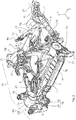
- Fig. 1 to 3 Based on Fig. 1 to 3 is described below, the geometry of one of the unit supports 21: Thus, in the Fig. 2 shown aggregate support 21 a total of four support arms 23, 25, 27, 29, which converge the same material and in one piece on a pedestal Anschraubbasis 31.
- the Anschraubbasis 31 of the respective unit support 21 is connected to the associated assembly bearing 19 in a screw S3 ( Fig. 1 ).
- Fig. 2 protrude the support arms 23 to 29 via a Hebelarmin I from the support base 31 and have at their free end in each case a flange portion 33 (FIG. Fig. 1 or 3 ) on.
- the support arms 23 to 29 are by means two screw joints S1 and screwed by means of two screw joints S2 with the drive unit 3.
- the screw joints S1 and S2 are aligned in different spatial directions to each other, as will be described later.
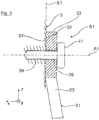
- the screw joint S1 between the drive unit 3 and the support arm 23 of the unit support 21 is shown in an enlarged partial sectional view. Accordingly, at the erignantsstelle S1 of the flange portion 33 of the support arm 23 and a terminal contour of the drive unit 3 on flat surfaces 35, 37 in abutment with each other.
- the flat surfaces 35, 37 are in the Fig. 3 in a connection plane E1.
- the two planar surfaces 35, 37 are penetrated by screw holes 39 through which a screw bolt 41 is guided, by means of which the unit support 21 is screwed to the drive unit 3 along a screw axis A1.
- the screw axis A1 of the screw joint S1 is in the Fig. 2 and 3 aligned in alignment with the vehicle longitudinal direction x.
- the support arms 23 to 29 of the respective unit support 21 clamp in the Fig. 2 a (indicated by a clip) inside corner region 43 having a corresponding outer corner 45 of the drive unit 3 (in the Fig. 2 dash-dotted lines indicated).
- the bolts 41 of the two support arms 23, 25 in the Fig. 2 Screwed along the first in the vehicle longitudinal direction x aligned screw axes A1 to the drive unit 3, namely to form the first screw joints S1.
- the support arms 27, 29 screwed to the second screw connection points S2 on the drive unit 3, by means of two bolts 41 along second screw axles A2 are aligned, which lie in alignment with the vehicle transverse direction y.
- the first and second screw axes A1, A2 are thus aligned orthogonal to each other.
- the connecting planes E1, E2 of the differently oriented screw connection points S1, S2 are aligned at right angles to each other.
- the assembly bearings 19 are constructed, for example, from radially outer bearing eyes 47, which are integrally formed on the respective cast nodes 5, 11. Radially within the bearing eyes 47 of the bearing core is arranged with an interposed elastomeric body.
- the bearing core is at the RYorganizsstelle S3 by means of a screw, not shown, along the screw axis A3 ( Fig. 1 ) screwed to the Anschraubbasis 31 of the unit support 21.
- the screw axis S3 in the figures is aligned between the screw-on base 31 and the respective front assembly bearing 19 in alignment with the vehicle transverse direction y.
- the two rear aggregate bearings 19 are aligned with their screw axes A3 in alignment with the vehicle longitudinal direction y.
Landscapes
- Engineering & Computer Science (AREA)
- Chemical & Material Sciences (AREA)
- Combustion & Propulsion (AREA)
- Transportation (AREA)
- Mechanical Engineering (AREA)
- Arrangement Or Mounting Of Propulsion Units For Vehicles (AREA)
- Body Structure For Vehicles (AREA)
Abstract
Description
- Die Erfindung betrifft eine Aggregatelagerung für ein Antriebsaggregat in einem Fahrzeug nach dem Oberbegriff des Patentanspruches 1.
- Das Antriebsaggregat eines Fahrzeugs, zum Beispiel eine Brennkraftmaschine mit Getriebe oder eine Elektromaschine, ist üblicherweise im Motorraum eines Fahrzeug-Vorderwagens angeordnet und über schwingungsdämpfende Aggregatelager an einer Tragstruktur des Fahrzeugaufbaus gelagert. Die Verbindung zwischen dem Antriebsaggregat und der Fahrzeugaufbau-Tragstruktur wird über Aggregatestützen, das heißt Motor- und/oder Getriebestützen, hergestellt, die über die Aggregatelager an der Tragstruktur des Fahrzeugaufbaus abgestützt sind. Beispielhaft kann das Antriebsaggregat in einer Drei- oder Vierpunktlagerung über vordere und hintere Aggregatelager an einem Hilfsrahmen im Vorderwagenbereich abgestützt sein.
- Aus der
DE 10 2005 039 312 B3 ist eine gattungsgemäße Aggregatelagerung bekannt, bei der ein aufbauseitiges Aggregatelager über eine Aggregatestütze das Antriebsaggregat trägt. Die Aggregatestütze weist drei Tragarme auf, die mittels einer Schraubverbindung am Antriebsaggregat verschraubt sind. Die drei Tragarme laufen an einer sockelförmigen Anschraubbasis zusammen, die mit dem Lagerkern eines schwingungsdämpfenden Aggregatelagers verschraubt ist. An jeder der Schraubverbindungsstellen sind das Antriebsaggregat und der jeweilige Tragarm über Planflächen in Anlageverbindung. Die Planflächen sind von Schraublöchern durchsetzt, durch die jeweils ein Schraubbolzen geführt ist, mittels dem der Aggregatestützen-Tragarm mit dem Antriebsaggregat entlang einer Schraubachse (das heißt einer Mittellängsachse des Schraubbolzens) verschraubt ist. Um während des Fahrbetriebs eine wirksame Schwingungstilgung im Aggregatelager zu erzielen, ist eine weitgehend schwingungssteife Anbindung des Antriebsaggregates am Aggregatelager erforderlich. Daher ist die Aggregatestütze mit ihren, sich über große Hebelarmlängen erstreckenden Tragarmen ausreichend materialintensiv auszuführen. - Aus der
DE 10 2012 0123 27 A1 ist eine Anordnung einer Elektromotoreneinheit in einem Fahrzeug bekannt. Die Elektromotoreinheit ist über zumindest zwei Aggregateträger an der Karosserie und an einem Achsträger befestigt. Die achsträgerseitigen befestigten Aggregatelager sind über Motorstützen am Aggregat (das heißt der Elektromotoreinheit) angebunden. Die Aggregatelager wirken nach Art einer Pendelstütze. Eines der Aggregatelager ist am Motordeckel/Gehäuse der Elektromotoreinheit befestigt, während das andere Aggregatelager an einem Getriebegehäuse befestigt ist. - Die Aufgabe der Erfindung besteht darin, eine Aggregatelagerung für ein Antriebsaggregat in einem Fahrzeug bereitzustellen, bei dem im Vergleich zum obigen Stand der Technik in einfacher Weise sowie insbesondere materialsparend eine schwingungssteife Anbindung des Antriebsaggregates am fahrzeugaufbauseitigen Aggregatelager ermöglicht ist.
- Die Erfindung beruht auf dem Sachverhalt, dass im obigen gattungsgemäßen Stand der Technik die Schraubachsen der drei Schraubverbindungsstellen zwischen der Aggregatestütze und dem Antriebsaggregat achsparallel ausgerichtet sind. Eine solche achsparallele Ausrichtung der Schraubachsen kann jedoch nur in eingeschränktem Umfang eine schwingungssteife Antriebsaggregat-Anbindung unterstützen. Vor diesem Hintergrund sind gemäß dem kennzeichnenden Teil des Patentanspruches 1 nicht mehr sämtliche Schraubachsen zwischen der Aggregatestütze und dem Antriebsaggregat achsparallel ausgerichtet, sondern sind zumindest zwei, in unterschiedlichen Raumrichtungen orientierte Schraubverbindungsstellen zwischen der Aggregatestütze und dem Antriebsaggregat bereitgestellt. Die Schraubbolzen der Schraubverbindungsstellen sind entlang erster und zweiter Schraubachsen angeordnet, die zueinander unterschiedlich räumlich ausgerichtet sind. Die ersten und zweiten Schraubachsen der verschraubten Schraubbolzen sind um einen Achswinkel zumindest zueinander schräggestellt, insbesondere zueinander rechtwinklig angeordnet.
- Die Erfindung ist im Hinblick auf eine einfachere Lesbarkeit mit Bezug auf ein konkretes bevorzugtes Ausführungsbeispiel beschrieben, bei dem die Aggregatestütze in Schraubverbindung mit dem Antriebsaggregat ist. Es versteht sich jedoch, dass die Erfindung nicht auf diese spezielle Befestigungsart beschränkt ist, sondern vielmehr sämtliche anderen Befestigungsarten mitumfassen soll.
- In einer technischen Ausführung kann in der ersten Schraubverbindungsstelle die erste Schraubachse des ersten Schraubbolzens in Flucht mit der Fahrzeuglängsrichtung ausgerichtet sein. In der zweiten Schraubverbindungsstelle kann dagegen die zweite Schraubachse des zweiten Fügeelementes in Flucht mit der Fahrzeugquerrichtung ausgerichtet sein.
- In einer technischen Umsetzung kann die Aggregatestütze insgesamt an vier Schraubverbindungsstellen am Antriebsaggregat verschraubt sein. In diesem Fall können im Hinblick auf eine besonders verwindungssteife Anbindung in zwei Schraubverbindungsstellen die Schraubbolzen entlang erster Schraubachsen ausgerichtet sein, während in den beiden anderen Schraubverbindungsstellen die Schraubbolzen entlang der zweiter Schraubachsen ausgerichtet sind.
- Im Hinblick auf eine betriebssichere, verwindungssteife Anbindung können in jeder Fügestelle das Antriebsaggregat und die Aggregatestütze über Planflächen zueinander in flächiger Anlagenverbindung sein. Die Planflächen liegen in einer Anbindungsebene, die orthogonal zum Schraubbolzen der jeweiligen Schraubverbindungsstelle angeordnet ist. Bevorzugt sind die Anbindungsebene der ersten Schraubverbindungsstelle und die Anbindungsebene der zweiten Schraubverbindungsstelle zueinander schräggestellt, insbesondere zueinander rechtwinklig angeordnet.
- Die Aggregatestütze kann in an sich gängiger Praxis zumindest einen ersten Tragarm und einen zweiten Tragarm aufweisen. Diese laufen an einer lagerseitigen sockelförmigen Anschraubbasis materialeinheitlich und einstückig zusammen, die an das fahrzeugaufbauseitige Aggregatelager anbindbar ist. Das fahrzeugaufbauseitige Aggregatelager kann exemplarisch ein aufbauseitiges Lagerauge aufweisen, in dem ein Lagerkern sowie ein zwischengeschalteter Elastomerkörper angeordnet ist. Der Lagerkern kann mit einer Anschraubbasis der Aggregatestütze verschraubt sein.
- Der obige erste Aggregatestützen-Tragarm kann über die erste Schraubverbindungsstelle am Antriebsaggregat angeschraubt sein, während der zweite Aggregatestützen-Tragarm über die zweite Schraubverbindungsstelle am Antriebsaggregat verschraubt ist.
- Besonders bevorzugt für eine verwindungssteife Anbindung ist es, wenn der erste Tragarm und der zweite Tragarm der Aggregatestütze einen Inneneckbereich aufspannen, der in der Zusammenbaulage eine Außenecke des Antriebsaggregates einfasst.
- Wie oben erwähnt, ist die Anschraubbasis der Aggregatestütze in Schraubverbindung mit dem fahrzeugaufbauseitigen Aggregatelager. Hierzu kann die Anschraubbasis der Aggregatestütze mittels eines Schraubbolzens entlang einer Schraubachse A3 mit dem Aggregatelager (zum Beispiel dessen Lagerkern) verschraubt sein. Im Hinblick auf einen verwindungssteifen Verbund zwischen dem Antriebsaggregat und dem Fahrzeugaufbau ist es bevorzugt, wenn die Schraubachse A3 zwischen der Anschraubbasis der Aggregatestütze und dem Aggregatelager in Flucht ausgerichtet ist mit der ersten Schraubachse A1 oder der zweiten Schraubachse A2 zwischen dem Antriebsaggregat und der Aggregatestütze.
- Die vorstehend erläuterten und/oder in den Unteransprüchen wiedergegebenen vorteilhaften Aus- und/oder Weiterbildungen der Erfindung können - außer zum Beispiel in den Fällen eindeutiger Abhängigkeiten oder unvereinbarer Alternativen - einzeln oder aber auch in beliebiger Kombination miteinander zur Anwendung kommen.
- Die Erfindung und ihre vorteilhaften Aus- und Weiterbildungen sowie deren Vorteile werden nachfolgend anhand von Zeichnungen näher erläutert.
- Es zeigen:
- Fig. 1
- in einer perspektivischen Darstellung einen Hilfsrahmen für einen Vorderwagen-Bereich eines Kraftfahrzeugs;
- Fig. 2
- in einer vergrößerten perspektivischen Teilansicht eine Aggregatestütze zur verwindungssteifen Anbindung eines Antriebsaggregats am Hilfsrahmen; und
- Fig. 3
- in einer Schnittdarstellung eine Schraubverbindungsstelle S1 zwischen dem Antriebsaggregat und einem Tragarm der Aggregatestütze.
- In der
Fig. 1 ist in Alleinstellung ein Hilfsrahmen 1 gezeigt, auf dem ein hier nicht dargestelltes Antriebsaggregat 3 (Fig. 2 oder3 ) abstützbar ist. Der Hilfsrahmen 1 weist in derFig. 1 zwei vordere seitliche Gussknoten 5 auf, die über einen Hilfsrahmen-Querträger 7 miteinander verbunden sind. Die beiden vorderen Gussknoten 5 sind über seitliche Hilfsrahmen-Längsträger 9 in der Fahrzeuglängsrichtung x nach hinten verlängert, die an hinteren Gussknoten 11 mit einem hinteren Hilfsrahmen-Querträger 13 zusammenlaufen. Die beiden vorderen Gussknoten 5 des Hilfsrahmens 1 sind in der Zusammenbaulage an Schraubpunkten 15 mit nur strichpunktiert angedeuteten Karosserie-Längsträgern 17 befestigt. Wie aus derFig. 1 weiter hervorgeht, sind an jedem der Gussknoten 5, 11 Aggregatelager 19 vorgesehen, die jeweils mit Aggregatestützen 21 verschraubt sind, wodurch sich das Antriebsaggregat 3, vorzugsweise eine Elektromaschine, unter Bildung einer Vierpunktlagerung auf dem Hilfsrahmen 1 abstützt. - Anhand der
Fig. 1 bis 3 ist nachfolgend die Geometrie einer der Aggregatestützen 21 beschrieben: So weist die in derFig. 2 gezeigte Aggregatestütze 21 insgesamt vier Tragarme 23, 25, 27, 29 auf, die materialeinheitlich und einstückig an einer sockelförmigen Anschraubbasis 31 zusammenlaufen. Die Anschraubbasis 31 der jeweiligen Aggregatestütze 21 ist mit den zugeordneten Aggregatelager 19 in einer Schraubverbindung S3 (Fig. 1 ). - Gemäß der
Fig. 2 ragen die Tragarme 23 bis 29 über eine Hebelarmlänge I von der Abstützbasis 31 ab und weisen an ihrem freien Ende jeweils einen Flanschabschnitt 33 (Fig. 1 oder3 ) auf. Die Tragarme 23 bis 29 sind mittels zweier Schraubverbindungsstellen S1 und mittels zweier Schraubverbindungsstellen S2 mit dem Antriebsaggregat 3 verschraubt. Die Schraubverbindungsstellen S1 und S2 sind in unterschiedlichen Raumrichtungen zueinander ausgerichtet, wie es später noch beschrieben wird. - In der
Fig. 3 ist die Schraubverbindungsstelle S1 zwischen dem Antriebsaggregat 3 und dem Tragarm 23 der Aggregatestütze 21 in einer vergrößerten Teilschnittansicht gezeigt. Demzufolge sind an der Schraubverbindungsstelle S1 der Flanschabschnitt 33 des Tragarms 23 und eine Anschlußkontur des Antriebsaggregats 3 an Planflächen 35, 37 miteinander in Anlageverbindung. Die Planflächen 35, 37 liegen in derFig. 3 in einer Anbindungsebene E1. Zudem sind die beiden Planflächen 35, 37 mit Schraublöchern 39 durchsetzt, durch die ein Schraubbolzen 41 geführt ist, mittels dem die Aggregatestütze 21 mit dem Antriebsaggregat 3 entlang einer Schraubachse A1 verschraubt ist. Die Schraubachse A1 der Schraubverbindungsstelle S1 ist in derFig. 2 und3 in Flucht zur Fahrzeuglängsrichtung x ausgerichtet. - Die Tragarme 23 bis 29 der jeweiligen Aggregatestütze 21 spannen in der
Fig. 2 einen (mittels einer Klammer hervorgehobenen) Inneneckbereich 43 auf, der eine korrespondierende Außenecke 45 des Antriebsaggregats 3 (in derFig. 2 strichpunktiert angedeutet) einfasst. Hierfür sind die Schraubbolzen 41 der beiden Tragarme 23, 25 in derFig. 2 entlang der ersten in der Fahrzeuglängsrichtung x ausgerichteten Schraubachsen A1 mit dem Antriebsaggregat 3 verschraubt, und zwar unter Bildung der ersten Schraubverbindungsstellen S1. Im Gegensatz dazu sind die Tragarme 27, 29 an den zweiten Schraubverbindungstellen S2 am Antriebsaggregat 3 verschraubt, und zwar mittels zweier Schraubbolzen 41, die entlang von zweiten Schraubachsen A2 ausgerichtet sind, die in Flucht zur Fahrzeugquerrichtung y liegen. - Die ersten und zweiten Schraubachsen A1, A2 sind somit zueinander orthogonal ausgerichtet. In gleicher Weise sind auch die Anbindungsebenen E1, E2 der unterschiedlich orientierten Schraubverbindungsstellen S1, S2 zueinander rechtwinklig ausgerichtet.
- Aufgrund dieser speziellen Anbindungsgeometrie der Tragarme 23 bis 29 der jeweiligen Aggregatestütze 21 am Antriebsaggregat 3 ergibt sich ein besonders verwindungssteifer Verbund zwischen dem Antriebsaggregat 3 und der jeweiligen Aggregatestütze 21, wodurch die Aggregatestütze 21 im Vergleich zu bekannten Aggregatestützen weniger materialintensiv ausführbar ist, ohne dass deren Schwingungssteifigkeit beeinträchtigt ist.
- In den Figuren sind die Aggregatelager 19 beispielhaft aus radial äußeren Lageraugen 47 aufgebaut, die an den jeweiligen Gussknoten 5, 11 angeformt sind. Radial innerhalb der Lageraugen 47 ist der Lagerkern mit zwischengeschaltetem Elastomerkörper angeordnet. Der Lagerkern ist an der Schraubverbindungsstelle S3 mittels eines nicht gezeigten Schraubbolzens entlang der Schraubachse A3 (
Fig. 1 ) mit der Anschraubbasis 31 der Aggregatestütze 21 verschraubt. Im Hinblick auf eine weitere Steigerung der Schwingungssteifigkeit ist in den Figuren die Schraubachse S3 zwischen der Anschraubbasis 31 und dem jeweiligen vorderen Aggregatelager 19 in Flucht mit der Fahrzeugquerrichtung y ausgerichtet. Im Unterschied dazu sind die beiden hinteren Aggregatelager 19 mit ihren Schraubachsen A3 in Flucht zur Fahrzeuglängsrichtung y ausgerichtet.
Claims (9)
- Aggregatelagerung für ein Antriebsaggregat (3) in einem Fahrzeug, mit zumindest einem am Fahrzeugaufbau (1) angeordneten Aggregatelager (19), das über zumindest eine Aggregatestütze (21) das Antriebsaggregat (3) trägt, wobei die Aggregatestütze (21) über zumindest eine erste Fügestelle, insbesondere Schraubverbindungsstelle (S1), und eine zweite Fügestelle, insbesondere Schraubverbindungsstelle (S2), am Antriebsaggregat (3) angebunden ist, wobei in der ersten Fügestelle (S1) die Aggregatestütze (21) mittels eines ersten Fügeelements, insbesondere Schraubbolzen (41), entlang einer ersten Fügeachse, insbesondere Schraubachse (A1), mit dem Antriebsaggregat (3) zusammengefügt, insbesondere verschraubt ist, dadurch gekennzeichnet, dass in der zweiten Fügestelle (S2) die Aggregatestütze (21) mittels eines zweiten Fügeelements, insbesondere Schraubbolzen (41), entlang einer zweiten Fügeachse, insbesondere Schraubachse (A2), mit dem Antriebsaggregat (3) zusammengefügt, insbesondere verschraubt ist, und dass die erste Fügeachse (A1) und die zweite Fügeachse (A2) zueinander um einen Achswinkel (α) zumindest schräggestellt, insbesondere zueinander rechtwinklig angeordnet sind.
- Aggregatelagerung nach Anspruch 1, dadurch gekennzeichnet, dass in der ersten Fügestelle (S1) die erste Fügeachse (A1) des ersten Fügeelements (41) in Flucht zur Fahrzeuglängsrichtung (x) ausgerichtet ist, und dass in der zweiten Fügestelle (S2) die zweite Fügeachse (A2) des zweiten Fügeelements (41) in Flucht zur Fahrzeugquerrichtung (y) ausgerichtet ist.
- Aggregatelagerung nach Anspruch 1 oder 2, dadurch gekennzeichnet, dass die Aggregatestütze (21) insgesamt an vier Fügestellen (S1, S2) am Antriebsaggregat (3) angebunden ist, und dass in zwei Fügestellen (S1) die Fügeelemente (41) entlang der ersten Fügeachse (A1) ausgerichtet sind, und dass in den zwei anderen Fügestellen (S2) die Fügeelemente (41) entlang der zweiten Fügeachse (A2) ausgerichtet sind.
- Aggregatelagerung nach Anspruch 1, 2 oder 3, dadurch gekennzeichnet, dass an jeder Fügestelle (S1, S2) das Antriebsaggregat (3) und die Aggregatestütze (21) über Planflächen (35, 37) in Anlageverbindung sind, die in zumindest einer Anbindungsebene (E1, E2) liegen, die orthogonal zum Fügeelement (41) der jeweiligen Fügestelle (S1, S2) angeordnet ist.
- Aggregatelagerung nach Anspruch 4, dadurch gekennzeichnet, dass die Anbindungsebene (E1) der ersten Fügestelle (S1) und die Anbindungsebene (E2) der zweiten Fügestelle (S2) zueinander schräggestellt sind, insbesondere zueinander rechtwinklig angeordnet sind.
- Aggregatelagerung nach einem der vorhergehenden Ansprüche, dadurch gekennzeichnet, dass die Aggregatestütze (21) zumindest einen ersten Tragarm (23, 25) und zumindest einen zweiten Tragarm (27, 29) aufweist, die an einer lagerseitigen Anschraubbasis (31), die mit dem Aggregatelager (19) verschraubbar ist, und dass der erste Aggregatestützen-Tragarm (23, 25) über die erste Fügestelle (S1) am Antriebsaggregat (3) angebunden ist, und dass der zweite Aggregatestützen-Tragarm (27, 29) über die zweite Fügestelle (S2) am Antriebsaggregat (3) angebunden ist.
- Aggregatelagerung nach Anspruch 6, dadurch gekennzeichnet, dass die ersten und zweiten Tragarme (23, 25, 27, 29) der Aggregatestütze (21) einen Inneneckbereich (43) aufspannen, der eine Außenecke (45) des Antriebsaggregats (3) einfasst.
- Aggregatelagerung nach einem der vorhergehenden Ansprüche, dadurch gekennzeichnet, dass die Aggregatestütze (21) in einer Schraubverbindung (S3) mit dem Aggregatelager (19) ist, bei der die Aggregatestütze (21) mittels eines Schraubbolzens entlang einer Schraubachse (A3) mit dem Aggregatelager (19) verschraubt ist, und dass insbesondere die Schraubachse (A3) mit der ersten oder zweiten Fügeachse (A1, A2) in Flucht ausgerichtet ist.
- Aggregatelagerung nach einem der vorhergehenden Ansprüche, dadurch gekennzeichnet, dass das Aggregatelager (19) ein aufbauseitiges Lagerauge (47) aufweist, in dem ein Lagerkern mit zwischengeschaltetem Elastomerkörper angeordnet ist, und dass der Lagerkern mit der Aggregatestütze (21) verschraubt ist.
Applications Claiming Priority (1)
| Application Number | Priority Date | Filing Date | Title |
|---|---|---|---|
| DE102015016390.6A DE102015016390B4 (de) | 2015-12-17 | 2015-12-17 | Aggregatelagerung für ein Fahrzeug-Antriebsaggregat |
Publications (2)
| Publication Number | Publication Date |
|---|---|
| EP3181390A1 true EP3181390A1 (de) | 2017-06-21 |
| EP3181390B1 EP3181390B1 (de) | 2020-09-23 |
Family
ID=57394421
Family Applications (1)
| Application Number | Title | Priority Date | Filing Date |
|---|---|---|---|
| EP16200255.4A Active EP3181390B1 (de) | 2015-12-17 | 2016-11-23 | Fahrzeug mit einem antriebsaggregat und einer aggregatelagerung |
Country Status (4)
| Country | Link |
|---|---|
| US (1) | US10118476B2 (de) |
| EP (1) | EP3181390B1 (de) |
| CN (1) | CN107020939B (de) |
| DE (1) | DE102015016390B4 (de) |
Cited By (2)
| Publication number | Priority date | Publication date | Assignee | Title |
|---|---|---|---|---|
| WO2019091814A1 (de) * | 2017-11-10 | 2019-05-16 | Volkswagen Aktiengesellschaft | Hinterachshilfsrahmen mit einer lagerung für eine antriebseinheit |
| GB2587624A (en) * | 2019-10-01 | 2021-04-07 | Caterpillar Inc | Mounting system |
Families Citing this family (9)
| Publication number | Priority date | Publication date | Assignee | Title |
|---|---|---|---|---|
| DE102015004465B4 (de) * | 2015-04-04 | 2018-09-06 | Audi Ag | Zweispuriges Fahrzeug |
| DE102017206391B4 (de) | 2017-04-13 | 2022-11-03 | Audi Ag | Fahrzeug mit einer Aggregatelagerung |
| CA3068479A1 (en) * | 2017-07-28 | 2019-01-31 | Dana Heavy Vehicle Systems Group, Llc | Cradle assembly for an electric axle assembly |
| WO2020053625A1 (en) * | 2018-09-12 | 2020-03-19 | Arcelormittal | Engine cradle for a motor vehicle |
| DE102018220728B4 (de) | 2018-11-30 | 2020-06-10 | Audi Ag | Aggregatelagerung |
| CN110370911A (zh) * | 2019-07-30 | 2019-10-25 | 重庆金康赛力斯新能源汽车设计院有限公司 | 电机悬置支架、电机悬置支架安装结构及汽车 |
| DE102019124348A1 (de) * | 2019-09-11 | 2021-03-11 | Bayerische Motoren Werke Aktiengesellschaft | Lagerungsanordnung einer Komponente an einem Achsträger für einen Kraftwagen sowie Kraftwagen, insbesondere Personenkraftwagen |
| DE102021214942A1 (de) * | 2021-12-22 | 2023-06-22 | Volkswagen Aktiengesellschaft | Hilfsrahmen für ein Kraftfahrzeug, Aggregatlagersystem und Fahrzeug |
| DE102023111872A1 (de) * | 2023-05-08 | 2024-11-14 | Audi Aktiengesellschaft | Karosseriestruktur für ein zweispuriges Fahrzeug |
Citations (6)
| Publication number | Priority date | Publication date | Assignee | Title |
|---|---|---|---|---|
| EP1361099A2 (de) * | 2002-05-10 | 2003-11-12 | Nissan Motor Company, Limited | Antriebsstranglagerung |
| US6708793B2 (en) * | 2001-05-11 | 2004-03-23 | General Motors Corporation | Double-isolated, symmetric, high-damped mount system |
| DE102005039312B3 (de) | 2005-08-19 | 2007-01-11 | Audi Ag | Vorrichtung zum Befestigen eines Aggregatlagers |
| DE102006041094A1 (de) * | 2006-09-01 | 2008-03-27 | Audi Ag | Lagervorrichtung zur Lagerung einer Fahrzeugkomponente an einer Karosserie eines Fahrzeugs |
| FR2980742A3 (fr) * | 2011-10-03 | 2013-04-05 | Renault Sas | Support de bloc-moteur |
| DE102012012327A1 (de) | 2012-06-20 | 2013-12-24 | Volkswagen Aktiengesellschaft | Anordnung einer Elektromotoreinheit im Motorraum eines Kraftfahrzeuges |
Family Cites Families (12)
| Publication number | Priority date | Publication date | Assignee | Title |
|---|---|---|---|---|
| DE19913230C2 (de) | 1999-03-23 | 2001-06-21 | Vti Ventil Technik Gmbh | Ventilarmatur für einen Druckbehälter |
| US6223850B1 (en) * | 2000-04-03 | 2001-05-01 | General Motors Corporation | Four point powertrain mounting and transmission inspection cover therefor |
| JP3472570B2 (ja) * | 2001-08-31 | 2003-12-02 | 本田技研工業株式会社 | エンジンの補機取付構造 |
| US8042793B2 (en) * | 2006-09-06 | 2011-10-25 | Honda Motor Co., Ltd. | Solid engine mount |
| US9428040B2 (en) * | 2012-12-21 | 2016-08-30 | Honda Motor Co., Ltd. | Electric motor mounting structure |
| DE102013007460A1 (de) | 2013-04-30 | 2014-10-30 | Audi Ag | Aggregatelageranordnung für Kraftfahrzeuge |
| JP6160704B2 (ja) * | 2013-10-24 | 2017-07-19 | トヨタ自動車株式会社 | エンジンマウント部を備える車両 |
| CN203752872U (zh) * | 2014-01-22 | 2014-08-06 | 东风商用车有限公司 | 一种四点布置式动力总成悬置装置 |
| GB2524990A (en) * | 2014-04-08 | 2015-10-14 | Bentley Motors Ltd | Mounting structure for an engine mount and method |
| CN204309579U (zh) * | 2014-12-18 | 2015-05-06 | 安徽瑞泰汽车零部件有限责任公司 | 一种汽车发动机固定安装支架 |
| CN204472533U (zh) * | 2014-12-30 | 2015-07-15 | 常林股份有限公司 | 大吨位装载机发动机的支撑结构 |
| US9630484B1 (en) * | 2016-03-28 | 2017-04-25 | Nissan North America, Inc. | Vehicle engine mount structure |
-
2015
- 2015-12-17 DE DE102015016390.6A patent/DE102015016390B4/de not_active Expired - Fee Related
-
2016
- 2016-11-23 EP EP16200255.4A patent/EP3181390B1/de active Active
- 2016-12-07 US US15/371,981 patent/US10118476B2/en active Active
- 2016-12-15 CN CN201611159987.7A patent/CN107020939B/zh active Active
Patent Citations (6)
| Publication number | Priority date | Publication date | Assignee | Title |
|---|---|---|---|---|
| US6708793B2 (en) * | 2001-05-11 | 2004-03-23 | General Motors Corporation | Double-isolated, symmetric, high-damped mount system |
| EP1361099A2 (de) * | 2002-05-10 | 2003-11-12 | Nissan Motor Company, Limited | Antriebsstranglagerung |
| DE102005039312B3 (de) | 2005-08-19 | 2007-01-11 | Audi Ag | Vorrichtung zum Befestigen eines Aggregatlagers |
| DE102006041094A1 (de) * | 2006-09-01 | 2008-03-27 | Audi Ag | Lagervorrichtung zur Lagerung einer Fahrzeugkomponente an einer Karosserie eines Fahrzeugs |
| FR2980742A3 (fr) * | 2011-10-03 | 2013-04-05 | Renault Sas | Support de bloc-moteur |
| DE102012012327A1 (de) | 2012-06-20 | 2013-12-24 | Volkswagen Aktiengesellschaft | Anordnung einer Elektromotoreinheit im Motorraum eines Kraftfahrzeuges |
Cited By (4)
| Publication number | Priority date | Publication date | Assignee | Title |
|---|---|---|---|---|
| WO2019091814A1 (de) * | 2017-11-10 | 2019-05-16 | Volkswagen Aktiengesellschaft | Hinterachshilfsrahmen mit einer lagerung für eine antriebseinheit |
| CN111278717A (zh) * | 2017-11-10 | 2020-06-12 | 大众汽车有限公司 | 带有用于驱动单元的支承的后桥副车架 |
| US11673607B2 (en) | 2017-11-10 | 2023-06-13 | Volkswagen Aktiengesellschaft | Rear axle supporting frame comprising a mounting device for a drive unit |
| GB2587624A (en) * | 2019-10-01 | 2021-04-07 | Caterpillar Inc | Mounting system |
Also Published As
| Publication number | Publication date |
|---|---|
| DE102015016390B4 (de) | 2017-10-12 |
| CN107020939A (zh) | 2017-08-08 |
| CN107020939B (zh) | 2019-06-14 |
| US20170174065A1 (en) | 2017-06-22 |
| US10118476B2 (en) | 2018-11-06 |
| DE102015016390A1 (de) | 2017-06-22 |
| EP3181390B1 (de) | 2020-09-23 |
Similar Documents
| Publication | Publication Date | Title |
|---|---|---|
| DE102015016390B4 (de) | Aggregatelagerung für ein Fahrzeug-Antriebsaggregat | |
| DE102016000669B3 (de) | Karosseriestruktur für ein zweispuriges Fahrzeug | |
| DE102007044636B4 (de) | Fahrzeug mit einer Brennstoffzelleneinheit | |
| DE3128340C2 (de) | ||
| DE19628651A1 (de) | Elastische Halterung mit zwei axial zusammengedrückten Elementen | |
| DE102020104443B4 (de) | Fahrzeug-Antriebseinheit | |
| EP3142884A1 (de) | Aggregatlagerung | |
| DE102007035004A1 (de) | Radlenkvorrichtung | |
| DE112018006255T5 (de) | Armstützenkonstruktion | |
| EP2772378A1 (de) | Doppelrad-Antriebsmodul | |
| DE602004006325T2 (de) | Haltevorrichtung für einen Lüftermotor | |
| DE102017220203A1 (de) | Aggregatelagerung für ein Antriebsaggregat in einem Fahrzeug | |
| EP4549191A2 (de) | Anordnung zur antriebslagerung | |
| DE102016218302A1 (de) | Lagereinrichtung für eine Blattfederanordnung einer Radaufhängung | |
| AT505344B1 (de) | Lagerung eines vorderachsgetriebes bei einem kraftfahrzeug | |
| DE102007002676A1 (de) | Fahrzeugrahmenanordnung mit diagonalen Abstandshaltern | |
| DE102011079617A1 (de) | Schraubverbindung | |
| DE102018118340B4 (de) | Nutzfahrzeugachsaufhängung | |
| DE60001863T2 (de) | Vorrichtung zur Aufhängung einer Antriebseinheit am Kraftfahrzeugaufbau | |
| DE102008026705B4 (de) | Motorrad mit einer Hinterradlagerung und einer Dämpfungseinrichtung zur Dämpfung von Pendelschwingungen | |
| DE102010053691A1 (de) | Elastisches Kupplungselement zur Verbindung von zwei Antriebswellen | |
| EP3873791B1 (de) | Fahrzeug mit einer tragstruktur | |
| DE102019200769A1 (de) | Getriebegehäuse und Anordnung zur Abstützung eines Getriebes | |
| DE102013103691B4 (de) | Elastisches Lager | |
| DE102016225470B4 (de) | Aggregatlager zum Abstützen einer Antriebskomponente eines Kraftfahrzeuges |
Legal Events
| Date | Code | Title | Description |
|---|---|---|---|
| PUAI | Public reference made under article 153(3) epc to a published international application that has entered the european phase |
Free format text: ORIGINAL CODE: 0009012 |
|
| STAA | Information on the status of an ep patent application or granted ep patent |
Free format text: STATUS: THE APPLICATION HAS BEEN PUBLISHED |
|
| AK | Designated contracting states |
Kind code of ref document: A1 Designated state(s): AL AT BE BG CH CY CZ DE DK EE ES FI FR GB GR HR HU IE IS IT LI LT LU LV MC MK MT NL NO PL PT RO RS SE SI SK SM TR |
|
| AX | Request for extension of the european patent |
Extension state: BA ME |
|
| STAA | Information on the status of an ep patent application or granted ep patent |
Free format text: STATUS: REQUEST FOR EXAMINATION WAS MADE |
|
| 17P | Request for examination filed |
Effective date: 20171221 |
|
| RBV | Designated contracting states (corrected) |
Designated state(s): AL AT BE BG CH CY CZ DE DK EE ES FI FR GB GR HR HU IE IS IT LI LT LU LV MC MK MT NL NO PL PT RO RS SE SI SK SM TR |
|
| STAA | Information on the status of an ep patent application or granted ep patent |
Free format text: STATUS: EXAMINATION IS IN PROGRESS |
|
| 17Q | First examination report despatched |
Effective date: 20190703 |
|
| GRAP | Despatch of communication of intention to grant a patent |
Free format text: ORIGINAL CODE: EPIDOSNIGR1 |
|
| STAA | Information on the status of an ep patent application or granted ep patent |
Free format text: STATUS: GRANT OF PATENT IS INTENDED |
|
| INTG | Intention to grant announced |
Effective date: 20200420 |
|
| GRAS | Grant fee paid |
Free format text: ORIGINAL CODE: EPIDOSNIGR3 |
|
| GRAA | (expected) grant |
Free format text: ORIGINAL CODE: 0009210 |
|
| STAA | Information on the status of an ep patent application or granted ep patent |
Free format text: STATUS: THE PATENT HAS BEEN GRANTED |
|
| AK | Designated contracting states |
Kind code of ref document: B1 Designated state(s): AL AT BE BG CH CY CZ DE DK EE ES FI FR GB GR HR HU IE IS IT LI LT LU LV MC MK MT NL NO PL PT RO RS SE SI SK SM TR |
|
| REG | Reference to a national code |
Ref country code: GB Ref legal event code: FG4D Free format text: NOT ENGLISH |
|
| REG | Reference to a national code |
Ref country code: CH Ref legal event code: EP |
|
| REG | Reference to a national code |
Ref country code: DE Ref legal event code: R096 Ref document number: 502016011235 Country of ref document: DE |
|
| REG | Reference to a national code |
Ref country code: IE Ref legal event code: FG4D Free format text: LANGUAGE OF EP DOCUMENT: GERMAN |
|
| REG | Reference to a national code |
Ref country code: AT Ref legal event code: REF Ref document number: 1316048 Country of ref document: AT Kind code of ref document: T Effective date: 20201015 |
|
| PG25 | Lapsed in a contracting state [announced via postgrant information from national office to epo] |
Ref country code: GR Free format text: LAPSE BECAUSE OF FAILURE TO SUBMIT A TRANSLATION OF THE DESCRIPTION OR TO PAY THE FEE WITHIN THE PRESCRIBED TIME-LIMIT Effective date: 20201224 Ref country code: SE Free format text: LAPSE BECAUSE OF FAILURE TO SUBMIT A TRANSLATION OF THE DESCRIPTION OR TO PAY THE FEE WITHIN THE PRESCRIBED TIME-LIMIT Effective date: 20200923 Ref country code: HR Free format text: LAPSE BECAUSE OF FAILURE TO SUBMIT A TRANSLATION OF THE DESCRIPTION OR TO PAY THE FEE WITHIN THE PRESCRIBED TIME-LIMIT Effective date: 20200923 Ref country code: FI Free format text: LAPSE BECAUSE OF FAILURE TO SUBMIT A TRANSLATION OF THE DESCRIPTION OR TO PAY THE FEE WITHIN THE PRESCRIBED TIME-LIMIT Effective date: 20200923 Ref country code: BG Free format text: LAPSE BECAUSE OF FAILURE TO SUBMIT A TRANSLATION OF THE DESCRIPTION OR TO PAY THE FEE WITHIN THE PRESCRIBED TIME-LIMIT Effective date: 20201223 Ref country code: NO Free format text: LAPSE BECAUSE OF FAILURE TO SUBMIT A TRANSLATION OF THE DESCRIPTION OR TO PAY THE FEE WITHIN THE PRESCRIBED TIME-LIMIT Effective date: 20201223 |
|
| PG25 | Lapsed in a contracting state [announced via postgrant information from national office to epo] |
Ref country code: RS Free format text: LAPSE BECAUSE OF FAILURE TO SUBMIT A TRANSLATION OF THE DESCRIPTION OR TO PAY THE FEE WITHIN THE PRESCRIBED TIME-LIMIT Effective date: 20200923 Ref country code: LV Free format text: LAPSE BECAUSE OF FAILURE TO SUBMIT A TRANSLATION OF THE DESCRIPTION OR TO PAY THE FEE WITHIN THE PRESCRIBED TIME-LIMIT Effective date: 20200923 |
|
| REG | Reference to a national code |
Ref country code: NL Ref legal event code: MP Effective date: 20200923 |
|
| REG | Reference to a national code |
Ref country code: LT Ref legal event code: MG4D |
|
| PG25 | Lapsed in a contracting state [announced via postgrant information from national office to epo] |
Ref country code: EE Free format text: LAPSE BECAUSE OF FAILURE TO SUBMIT A TRANSLATION OF THE DESCRIPTION OR TO PAY THE FEE WITHIN THE PRESCRIBED TIME-LIMIT Effective date: 20200923 Ref country code: CZ Free format text: LAPSE BECAUSE OF FAILURE TO SUBMIT A TRANSLATION OF THE DESCRIPTION OR TO PAY THE FEE WITHIN THE PRESCRIBED TIME-LIMIT Effective date: 20200923 Ref country code: PT Free format text: LAPSE BECAUSE OF FAILURE TO SUBMIT A TRANSLATION OF THE DESCRIPTION OR TO PAY THE FEE WITHIN THE PRESCRIBED TIME-LIMIT Effective date: 20210125 Ref country code: SM Free format text: LAPSE BECAUSE OF FAILURE TO SUBMIT A TRANSLATION OF THE DESCRIPTION OR TO PAY THE FEE WITHIN THE PRESCRIBED TIME-LIMIT Effective date: 20200923 Ref country code: RO Free format text: LAPSE BECAUSE OF FAILURE TO SUBMIT A TRANSLATION OF THE DESCRIPTION OR TO PAY THE FEE WITHIN THE PRESCRIBED TIME-LIMIT Effective date: 20200923 Ref country code: LT Free format text: LAPSE BECAUSE OF FAILURE TO SUBMIT A TRANSLATION OF THE DESCRIPTION OR TO PAY THE FEE WITHIN THE PRESCRIBED TIME-LIMIT Effective date: 20200923 |
|
| PG25 | Lapsed in a contracting state [announced via postgrant information from national office to epo] |
Ref country code: PL Free format text: LAPSE BECAUSE OF FAILURE TO SUBMIT A TRANSLATION OF THE DESCRIPTION OR TO PAY THE FEE WITHIN THE PRESCRIBED TIME-LIMIT Effective date: 20200923 Ref country code: IS Free format text: LAPSE BECAUSE OF FAILURE TO SUBMIT A TRANSLATION OF THE DESCRIPTION OR TO PAY THE FEE WITHIN THE PRESCRIBED TIME-LIMIT Effective date: 20210123 Ref country code: AL Free format text: LAPSE BECAUSE OF FAILURE TO SUBMIT A TRANSLATION OF THE DESCRIPTION OR TO PAY THE FEE WITHIN THE PRESCRIBED TIME-LIMIT Effective date: 20200923 Ref country code: ES Free format text: LAPSE BECAUSE OF FAILURE TO SUBMIT A TRANSLATION OF THE DESCRIPTION OR TO PAY THE FEE WITHIN THE PRESCRIBED TIME-LIMIT Effective date: 20200923 |
|
| REG | Reference to a national code |
Ref country code: DE Ref legal event code: R097 Ref document number: 502016011235 Country of ref document: DE |
|
| PG25 | Lapsed in a contracting state [announced via postgrant information from national office to epo] |
Ref country code: SK Free format text: LAPSE BECAUSE OF FAILURE TO SUBMIT A TRANSLATION OF THE DESCRIPTION OR TO PAY THE FEE WITHIN THE PRESCRIBED TIME-LIMIT Effective date: 20200923 Ref country code: MC Free format text: LAPSE BECAUSE OF FAILURE TO SUBMIT A TRANSLATION OF THE DESCRIPTION OR TO PAY THE FEE WITHIN THE PRESCRIBED TIME-LIMIT Effective date: 20200923 |
|
| REG | Reference to a national code |
Ref country code: CH Ref legal event code: PL |
|
| PG25 | Lapsed in a contracting state [announced via postgrant information from national office to epo] |
Ref country code: LU Free format text: LAPSE BECAUSE OF NON-PAYMENT OF DUE FEES Effective date: 20201123 |
|
| PLBE | No opposition filed within time limit |
Free format text: ORIGINAL CODE: 0009261 |
|
| STAA | Information on the status of an ep patent application or granted ep patent |
Free format text: STATUS: NO OPPOSITION FILED WITHIN TIME LIMIT |
|
| REG | Reference to a national code |
Ref country code: BE Ref legal event code: MM Effective date: 20201130 |
|
| PG25 | Lapsed in a contracting state [announced via postgrant information from national office to epo] |
Ref country code: DK Free format text: LAPSE BECAUSE OF FAILURE TO SUBMIT A TRANSLATION OF THE DESCRIPTION OR TO PAY THE FEE WITHIN THE PRESCRIBED TIME-LIMIT Effective date: 20200923 Ref country code: CH Free format text: LAPSE BECAUSE OF NON-PAYMENT OF DUE FEES Effective date: 20201130 Ref country code: LI Free format text: LAPSE BECAUSE OF NON-PAYMENT OF DUE FEES Effective date: 20201130 Ref country code: SI Free format text: LAPSE BECAUSE OF FAILURE TO SUBMIT A TRANSLATION OF THE DESCRIPTION OR TO PAY THE FEE WITHIN THE PRESCRIBED TIME-LIMIT Effective date: 20200923 |
|
| 26N | No opposition filed |
Effective date: 20210624 |
|
| PG25 | Lapsed in a contracting state [announced via postgrant information from national office to epo] |
Ref country code: IT Free format text: LAPSE BECAUSE OF FAILURE TO SUBMIT A TRANSLATION OF THE DESCRIPTION OR TO PAY THE FEE WITHIN THE PRESCRIBED TIME-LIMIT Effective date: 20200923 Ref country code: IE Free format text: LAPSE BECAUSE OF NON-PAYMENT OF DUE FEES Effective date: 20201123 |
|
| PG25 | Lapsed in a contracting state [announced via postgrant information from national office to epo] |
Ref country code: TR Free format text: LAPSE BECAUSE OF FAILURE TO SUBMIT A TRANSLATION OF THE DESCRIPTION OR TO PAY THE FEE WITHIN THE PRESCRIBED TIME-LIMIT Effective date: 20200923 Ref country code: MT Free format text: LAPSE BECAUSE OF FAILURE TO SUBMIT A TRANSLATION OF THE DESCRIPTION OR TO PAY THE FEE WITHIN THE PRESCRIBED TIME-LIMIT Effective date: 20200923 Ref country code: CY Free format text: LAPSE BECAUSE OF FAILURE TO SUBMIT A TRANSLATION OF THE DESCRIPTION OR TO PAY THE FEE WITHIN THE PRESCRIBED TIME-LIMIT Effective date: 20200923 |
|
| PG25 | Lapsed in a contracting state [announced via postgrant information from national office to epo] |
Ref country code: MK Free format text: LAPSE BECAUSE OF FAILURE TO SUBMIT A TRANSLATION OF THE DESCRIPTION OR TO PAY THE FEE WITHIN THE PRESCRIBED TIME-LIMIT Effective date: 20200923 |
|
| PG25 | Lapsed in a contracting state [announced via postgrant information from national office to epo] |
Ref country code: BE Free format text: LAPSE BECAUSE OF NON-PAYMENT OF DUE FEES Effective date: 20201130 |
|
| REG | Reference to a national code |
Ref country code: AT Ref legal event code: MM01 Ref document number: 1316048 Country of ref document: AT Kind code of ref document: T Effective date: 20211123 |
|
| PG25 | Lapsed in a contracting state [announced via postgrant information from national office to epo] |
Ref country code: AT Free format text: LAPSE BECAUSE OF NON-PAYMENT OF DUE FEES Effective date: 20211123 |
|
| PG25 | Lapsed in a contracting state [announced via postgrant information from national office to epo] |
Ref country code: NL Free format text: LAPSE BECAUSE OF NON-PAYMENT OF DUE FEES Effective date: 20200923 |
|
| P01 | Opt-out of the competence of the unified patent court (upc) registered |
Effective date: 20230530 |
|
| PGFP | Annual fee paid to national office [announced via postgrant information from national office to epo] |
Ref country code: DE Payment date: 20251130 Year of fee payment: 10 |
|
| PGFP | Annual fee paid to national office [announced via postgrant information from national office to epo] |
Ref country code: GB Payment date: 20251120 Year of fee payment: 10 |
|
| PGFP | Annual fee paid to national office [announced via postgrant information from national office to epo] |
Ref country code: FR Payment date: 20251120 Year of fee payment: 10 |