EP3181216A1 - Labormischer und verfahren zum mischen eines mediums - Google Patents
Labormischer und verfahren zum mischen eines mediums Download PDFInfo
- Publication number
- EP3181216A1 EP3181216A1 EP16201114.2A EP16201114A EP3181216A1 EP 3181216 A1 EP3181216 A1 EP 3181216A1 EP 16201114 A EP16201114 A EP 16201114A EP 3181216 A1 EP3181216 A1 EP 3181216A1
- Authority
- EP
- European Patent Office
- Prior art keywords
- tool
- mixing
- rheology measurement
- rheology
- measurement
- Prior art date
- Legal status (The legal status is an assumption and is not a legal conclusion. Google has not performed a legal analysis and makes no representation as to the accuracy of the status listed.)
- Granted
Links
Images

Classifications
-
- G—PHYSICS
- G01—MEASURING; TESTING
- G01N—INVESTIGATING OR ANALYSING MATERIALS BY DETERMINING THEIR CHEMICAL OR PHYSICAL PROPERTIES
- G01N11/00—Investigating flow properties of materials, e.g. viscosity, plasticity; Analysing materials by determining flow properties
- G01N11/10—Investigating flow properties of materials, e.g. viscosity, plasticity; Analysing materials by determining flow properties by moving a body within the material
- G01N11/14—Investigating flow properties of materials, e.g. viscosity, plasticity; Analysing materials by determining flow properties by moving a body within the material by using rotary bodies, e.g. vane
-
- B—PERFORMING OPERATIONS; TRANSPORTING
- B01—PHYSICAL OR CHEMICAL PROCESSES OR APPARATUS IN GENERAL
- B01F—MIXING, e.g. DISSOLVING, EMULSIFYING OR DISPERSING
- B01F27/00—Mixers with rotary stirring devices in fixed receptacles; Kneaders
- B01F27/21—Mixers with rotary stirring devices in fixed receptacles; Kneaders characterised by their rotating shafts
- B01F27/213—Mixers with rotary stirring devices in fixed receptacles; Kneaders characterised by their rotating shafts characterised by the connection with the drive
-
- B—PERFORMING OPERATIONS; TRANSPORTING
- B01—PHYSICAL OR CHEMICAL PROCESSES OR APPARATUS IN GENERAL
- B01F—MIXING, e.g. DISSOLVING, EMULSIFYING OR DISPERSING
- B01F27/00—Mixers with rotary stirring devices in fixed receptacles; Kneaders
- B01F27/80—Mixers with rotary stirring devices in fixed receptacles; Kneaders with stirrers rotating about a substantially vertical axis
- B01F27/805—Mixers with rotary stirring devices in fixed receptacles; Kneaders with stirrers rotating about a substantially vertical axis wherein the stirrers or the receptacles are moved in order to bring them into operative position; Means for fixing the receptacle
- B01F27/806—Mixers with rotary stirring devices in fixed receptacles; Kneaders with stirrers rotating about a substantially vertical axis wherein the stirrers or the receptacles are moved in order to bring them into operative position; Means for fixing the receptacle with vertical displacement of the stirrer, e.g. in combination with means for pivoting the stirrer about a vertical axis in order to co-operate with different receptacles
-
- B—PERFORMING OPERATIONS; TRANSPORTING
- B01—PHYSICAL OR CHEMICAL PROCESSES OR APPARATUS IN GENERAL
- B01F—MIXING, e.g. DISSOLVING, EMULSIFYING OR DISPERSING
- B01F27/00—Mixers with rotary stirring devices in fixed receptacles; Kneaders
- B01F27/80—Mixers with rotary stirring devices in fixed receptacles; Kneaders with stirrers rotating about a substantially vertical axis
- B01F27/84—Mixers with rotary stirring devices in fixed receptacles; Kneaders with stirrers rotating about a substantially vertical axis with two or more stirrers rotating at different speeds or in opposite directions about the same axis
-
- B—PERFORMING OPERATIONS; TRANSPORTING
- B01—PHYSICAL OR CHEMICAL PROCESSES OR APPARATUS IN GENERAL
- B01F—MIXING, e.g. DISSOLVING, EMULSIFYING OR DISPERSING
- B01F35/00—Accessories for mixers; Auxiliary operations or auxiliary devices; Parts or details of general application
- B01F35/20—Measuring; Control or regulation
- B01F35/21—Measuring
- B01F35/2136—Viscosity
-
- B—PERFORMING OPERATIONS; TRANSPORTING
- B01—PHYSICAL OR CHEMICAL PROCESSES OR APPARATUS IN GENERAL
- B01F—MIXING, e.g. DISSOLVING, EMULSIFYING OR DISPERSING
- B01F35/00—Accessories for mixers; Auxiliary operations or auxiliary devices; Parts or details of general application
- B01F35/30—Driving arrangements; Transmissions; Couplings; Brakes
- B01F35/32—Driving arrangements
- B01F35/324—Driving independent stirrer shafts, i.e. not fitted on the container
-
- G—PHYSICS
- G01—MEASURING; TESTING
- G01N—INVESTIGATING OR ANALYSING MATERIALS BY DETERMINING THEIR CHEMICAL OR PHYSICAL PROPERTIES
- G01N11/00—Investigating flow properties of materials, e.g. viscosity, plasticity; Analysing materials by determining flow properties
- G01N2011/0046—In situ measurement during mixing process
Definitions
- the present invention relates to a laboratory mixer in which, during or shortly after completion of the mixing operation, the rheological properties of media can be detected in order to determine relevant characteristics therefrom.
- Predicting properties of mixed media is extremely important, especially in the concrete industry, as the range of concrete requirements has increased steadily in recent decades. Therefore, concretes are no longer manufactured as a three-phase material from cement, water and aggregates, but as a five-substance system, in addition to the three phases mentioned additives and additives are used.
- the composition of the concrete which can be found for the most diverse requirements, is very complex, and the experience of craftsmen alone is no longer sufficient.
- the invention includes a laboratory mixer in which optionally a mixing tool or a device for rheology measurement can be coupled to the drive. Both the mixing tool and the device for rheology measurement consist of an inner tool and an outer tool.
- the motor for driving the inner tool is preferably a torque motor (synchronous motor) with direct drive. It is therefore suitable both for the mixing process and for rheology measurement.
- This synchronous motor may, for example, have a rated speed of 500 rpm (revolutions per minute).
- the motor for driving the outer tool is preferably a motor with gear unit and engine brake.
- the vertical position of the drive unit and the container of the laboratory mixer are preferably mutually changeable by a further motor, so that the tools can either be driven into the mixing vessel or moved out of it.
- a combined mixed rheology measurement process is possible.
- rheology measurements in relative units are possible. Since the mixing tools are extremely easy to interchange with the tools for rheology measurement (with defined surfaces), the rheological properties can also be determined in absolute units (Pa / Pa ⁇ s). In this case, it can be avoided that significant segregation occurs after the mixing process, before a rheology measurement is carried out.
- one of the tools for rheology measurement is designed so that it can also be used for a mixing process or preventing segregation, which makes it possible that just before the rheology measurement, the mix is circulated again to measure the most accurate rheological value without any errors due to incipient segregation.
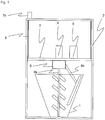
- the laboratory mixer has a mixing vessel 1, which is arranged within a frame construction 2.
- a cover plate 3 is provided, which is formed in the present embodiment as a plate with integrated in the frame structure 2 central spar.
- the torque motor (synchronous motor) 4 for driving a tool and another motor 5, comprising a gear unit with motor brake, arranged to drive the other tool.
- a coupling unit 6 is provided, with which a mixing tool 9, consisting of inner mixing tool 9a and outer mixing tool 9b, can be connected.
- the guide rails 8 are used for vertical guidance of the cover plate 3, which via a lifting motor 7a (not shown here) and a screw jack 7b is vertically movable up and down.
- the stroke motor 7 therefore, the position of the cover plate 3 with respect to the mixing container 1 can be changed, so that the mixing container 1 can be either open or closed by the cover plate 3.
- the mixing tools can be mounted or disconnected from the system.
- an inner mixing tool 9a and an outer mixing tool 9b are connected to the coupling unit 6.
- the inner mixing tool 9a is driven by the torque motor (synchronous motor) 4
- the outer mixing tool 9b is driven by the motor 5.
- a torque motor (synchronous motor) is a high-voltage, direct-drive electric drive from the group of low-speed machines.
- Fig. 2 shows an arrangement of the laboratory mixer, in which, however, not the mixing tool 9 is connected to the coupling unit 6, but a tool for rheology measurement 10, consisting of an inner tool for rheology measurement 10a and an outer tool for rheology measurement 10b.
- a cylindrical outer tool for rheology measurement 10b can be seen, which is configured in the present embodiment with mixing devices 11, so that it can also mix the mix in mixing vessel 1 with appropriate rotation or can prevent segregation of the previously mixed mixed.
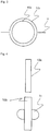
- Fig. 3 10 shows a cross-sectional view of the rheology measurement outer tool 10b with mixing devices 11, wherein an inner rheology measurement tool 10a is concentrically disposed within the rheology measurement outer tool 10b.
- the inner tool for rheology measurement 10a has at least one cylindrical segment, wherein the cylindrical segment has a smaller diameter than the outer tool for rheology measurement 10b.
- Both the rheology measurement outer tool 10b and the rheology measurement inner tool 10a have suitable attachment means with which they can be attached to the coupling unit 6.
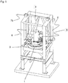
- Fig. 5 the cover plate 3 is above the mixing container 1, so it is a closed state of the laboratory mixer shown.
- the drive of the cover plate 3 is again illustrated by the guide rails and the lifting motor 7.
- the present embodiment represents a combination of mixer and rheometer.
- a torque motor (synchronous motor) 4 for driving the inner tool a highly accurate control is possible, so that even speeds that are only just above zero, can be driven. At the same time, the torque required for this can be very high.
- the advantage of such a torque motor (Snychronmotors) 4 is that no motor gear unit is necessary, which could cause by slip inaccuracies, especially in the rheology measurement. Transmission losses can thus be avoided.
- a speed-controlled operation of the engine can also rheological preferred torque-controlled operation done.
- the direct drive also enables very fast reversal of direction of rotation. The known from the rheology oscillating measurements are thus also possible in the laboratory mixer.
- the coupling unit 6 allows the inner mixing tool 9a and the outer mixing tool 9b to be rapidly exchanged for the inner rheology measurement tool 10a and the outer rheology measurement tool 10b, respectively.
- the cover plate 3 is movable, so can change their vertical position relative to the mixing container 1, a zero point measurement with the rheology tools (inner tool for rheology measurement 10a and external tool for rheology measurement 10b) is possible.
- the design of the laboratory mixer is not limited to the described embodiment.
- the shapes of the mixing tool 9 and the tool for rheology measurement 10 are shown here only by way of example.
- the inner tool for rheology measurement 10a may for example consist of several cylindrical segments with different diameters. Furthermore, a conical shape or truncated cone shape is possible. Furthermore, other rotationally symmetric shapes would be possible.
- a mixing process and a subsequent rheology measurement are carried out, for example, according to the following method.
- the laboratory mixer is equipped with the inner mixing tool 9a and the outer mixing tool 9b. Subsequently, the position of the cover plate 3 is changed so far down that the cover plate 3 covers the mixing container 1 and thus the inner Dip the mixing tool 9a and the outer mixing tool 9b in the medium to be mixed. Depending on the medium to be mixed, the inner mixing tool 9a and the outer mixing tool 9b are now rotated. If the user satisfies rheological measurements with relative units, the measurement is performed with the mixing tools (inner mixing tool 9a and outer mixing tool 9b).
- the cover plate 3 is moved upwards again after the mixing process, so that it no longer rests on the mixing container 1.
- the inner mixing tool 9a is replaced by the inner rheological measurement tool 10a
- the outer mixing tool 9b is replaced by the outer rheology measurement tool 10b.
- the inner tool for rheology measurement 10a is then rotated to determine the breakaway torque with a speed or torque ramp.
- the torque or speed is determined at the lowest resistance, ie in air.
- the cover plate 3 is moved further down until contact is made with the material over the bottom surface of the inner tool for rheology measurement 10a. Then a measurement takes place. The result of this measurement and the previously determined breakaway torque are taken into account in the evaluation of the completely submerged measuring body. Now the cover plate 3 is moved further down so that it rests on the mixing container 1. The cylindrical segment of the inner tool for rheology measurement 10a should completely submerge in the medium to be mixed. Subsequently, by the motor 5, the outer tool for rheology measurement 10b rotates.
- the rotation of the rheology measurement outer tool 10b is stopped, and the engine brake is activated in the engine 5.
- the inner tool for rheology measurement 10a is caused to rotate by the torque motor (synchronous motor) 4 starting from a very low rotational speed or a very low torque (determination of the yield stress). Thereafter, the speed or the torque is increased in several stages and determines the associated torques or speeds.
- oscillating measurements can be made with very fast changes of direction with increasing amplitude (deflection or torque).
- the cover plate 3 is moved back up so that the tools for rheology measurement 10a and 10b and the mixing container 1 can be cleaned.
- the outer tool for rheology measurement 10b is also rotated, but at a different speed than the inner tool for rheology measurement 10a. Even so, a determination of the rheological parameters is possible.
- this system is still possible to operate this system as a tribometer, whereby the pumpability of concrete is to be simulated.
- the measurement of tribological properties is only by high rotational speeds (preferably 10% -120% of the rated speed of the torque motor (synchronous motor) 4) possible. Therefore, much higher speeds must be selected, and an internal tribological measurement tool 10a 'can be provided with the material of the pump tubes. Slippage is therefore desirable here, since it also accrues in the pumping line.
- the present invention relates to a laboratory mixer in which both the mixing of the medium to be mixed and a measurement of the rheological properties of the medium to be mixed can be performed.
- a mixing tool 9 consisting of an inner mixing tool 9a and an outer mixing tool 9b
- a tool for rheology measurement 10 consisting of an inner tool for rheology measurement 10a and an outer tool for rheology measurement 10b
- the cover plate 3 of the mixing container 1 can be moved vertically.
- the inner tools 9a, 10a are driven by a torque motor (synchronous motor) 4.
- the outer tool for rheology measurement 10b also has mixing devices 11, so that the medium to be mixed can be circulated again immediately before the rheology measurement.
Landscapes
- Chemical & Material Sciences (AREA)
- Chemical Kinetics & Catalysis (AREA)
- General Health & Medical Sciences (AREA)
- Life Sciences & Earth Sciences (AREA)
- Analytical Chemistry (AREA)
- Biochemistry (AREA)
- Physics & Mathematics (AREA)
- General Physics & Mathematics (AREA)
- Immunology (AREA)
- Pathology (AREA)
- Health & Medical Sciences (AREA)
- Preparation Of Clay, And Manufacture Of Mixtures Containing Clay Or Cement (AREA)
- Mixers Of The Rotary Stirring Type (AREA)
Description
- Die vorliegende Erfindung bezieht sich auf einen Labormischer, bei welchem während oder kurz nach Abschluss des Mischvorgangs die rheologischen Eigenschaften von Medien erfasst werden können, um hieraus relevante Charakteristika zu bestimmen.
- Besonders in der Betonindustrie ist eine Vorhersage von Eigenschaften von vermischten Medien äußerst wichtig, da die Bandbreite der Anforderungen an Betone in den vergangenen Jahrzehnten stetig gestiegen ist. Daher werden Betone nicht mehr als Drei-Phasen-Werkstoff aus Zement, Wasser und Gesteinskörnungen, sondern als Fünf-Stoff-System gefertigt, wobei zusätzlich zu den drei genannten Phasen Zusatzstoffe und Zusatzmittel zum Einsatz kommen. Die für die unterschiedlichsten Anforderungen zu findende Zusammensetzung des Betons ist hierbei sehr komplex, und allein die Erfahrung von Handwerkern ist hierbei längst nicht mehr ausreichend.
- In der Praxis ist es daher wichtig, Mischungen herzustellen, hierbei eine ausreichende Durchmischung der verschiedenen Phasen zu erzielen, und dann die rheologischen Eigenschaften der Mischungen zu bestimmen.
- Eine Problematik kann hierbei auftreten, dass sich einzelne Phasen schnell wieder entmischen können. Außerdem kann es bei bestimmten Medien möglich sein, dass Mischungen ihre rheologischen Eigenschaften in Abhängigkeit von der Mischzeit ändern.
- Im Stand der Technik sind verschiedene Labormischer bekannt, beispielsweise ein Mörtelmischer Typ Hobart oder ein Intensivmischer Typ Eirich. Jedoch besteht hier das Problem, dass diese Mischer für die Mischaufgabe zwar geeignet sind, jedoch für eine rheologische Messung ein Transfer in ein gesondertes Rheometer erfolgen muss.
- Da in diesem Zeitraum Entmischung stattfinden kann, und durch die Umfüllung in ein anderes Gefäß zudem Änderungen der rheologischen Eigenschaften des Mischgutes auftreten können, können solche Vorgehensweisen keine zuverlässigen Aussagen über rheologische Eigenschaften liefern. Durch das Vorscheren der Probe und den eigentlichen Messvorgang im Rheometer sind Entmischungen unvermeidlich. Soll die Probe wiederholt vermessen werden, muss die Probe zuvor durch geeignete Maßnahmen wieder homogenisiert werden.
- Es ist daher die Aufgabe der vorliegenden Erfindung, einen Labormischer sowie ein Verfahren zur Verfügung zu stellen, bei dem bei der Vermischung der zu mischenden Medien die rheologischen Eigenschaften von homogenen Gemischen erfasst werden können, um hieraus Rückschlüsse auf relevante Eigenschaften der fertig gemischten Mischungen zu bestimmen.
- Diese Aufgabe wird durch einen Labormischer mit den Merkmalen gemäß Anspruch 1, sowie durch ein Verfahren gemäß Anspruch 8 sowie eine Verwendung gemäß der Ansprüche 13 und 15 gelöst. Weitere vorteilhafte Ausgestaltungen der Erfindung sind Gegenstand der abhängigen Ansprüche.
- Die Erfindung beinhaltet einen Labormischer, bei welchem an den Antrieb wahlweise ein Mischwerkzeug oder eine Vorrichtung zur Rheologiemessung gekoppelt werden kann. Sowohl das Mischwerkzeug als auch die Vorrichtung zur Rheologiemessung bestehen aus einem inneren Werkzeug und einem äußeren Werkzeug.
- Der Motor zum Antrieb des inneren Werkzeuges ist vorzugsweise ein Torquemotor (Synchronmotor) mit Direktantrieb. Er ist daher sowohl für den Mischvorgang als auch für die Rheologiemessung geeignet. Dieser Synchronmotor kann beispielsweise eine Nenndrehzahl von 500 UPM (Umdrehungen pro Minute) aufweisen.
- Der Motor zum Antrieb des äußeren Werkzeuges hingegen ist vorzugsweise ein Motor mit Getriebeeinheit und Motorbremse.
- Die vertikale Position der Antriebseinheit und des Behälters des Labormischers sind vorzugsweise durch einen weiteren Motor gegenseitig veränderbar, so dass die Werkzeuge entweder in das Mischgefäß hineingefahren oder aber aus diesem herausgefahren werden können.
- Durch die Verwendung des Labormischers ist ein kombinierter Misch-Rheologiemessungsvorgang möglich. Unter Verwendung der Mischwerkzeuge sind Rheologiemessungen in relativen Einheiten (Drehzahl/Drehmoment) möglich. Da die Mischwerkzeuge äußerst einfach mit den Werkzeugen zur Rheologiemessung (mit definierten Oberflächen) austauschbar sind, können die rheologischen Eigenschaften auch in absoluten Einheiten (Pa / Pa·s) ermittelt werden. Hierbei kann vermieden werden, dass signifikante Entmischung nach dem Mischvorgang eintritt, bevor eine Rheologiemessung durchgeführt wird. Weiterhin ist eines der Werkzeuge zur Rheologiemessung so ausgestaltet, dass es ebenfalls für einen Mischvorgang bzw. ein Verhindern der Entmischung herangezogen werden kann, womit es möglich wird, dass kurz vor der Rheologiemessung das Mischgut nochmals umgewälzt wird, um einen möglichst genauen rheologischen Wert messen zu können, ohne dass dabei eventuelle Fehler durch beginnende Entmischung eine Rolle spielen.
- Im Folgenden wird ein bevorzugtes Ausführungsbeispiel unter Bezugnahme auf die beigefügten Zeichnungen näher erläutert.
-
Fig. 1 zeigt eine Vorderansicht des Labormischers, wobei dieser hier in der Konfiguration zum Mischen dargestellt ist. -
Fig. 2 zeigt eine Vorderansicht des Labormischers, wobei dieser hier in einer Konfiguration zur Rheologiemessung dargestellt ist. -
Fig. 3 zeigt eine Querschnittansicht der Werkzeuge für die Rheologiemessung. -
Fig. 4 zeigt eine Explosionsansicht der Werkzeuge für die Rheologiemessung. -
Fig. 5 zeigt eine Gesamtansicht des Labormischers. - Wie in
Fig. 1 gezeigt, weist der Labormischer ein Mischgefäß 1 auf, welches innerhalb einer Rahmenkonstruktion 2 angeordnet ist. Zum Verschluss des Mischbehälters 1 ist eine Deckelplatte 3 vorgesehen, welche in der vorliegenden Ausführungsform als Platte mit in der Rahmenkonstruktion 2 integriertem Mittelholm ausgebildet ist. Auf dieser Deckelplatte 3 sind der Torquemotor (Synchronmotor) 4 zum Antrieb eines Werkzeugs und ein weiterer Motor 5, aufweisend eine Getriebeeinheit mit Motorbremse, zum Antrieb des anderen Werkzeugs angeordnet. Auf der unteren Seite der Deckelplatte 3 ist eine Kupplungseinheit 6 vorgesehen, mit welcher ein Mischwerkzeug 9, bestehend aus innerem Mischwerkzeug 9a und äußerem Mischwerkzeug 9b, verbunden werden kann. Die Führungsschienen 8 dienen der vertikalen Führung der Deckelplatte 3, welche über einen Hub-Motor 7a (hier nicht gezeigt) sowie ein Spindelhubgetriebe 7b nach oben und unten vertikal bewegbar ist. Durch den Hub-Motor 7 kann daher die Position der Deckelplatte 3 mit Bezug auf den Mischbehälter 1 verändert werden, so dass der Mischbehälter 1 wahlweise offen oder durch die Deckelplatte 3 verschlossen sein kann. Im offenen Zustand, wie inFig. 1 dargestellt, können die Mischwerkzeuge montiert oder vom System getrennt werden. - Im vorliegenden Fall ist ein inneres Mischwerkzeug 9a sowie ein äußeres Mischwerkzeug 9b mit der Kupplungseinheit 6 verbunden. Hierbei wird das innere Mischwerkzeug 9a vom Torquemotor (Synchronmotor) 4 angetrieben, wohingegen das äußere Mischwerkzeug 9b vom Motor 5 angetrieben wird. Ein Torquemotor (Synchronmotor) ist ein hochpoliger, elektrischer Direktantrieb aus der Gruppe der Langsamläufer.
-
Fig. 2 zeigt eine Anordnung des Labormischers, in welcher allerdings nicht das Mischwerkzeug 9 mit der Kupplungseinheit 6 verbunden ist, sondern ein Werkzeug zur Rheologiemessung 10, bestehend aus einem inneren Werkzeug zur Rheologiemessung 10a und einem äußeren Werkzeug zur Rheologiemessung 10b.
In dieser Abbildung ist ein zylinderförmiges äußeres Werkzeug zur Rheologiemessung 10b zu erkennen, welches in der vorliegenden Ausführungsform mit Mischvorrichtungen 11 ausgestaltet ist, so dass es bei entsprechender Rotation das Mischgut im Mischbehälter 1 ebenfalls durchmischen kann bzw. eine Entmischung des vorher durchmischten Mischguts verhindern kann. -
Fig. 3 zeigt eine Querschnittansicht des äußeren Werkzeugs zur Rheologiemessung 10b mit Mischvorrichtungen 11, wobei ein inneres Werkzeug zur Rheologiemessung 10a konzentrisch innerhalb des äußeren Werkzeugs zur Rheologiemessung 10b angeordnet ist. Durch diese Anordnung ist ein konstanter und über alle radialen Abschnitte gleicher Abstand zwischen innerem Werkzeug zur Rheologiemessung 10a und äußerem Werkzeugs zur Rheologiemessung 10b gegeben. - Wie in
Fig. 4 gezeigt, besitzt das innere Werkzeug zur Rheologiemessung 10a mindestens ein zylinderförmiges Segment, wobei das zylinderförmige Segment einen kleineren Druchmesser besitzt als das äußere Werkzeug zur Rheologiemessung 10b. Sowohl das äußere Werkzeug zur Rheologiemessung 10b als auch das innere Werkzeug zur Rheologiemessung 10a haben geeignete Befestigungsmittel, mit welchen sie an der Kupplungseinheit 6 befestigt werden können. - In
Fig. 5 befindet sich die Deckelplatte 3 über dem Mischbehälter 1, es ist also ein verschlossener Zustand des Labormischers gezeigt. In dieser Abbildung ist nochmals der Antrieb der Deckelplatte 3 über die Führungsschienen und dem Hub-Motor 7 verdeutlicht. - Die vorliegende Ausführungsform stellt eine Kombination aus Mischer und Rheometer dar.
- Durch die Verwendung eines Torquemotors (Synchronmotors) 4 zum Antrieb des inneren Werkzeugs ist eine hochgenaue Steuerung möglich, so dass auch Drehzahlen, welche nur knapp über Null sind, gefahren werden können. Gleichzeitig kann das dafür erforderliche Drehmoment sehr hoch sein. Der Vorteil eines solchen Torquemotors (Snychronmotors) 4 ist, dass keine Motorgetriebeeinheit notwendig ist, welche durch Schlupf Ungenauigkeiten, insbesondere bei der Rheologiemessung, hervorrufen könnte. Getriebeverluste können somit vermieden werden. Neben einem drehzahlgeführten Betrieb des Motors kann ebenfalls der rheologisch bevorzugte drehmomentgeführte Betrieb erfolgen. Der Direktantrieb ermöglicht zudem sehr schnelle Drehrichtungswechsel. Die aus der Rheologie bekannten oszillierenden Messungen werden somit ebenfalls im Labormischer möglich.
- Die Kupplungseinheit 6 erlaubt, dass das innere Mischwerkzeug 9a und das äußere Mischwerkzeug 9b schnell gegen das innere Werkzeug zur Rheologiemessung 10a bzw. das äußere Werkzeug zur Rheologiemessung 10b ausgetauscht werden können. Dadurch, dass die Deckelplatte 3 verfahrbar ist, ihre vertikale Position also gegenüber dem Mischbehälter 1 ändern kann, ist eine Nullpunktsmessung mit den Rheologiewerkzeugen (inneres Werkzeug zur Rheologiemessung 10a und äußeres Werkzeug zur Rheologiemessung 10b) möglich.
- Die Ausgestaltung des Labormischers ist nicht auf die beschriebene Ausführungsform beschränkt.
- Die Formen des Mischwerkzeuges 9 und des Werkzeuges zur Rheologiemessung 10 sind hier nur exemplarisch dargestellt. Das innere Werkzeug zur Rheologiemessung 10a kann beispielsweise aus mehreren zylinderförmigen Segmenten mit verschiedenen Durchmessern bestehen. Weiterhin ist eine Kegelform oder Kegelstumpfform möglich. Ferner wäre noch andere rotationssymmetrische Formen möglich.
- Ein Mischvorgang und eine anschließende Rheologiemessung werden beispielsweise nach folgendem Verfahren durchgeführt. Der Labormischer wird mit dem inneren Mischwerkzeug 9a und dem äußeren Mischwerkzeug 9b bestückt. Anschließend wird die Position der Deckelplatte 3 soweit nach unten verändert, dass die Deckelplatte 3 den Mischbehälter 1 abdeckt und somit das innere Mischwerkzeug 9a und das äußere Mischwerkzeug 9b im zu mischenden Medium eintauchen. Je nach zu mischendem Medium werden nun das innere Mischwerkzeug 9a und das äußere Mischwerkzeug 9b rotiert. Genügen dem Anwender rheologische Messungen mit relativen Einheiten, wird die Messung mit den Mischwerkzeugen (inneres Mischwerkzeug 9a und äußeres Mischwerkzeug 9b) durchgeführt. Sollen die rheologischen Messungen mit absoluten Einheiten bestimmt werden, wird die Deckelplatte 3 nach dem Mischvorgang wieder nach oben gefahren, so dass sie nicht mehr auf dem Mischbehälter 1 aufliegt. Das innere Mischwerkzeug 9a wird durch das innere Werkzeug zur Rheologiemessung 10a ersetzt, und das äußere Mischwerkzeug 9b wird durch das äußere Werkzeug zur Rheologiemessung 10b ausgetauscht.
- Das innere Werkzeug zur Rheologiemessung 10a wird nun zur Bestimmung des Losbrechmomentes mit einer Drehzahl- oder Drehmomentrampe zum Rotieren gebracht. Bei dieser Messung wird das Drehmoment bzw. die Drehzahl bei geringstem Widerstand , also in Luft, bestimmt.
- Nachdem diese Messung abgeschlossen ist und eine Auswertung der Daten erfolgt ist, wird die Deckelplatte 3 weiter nach unten verfahren, bis über die Bodenfläche des inneren Werkzeug zur Rheologiemessung 10a Kontakt mit dem Material hergestellt ist. Dann erfolgt eine Messung. Das Ergebnis dieser Messung und das vorher ermittelte Losbrechmoment werden bei der Auswertung des vollständig eingetauchten Messkörpers berücksichtigt.
Nun wird die Deckelplatte 3 weiter nach unten verfahren, so dass sie auf dem Mischbehälter 1 aufliegt. Das zylinderförmige Segment des inneren Werkzeugs zur Rheologiemessung 10a sollte komplett in das zu mischende Medium eintauchen. Anschließend wird durch den Motor 5 das äußere Werkzeug zur Rheologiemessung 10b rotiert. Die Mischvorrichtungen 11, welche am äußeren Werkzeug für die Rheologiemessung 10b vorgesehen sind, bewirken, dass sich das zu mischende Medium im Mischbehälter 1 vermischt und in den Bereich zwischen dem inneren Werkzeug zur Rheologiemessung 10a und dem äußeren Werkzeug zur Rheologiemessung 10b geleitet wird, und so keine Entmischung des zu mischenden Mediums eintritt. Nach einer frei zu wählenden Zeit wird die Drehung des äußeren Werkzeugs zur Rheologiemessung 10b gestoppt, und die Motorbremse wird im Motor 5 aktiviert. Anschließend wird das innere Werkzeug zur Rheologiemessung 10a ausgehend von einer sehr geringen Drehzahl oder einem sehr geringen Drehmoment durch den Torquemotor (Synchronmotor) 4 zum Rotieren gebracht (Ermittlung der Fließgrenze). Danach wird die Drehzahl bzw. das Drehmoment in mehreren Stufen erhöht und die zugehörigen Drehmomente bzw. die Drehzahlen ermittelt. Alternativ können oszillierende Messungen mit sehr schnellen Drehrichtungswechseln mit steigender Amplitude (Auslenkung oder Drehmoment) durchgeführt werden. - Anschließend wird die Deckelplatte 3 wieder nach oben gefahren, so dass die Werkzeuge zur Rheologiemessung 10a und 10b sowie der Mischhälter 1 gereinigt werden können.
- Weiterhin wäre es möglich, dass während dem Rheologiemessvorgang zusätzlich zum inneren Werkzeug zur Rheologiemessung 10a auch das äußere Werkzeug zur Rheologiemessung 10b rotiert wird, allerdings mit einer anderen Geschwindigkeit als das innere Werkzeug zur Rheologiemessung 10a. Auch so ist eine Bestimmung der rheologischen Kennwerte möglich.
- Weiterhin ist es noch möglich, vorliegendes System als Tribometer zu betreiben, wodurch die Pumpbarkeit von Beton simuliert werden soll. Die Messung von tribologischen Eigenschaften ist lediglich durch hohe Drehgeschwindigkeiten (vorzugsweise 10%-120% der Nenndrehzahl des Torquemotors (Synchronmotors) 4) möglich. Deshalb müssen deutlich höhere Drehzahlen ausgewählt werden, und ein inneres Werkzeug zur Tribologiemessung 10a' kann mit dem Material der Pumprohre versehen sein. Schlupf ist hier also erwünscht, da er in der Pumpleitung ebenfalls anfällt.
- Die vorliegende Erfindung betrifft einen Labormischer, in dem sowohl die Durchmischung des zu mischenden Mediums als auch eine Messung der rheologischen Eigenschaften des zu mischenden Mediums durchgeführt werden können. Hierbei sind ein Mischwerkzeug 9, bestehend aus einem inneren Mischwerkzeug 9a und einem äußeren Mischwerkzeug 9b, und ein Werkzeug zur Rheologiemessung 10, bestehend aus einem inneren Werkzeug zur Rheologiemessung 10a und einem äußeren Werkzeug zur Rheologiemessung 10b, leicht gegeneinander austauschbar. Die Deckelplatte 3 des Mischbehälters 1 kann dazu vertikal bewegt werden. Die inneren Werkzeuge 9a, 10a werden von einem Torquemotor (Synchronmotor) 4 angetrieben. Das äußere Werkzeug zur Rheologiemessung 10b verfügt zudem über Mischvorrichtungen 11, damit das zu mischende Medium unmittelbar vor der Rheologiemessung nochmals umgewälzt werden kann.
Claims (15)
- Vorrichtung, welche zum Mischen und zur Rheologiemessung eines Mediums geeignet ist, aufweisend:einen Mischbehälter (1), welcher dazu geeignet ist, in einer Rahmenkonstruktion (2) angeordnet zu werden,eine Deckelplatte (3) zum Verschluss des Mischbehälters (1), auf deren Oberseite ein Synchronmotor (4) sowie ein weiterer Motor (5) angeordnet sind und an deren Unterseite eine Kupplungseinheit (6) angeordnet ist,wobei die gegenseitige Position der Deckelplatte (3) und des Mischbehälters (1) vertikal veränderbar ist,wobei an die Kupplungseinheit wahlweise ein Mischwerkzeug (9), bestehend aus einem inneren Mischwerkzeug (9a) und einem äußeren Mischwerkzeug (9b), oder ein Werkzeug zur Rheologiemessung (10), bestehend aus einem inneren Werkzeug zur Rheologiemessung (10a) und einem äußeren Werkzeug zur Rheologiemessung (10b) gekoppelt werden kann,wobei der Synchronmotor (4) das innere Mischwerkzeug (9a) oder das inneren Werkzeug zur Rheologiemessung (10a) antreibt und der weitere Motor (5) das äußere Mischwerkzeug (9b) oder das äußere Werkzeug zur Rheologiemessung (10b) antreibt,wobei das äußere Werkzeug zur Rheologiemessung (10b) mindestens eine Mischvorrichtung (11) aufweist.
- Vorrichtung gemäß Anspruch 1, wobei der Synchronmotor (4) ein Torquemotor ist.
- Vorrichtung gemäß Anspruch 1 oder 2, aufweisend einen Hub-Motor (7), durch welchen die Deckelplatte (3) vertikal nach oben oder unten bewegbar ist.
- Vorrichtung gemäß einem der vorhergehenden Ansprüche, wobei die obere vertikale Endposition der Deckelplatte (3) so ausgewählt ist, dass das Mischwerkzeug (9) oder das Werkzeug zur Rheologiemessung (10) sich oberhalb des Mischbehälters (1) befinden.
- Vorrichtung gemäß einem der vorhergehenden Ansprüche, wobei der weitere Motor (5) eine Getriebeeinheit und eine Motorbremse aufweist.
- Vorrichtung gemäß einem der vorhergehenden Ansprüche, wobei das innere Werkzeug zur Rheologiemessung (10a) mindestens ein zylinderförmiges Segment, vorzugsweise mehrere zylinderförmige Segmente mit unterschiedlichen Durchmessern, zur Rheologiemessung aufweist.
- Vorrichtung gemäß einem der vorhergehenden Ansprüche, wobei das äußere Werkzeug zur Rheologiemessung (10b) im Westenlichen aus einem hohlen Zylinder besteht, wobei der Innendurchmesser dieses hohlen Zylinders größer ist als der Außendurchmesser des Segments mit dem größten Durchmesser des inneren Werkzeugs zur Rheologiemessung (10a).
- Verfahren zum Mischen eines Mediums, umfassend die folgenden Schritte:a) Rühren des zu mischenden Mediums im Mischbehälter (1) unter Verwendung des inneren Mischwerkzeugs (9a) und des äußeren Mischwerkzeugs (9b);b) Herausfahren des inneren Mischwerkzeugs (9a) und des äußeren Mischwerkzeugs (9b) aus dem Mischbehälter (1);c) Ersetzen des inneren Mischwerkzeugs (9a) durch das innere Werkzeug zur Rheologiemessung (10a), Ersetzen des äußeren Mischwerkzeugs (9b) durch das äußere Werkzeug zur Rheologiemessung (10b);d) Vertikales Absenken der Vorrichtung zur Rheologiemessung, bis das innere Werkzeug zur Rheologiemessung (10a) und das äußere Werkzeug zur Rheologiemessung (10b), welches stufenlos in das Material einfahrbar ist, so weit in das zu mischende Medium eintauchen, bis die zylinderförmigen Segmente des inneren Werkzeugs zur Rheologiemessung (10a) im Wesentlichen vollständig in das zu mischende Medium eintauchen;e) Rotation des inneren Werkzeugs zur Rheologiemessung (10a) zur Aufnahme von rheologischen Werten.
- Verfahren gemäß Anspruch 8, wobei nach Schritt d) das äußere Werkzeug zur Rheologiemessung (10b) rotiert wird, um eine Entmischung des zu mischenden Mediums vor der Rheologiemessung zu verhindern.
- Verfahren gemäß Anspruch 8 oder 9, wobei vor Schritt e) die Motorbremse des Motors (5) aktiviert wird, um eine Bewegung des äußeren Werkzeugs zur Rheologiemessung (10b) während der Rheologiemessung zu vermeiden.
- Verfahren gemäß Anspruch 8 oder 9, wobei in Schritt e) das äußere Werkzeug zur Rheologiemessung (10b) zusätzlich rotiert wird, wobei die Winkelgeschwindigkeit der Rotationsbewegung des äußeren Werkzeugs zur Rheologiemessung (10b) sich von der Winkelgeschwindigkeit der Rotationsbewegung des inneren Werkzeugs zur Rheologiemessung (10a) unterscheidet.
- Verfahren gemäß einem der Ansprüche 8 - 11, wobei vor Schritt d) eine Messung des Losbrechmomentes ohne Kontakt des inneren Werkzeugs zur Rheologiemessung (10a) und des äußeren Werkzeug zur Rheologiemessung (10b) mit dem zu mischenden Medium, und wahlweise eine Messung, bei der nur die Bodenfläche des inneren Werkzeugs zur Rheologiemessung (10a) Kontakt mit dem zu vermessenden Material besitzt, durchgeführt wird.
- Verwendung der Vorrichtung gemäß einem der Ansprüche 1 bis 7 oder des Verfahrens gemäß einem der Ansprüche 8 bis 12 für einen Mischvorgang und eine Rheologiemessung.
- Verwendung gemäß Anspruch 13 bei der Herstellung von Beton.
- Verwendung der Vorrichtung gemäß einem der Ansprüche 1 bis 7 für eine Tribologiemessung, wobei ein inneres Werkzeug zur Tribologiemessung (10a') als Messkörper verwendet wird und vorzugsweise mit Drehzahlen zwischen 10% und 120% der Nenndrehzahl des Synchronmotors (4) rotiert wird.
Priority Applications (1)
| Application Number | Priority Date | Filing Date | Title |
|---|---|---|---|
| PL16201114T PL3181216T3 (pl) | 2015-12-15 | 2016-11-29 | Mieszadło laboratoryjne i sposób mieszania mediów |
Applications Claiming Priority (1)
| Application Number | Priority Date | Filing Date | Title |
|---|---|---|---|
| DE102015225274.4A DE102015225274B3 (de) | 2015-12-15 | 2015-12-15 | Labormischer |
Publications (2)
| Publication Number | Publication Date |
|---|---|
| EP3181216A1 true EP3181216A1 (de) | 2017-06-21 |
| EP3181216B1 EP3181216B1 (de) | 2018-06-27 |
Family
ID=57421769
Family Applications (1)
| Application Number | Title | Priority Date | Filing Date |
|---|---|---|---|
| EP16201114.2A Not-in-force EP3181216B1 (de) | 2015-12-15 | 2016-11-29 | Labormischer und verfahren zum mischen eines mediums |
Country Status (4)
| Country | Link |
|---|---|
| EP (1) | EP3181216B1 (de) |
| DE (1) | DE102015225274B3 (de) |
| DK (1) | DK3181216T3 (de) |
| PL (1) | PL3181216T3 (de) |
Families Citing this family (2)
| Publication number | Priority date | Publication date | Assignee | Title |
|---|---|---|---|---|
| DE102019216892B3 (de) | 2019-10-31 | 2021-02-04 | Kniele Gmbh | Rheologielanze |
| CN112297232A (zh) * | 2020-11-18 | 2021-02-02 | 珠海市振业混凝土有限公司 | 建筑垃圾再生骨料透水混凝土粗加工设备及透水混凝土 |
Citations (5)
| Publication number | Priority date | Publication date | Assignee | Title |
|---|---|---|---|---|
| US4878377A (en) * | 1988-10-07 | 1989-11-07 | Atlantic Richfield Company | Viscometer apparatus and method |
| US5549384A (en) * | 1995-05-15 | 1996-08-27 | Reynolds; Augustus T. | Mixer with helically extending blades |
| DE102007036523A1 (de) * | 2007-04-18 | 2008-10-23 | Pemat Mischtechnik Gmbh | Mischer |
| DE102008055179A1 (de) * | 2008-12-30 | 2010-07-01 | Robert Bosch Gmbh | Farbmischvorrichtung |
| WO2014167503A1 (en) * | 2013-04-09 | 2014-10-16 | Indian Institute Of Technology Madras | Apparatus for measuring rheological parameters and methods for its operation |
Family Cites Families (1)
| Publication number | Priority date | Publication date | Assignee | Title |
|---|---|---|---|---|
| DD99004A1 (de) * | 1972-08-24 | 1973-07-12 |
-
2015
- 2015-12-15 DE DE102015225274.4A patent/DE102015225274B3/de active Active
-
2016
- 2016-11-29 DK DK16201114.2T patent/DK3181216T3/en active
- 2016-11-29 PL PL16201114T patent/PL3181216T3/pl unknown
- 2016-11-29 EP EP16201114.2A patent/EP3181216B1/de not_active Not-in-force
Patent Citations (5)
| Publication number | Priority date | Publication date | Assignee | Title |
|---|---|---|---|---|
| US4878377A (en) * | 1988-10-07 | 1989-11-07 | Atlantic Richfield Company | Viscometer apparatus and method |
| US5549384A (en) * | 1995-05-15 | 1996-08-27 | Reynolds; Augustus T. | Mixer with helically extending blades |
| DE102007036523A1 (de) * | 2007-04-18 | 2008-10-23 | Pemat Mischtechnik Gmbh | Mischer |
| DE102008055179A1 (de) * | 2008-12-30 | 2010-07-01 | Robert Bosch Gmbh | Farbmischvorrichtung |
| WO2014167503A1 (en) * | 2013-04-09 | 2014-10-16 | Indian Institute Of Technology Madras | Apparatus for measuring rheological parameters and methods for its operation |
Also Published As
| Publication number | Publication date |
|---|---|
| PL3181216T3 (pl) | 2019-01-31 |
| DK3181216T3 (en) | 2018-10-08 |
| DE102015225274B3 (de) | 2017-05-18 |
| EP3181216B1 (de) | 2018-06-27 |
Similar Documents
| Publication | Publication Date | Title |
|---|---|---|
| DE2909087C2 (de) | Vorrichtung zum Ermitteln der Fließeigenschaften zähfließender oder pastöser Stoffe und Anwendung der Vorrichtung zum Ermitteln der Zügigkeit | |
| CH640344A5 (de) | Fahrbares, ferngesteuertes pruefgeraet zur zerstoerungsfreien materialpruefung von oberflaechen von werkstuecken. | |
| DE102008059534A1 (de) | Rheometer für Dickstoffe | |
| DE2439662A1 (de) | Vorrichtung zum zerstoerungsfreien pruefen von metallischen rohlingen auf oberflaechenfehler | |
| EP3181216B1 (de) | Labormischer und verfahren zum mischen eines mediums | |
| DE102008055179A1 (de) | Farbmischvorrichtung | |
| EP3564648B1 (de) | Verfahren zur ermittlung der viskosität von stoffen mit einem rotationsviskosimeter | |
| EP3182093B1 (de) | Werkzeug zur rheologiemessung | |
| DE102005007111A1 (de) | Einrichtung für die On-Line-Rotations-/Oszillationsrheometrie | |
| DE3146928A1 (de) | "geraet zur probeentnahme einer durch ein rohr fliessenden suspension, insbesondere einer fasersuspension" | |
| AT522151B1 (de) | Verfahren zur Reinigung eines Viskosimeters | |
| DE102019216892B3 (de) | Rheologielanze | |
| DE2953152C1 (de) | Verfahren zur Ermittlung des Koagulationswertes einer Bohrspuelung und Einrichtung zur Durchfuehrung des Verfahrens | |
| DE102008010967B4 (de) | Verfahren und Vorrichtung zur Erzeugung einer Dehnungsströmung sowie deren Verwendung zur Untersuchung strömender Flüssigkeiten | |
| DE19644681A1 (de) | Knetvorrichtung und Verfahren zur rheometrischen Untersuchung in einer Knetvorrichtung | |
| DE102023122176B4 (de) | Rührwerk mit Strömungssensor zum Betreiben des Rührwerks | |
| DE1598020C3 (de) | Verfahren und Vorrichtung zur Bestimmung der Viskosität von Flüssigkeiten | |
| DE447390C (de) | Verfahren und Vorrichtung zum Mischen von Beton o. dgl. | |
| WO2025233194A1 (de) | Messvorrichtung und verfahren | |
| DE19512408C1 (de) | Verfahren und Vorrichtung zur Viskositätsermittlung von Flüssigkeiten oder Schmelzen | |
| DE4218190C2 (de) | Vorrichtung zur einfachen Bestimmung des Fließverhaltens fließfähiger Substanzen, insbesondere nichtnewtonscher Flüssigkeiten | |
| DE29707609U1 (de) | Kugelmeßsystem zur Messung von rheologischen Größen von fließfähigen Baustoffsystemen oder Suspensionen | |
| DE102021121124A1 (de) | Verfahren zum ausbringen von gemischten komponenten | |
| AT394905B (de) | Verfahren und einrichtung zum messen der eigenschaften, besonders der verdichtbarkeit einer steifen, vergiessbaren masse | |
| DE2837177C2 (de) | Einrichtung zur Eichung von Geräten zum Bestimmen der Korngrößenverteilung von Fremdteilchen in Flüssigkeiten |
Legal Events
| Date | Code | Title | Description |
|---|---|---|---|
| PUAI | Public reference made under article 153(3) epc to a published international application that has entered the european phase |
Free format text: ORIGINAL CODE: 0009012 |
|
| STAA | Information on the status of an ep patent application or granted ep patent |
Free format text: STATUS: THE APPLICATION HAS BEEN PUBLISHED |
|
| AK | Designated contracting states |
Kind code of ref document: A1 Designated state(s): AL AT BE BG CH CY CZ DE DK EE ES FI FR GB GR HR HU IE IS IT LI LT LU LV MC MK MT NL NO PL PT RO RS SE SI SK SM TR |
|
| AX | Request for extension of the european patent |
Extension state: BA ME |
|
| STAA | Information on the status of an ep patent application or granted ep patent |
Free format text: STATUS: REQUEST FOR EXAMINATION WAS MADE |
|
| 17P | Request for examination filed |
Effective date: 20170619 |
|
| RBV | Designated contracting states (corrected) |
Designated state(s): AL AT BE BG CH CY CZ DE DK EE ES FI FR GB GR HR HU IE IS IT LI LT LU LV MC MK MT NL NO PL PT RO RS SE SI SK SM TR |
|
| RAP1 | Party data changed (applicant data changed or rights of an application transferred) |
Owner name: UNIVERSITAET STUTTGART Owner name: KNIELE GMBH |
|
| GRAP | Despatch of communication of intention to grant a patent |
Free format text: ORIGINAL CODE: EPIDOSNIGR1 |
|
| STAA | Information on the status of an ep patent application or granted ep patent |
Free format text: STATUS: GRANT OF PATENT IS INTENDED |
|
| RIC1 | Information provided on ipc code assigned before grant |
Ipc: B01F 7/00 20060101ALI20180124BHEP Ipc: B01F 7/16 20060101AFI20180124BHEP Ipc: B01F 15/00 20060101ALI20180124BHEP Ipc: G01N 11/14 20060101ALI20180124BHEP |
|
| INTG | Intention to grant announced |
Effective date: 20180209 |
|
| GRAS | Grant fee paid |
Free format text: ORIGINAL CODE: EPIDOSNIGR3 |
|
| GRAA | (expected) grant |
Free format text: ORIGINAL CODE: 0009210 |
|
| STAA | Information on the status of an ep patent application or granted ep patent |
Free format text: STATUS: THE PATENT HAS BEEN GRANTED |
|
| AK | Designated contracting states |
Kind code of ref document: B1 Designated state(s): AL AT BE BG CH CY CZ DE DK EE ES FI FR GB GR HR HU IE IS IT LI LT LU LV MC MK MT NL NO PL PT RO RS SE SI SK SM TR |
|
| REG | Reference to a national code |
Ref country code: GB Ref legal event code: FG4D Free format text: NOT ENGLISH |
|
| REG | Reference to a national code |
Ref country code: AT Ref legal event code: REF Ref document number: 1011820 Country of ref document: AT Kind code of ref document: T Effective date: 20180715 |
|
| REG | Reference to a national code |
Ref country code: IE Ref legal event code: FG4D Free format text: LANGUAGE OF EP DOCUMENT: GERMAN |
|
| REG | Reference to a national code |
Ref country code: DE Ref legal event code: R096 Ref document number: 502016001349 Country of ref document: DE |
|
| REG | Reference to a national code |
Ref country code: DK Ref legal event code: T3 Effective date: 20181001 |
|
| REG | Reference to a national code |
Ref country code: SE Ref legal event code: TRGR |
|
| REG | Reference to a national code |
Ref country code: NL Ref legal event code: FP |
|
| PG25 | Lapsed in a contracting state [announced via postgrant information from national office to epo] |
Ref country code: BG Free format text: LAPSE BECAUSE OF FAILURE TO SUBMIT A TRANSLATION OF THE DESCRIPTION OR TO PAY THE FEE WITHIN THE PRESCRIBED TIME-LIMIT Effective date: 20180927 Ref country code: NO Free format text: LAPSE BECAUSE OF FAILURE TO SUBMIT A TRANSLATION OF THE DESCRIPTION OR TO PAY THE FEE WITHIN THE PRESCRIBED TIME-LIMIT Effective date: 20180927 Ref country code: LT Free format text: LAPSE BECAUSE OF FAILURE TO SUBMIT A TRANSLATION OF THE DESCRIPTION OR TO PAY THE FEE WITHIN THE PRESCRIBED TIME-LIMIT Effective date: 20180627 Ref country code: FI Free format text: LAPSE BECAUSE OF FAILURE TO SUBMIT A TRANSLATION OF THE DESCRIPTION OR TO PAY THE FEE WITHIN THE PRESCRIBED TIME-LIMIT Effective date: 20180627 |
|
| REG | Reference to a national code |
Ref country code: LT Ref legal event code: MG4D |
|
| PG25 | Lapsed in a contracting state [announced via postgrant information from national office to epo] |
Ref country code: RS Free format text: LAPSE BECAUSE OF FAILURE TO SUBMIT A TRANSLATION OF THE DESCRIPTION OR TO PAY THE FEE WITHIN THE PRESCRIBED TIME-LIMIT Effective date: 20180627 Ref country code: HR Free format text: LAPSE BECAUSE OF FAILURE TO SUBMIT A TRANSLATION OF THE DESCRIPTION OR TO PAY THE FEE WITHIN THE PRESCRIBED TIME-LIMIT Effective date: 20180627 Ref country code: GR Free format text: LAPSE BECAUSE OF FAILURE TO SUBMIT A TRANSLATION OF THE DESCRIPTION OR TO PAY THE FEE WITHIN THE PRESCRIBED TIME-LIMIT Effective date: 20180928 Ref country code: LV Free format text: LAPSE BECAUSE OF FAILURE TO SUBMIT A TRANSLATION OF THE DESCRIPTION OR TO PAY THE FEE WITHIN THE PRESCRIBED TIME-LIMIT Effective date: 20180627 |
|
| PG25 | Lapsed in a contracting state [announced via postgrant information from national office to epo] |
Ref country code: SK Free format text: LAPSE BECAUSE OF FAILURE TO SUBMIT A TRANSLATION OF THE DESCRIPTION OR TO PAY THE FEE WITHIN THE PRESCRIBED TIME-LIMIT Effective date: 20180627 Ref country code: IS Free format text: LAPSE BECAUSE OF FAILURE TO SUBMIT A TRANSLATION OF THE DESCRIPTION OR TO PAY THE FEE WITHIN THE PRESCRIBED TIME-LIMIT Effective date: 20181027 Ref country code: CZ Free format text: LAPSE BECAUSE OF FAILURE TO SUBMIT A TRANSLATION OF THE DESCRIPTION OR TO PAY THE FEE WITHIN THE PRESCRIBED TIME-LIMIT Effective date: 20180627 Ref country code: RO Free format text: LAPSE BECAUSE OF FAILURE TO SUBMIT A TRANSLATION OF THE DESCRIPTION OR TO PAY THE FEE WITHIN THE PRESCRIBED TIME-LIMIT Effective date: 20180627 Ref country code: EE Free format text: LAPSE BECAUSE OF FAILURE TO SUBMIT A TRANSLATION OF THE DESCRIPTION OR TO PAY THE FEE WITHIN THE PRESCRIBED TIME-LIMIT Effective date: 20180627 |
|
| PG25 | Lapsed in a contracting state [announced via postgrant information from national office to epo] |
Ref country code: SM Free format text: LAPSE BECAUSE OF FAILURE TO SUBMIT A TRANSLATION OF THE DESCRIPTION OR TO PAY THE FEE WITHIN THE PRESCRIBED TIME-LIMIT Effective date: 20180627 Ref country code: ES Free format text: LAPSE BECAUSE OF FAILURE TO SUBMIT A TRANSLATION OF THE DESCRIPTION OR TO PAY THE FEE WITHIN THE PRESCRIBED TIME-LIMIT Effective date: 20180627 |
|
| REG | Reference to a national code |
Ref country code: DE Ref legal event code: R097 Ref document number: 502016001349 Country of ref document: DE |
|
| PLBE | No opposition filed within time limit |
Free format text: ORIGINAL CODE: 0009261 |
|
| STAA | Information on the status of an ep patent application or granted ep patent |
Free format text: STATUS: NO OPPOSITION FILED WITHIN TIME LIMIT |
|
| 26N | No opposition filed |
Effective date: 20190328 |
|
| PG25 | Lapsed in a contracting state [announced via postgrant information from national office to epo] |
Ref country code: MC Free format text: LAPSE BECAUSE OF FAILURE TO SUBMIT A TRANSLATION OF THE DESCRIPTION OR TO PAY THE FEE WITHIN THE PRESCRIBED TIME-LIMIT Effective date: 20180627 |
|
| REG | Reference to a national code |
Ref country code: IE Ref legal event code: MM4A |
|
| PG25 | Lapsed in a contracting state [announced via postgrant information from national office to epo] |
Ref country code: SI Free format text: LAPSE BECAUSE OF FAILURE TO SUBMIT A TRANSLATION OF THE DESCRIPTION OR TO PAY THE FEE WITHIN THE PRESCRIBED TIME-LIMIT Effective date: 20180627 |
|
| PG25 | Lapsed in a contracting state [announced via postgrant information from national office to epo] |
Ref country code: FR Free format text: LAPSE BECAUSE OF NON-PAYMENT OF DUE FEES Effective date: 20181130 Ref country code: IE Free format text: LAPSE BECAUSE OF NON-PAYMENT OF DUE FEES Effective date: 20181129 |
|
| PG25 | Lapsed in a contracting state [announced via postgrant information from national office to epo] |
Ref country code: AL Free format text: LAPSE BECAUSE OF FAILURE TO SUBMIT A TRANSLATION OF THE DESCRIPTION OR TO PAY THE FEE WITHIN THE PRESCRIBED TIME-LIMIT Effective date: 20180627 |
|
| PGFP | Annual fee paid to national office [announced via postgrant information from national office to epo] |
Ref country code: LU Payment date: 20191121 Year of fee payment: 4 |
|
| PG25 | Lapsed in a contracting state [announced via postgrant information from national office to epo] |
Ref country code: MT Free format text: LAPSE BECAUSE OF FAILURE TO SUBMIT A TRANSLATION OF THE DESCRIPTION OR TO PAY THE FEE WITHIN THE PRESCRIBED TIME-LIMIT Effective date: 20180627 |
|
| PGFP | Annual fee paid to national office [announced via postgrant information from national office to epo] |
Ref country code: NL Payment date: 20191121 Year of fee payment: 4 |
|
| PG25 | Lapsed in a contracting state [announced via postgrant information from national office to epo] |
Ref country code: FR Free format text: LAPSE BECAUSE OF NON-PAYMENT OF DUE FEES Effective date: 20181130 |
|
| PGFP | Annual fee paid to national office [announced via postgrant information from national office to epo] |
Ref country code: IT Payment date: 20191130 Year of fee payment: 4 Ref country code: BE Payment date: 20191121 Year of fee payment: 4 |
|
| PGRI | Patent reinstated in contracting state [announced from national office to epo] |
Ref country code: FR Effective date: 20191021 |
|
| PG25 | Lapsed in a contracting state [announced via postgrant information from national office to epo] |
Ref country code: TR Free format text: LAPSE BECAUSE OF FAILURE TO SUBMIT A TRANSLATION OF THE DESCRIPTION OR TO PAY THE FEE WITHIN THE PRESCRIBED TIME-LIMIT Effective date: 20180627 |
|
| PG25 | Lapsed in a contracting state [announced via postgrant information from national office to epo] |
Ref country code: PT Free format text: LAPSE BECAUSE OF FAILURE TO SUBMIT A TRANSLATION OF THE DESCRIPTION OR TO PAY THE FEE WITHIN THE PRESCRIBED TIME-LIMIT Effective date: 20180627 |
|
| PG25 | Lapsed in a contracting state [announced via postgrant information from national office to epo] |
Ref country code: CY Free format text: LAPSE BECAUSE OF FAILURE TO SUBMIT A TRANSLATION OF THE DESCRIPTION OR TO PAY THE FEE WITHIN THE PRESCRIBED TIME-LIMIT Effective date: 20180627 Ref country code: HU Free format text: LAPSE BECAUSE OF FAILURE TO SUBMIT A TRANSLATION OF THE DESCRIPTION OR TO PAY THE FEE WITHIN THE PRESCRIBED TIME-LIMIT; INVALID AB INITIO Effective date: 20161129 Ref country code: MK Free format text: LAPSE BECAUSE OF NON-PAYMENT OF DUE FEES Effective date: 20180627 |
|
| PGFP | Annual fee paid to national office [announced via postgrant information from national office to epo] |
Ref country code: PL Payment date: 20201119 Year of fee payment: 5 |
|
| REG | Reference to a national code |
Ref country code: NL Ref legal event code: MM Effective date: 20201201 |
|
| GBPC | Gb: european patent ceased through non-payment of renewal fee |
Effective date: 20201129 |
|
| PG25 | Lapsed in a contracting state [announced via postgrant information from national office to epo] |
Ref country code: LU Free format text: LAPSE BECAUSE OF NON-PAYMENT OF DUE FEES Effective date: 20201129 |
|
| REG | Reference to a national code |
Ref country code: BE Ref legal event code: MM Effective date: 20201130 |
|
| PG25 | Lapsed in a contracting state [announced via postgrant information from national office to epo] |
Ref country code: NL Free format text: LAPSE BECAUSE OF NON-PAYMENT OF DUE FEES Effective date: 20201201 |
|
| PG25 | Lapsed in a contracting state [announced via postgrant information from national office to epo] |
Ref country code: IT Free format text: LAPSE BECAUSE OF NON-PAYMENT OF DUE FEES Effective date: 20201129 |
|
| REG | Reference to a national code |
Ref country code: DE Ref legal event code: R079 Ref document number: 502016001349 Country of ref document: DE Free format text: PREVIOUS MAIN CLASS: B01F0007160000 Ipc: B01F0027800000 |
|
| PG25 | Lapsed in a contracting state [announced via postgrant information from national office to epo] |
Ref country code: GB Free format text: LAPSE BECAUSE OF NON-PAYMENT OF DUE FEES Effective date: 20201129 |
|
| PGFP | Annual fee paid to national office [announced via postgrant information from national office to epo] |
Ref country code: DK Payment date: 20211119 Year of fee payment: 6 Ref country code: SE Payment date: 20211123 Year of fee payment: 6 Ref country code: FR Payment date: 20211119 Year of fee payment: 6 Ref country code: AT Payment date: 20211117 Year of fee payment: 6 |
|
| PGFP | Annual fee paid to national office [announced via postgrant information from national office to epo] |
Ref country code: CH Payment date: 20211123 Year of fee payment: 6 |
|
| PG25 | Lapsed in a contracting state [announced via postgrant information from national office to epo] |
Ref country code: BE Free format text: LAPSE BECAUSE OF NON-PAYMENT OF DUE FEES Effective date: 20201130 |
|
| PG25 | Lapsed in a contracting state [announced via postgrant information from national office to epo] |
Ref country code: PL Free format text: LAPSE BECAUSE OF NON-PAYMENT OF DUE FEES Effective date: 20211129 |
|
| REG | Reference to a national code |
Ref country code: DK Ref legal event code: EBP Effective date: 20221130 |
|
| P01 | Opt-out of the competence of the unified patent court (upc) registered |
Effective date: 20230523 |
|
| REG | Reference to a national code |
Ref country code: CH Ref legal event code: PL |
|
| REG | Reference to a national code |
Ref country code: SE Ref legal event code: EUG |
|
| REG | Reference to a national code |
Ref country code: AT Ref legal event code: MM01 Ref document number: 1011820 Country of ref document: AT Kind code of ref document: T Effective date: 20221129 |
|
| PG25 | Lapsed in a contracting state [announced via postgrant information from national office to epo] |
Ref country code: LI Free format text: LAPSE BECAUSE OF NON-PAYMENT OF DUE FEES Effective date: 20221130 Ref country code: CH Free format text: LAPSE BECAUSE OF NON-PAYMENT OF DUE FEES Effective date: 20221130 Ref country code: AT Free format text: LAPSE BECAUSE OF NON-PAYMENT OF DUE FEES Effective date: 20221129 |
|
| PG25 | Lapsed in a contracting state [announced via postgrant information from national office to epo] |
Ref country code: SE Free format text: LAPSE BECAUSE OF NON-PAYMENT OF DUE FEES Effective date: 20221130 |
|
| PG25 | Lapsed in a contracting state [announced via postgrant information from national office to epo] |
Ref country code: DK Free format text: LAPSE BECAUSE OF NON-PAYMENT OF DUE FEES Effective date: 20221130 |
|
| PG25 | Lapsed in a contracting state [announced via postgrant information from national office to epo] |
Ref country code: FR Free format text: LAPSE BECAUSE OF NON-PAYMENT OF DUE FEES Effective date: 20221130 |
|
| PGFP | Annual fee paid to national office [announced via postgrant information from national office to epo] |
Ref country code: DE Payment date: 20231128 Year of fee payment: 8 |
|
| REG | Reference to a national code |
Ref country code: DE Ref legal event code: R119 Ref document number: 502016001349 Country of ref document: DE |
|
| PG25 | Lapsed in a contracting state [announced via postgrant information from national office to epo] |
Ref country code: DE Free format text: LAPSE BECAUSE OF NON-PAYMENT OF DUE FEES Effective date: 20250603 |