EP3179969B1 - Tympanostomy tube delivery device with rotatable flexible shaft - Google Patents
Tympanostomy tube delivery device with rotatable flexible shaft Download PDFInfo
- Publication number
- EP3179969B1 EP3179969B1 EP15753270.6A EP15753270A EP3179969B1 EP 3179969 B1 EP3179969 B1 EP 3179969B1 EP 15753270 A EP15753270 A EP 15753270A EP 3179969 B1 EP3179969 B1 EP 3179969B1
- Authority
- EP
- European Patent Office
- Prior art keywords
- cannula
- instrument
- tube
- shaft assembly
- bendable section
- Prior art date
- Legal status (The legal status is an assumption and is not a legal conclusion. Google has not performed a legal analysis and makes no representation as to the accuracy of the status listed.)
- Active
Links
- 210000003454 tympanic membrane Anatomy 0.000 claims description 94
- 239000004696 Poly ether ether ketone Substances 0.000 claims description 5
- 229920002530 polyetherether ketone Polymers 0.000 claims description 5
- 239000004677 Nylon Substances 0.000 claims description 3
- 239000000314 lubricant Substances 0.000 claims description 3
- 229920001778 nylon Polymers 0.000 claims description 3
- 230000007935 neutral effect Effects 0.000 claims description 2
- 238000000034 method Methods 0.000 description 15
- 239000000463 material Substances 0.000 description 14
- 230000007246 mechanism Effects 0.000 description 11
- 210000000959 ear middle Anatomy 0.000 description 8
- 239000012530 fluid Substances 0.000 description 7
- 238000012800 visualization Methods 0.000 description 6
- 238000005516 engineering process Methods 0.000 description 5
- 238000003780 insertion Methods 0.000 description 5
- 230000037431 insertion Effects 0.000 description 5
- 239000004033 plastic Substances 0.000 description 5
- 229920003023 plastic Polymers 0.000 description 5
- 210000000883 ear external Anatomy 0.000 description 4
- 230000014759 maintenance of location Effects 0.000 description 4
- 230000005855 radiation Effects 0.000 description 4
- 239000013536 elastomeric material Substances 0.000 description 3
- 230000014509 gene expression Effects 0.000 description 3
- 238000002695 general anesthesia Methods 0.000 description 3
- 239000007779 soft material Substances 0.000 description 3
- 206010033078 Otitis media Diseases 0.000 description 2
- 229910045601 alloy Inorganic materials 0.000 description 2
- 239000000956 alloy Substances 0.000 description 2
- 230000002146 bilateral effect Effects 0.000 description 2
- 238000004891 communication Methods 0.000 description 2
- 210000000613 ear canal Anatomy 0.000 description 2
- 210000002388 eustachian tube Anatomy 0.000 description 2
- 238000010304 firing Methods 0.000 description 2
- 229910052751 metal Inorganic materials 0.000 description 2
- 239000002184 metal Substances 0.000 description 2
- 229920000642 polymer Polymers 0.000 description 2
- 239000012858 resilient material Substances 0.000 description 2
- 238000009423 ventilation Methods 0.000 description 2
- 229910000838 Al alloy Inorganic materials 0.000 description 1
- 241000894006 Bacteria Species 0.000 description 1
- IAYPIBMASNFSPL-UHFFFAOYSA-N Ethylene oxide Chemical compound C1CO1 IAYPIBMASNFSPL-UHFFFAOYSA-N 0.000 description 1
- 239000004775 Tyvek Substances 0.000 description 1
- 229920000690 Tyvek Polymers 0.000 description 1
- 238000004026 adhesive bonding Methods 0.000 description 1
- 230000002411 adverse Effects 0.000 description 1
- 229910052782 aluminium Inorganic materials 0.000 description 1
- XAGFODPZIPBFFR-UHFFFAOYSA-N aluminium Chemical compound [Al] XAGFODPZIPBFFR-UHFFFAOYSA-N 0.000 description 1
- 238000013459 approach Methods 0.000 description 1
- 230000000903 blocking effect Effects 0.000 description 1
- 230000000295 complement effect Effects 0.000 description 1
- 238000010276 construction Methods 0.000 description 1
- 238000013461 design Methods 0.000 description 1
- 238000010586 diagram Methods 0.000 description 1
- 238000006073 displacement reaction Methods 0.000 description 1
- 238000012377 drug delivery Methods 0.000 description 1
- 210000005069 ears Anatomy 0.000 description 1
- 229920005570 flexible polymer Polymers 0.000 description 1
- 208000015181 infectious disease Diseases 0.000 description 1
- 238000002955 isolation Methods 0.000 description 1
- 238000002690 local anesthesia Methods 0.000 description 1
- 239000003589 local anesthetic agent Substances 0.000 description 1
- 238000000465 moulding Methods 0.000 description 1
- 208000005923 otitis media with effusion Diseases 0.000 description 1
- 230000001737 promoting effect Effects 0.000 description 1
- 238000011084 recovery Methods 0.000 description 1
- 230000000306 recurrent effect Effects 0.000 description 1
- 229910001285 shape-memory alloy Inorganic materials 0.000 description 1
- 239000007787 solid Substances 0.000 description 1
- 229910001220 stainless steel Inorganic materials 0.000 description 1
- 239000010935 stainless steel Substances 0.000 description 1
- 229910001256 stainless steel alloy Inorganic materials 0.000 description 1
- 230000001954 sterilising effect Effects 0.000 description 1
- 238000004659 sterilization and disinfection Methods 0.000 description 1
- 230000002459 sustained effect Effects 0.000 description 1
- 230000007704 transition Effects 0.000 description 1
- 238000013022 venting Methods 0.000 description 1
Images


Classifications
-
- A—HUMAN NECESSITIES
- A61—MEDICAL OR VETERINARY SCIENCE; HYGIENE
- A61F—FILTERS IMPLANTABLE INTO BLOOD VESSELS; PROSTHESES; DEVICES PROVIDING PATENCY TO, OR PREVENTING COLLAPSING OF, TUBULAR STRUCTURES OF THE BODY, e.g. STENTS; ORTHOPAEDIC, NURSING OR CONTRACEPTIVE DEVICES; FOMENTATION; TREATMENT OR PROTECTION OF EYES OR EARS; BANDAGES, DRESSINGS OR ABSORBENT PADS; FIRST-AID KITS
- A61F11/00—Methods or devices for treatment of the ears or hearing sense; Non-electric hearing aids; Methods or devices for enabling ear patients to achieve auditory perception through physiological senses other than hearing sense; Protective devices for the ears, carried on the body or in the hand
- A61F11/20—Ear surgery
- A61F11/202—Surgical middle-ear ventilation or drainage, e.g. permanent; Implants therefor
-
- A—HUMAN NECESSITIES
- A61—MEDICAL OR VETERINARY SCIENCE; HYGIENE
- A61B—DIAGNOSIS; SURGERY; IDENTIFICATION
- A61B90/00—Instruments, implements or accessories specially adapted for surgery or diagnosis and not covered by any of the groups A61B1/00 - A61B50/00, e.g. for luxation treatment or for protecting wound edges
- A61B90/03—Automatic limiting or abutting means, e.g. for safety
- A61B2090/038—Automatic limiting or abutting means, e.g. for safety during shipment
Definitions
- a pressure equalization tube or tympanostomy tube may provide adequate drainage of the middle ear by providing fluid communication between the middle and outer ear.
- a tube may provide a vent path that promotes drainage of fluid from the middle ear via the Eustachian tube and may thus reduce stress imposed on the tympanic membrane from pressure within the middle ear. This may further reduce the likelihood of future infections and pressure induced ruptures of the tympanic membrane.
- Pressure equalization tubes may fall out spontaneously within about a year of placement.
- Exemplary pressure equalization tube delivery systems are disclosed in U.S. Patent No. 8,052,693 , entitled “System and Method for the Simultaneous Automated Bilateral Delivery of Pressure Equalization Tubes," issued November 8, 2011, Additional exemplary pressure equalization tube delivery systems are disclosed in U.S. Patent No. 8,249,700 , entitled “System and Method for the Simultaneous Bilateral Integrated Tympanic Drug Delivery and Guided Treatment of Target Tissues within the Ears," issued August 21, 2012, Still additional exemplary pressure equalization tube delivery systems are disclosed in U.S. Pub. No. 2011/0015645 , entitled “Tympanic Membrane Pressure Equalization Tube Delivery System,” published January 20, 2011,
- Insertion of a pressure equalization tube may be performed using general anesthesia in some cases, which may require additional resources such as an operating room, the presence of an anesthesiologist, and time in a recovery room. Furthermore, the use of general anesthesia may include certain risks that a patient may or may not be comfortable with undertaking.
- Some pressure equalization tube delivery systems and methods provide a local anesthetic through iontophoresis. Examples of such systems and methods are disclosed in U.S. Pub. No. 2010/0198135 , entitled “Systems and Methods for Anesthetizing Ear Tissue," published August 5, 2010, Additional examples of such systems and methods are disclosed in U.S. Patent No. 8,192,420 , entitled “Iontophoresis Methods," issued June 5, 2012,
- US2013/338678 discloses an insertion system which includes a handle assembly and a nose assembly removably attached to the handle assembly and including an insertion end.
- the handle assembly includes a main body, a nose interface and an actuating element.
- the nose assembly includes a nose, a positioning rod extending from the nose to a distal end, a cutting sheath surrounding a distal end of the positioning rod and including a cutting edge, an actuation member having a proximal end coupled to the actuating element when the nose assembly is attached to the handle assembly and a distal end attached to the cutting sheath, a ventilation tube positioned distal to the distal end of the positioning rod and proximal to the insertion end.
- the cutting sheath retracts from around the ventilation tube and along the positioning rod when the actuating element on the handle assembly is moved.
- a pressure equalization (PE) tube may be delivered to the tympanic membrane (TM) of a patient as a way of treating, for example, otitis media.
- a delivery instrument may be used to insert PE tubes in the tympanic membrane (TM) without the use of general anesthesia.
- FIG. 1 shows an exemplary pressure equalization tube delivery device (PETDD) (100) that may be used in such procedures.
- PETDD 100
- PETDD may be used with an endoscope to provide visualization of the tympanic membrane (TM) during use of PETDD (100).
- a patient may receive local anesthesia at the tympanic membrane (TM) through a process of iontophoresis before PETDD (100) is actuated to deploy a PE tube.
- TM tympanic membrane
- iontophoresis may be provided in accordance with at least some of the teachings of U.S. Pub. No. 2010/0198135 , and/or in accordance with at least some of the teachings of U.S. Patent No. 8,192,420 .
- Other suitable ways in which PETDD (100) may be used will be apparent to those of ordinary skill in the art in view of the teachings herein.
- PETDD (100) of this example comprises a handpiece (102) and a shaft assembly (115) extending distally from handpiece (102).
- Hanpdiece (102) is formed by two housing (104) halves that are joined together and that include internal features configured to support various components of PETDD (100) as will be described below.
- Handpiece (102) is configured to be handheld, such that an operator may fully operate PETDD (100) using a single hand.
- a pushbutton (106) is slidably disposed in housing (104) and includes exposed portions extending laterally from each side of handpiece (102). Pushbutton (106) is operable to be pushed along a path that is transverse to handpiece (102) in order to actuate PETDD (100) as will be described in greater detail below.
- a pull-pin (108) extends distally from handpiece (102) and is configured to prevent pushbutton (106) from being actuated, thereby preventing PETDD (100) from being actuated, so long as pull-pin (108) is disposed in handpiece (102). Pull-pin (108) is nevertheless removable from handpiece (102) to effectively unlock pushbutton (106) and thereby enable actuation of PETDD (100).
- Shaft assembly (115) of the present example includes a cannula (120) comprising an elongate tube having a clear tip member (122) at the distal end of cannula (120). Clear tip member (122) is configured to contact a patient's tympanic membrane (TM) while enabling visualization of the distal end of cannula (120).
- tip member (122) is formed of a soft or elastomeric material such as rubber, soft plastic, etc. This may dampen vibrations that might otherwise be transmitted from cannula (120) to the patient's tympanic membrane (TM) during firing of PETDD (100).
- tip member (122) may include some other kind of dampening feature as will be apparent to those of ordinary skill in the art in view of the teachings herein.
- housing (104) supports a camshaft (130) and various other components.
- Camshaft (130) includes a dilator track (132), a shield tube track (134), a stopper track (137), a pusher track (136), and a piercer track (138).
- Tracks (132, 134, 136, 137, 138) are formed as recesses in camshaft (130) and each track (132, 134, 136, 137, 138) has a unique configuration in order to provide a particular sequence of operation of translating components as will be described in greater detail below.
- a torsion spring (140) is coupled to the proximal end of camshaft (130). Torsion spring (140) is also grounded against housing (104).
- Torsion spring (140) resiliently provides a rotational bias to camshaft (130).
- torsion spring (140) urges camshaft (130) to rotate in the clockwise direction (viewed from the distal end of PETDD (100) toward the proximal end of PETDD (100)) about the longitudinal axis of camshaft (130).
- a trigger mechanism selectively resists such rotation. While torsion spring (140) is used to bias camshaft (130) in the present example, it should be understood that any other suitable types of components may be used to bias camshaft (130).
- various components are engaged with camshaft (130) and are thereby actuated by rotation of camshaft (130).
- a dilator tube (150), a shield tube (160), a pusher tube (170), and a piercer (180) are all engaged with camshaft (130).
- Tubes (150, 160, 170) and piercer (180) are all coaxially disposed within cannula (120) of shaft assembly (115).
- Piercer (180) is coaxially and slidably disposed within pusher tube (170), which is coaxially and slidably disposed within shield tube (160), which is coaxially and slidably disposed within dilator tube (150), which is coaxially and slidably disposed within cannula (120).
- Tubes (150, 160, 170) and piercer (180) all translate relative to cannula (120) in a particular sequence in order to deploy a PE tube as will be described in greater detail below. This sequence is driven by rotation of camshaft (130).
- a cam follower (152) is fixedly secured to the proximal end of dilator tube (150).
- Cam follower (152) includes a laterally projecting pin (154) that is disposed in dilator track (132), such that rotation of camshaft (130) causes cam follower (152) and dilator tube (150) to translate.
- a cam follower (162) is fixedly secured to the proximal end of shield tube (160).
- Cam follower (162) includes a laterally projecting pin (164) that is disposed in shield tube track (134), such that rotation of camshaft (130) causes cam follower (162) and shield tube (160) to translate.
- a cam follower (172) is fixedly secured to the proximal end of pusher tube (170).
- Cam follower (172) includes a laterally projecting pin (174) that is disposed in pusher tube track (136), such that rotation of camshaft (130) causes cam follower (172) and pusher tube (170) to translate. Finally, a cam follower (182) is fixedly secured to the proximal end of piercer (180). Cam follower (182) includes a laterally projecting pin (184) that is disposed in piercer track (138), such that rotation of camshaft (130) causes cam follower (182) and piercer (180) to translate. Stopper track (137) is simply annular in this example and includes a fixed elastomeric plug (135). An inwardly protruding boss (not shown) of housing (104) is disposed in stopper track (137). This boss remains disposed in stopper track (137) during rotation of camshaft (130).
- the distal end of dilator tube (150) includes a plurality of generally flexible leaves (156) that are separated by longitudinally extending gaps (158). Leaves (156) are resiliently biased to assume the inwardly deflected positioning shown in FIG. 4 ; but are operable to flex outwardly from this positioning as will be described in greater detail below.
- the distal end of shield tube (160) simply includes a circular edge (166).
- the distal end of pusher tube (170) includes a distal face (176).
- the difference between the inner diameter of pusher tube (170) and the outer diameter of pusher tube (170) is greater than the difference between the inner diameter of shield tube (160) and the outer diameter of shield tube (160).
- distal face (176) presents a more prominent contact surface than circular edge (166).
- the distal end of piercer (180) includes a sharp, multi-faceted piercer tip (186) that is configured to pierce through a patient's tympanic membrane (TM).
- piercer (180) also includes a neck-down region (188) having a reduced diameter.
- FIG. 8 shows the positioning of tubes (150, 160, 170), piercer (180), and PE tube (200) within cannula (120) before camshaft (130) starts rotating from a home position.
- piercer tip (186) of piercer (180) is positioned distal to leaves (156) of dilator tube (150), such that leaves (156) are positioned about neck-down region (188) of piercer (180).
- PE tube (200) is positioned within the distal end of shield tube (160), whose distal edge (166) is just proximal to leaves (156).
- Pusher tube (170) is proximal to PE tube (200), with distal face (176) of pusher tube (170) abutting the proximal end of PE tube (200).
- PE tube (200) is resiliently biased to assume a rivet-like shape presenting transverse petals (208) and a flange (206) (see FIG. 17-20 ). However, PE tube (200) is compressed against this bias, thereby assuming a generally cylindraceous configuration, when PE tube (200) is disposed within shield tube (160) as shown in FIG. 8 .
- FIG. 9 depicts a sequence of operation that occurs upon rotation of camshaft (130) from a home position to an actuated position, where tracks (132, 134, 136, 138) are shown developed into a flat pattern for purpose of illustration.
- the sequence starts at the top region of FIG. 9 , which shows the distal end of clear tip member (122) contacting the patient's tympanic membrane (TM).
- tubes (150, 160, 170), piercer (180), and PE tube (200) are at the positions shown in FIG. 8 .
- camshaft (130) starts rotating at the urging of torsion spring (140), pins (154, 164, 174, 184) begin to ride along their respective tracks (132, 134, 136, 138), such that piercer tip (186) and leaves (156) are driven distally through the patient's tympanic membrane (TM). While not directly shown in FIG. 8 , it should be understood that tubes (160, 170) are also driven distally during this transition, though tubes (160, 170) remain proximal to clear tip member (122) at this stage. As camshaft (130) continues to rotate, piercer (180) begins retracting proximally while tubes (160, 170) continue to advance distally.
- shield tube (160) spreads leaves (156) outwardly from their default positions. This further dilates the puncture site in the tympanic membrane (TM). Shield tube (160) continues to contain PE tube (200) at this stage. As camshaft (130) continues to rotate, piercer (180) and dilator (150) retract proximally behind clear tip member (122). Shield tube (160) also begins to retract proximally, while pusher tube (170) remains longitudinally stationary. This relative movement uncovers the distal end of PE tube (200), such that the resilient bias of petals (208) causes petals (208) to flex to transverse positions, thereby effectively forming a flange on the far side of the tympanic membrane (TM).
- Piercer (180) eventually returns to the fully proximal position, dilator (170) eventually returns to the fully proximal position, and pusher tube (170) eventually reaches a fully distal position.
- camshaft (130) continues to rotate, shield tube (160) continues to retract proximally while pusher tube (170) remains longitudinally stationary. This relative movement uncovers the proximal end of PE tube (200), such that the resilient bias of PE tube (200) is allowed to form flange (206) on the near side of the tympanic membrane (TM).
- Camshaft (130) stops rotating when the inwardly protruding boss of housing (104) engages plug (135) in stopper track (137).
- the elastomeric nature of plug (135) provides a relatively soft stop, such that plug (135) acts as a damper. This may reduce jolting of PETDD (100) when camshaft (130) comes to a stop and/or may prevent camshaft (130) from making a popping or snapping sound when camshaft (130) comes to a stop.
- cannula (120) is withdrawn from the patient's ear, leaving the actuated PE tube (200) in place in the patient's tympanic membrane (TM).
- Petals (208) and flange (206) cooperate to maintain the position of PE tube (200) in TM, while the passageway (204) formed by the interior of PE tube (200) (see FIGS. 8 and 17-20 ) provides a path for fluid communication (e.g., venting) between the patient's middle ear and outer ear.
- This fluid path further provides pressure equalization between the patient's middle ear and outer ear and/or promotes drainage of fluid from the middle ear via the Eustachian tube.
- PETDD (100) of the present example includes a trigger mechanism that is configured to selectively resist rotation of camshaft (130) by torsion spring (140).
- the trigger mechanism of this example comprises a pawl member (190) that selectively engages pushbutton (106) and camshaft (130).
- Pawl member (190) includes laterally extending pins (192) that couple pawl member (190) with housing (104). While housing (104) prevents pawl member (190) from moving laterally within housing (104), housing (104) permits pawl member (190) to pivot freely about pins (192) within housing (104).
- Pawl member (190) includes a distally facing boss rib (194) that extends vertically.
- Pawl member (190) also includes a pull-pin opening (196) and a proximally facing pawl ridge (198).
- Boss rib (194) is configured to selectively engage a proximally facing boss rib (107) of pushbutton (106) as will be described in greater detail below.
- Pull-pin opening (196) is configured to receive pull-pin (108), which assists to prevent pawl member (190) from pivoting about pins (192) when pull-pin (108) is disposed in pull-pin opening (196).
- Pawl ridge (198) includes chamfered lateral faces (199) and is configured to selectively engage a retention feature (131) of camshaft (130). In particular, when pawl member (190) is in a first position as shown in FIGS.
- pawl ridge (198) is engaged with retention feature (131) and prevents camshaft (130) from rotating despite the rotational bias provided by torsion spring (140).
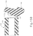
- pawl member (190) is pivoted to a second position as shown in FIGS. 15B and 16B
- pawl ridge (198) disengages retention feature (131), enabling camshaft (130) to rotate under the influence of torsion spring (140) to provide the sequence of operation described above.
- pushbutton (106) includes a pull-pin opening (109) that is configured to receive pull-pin (108). Pushbutton (106) is prevented from translating laterally relative to housing (104) when pull-pin (108) is disposed within pull-pin opening (109). Pull-pin (108) thus provides a lockout for pushbutton (106). To unlock pushbutton (106), pull-pin (108) may be pulled distally out of housing (104).
- pushbutton (106) also includes a proximally facing boss rib (107) that extends vertically. When pushbutton (106) is laterally centered within housing (104), boss rib (107) engages boss rib (194), as shown in FIGS. 15A and 16A . This engagement prevents pawl member (190) from pivoting distally about pins (192). Pushbutton (106) and pawl member (190) together thus effectively lock camshaft (130) when pushbutton (106) is laterally centered within housing (104).
- camshaft (130) forces pawl member (190) to pivot out of the way to the position shown in FIGS. 15B and 16B when pushbutton (106) is no longer blocking pawl member (190). This enables camshaft (130) to complete the operational drive sequence described above.
- pushsbutton (106) is depicted as being pushed in one lateral direction, it should be understood that the same triggering operation may be provided when pushbutton (106) is pushed in the opposite lateral direction from the center position. With portions of pushbutton (106) being exposed through housing (104) on each side of handpiece (102), this allows the operator to select which side of pushbutton (106) to press.
- PETDD epithelial Deformation Deformation
- a PETDD (100) may include various other features in addition to or in lieu of those described above.
- any of the devices herein may also include one or more of the various features disclosed in any of the various references.
- Some additional merely illustrative variations of PETDD (100) will be described in greater detail below, while other variations of PETDD (100) will be apparent to those of ordinary skill in the art in view of the teachings herein.
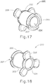
- FIGS. 17-20 show PE tube (200) in greater detail.
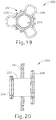
- PE tube (200) of this example includes a cylindraceous body (202) that defines a passageway (204).
- a flange (206) is located at the proximal end of body (202) while a set of petals (208) are located at the distal end of body (202).
- Flange (206) includes a plurality of inwardly directed recesses (207).
- Recesses (207) are configured to facilitate flexing of flange (206) from an outwardly extended position to a generally cylindraceous position where the material forming flange (206) extends longitudinally. While three recesses (207) are shown, it should be understood that any other suitable number of recesses (207) may be provided. Similarly, while three petals (208) are shown, it should be understood that any other suitable number of petals (208) may be provided.
- PE tube (200) is formed of a resilient material that is biased to assume the rivet like configuration shown in FIGS. 17-20 .
- flange (206) and petals (208) may be flexed inwardly toward the longitudinal axis of body (202) to provide PE tube (200) with a cylindraceous configuration.
- flange (206) and petals (208) may be flexed such that their outer surfaces are at the same radial distance from the longitudinal axis as the outer perimeter of body (202). This radial distance may be slightly less than the radial distance associated with the inner diameter of shield tube (160), such that PE tube (200) may collapse to fit within shield tube (160).
- PE tube (200) When PE tube (200) is disposed in a tympanic membrane (TM), petals (208) are located medially (i.e., on the middle ear side) while flange (206) is located laterally (i.e., on the outer ear side).
- PE tube (200) may also be configured in accordance with at least some of the teachings of U.S. Pat. App. No. 13/800,113 , entitled “Tympanic Membrane Pressure Equalization Tube,” filed on March 13, 2013, published as U.S. Pub. No. 2014/0094733 on April 3, 2014 .
- Other suitable forms that PE tube (200) may take will be apparent to those of ordinary skill in the art in view of the teachings herein.
- the tympanic membrane (TM) may extend along a plane that is oblique to the direction of insertion of PETDD (100).
- the plane of the tympanic membrane (TM) may be obliquely angled relative to the longitudinal axis of shaft assembly (115).
- the tympanic membrane (TM) may define an angle between approximately 79 degrees and approximately 54 degrees with the longitudinal axis of shaft assembly (115). This oblique orientation of the tympanic membrane (TM) may pose difficulties with respect to some versions of a PETDD (100) that has a flat tip and/or a straight shaft assembly (115).
- a rigid shaft assembly (115) may also adversely impact the ergonomics of PETDD (100) by forcing an operator to hold PETDD (100) at an uncomfortable angle to achieve a desired angle between shaft assembly (115) and the tympanic membrane (TM). Incorporating flexible and/or rotatable features into shaft assembly (115) may thus enhance the ergonomics of PETDD (100). In particular, a flexible and/or rotatable shaft assembly (115) may enable an operator to hold PETDD (100) at a more comfortable angle while still maintaining proper orientation of shaft assembly (115) relative to the patient's tympanic membrane (TM).
- Such features may facilitate positioning of an endoscope and/or other instrument with shaft assembly (115) in the patient's car canal, thus promoting visualization of the tympanic membrane (TM).
- TM tympanic membrane
- the following examples include merely illustrative variations of PETDD (100) that may provide flexibility and/or rotatability in shaft assembly (115).
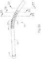
- FIG. 21 depicts an example of a PETDD (300) according to the invention, the PETDD (300) having a bendable shaft assembly (315). All of the other components in this variation may be the same as those described above for PETDD (100), unless otherwise noted herein.
- PETDD (300) comprises a handpiece (302) and a shaft assembly (315) extending distally from handpiece (302).
- Hanpdiece (302) is formed by two housing (304) halves that are joined together and that include internal features configured to support various components of PETDD (300) similarly as described above with respect to handpiece (102) of PETDD (100).
- Handpiece (302) is configured to be handheld, such that an operator may fully operate PETDD (300) using a single hand.
- a pushbutton (306) is slidably disposed in housing (304) and includes exposed portions extending laterally from each side of handpiece (302).
- Pushbutton (306) is operable to be pushed along a path that is transverse to handpiece (302) in order to actuate PETDD (300) similarly as described above with respect to pushbutton (106) of PETDD (100).
- a pull-pin (308) extends distally from handpiece (302) and is configured to prevent pushbutton (306) from being actuated, thereby preventing PETDD (300) from being actuated, so long as pull-pin (308) is disposed in handpiece (302). Pull-pin (308) is nevertheless removable from handpiece (302) to effectively unlock pushbutton (306) and thereby enable actuation of PETDD (300).
- shaft assembly (315) includes a cannula (320) comprising an elongate tube having a bendable section (324), a thumbwheel (310), and a tip member (322) at the distal end of cannula (320).
- Thumbwheel (310) is fixedly secured to cannula (320) where cannula (320) and handpiece (302) meet.
- thumbwheel (310) is operable to rotate cannula (320) about the longitudinal axis of cannula (320) relative to handpiece (302) when acted upon by a user.
- handpiece (302) includes a bushing (312) which both supports cannula (320) in handpiece (302) and permits cannula (320) to rotate.
- thumbwheel (310) may be fixedly secured to cannula (320) by adhesive bonding, over-molding, or any other means.
- a proximal end of cannula (320) may include a flared end or other geometric features to aid with attachment.
- thumbwheel (310) may be integral to cannula (320) such that the two parts form a unitary part.
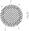
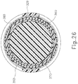
- bendable section (324) comprises a plurality of cut outs (326), which define a plurality of ribs (328) on either side of cannula (320). Cut outs (326) only extend through a portion of cannula (320) such that a solid longitudinally extending member (329) of cannula (320) remains. Longitudinally extending member (329) maintains lateral stability of cannula (320), yet cut outs (326) and ribs (328) operate cooperatively to permit cannula (320) to bend along a plane as will be described in greater detail below.
- bendable section (324) as depicted shows merely one exemplary geometry suitable to permit cannula (320) to bend.
- bendable section (324) could have any other suitable design such as a fluid linkage and/or other bendable structure as will be apparent to those of ordinary skill in the art in view of the teachings herein.
- Tip member (322) is configured to contact a patient's tympanic membrane (TM).
- tip member (322) may be integral to cannula (320) such that cannula (320) and tip member (322) are of a unitary part.
- member (322) may be a separate component fixedly secured to the distal end of cannula (320).
- tip member (322) may be configured to be clear or opaque. Where clear, tip member (322) may enable enhanced visualization of a patient's tympanic membrane (TM).
- tip member (322) is shown as being orthogonal relative to the longitudinal axis of cannula (320), it should be understood that other distal end geometries may be used.
- the distal end of tip member (322) may be obliquely angled relative to the longitudinal axis of cannula (320) to accommodate patients with obliquely angled TM's.
- Examples of such obliquely angled distal ends of tip member may be configured in accordance with at least some of the teachings of U.S. Pat. App. No. 13/804,553 , entitled "Features to Improve and Sense Tympanic Membrane Apposition by Tympanostomy Tube Delivery Instument," filed on March 14, 2013, .
- any other suitable configuration of tip member (322) may be used as will be apparent to those of ordinary skill in the art in view of the teachings herein.
- Cannula (320) and/or tip member (322) may be formed of the same materials or different materials.
- cannula (320) and/or tip member (322) may be formed of a soft or elastomeric material such as rubber, soft plastic, nylon, polyether ether ketone (PEEK), etc.
- cannula (320) and/or tip member (322) may be formed of a hard, more resilient material such as stainless steel, aluminum, or the like.
- cannula (320) could comprise a rigid material proximal to bendable section (324), a flexible material at bendable section (324), and a rigid material distal to bendable section (324).
- bendable section (324) could be formed of a malleable material.
- bendable section (324) may be formed of a plurality of short, rigid segments that are pivotally coupled together.
- cannula (320) and/or tip member (322) is comprised of a soft or elastomeric material, such a material may dampen vibrations that might otherwise be transmitted from cannula (120) to the patient's tympanic membrane (TM) during firing of PETDD (300).
- tip member (322) may include some other kind of dampening feature as will be apparent to those of ordinary skill in the art in view of the teachings herein.
- housing (304) supports a camshaft (330) and various other components.
- Camshaft (330) includes a dilator track (332), a shield tube track (334), a stopper track (337), a pusher track (336), and a piercer track (338).
- Tracks (332, 334, 336, 337, 338) are formed as recesses in camshaft (330) and each track (332, 334, 336, 337, 338) has a unique configuration in order to provide the same particular sequence of operation as similarly described above with respect to camshaft (130) of PETDD (100).
- a torsion spring (340) is coupled to the proximal end of camshaft (330).
- Torsion spring (340) is also grounded against housing (304). Torsion spring (340) resiliently provides a rotational bias to camshaft (330). In particular, torsion spring (340) urges camshaft (330) to rotate in the clockwise direction (viewed from the distal end of PETDD (300) toward the proximal end of PETDD (300)) about the longitudinal axis of camshaft (330). As was similarly described above with respect to PETDD (100), a trigger mechanism selectively resists such rotation. While torsion spring (340) is used to bias camshaft (330) in the present example, it should be understood that any other suitable types of components may be used to bias camshaft (330).
- camshaft (330) of PETDD (100) various components are engaged with camshaft (330) and are thereby actuated by rotation of camshaft (330).
- a dilator tube (350), a shield tube (360), a pusher tube (370), and a piercer (380) are all engaged with camshaft (330).
- Tubes (350, 360, 370) and piercer (380) are all coaxially disposed within cannula (320) such that tubes (350, 360, 370) and piercer (380) together form shaft assembly (315).
- Piercer (380) is coaxially and slidably disposed within pusher tube (370), which is coaxially and slidably disposed within shield tube (360), which is coaxially and slidably disposed within dilator tube (350), which is coaxially and slidably disposed within cannula (320).
- Tubes (350, 360, 370) and piercer (380) all translate relative to cannula (320) in a particular sequence in order to deploy a PE tube as was similarly described above. This sequence is driven by rotation of camshaft (330).
- a cam follower (352) is fixedly secured to the proximal end of dilator tube (350).
- Cam follower (352) includes a laterally projecting pin (not shown) that is disposed in dilator track (332), such that rotation of camshaft (330) causes cam follower (352) and dilator tube (350) to translate.
- a cam follower (362) is fixedly secured to the proximal end of shield tube (360).
- Cam follower (362) includes a laterally projecting pin (not shown) that is disposed in shield tube track (334), such that rotation of camshaft (330) causes cam follower (362) and shield tube (360) to translate.
- a cam follower (372) is fixedly secured to the proximal end of pusher tube (370).
- Cam follower (372) includes a laterally projecting pin (not shown) that is disposed in pusher tube track (336), such that rotation of camshaft (330) causes cam follower (372) and pusher tube (370) to translate.
- a cam follower (382) is fixedly secured to the proximal end of piercer (380).
- Cam follower (382) includes a laterally projecting pin (not shown) that is disposed in piercer track (338), such that rotation of camshaft (330) causes cam follower (382) and piercer (380) to translate.
- Stopper track (337) is simply annular in this example and includes a fixed elastomeric plug (335). An inwardly protruding boss (not shown) of housing (304) is disposed in stopper track (337). This boss remains disposed in stopper track (337) during rotation of camshaft (330).
- tubes (350, 360, 370) and piercer (380) have distal ends configured similarly to the distal ends of tubes (150, 160, 170) and piercer described above.
- dilator tube (350) includes a plurality of flexible leaves (not shown) that are resiliently biased inwardly.
- the distal end of shield tube (360) and pusher tube (370) include a circular edge (not shown) and a distal face (not shown), respectively. Similar to distal face (176) discussed above, distal face of pusher tube comprises a more prominent contact surface relative to circular edge of shield tube (160).
- piercer (180) includes a sharp multi-faceted piercer tip (not shown) that is configured to pierce through a patient's tympanic membrane (TM).
- tubes (350, 360, 370) and piercer (380) are described above as having distal ends that are similar to those of tubes (150, 160, 170) and piercer (180), no such limitation is intended. Indeed, tubes (350, 360, 370) and piercer (380) may comprise any suitable distal end configurations as will be apparent to those of ordinary skill in the art in view of the teachings herein.
- each tube (350, 360, 370) and piercer (380) is flexible.
- at least a portion of each tube (350, 360, 370) and piercer (380) may be formed of nylon, PEEK, some other flexible polymer, a flexible metal, and/or any other suitable flexible material(s) as will be apparent to those of ordinary skill in the art in view of the teachings herein.
- Such a flexible portion of each tube (350, 360, 370), and piercer (380) extends through bendable section (324) of cannula (320).
- tubes (350, 360, 370) and piercer (380) enable tubes (350, 360, 370) and piercer (380) to translate longitudinally through bendable section (324) while bendable section (324) is in a bent state.
- tubes (350, 360, 370) and piercer (380) each have a rigid distal end or rigid distal portion, in addition to having a flexible region located proximal to the rigid distal end or portion.
- each tube (350, 360, 370) and piercer (380) may be formed of a rigid metal, a rigid polymer, and/or any other suitable rigid material(s) as will be apparent to those of ordinary skill in the art in view of the teachings herein.
- a proximal section of each tube (350, 360, 370) and piercer (380) may be rigid, in addition to a distal portion or distal end of each tube (350, 360, 370) and piercer (380) being rigid, with the intermediate region of the length of each tube (350, 360, 370) and piercer (380) being flexible.
- Various suitable combinations of rigidity and flexibility in the construction of tubes (350, 360, 370) and piercer (380) will be apparent to those of ordinary skill in the art in view of the teachings herein.
- Tubes (350, 360, 370) are configured to be used in conjunction with PE tube (200) as similarly described above with respect to PETDD (100).
- PE tube (200), tubes (350, 360, 370), and piercer (380) may all be sequentially actuated within cannula (320).
- the particular sequence is controlled by tracks (332, 334, 336, 338) as camshaft (330) rotates and is substantially similar to the sequence described above with respect to FIG. 9 .
- PETDD (300) is still operable to penetrate a patient's tympanic membrane (TM) and deploy PE tube (200) using substantially the same mechanisms as those described above with respect to PETDD (100).
- PETDD (300) may be configured for use without PE tube (200).
- PETDD (300) may simply be used to puncture a patient's tympanic membrane (TM) for fluid collection or other similar procedures.
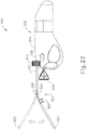
- FIG. 22 shows that cannula (320) is bendable to a variety of angles.
- cannula (230) may bend to achieve angles from approximately 0 degrees to approximately 60 degrees; or from approximately 0 degrees to approximately 45 degrees.
- cannula (320) may be configured to be malleable such that it may be bent to a specific angular location and remain at that specific location without a continuously applied force.
- cannula (320) may merely be flexible such that it may be sustained in a particular angular location only when a continuous force is applied. In either case, such properties may be achieved by, at least in part, the materials used for cannula (320), tubes (350, 360, 370), and/or piercer (380).
- cannula (320) may be comprised of malleable alloys such as stainless steel alloys, aluminum alloys, shape memory alloys, or the like. Additionally, such malleable properties may be achieved with other materials such as malleable plastics or polymers. Alternatively, to achieve properties that render cannula flexible, non-malleable alloys or plastics may be used. Further, materials may be varied between cannula (320), tubes (350, 360, 370), and piercer (380) to render cannula (320) malleable, semi-malleable, or flexible. Of course, cannula (320), tubes (350, 360, 370), and piercer (380) may be comprised of any suitable material to have any suitable properties as will be apparent to those of ordinary skill in the art in view of the teachings herein.
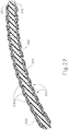
- tubes (350, 360, 370) and piercer (380) extend through bendable section (324) of cannula (320) and are configured to bend as cannula (320) bends. It should be understood that tubes (350, 360, 370) and piercer (380) are configured such that they may be sequentially actuated within cannula (320) even when cannula (320) is bent. In other words, cannula (320) tubes (350, 360, 370), and piercer (380) are configured to maintain a neutral axis throughout bendable section (324) such that each component maintains a consistent relationship with tip member (322) as cannula (320) is bent. In some versions, lubricant may be included between cannula (320), tubes (350, 360, 370), piercer (380) and cannula (320), although such lubricant is entirely optional.
- cannula (320) is rotatable via thumbwheel (310).
- cannula (320) is operable to both bend and rotate relative to its longitudinal axis.
- tubes (350, 360, 370) and piercer (380) may remain stationary while cannula (320) rotates.
- thumbwheel (310) may be configured to rotate all or some of tubes (350, 360, 370) and/or piercer (380) in conjunction with cannula (320).
- tubes (350, 360, 370) and/or piercer tube (380) may be configured to be independently rotatable relative to cannula (320).
- piercer tube (380) may be independently rotatable to optimize piercing. Such a combination of bendability and roatatability may increase visualization of, and access to, the tympanic membrane (TM) of a patient.
- cannula (320) may be pre-bent outside of a patient to account for an obliquely oriented tympanic membrane (TM) of the patient.
- Cannula (320) may be then inserted into the ear of the patient.
- An endoscope or other similar device may be used for visualization of the patient's tympanic membrane (TM) as cannula (320) is inserted through the ear canal.
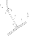
- cannula (320) may be rotated to fine tune the angle of tip member (322) to position tip member (322) into proper alignment with the patient's tympanic membrane (TM). As can be seen in FIG. 28 , cannula (320) may be further advanced such that tip member (322) engages the patient's tympanic membrane (TM) in full apposition.
- Pushbutton (306) may then be actuated by a user, and the PE Tube (200) may be delivered to the patient's tympanic membrane (TM).
- cannula (320) may be merely flexible and the ear canal may be used to provide a force sufficent to bend cannula (320) such that it may be positioned into alignment with the patient's tympanic membrane (TM).
- PETDD (300) may be used in various other ways as will be apparent to those of ordinary skill in the art in view of the teachings herein.
- versions described herein may be sterilized before and/or after a procedure.
- the device is sterilized using conventional ethylene oxide sterilization techniques and systems.
- the device is placed in a closed and sealed container, such as a plastic or TYVEK bag; and the container and device may then be placed in a field of radiation that can penetrate the container, such as gamma radiation, x-rays, or high-energy electrons.
- the radiation may kill bacteria on the device and in the container.
- the sterilized device may then be stored in the sterile container for later use.
- a device may also be sterilized using any other technique known in the art, including but not limited to beta or gamma radiation, steam, etc.
Landscapes
- Health & Medical Sciences (AREA)
- Life Sciences & Earth Sciences (AREA)
- Engineering & Computer Science (AREA)
- Vascular Medicine (AREA)
- Acoustics & Sound (AREA)
- Biophysics (AREA)
- Otolaryngology (AREA)
- Psychology (AREA)
- Surgery (AREA)
- Biomedical Technology (AREA)
- Heart & Thoracic Surgery (AREA)
- Physics & Mathematics (AREA)
- Animal Behavior & Ethology (AREA)
- General Health & Medical Sciences (AREA)
- Public Health (AREA)
- Veterinary Medicine (AREA)
- Infusion, Injection, And Reservoir Apparatuses (AREA)
- Surgical Instruments (AREA)
- Endoscopes (AREA)
Description
- Some children may exhibit recurrent episodes of otitis media and/or otitis media with effusion. Treatment of severe cases may involve the placement of a pressure equalization tube or tympanostomy tube through the tympanic membrane to provide adequate drainage of the middle ear by providing fluid communication between the middle and outer ear. In particular, such a tube may provide a vent path that promotes drainage of fluid from the middle ear via the Eustachian tube and may thus reduce stress imposed on the tympanic membrane from pressure within the middle ear. This may further reduce the likelihood of future infections and pressure induced ruptures of the tympanic membrane. Pressure equalization tubes may fall out spontaneously within about a year of placement. Exemplary pressure equalization tube delivery systems are disclosed in
U.S. Patent No. 8,052,693 , entitled "System and Method for the Simultaneous Automated Bilateral Delivery of Pressure Equalization Tubes," issued November 8, 2011, Additional exemplary pressure equalization tube delivery systems are disclosed inU.S. Patent No. 8,249,700 , entitled "System and Method for the Simultaneous Bilateral Integrated Tympanic Drug Delivery and Guided Treatment of Target Tissues within the Ears," issued August 21, 2012, Still additional exemplary pressure equalization tube delivery systems are disclosed inU.S. Pub. No. 2011/0015645 , entitled "Tympanic Membrane Pressure Equalization Tube Delivery System," published January 20, 2011, - Insertion of a pressure equalization tube may be performed using general anesthesia in some cases, which may require additional resources such as an operating room, the presence of an anesthesiologist, and time in a recovery room. Furthermore, the use of general anesthesia may include certain risks that a patient may or may not be comfortable with undertaking. Some pressure equalization tube delivery systems and methods provide a local anesthetic through iontophoresis. Examples of such systems and methods are disclosed in
U.S. Pub. No. 2010/0198135 , entitled "Systems and Methods for Anesthetizing Ear Tissue," published August 5, 2010, Additional examples of such systems and methods are disclosed inU.S. Patent No. 8,192,420 , entitled "Iontophoresis Methods," issued June 5, 2012, -
US2013/338678 discloses an insertion system which includes a handle assembly and a nose assembly removably attached to the handle assembly and including an insertion end. The handle assembly includes a main body, a nose interface and an actuating element. The nose assembly includes a nose, a positioning rod extending from the nose to a distal end, a cutting sheath surrounding a distal end of the positioning rod and including a cutting edge, an actuation member having a proximal end coupled to the actuating element when the nose assembly is attached to the handle assembly and a distal end attached to the cutting sheath, a ventilation tube positioned distal to the distal end of the positioning rod and proximal to the insertion end. The cutting sheath retracts from around the ventilation tube and along the positioning rod when the actuating element on the handle assembly is moved. - The invention is defined in the following claims; embodiments, examples or methods outwith the scope of said claims are not a part of the invention and are described for illustrative purposes only.
- It is believed the present invention will be better understood from the following description of certain examples taken in conjunction with the accompanying drawings, in which like reference numerals identify the same elements and in which:
-
FIG. 1 depicts a perspective view of an exemplary pressure equalization tube delivery device (PETDD); -
FIG. 2 depicts a perspective view of the PETDD ofFIG. 1 , with a housing half omitted; -
FIG. 3 depicts an exploded elevational view of actuation features of the PETDD ofFIG. 1 ; -
FIG. 4 depicts a perspective view of the distal end of a dilator of the actuation features ofFIG. 3 ; -
FIG. 5 depicts a perspective view of the distal end of a shield tube of the actuation features ofFIG. 3 ; -
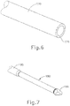
FIG. 6 depicts a perspective view of the distal end of a pusher of the actuation features ofFIG. 3 ; -
FIG. 7 depicts a perspective view of the distal end of a piercer of the actuation features ofFIG. 3 ; -
FIG. 8 depicts a cross-sectional side view of the actuation features ofFIG. 3 with an exemplary pressure equalization (PE) tube; -
FIG. 9 depicts a displacement and operational diagram associated with the actuation features ofFIG. 3 ; -
FIG. 10 depicts an exploded perspective view of a trigger mechanism of the actuation features ofFIG. 3 ; -
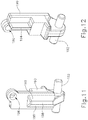
FIG. 11 depicts a perspective view of the proximal side of a pawl of the trigger mechanism ofFIG. 10 ; -
FIG. 12 depicts a perspective view of the distal side of the pawl ofFIG. 11 ; -
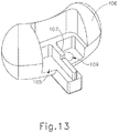
FIG. 13 depicts a perspective view of the proximal underside of a button actuator of the trigger mechanism ofFIG. 10 ; -
FIG. 14 depicts a bottom plan view of the trigger mechanism ofFIG. 10 , showing the pawl engaged with the camshaft; -
FIG. 15A depicts a cross-sectional view of the trigger mechanism ofFIG. 10 , taken along line 15-15 ofFIG. 14 , showing the pawl engaged with the camshaft; -
FIG. 15B depicts a cross-sectional view of the trigger mechanism ofFIG. 10 , taken along line 15-15 ofFIG. 14 , showing the pawl disengaged from the camshaft, with the button actuator omitted; -
FIG. 16A depicts a cross-sectional view of the pawl and button actuator ofFIGS. 11 and13 , taken along line 16-16 ofFIG. 15A , showing the button actuator arresting the pawl; -
FIG. 16B depicts a cross-sectional view of the pawl and button actuator ofFIGS. 11 and13 , taken along line 16-16 ofFIG. 15A , showing the button actuator translated laterally to enable movement of the pawl; -
FIG. 17 depicts a perspective view of the proximal side of an exemplary PE tube suitable for delivery by the PETDD ofFIG. 1 ; -
FIG. 18 depicts a perspective view of the distal side of the PE tube ofFIG. 17 ; -
FIG. 19 depicts a distal elevational view of the PE tube ofFIG. 17 ; -
FIG. 20 depicts a side elevational view of the PE tube ofFIG. 17 , positioned within a tympanic membrane; -
FIG. 21 depicts a perspective view of an exemplary alternative PETDD having a bendable and rotatable shaft assembly; -
FIG. 22 depicts a side elevational view of the PETDD ofFIG. 21 with an alternative position of the shaft assembly shown in phantom; -
FIG. 23 depicts a perspective view of the PETDD ofFIG. 21 , with a housing half omitted; -
FIG. 24 depicts an enlarged perspective view of the shaft assembly of the PETDD ofFIG. 21 ; -
FIG. 25 depicts a cross-sectional front view of the shaft assembly ofFIG. 24 , with the cross-section taken along line 25-25 ofFIG. 24 ; -
FIG. 26 depicts a cross-sectional front view of the shaft assembly ofFIG. 24 , with the cross-section taken along line 26-26 ofFIG. 24 ; -
FIG. 27 depicts a cross-sectional side view of the shaft assembly ofFIG. 24 , with the cross-section taken along line 27-27 ofFIG. 24 ; and -
FIG. 28 depicts a side elevational view of the shaft assembly ofFIG. 23 in contact with a tympanic membrane. - The following description of certain examples of the technology should not be used to limit its scope. Other examples, features, aspects, embodiments, and advantages of the technology will become apparent to those skilled in the art from the following description, which is by way of illustration, one of the best modes contemplated for carrying out the technology. As will be realized, the technology described herein is capable of other different and obvious aspects, all without departing from the technology. Accordingly, the drawings and descriptions should be regarded as illustrative in nature and not restrictive.
- It is further understood that any one or more of the teachings, expressions, embodiments, examples, etc. described herein may be combined with any one or more of the other teachings, expressions, embodiments, examples, etc. that are described herein. The following-described teachings, expressions, embodiments, examples, etc. should therefore not be viewed in isolation relative to each other. Various suitable ways in which the teachings herein may be combined will be readily apparent to those of ordinary skill in the art in view of the teachings herein.
- As noted above, a pressure equalization (PE) tube may be delivered to the tympanic membrane (TM) of a patient as a way of treating, for example, otitis media. In some instances, a delivery instrument may be used to insert PE tubes in the tympanic membrane (TM) without the use of general anesthesia.
FIG. 1 shows an exemplary pressure equalization tube delivery device (PETDD) (100) that may be used in such procedures. It should be understood that PETDD (100) may be used with an endoscope to provide visualization of the tympanic membrane (TM) during use of PETDD (100). It should also be understood that a patient may receive local anesthesia at the tympanic membrane (TM) through a process of iontophoresis before PETDD (100) is actuated to deploy a PE tube. By way of example only, such iontophoresis may be provided in accordance with at least some of the teachings ofU.S. Pub. No. 2010/0198135 , and/or in accordance with at least some of the teachings ofU.S. Patent No. 8,192,420 . Other suitable ways in which PETDD (100) may be used will be apparent to those of ordinary skill in the art in view of the teachings herein. - As shown in
FIG. 1 , PETDD (100) of this example comprises a handpiece (102) and a shaft assembly (115) extending distally from handpiece (102). Hanpdiece (102) is formed by two housing (104) halves that are joined together and that include internal features configured to support various components of PETDD (100) as will be described below. Handpiece (102) is configured to be handheld, such that an operator may fully operate PETDD (100) using a single hand. A pushbutton (106) is slidably disposed in housing (104) and includes exposed portions extending laterally from each side of handpiece (102). Pushbutton (106) is operable to be pushed along a path that is transverse to handpiece (102) in order to actuate PETDD (100) as will be described in greater detail below. A pull-pin (108) extends distally from handpiece (102) and is configured to prevent pushbutton (106) from being actuated, thereby preventing PETDD (100) from being actuated, so long as pull-pin (108) is disposed in handpiece (102). Pull-pin (108) is nevertheless removable from handpiece (102) to effectively unlock pushbutton (106) and thereby enable actuation of PETDD (100). Shaft assembly (115) of the present example includes a cannula (120) comprising an elongate tube having a clear tip member (122) at the distal end of cannula (120). Clear tip member (122) is configured to contact a patient's tympanic membrane (TM) while enabling visualization of the distal end of cannula (120). In some versions, tip member (122) is formed of a soft or elastomeric material such as rubber, soft plastic, etc. This may dampen vibrations that might otherwise be transmitted from cannula (120) to the patient's tympanic membrane (TM) during firing of PETDD (100). In addition or in the alternative, tip member (122) may include some other kind of dampening feature as will be apparent to those of ordinary skill in the art in view of the teachings herein. - As can be seen in
FIG. 2 , housing (104) supports a camshaft (130) and various other components. Camshaft (130) includes a dilator track (132), a shield tube track (134), a stopper track (137), a pusher track (136), and a piercer track (138). Tracks (132, 134, 136, 137, 138) are formed as recesses in camshaft (130) and each track (132, 134, 136, 137, 138) has a unique configuration in order to provide a particular sequence of operation of translating components as will be described in greater detail below. A torsion spring (140) is coupled to the proximal end of camshaft (130). Torsion spring (140) is also grounded against housing (104). Torsion spring (140) resiliently provides a rotational bias to camshaft (130). In particular, torsion spring (140) urges camshaft (130) to rotate in the clockwise direction (viewed from the distal end of PETDD (100) toward the proximal end of PETDD (100)) about the longitudinal axis of camshaft (130). As will be described in greater detail below (200), a trigger mechanism selectively resists such rotation. While torsion spring (140) is used to bias camshaft (130) in the present example, it should be understood that any other suitable types of components may be used to bias camshaft (130). - As shown in
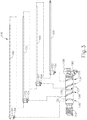
FIG. 3 , various components are engaged with camshaft (130) and are thereby actuated by rotation of camshaft (130). In particular, a dilator tube (150), a shield tube (160), a pusher tube (170), and a piercer (180) are all engaged with camshaft (130). Tubes (150, 160, 170) and piercer (180) are all coaxially disposed within cannula (120) of shaft assembly (115). Piercer (180) is coaxially and slidably disposed within pusher tube (170), which is coaxially and slidably disposed within shield tube (160), which is coaxially and slidably disposed within dilator tube (150), which is coaxially and slidably disposed within cannula (120). Tubes (150, 160, 170) and piercer (180) all translate relative to cannula (120) in a particular sequence in order to deploy a PE tube as will be described in greater detail below. This sequence is driven by rotation of camshaft (130). - A cam follower (152) is fixedly secured to the proximal end of dilator tube (150). Cam follower (152) includes a laterally projecting pin (154) that is disposed in dilator track (132), such that rotation of camshaft (130) causes cam follower (152) and dilator tube (150) to translate. Similarly, a cam follower (162) is fixedly secured to the proximal end of shield tube (160). Cam follower (162) includes a laterally projecting pin (164) that is disposed in shield tube track (134), such that rotation of camshaft (130) causes cam follower (162) and shield tube (160) to translate. A cam follower (172) is fixedly secured to the proximal end of pusher tube (170). Cam follower (172) includes a laterally projecting pin (174) that is disposed in pusher tube track (136), such that rotation of camshaft (130) causes cam follower (172) and pusher tube (170) to translate. Finally, a cam follower (182) is fixedly secured to the proximal end of piercer (180). Cam follower (182) includes a laterally projecting pin (184) that is disposed in piercer track (138), such that rotation of camshaft (130) causes cam follower (182) and piercer (180) to translate. Stopper track (137) is simply annular in this example and includes a fixed elastomeric plug (135). An inwardly protruding boss (not shown) of housing (104) is disposed in stopper track (137). This boss remains disposed in stopper track (137) during rotation of camshaft (130).
- As shown in
FIG. 4 , the distal end of dilator tube (150) includes a plurality of generally flexible leaves (156) that are separated by longitudinally extending gaps (158). Leaves (156) are resiliently biased to assume the inwardly deflected positioning shown inFIG. 4 ; but are operable to flex outwardly from this positioning as will be described in greater detail below. As shown inFIG. 5 , the distal end of shield tube (160) simply includes a circular edge (166). As shown inFIG. 6 , the distal end of pusher tube (170) includes a distal face (176). In the present example, the difference between the inner diameter of pusher tube (170) and the outer diameter of pusher tube (170) is greater than the difference between the inner diameter of shield tube (160) and the outer diameter of shield tube (160). Thus, distal face (176) presents a more prominent contact surface than circular edge (166). As shown inFIG. 7 , the distal end of piercer (180) includes a sharp, multi-faceted piercer tip (186) that is configured to pierce through a patient's tympanic membrane (TM). In the present example, piercer (180) also includes a neck-down region (188) having a reduced diameter. -
FIG. 8 shows the positioning of tubes (150, 160, 170), piercer (180), and PE tube (200) within cannula (120) before camshaft (130) starts rotating from a home position. As shown, piercer tip (186) of piercer (180) is positioned distal to leaves (156) of dilator tube (150), such that leaves (156) are positioned about neck-down region (188) of piercer (180). PE tube (200) is positioned within the distal end of shield tube (160), whose distal edge (166) is just proximal to leaves (156). Pusher tube (170) is proximal to PE tube (200), with distal face (176) of pusher tube (170) abutting the proximal end of PE tube (200). In the present example, PE tube (200) is resiliently biased to assume a rivet-like shape presenting transverse petals (208) and a flange (206) (seeFIG. 17-20 ). However, PE tube (200) is compressed against this bias, thereby assuming a generally cylindraceous configuration, when PE tube (200) is disposed within shield tube (160) as shown inFIG. 8 . -
FIG. 9 depicts a sequence of operation that occurs upon rotation of camshaft (130) from a home position to an actuated position, where tracks (132, 134, 136, 138) are shown developed into a flat pattern for purpose of illustration. The sequence starts at the top region ofFIG. 9 , which shows the distal end of clear tip member (122) contacting the patient's tympanic membrane (TM). At this stage, tubes (150, 160, 170), piercer (180), and PE tube (200) are at the positions shown inFIG. 8 . Once camshaft (130) starts rotating at the urging of torsion spring (140), pins (154, 164, 174, 184) begin to ride along their respective tracks (132, 134, 136, 138), such that piercer tip (186) and leaves (156) are driven distally through the patient's tympanic membrane (TM). While not directly shown inFIG. 8 , it should be understood that tubes (160, 170) are also driven distally during this transition, though tubes (160, 170) remain proximal to clear tip member (122) at this stage. As camshaft (130) continues to rotate, piercer (180) begins retracting proximally while tubes (160, 170) continue to advance distally. As shown, shield tube (160) spreads leaves (156) outwardly from their default positions. This further dilates the puncture site in the tympanic membrane (TM). Shield tube (160) continues to contain PE tube (200) at this stage. As camshaft (130) continues to rotate, piercer (180) and dilator (150) retract proximally behind clear tip member (122). Shield tube (160) also begins to retract proximally, while pusher tube (170) remains longitudinally stationary. This relative movement uncovers the distal end of PE tube (200), such that the resilient bias of petals (208) causes petals (208) to flex to transverse positions, thereby effectively forming a flange on the far side of the tympanic membrane (TM). Piercer (180) eventually returns to the fully proximal position, dilator (170) eventually returns to the fully proximal position, and pusher tube (170) eventually reaches a fully distal position. As camshaft (130) continues to rotate, shield tube (160) continues to retract proximally while pusher tube (170) remains longitudinally stationary. This relative movement uncovers the proximal end of PE tube (200), such that the resilient bias of PE tube (200) is allowed to form flange (206) on the near side of the tympanic membrane (TM). - Camshaft (130) stops rotating when the inwardly protruding boss of housing (104) engages plug (135) in stopper track (137). The elastomeric nature of plug (135) provides a relatively soft stop, such that plug (135) acts as a damper. This may reduce jolting of PETDD (100) when camshaft (130) comes to a stop and/or may prevent camshaft (130) from making a popping or snapping sound when camshaft (130) comes to a stop. Upon completion of the above described sequence shown in
FIG. 9 , cannula (120) is withdrawn from the patient's ear, leaving the actuated PE tube (200) in place in the patient's tympanic membrane (TM). Petals (208) and flange (206) cooperate to maintain the position of PE tube (200) in TM, while the passageway (204) formed by the interior of PE tube (200) (seeFIGS. 8 and17-20 ) provides a path for fluid communication (e.g., venting) between the patient's middle ear and outer ear. This fluid path further provides pressure equalization between the patient's middle ear and outer ear and/or promotes drainage of fluid from the middle ear via the Eustachian tube. - As noted above, PETDD (100) of the present example includes a trigger mechanism that is configured to selectively resist rotation of camshaft (130) by torsion spring (140). As best seen in
FIGS. 10-16B , the trigger mechanism of this example comprises a pawl member (190) that selectively engages pushbutton (106) and camshaft (130). Pawl member (190) includes laterally extending pins (192) that couple pawl member (190) with housing (104). While housing (104) prevents pawl member (190) from moving laterally within housing (104), housing (104) permits pawl member (190) to pivot freely about pins (192) within housing (104). Pawl member (190) includes a distally facing boss rib (194) that extends vertically. Pawl member (190) also includes a pull-pin opening (196) and a proximally facing pawl ridge (198). Boss rib (194) is configured to selectively engage a proximally facing boss rib (107) of pushbutton (106) as will be described in greater detail below. Pull-pin opening (196) is configured to receive pull-pin (108), which assists to prevent pawl member (190) from pivoting about pins (192) when pull-pin (108) is disposed in pull-pin opening (196). Pawl ridge (198) includes chamfered lateral faces (199) and is configured to selectively engage a retention feature (131) of camshaft (130). In particular, when pawl member (190) is in a first position as shown inFIGS. 14 ,15A , and16A , pawl ridge (198) is engaged with retention feature (131) and prevents camshaft (130) from rotating despite the rotational bias provided by torsion spring (140). When pawl member (190) is pivoted to a second position as shown inFIGS. 15B and16B , pawl ridge (198) disengages retention feature (131), enabling camshaft (130) to rotate under the influence of torsion spring (140) to provide the sequence of operation described above. - As best seen in
FIGS. 10 and13 , pushbutton (106) includes a pull-pin opening (109) that is configured to receive pull-pin (108). Pushbutton (106) is prevented from translating laterally relative to housing (104) when pull-pin (108) is disposed within pull-pin opening (109). Pull-pin (108) thus provides a lockout for pushbutton (106). To unlock pushbutton (106), pull-pin (108) may be pulled distally out of housing (104). As noted above, pushbutton (106) also includes a proximally facing boss rib (107) that extends vertically. When pushbutton (106) is laterally centered within housing (104), boss rib (107) engages boss rib (194), as shown inFIGS. 15A and16A . This engagement prevents pawl member (190) from pivoting distally about pins (192). Pushbutton (106) and pawl member (190) together thus effectively lock camshaft (130) when pushbutton (106) is laterally centered within housing (104). - When pushbutton (106) is laterally displaced relative to housing (104) (i.e., when a user depresses an exposed portion of pushbutton (106) laterally relative to housing (104)), bosses (107, 194) disengage such that pushbutton (106) no longer blocks pivoting of pawl member (190). Due to the torsional bias of camshaft (130), the ramped configuration of retention feature (131), and the chamfered lateral faces (199) of pawl ridge (198), camshaft (130) forces pawl member (190) to pivot out of the way to the position shown in
FIGS. 15B and16B when pushbutton (106) is no longer blocking pawl member (190). This enables camshaft (130) to complete the operational drive sequence described above. While pushsbutton (106) is depicted as being pushed in one lateral direction, it should be understood that the same triggering operation may be provided when pushbutton (106) is pushed in the opposite lateral direction from the center position. With portions of pushbutton (106) being exposed through housing (104) on each side of handpiece (102), this allows the operator to select which side of pushbutton (106) to press. - It should be understood that the foregoing components, features, and operabilities of PETDD (100) are merely illustrative examples. A PETDD (100) may include various other features in addition to or in lieu of those described above. By way of example only, any of the devices herein may also include one or more of the various features disclosed in any of the various references. Some additional merely illustrative variations of PETDD (100) will be described in greater detail below, while other variations of PETDD (100) will be apparent to those of ordinary skill in the art in view of the teachings herein.
-
FIGS. 17-20 show PE tube (200) in greater detail. PE tube (200) of this example includes a cylindraceous body (202) that defines a passageway (204). A flange (206) is located at the proximal end of body (202) while a set of petals (208) are located at the distal end of body (202). Flange (206) includes a plurality of inwardly directed recesses (207). Recesses (207) are configured to facilitate flexing of flange (206) from an outwardly extended position to a generally cylindraceous position where the material forming flange (206) extends longitudinally. While three recesses (207) are shown, it should be understood that any other suitable number of recesses (207) may be provided. Similarly, while three petals (208) are shown, it should be understood that any other suitable number of petals (208) may be provided. - PE tube (200) is formed of a resilient material that is biased to assume the rivet like configuration shown in
FIGS. 17-20 . However, flange (206) and petals (208) may be flexed inwardly toward the longitudinal axis of body (202) to provide PE tube (200) with a cylindraceous configuration. In particular, flange (206) and petals (208) may be flexed such that their outer surfaces are at the same radial distance from the longitudinal axis as the outer perimeter of body (202). This radial distance may be slightly less than the radial distance associated with the inner diameter of shield tube (160), such that PE tube (200) may collapse to fit within shield tube (160). When PE tube (200) is disposed in a tympanic membrane (TM), petals (208) are located medially (i.e., on the middle ear side) while flange (206) is located laterally (i.e., on the outer ear side). By way of example only, PE tube (200) may also be configured in accordance with at least some of the teachings ofU.S. Pat. App. No. 13/800,113 U.S. Pub. No. 2014/0094733 on April 3, 2014 . Other suitable forms that PE tube (200) may take will be apparent to those of ordinary skill in the art in view of the teachings herein. - Those of ordinary skill in the art will appreciate that the tympanic membrane (TM) may extend along a plane that is oblique to the direction of insertion of PETDD (100). In other words, the plane of the tympanic membrane (TM) may be obliquely angled relative to the longitudinal axis of shaft assembly (115). By way of example only, the tympanic membrane (TM) may define an angle between approximately 79 degrees and approximately 54 degrees with the longitudinal axis of shaft assembly (115). This oblique orientation of the tympanic membrane (TM) may pose difficulties with respect to some versions of a PETDD (100) that has a flat tip and/or a straight shaft assembly (115). For instance, inadequate apposition between the distal edge of tip member (122) and the tympanic membrane (TM) may lead to unsuccessful deployment of PE tube (200). This may prompt some operators of PETDD (100) to apply significant pressure against the tympanic membrane (TM), to deform the tympanic membrane (TM) into a position of substantial apposition with the flat-faced tip member (122) of PETDD (100). It may be desirable to maximize the apposition between the distal edge of tip member (122) and the tympanic membrane (TM), such as by enabling the distal edge of tip member (122) to complement the orientation of the tympanic membrane (TM) as much as possible, without requiring an operator to apply significant pressure against the tympanic membrane (TM) in order to achieve adequate apposition.
- A rigid shaft assembly (115) may also adversely impact the ergonomics of PETDD (100) by forcing an operator to hold PETDD (100) at an uncomfortable angle to achieve a desired angle between shaft assembly (115) and the tympanic membrane (TM). Incorporating flexible and/or rotatable features into shaft assembly (115) may thus enhance the ergonomics of PETDD (100). In particular, a flexible and/or rotatable shaft assembly (115) may enable an operator to hold PETDD (100) at a more comfortable angle while still maintaining proper orientation of shaft assembly (115) relative to the patient's tympanic membrane (TM). Additionally, such features may facilitate positioning of an endoscope and/or other instrument with shaft assembly (115) in the patient's car canal, thus promoting visualization of the tympanic membrane (TM). The following examples include merely illustrative variations of PETDD (100) that may provide flexibility and/or rotatability in shaft assembly (115).
-
FIG. 21 depicts an example of a PETDD (300) according to the invention, the PETDD (300) having a bendable shaft assembly (315). All of the other components in this variation may be the same as those described above for PETDD (100), unless otherwise noted herein. As can be seen, PETDD (300) comprises a handpiece (302) and a shaft assembly (315) extending distally from handpiece (302). Hanpdiece (302) is formed by two housing (304) halves that are joined together and that include internal features configured to support various components of PETDD (300) similarly as described above with respect to handpiece (102) of PETDD (100). Handpiece (302) is configured to be handheld, such that an operator may fully operate PETDD (300) using a single hand. A pushbutton (306) is slidably disposed in housing (304) and includes exposed portions extending laterally from each side of handpiece (302). Pushbutton (306) is operable to be pushed along a path that is transverse to handpiece (302) in order to actuate PETDD (300) similarly as described above with respect to pushbutton (106) of PETDD (100). A pull-pin (308) extends distally from handpiece (302) and is configured to prevent pushbutton (306) from being actuated, thereby preventing PETDD (300) from being actuated, so long as pull-pin (308) is disposed in handpiece (302). Pull-pin (308) is nevertheless removable from handpiece (302) to effectively unlock pushbutton (306) and thereby enable actuation of PETDD (300). - As can be seen in
FIGS. 21 and22 , shaft assembly (315) includes a cannula (320) comprising an elongate tube having a bendable section (324), a thumbwheel (310), and a tip member (322) at the distal end of cannula (320). Thumbwheel (310) is fixedly secured to cannula (320) where cannula (320) and handpiece (302) meet. As will be described in greater detail below, thumbwheel (310) is operable to rotate cannula (320) about the longitudinal axis of cannula (320) relative to handpiece (302) when acted upon by a user. In the present example, handpiece (302) includes a bushing (312) which both supports cannula (320) in handpiece (302) and permits cannula (320) to rotate. In some versions, thumbwheel (310) may be fixedly secured to cannula (320) by adhesive bonding, over-molding, or any other means. Additionally, a proximal end of cannula (320) may include a flared end or other geometric features to aid with attachment. Yet in other examples, thumbwheel (310) may be integral to cannula (320) such that the two parts form a unitary part. - As best seen in
FIGS. 24-26 , bendable section (324) comprises a plurality of cut outs (326), which define a plurality of ribs (328) on either side of cannula (320). Cut outs (326) only extend through a portion of cannula (320) such that a solid longitudinally extending member (329) of cannula (320) remains. Longitudinally extending member (329) maintains lateral stability of cannula (320), yet cut outs (326) and ribs (328) operate cooperatively to permit cannula (320) to bend along a plane as will be described in greater detail below. It should be understood that bendable section (324) as depicted shows merely one exemplary geometry suitable to permit cannula (320) to bend. In other examples, bendable section (324) could have any other suitable design such as a fluid linkage and/or other bendable structure as will be apparent to those of ordinary skill in the art in view of the teachings herein. - Tip member (322) is configured to contact a patient's tympanic membrane (TM). In some versions, tip member (322) may be integral to cannula (320) such that cannula (320) and tip member (322) are of a unitary part. In other versions tip, member (322) may be a separate component fixedly secured to the distal end of cannula (320). In either case, tip member (322) may be configured to be clear or opaque. Where clear, tip member (322) may enable enhanced visualization of a patient's tympanic membrane (TM). Although the distal end of tip member (322) is shown as being orthogonal relative to the longitudinal axis of cannula (320), it should be understood that other distal end geometries may be used. For instance, the distal end of tip member (322) may be obliquely angled relative to the longitudinal axis of cannula (320) to accommodate patients with obliquely angled TM's. Examples of such obliquely angled distal ends of tip member may be configured in accordance with at least some of the teachings of
U.S. Pat. App. No. 13/804,553 - Cannula (320) and/or tip member (322) may be formed of the same materials or different materials. For instance, in some versions cannula (320) and/or tip member (322) may be formed of a soft or elastomeric material such as rubber, soft plastic, nylon, polyether ether ketone (PEEK), etc. Yet in other versions cannula (320) and/or tip member (322) may be formed of a hard, more resilient material such as stainless steel, aluminum, or the like. In still other examples, cannula (320) could comprise a rigid material proximal to bendable section (324), a flexible material at bendable section (324), and a rigid material distal to bendable section (324). Alternatively, bendable section (324) could be formed of a malleable material. As yet another merely illustrative example, bendable section (324) may be formed of a plurality of short, rigid segments that are pivotally coupled together. When cannula (320) and/or tip member (322) is comprised of a soft or elastomeric material, such a material may dampen vibrations that might otherwise be transmitted from cannula (120) to the patient's tympanic membrane (TM) during firing of PETDD (300). In addition or in the alternative, tip member (322) may include some other kind of dampening feature as will be apparent to those of ordinary skill in the art in view of the teachings herein.
- As can be seen in
FIG. 23 , housing (304) supports a camshaft (330) and various other components. Camshaft (330) includes a dilator track (332), a shield tube track (334), a stopper track (337), a pusher track (336), and a piercer track (338). Tracks (332, 334, 336, 337, 338) are formed as recesses in camshaft (330) and each track (332, 334, 336, 337, 338) has a unique configuration in order to provide the same particular sequence of operation as similarly described above with respect to camshaft (130) of PETDD (100). A torsion spring (340) is coupled to the proximal end of camshaft (330). Torsion spring (340) is also grounded against housing (304). Torsion spring (340) resiliently provides a rotational bias to camshaft (330). In particular, torsion spring (340) urges camshaft (330) to rotate in the clockwise direction (viewed from the distal end of PETDD (300) toward the proximal end of PETDD (300)) about the longitudinal axis of camshaft (330). As was similarly described above with respect to PETDD (100), a trigger mechanism selectively resists such rotation. While torsion spring (340) is used to bias camshaft (330) in the present example, it should be understood that any other suitable types of components may be used to bias camshaft (330). - As similarly described above with respect to camshaft (130) of PETDD (100), various components are engaged with camshaft (330) and are thereby actuated by rotation of camshaft (330). In particular, a dilator tube (350), a shield tube (360), a pusher tube (370), and a piercer (380) are all engaged with camshaft (330). Tubes (350, 360, 370) and piercer (380) are all coaxially disposed within cannula (320) such that tubes (350, 360, 370) and piercer (380) together form shaft assembly (315). Piercer (380) is coaxially and slidably disposed within pusher tube (370), which is coaxially and slidably disposed within shield tube (360), which is coaxially and slidably disposed within dilator tube (350), which is coaxially and slidably disposed within cannula (320). Tubes (350, 360, 370) and piercer (380) all translate relative to cannula (320) in a particular sequence in order to deploy a PE tube as was similarly described above. This sequence is driven by rotation of camshaft (330).
- A cam follower (352) is fixedly secured to the proximal end of dilator tube (350). Cam follower (352) includes a laterally projecting pin (not shown) that is disposed in dilator track (332), such that rotation of camshaft (330) causes cam follower (352) and dilator tube (350) to translate. Similarly, a cam follower (362) is fixedly secured to the proximal end of shield tube (360). Cam follower (362) includes a laterally projecting pin (not shown) that is disposed in shield tube track (334), such that rotation of camshaft (330) causes cam follower (362) and shield tube (360) to translate. A cam follower (372) is fixedly secured to the proximal end of pusher tube (370). Cam follower (372) includes a laterally projecting pin (not shown) that is disposed in pusher tube track (336), such that rotation of camshaft (330) causes cam follower (372) and pusher tube (370) to translate. Finally, a cam follower (382) is fixedly secured to the proximal end of piercer (380). Cam follower (382) includes a laterally projecting pin (not shown) that is disposed in piercer track (338), such that rotation of camshaft (330) causes cam follower (382) and piercer (380) to translate. Stopper track (337) is simply annular in this example and includes a fixed elastomeric plug (335). An inwardly protruding boss (not shown) of housing (304) is disposed in stopper track (337). This boss remains disposed in stopper track (337) during rotation of camshaft (330).
- Although not shown, tubes (350, 360, 370) and piercer (380) have distal ends configured similarly to the distal ends of tubes (150, 160, 170) and piercer described above. For instance, dilator tube (350) includes a plurality of flexible leaves (not shown) that are resiliently biased inwardly. Likewise, the distal end of shield tube (360) and pusher tube (370) include a circular edge (not shown) and a distal face (not shown), respectively. Similar to distal face (176) discussed above, distal face of pusher tube comprises a more prominent contact surface relative to circular edge of shield tube (160). Additionally, piercer (180) includes a sharp multi-faceted piercer tip (not shown) that is configured to pierce through a patient's tympanic membrane (TM). Although tubes (350, 360, 370) and piercer (380) are described above as having distal ends that are similar to those of tubes (150, 160, 170) and piercer (180), no such limitation is intended. Indeed, tubes (350, 360, 370) and piercer (380) may comprise any suitable distal end configurations as will be apparent to those of ordinary skill in the art in view of the teachings herein.
- In the present example, at least a portion of each tube (350, 360, 370) and piercer (380) is flexible. By way of example only, at least a portion of each tube (350, 360, 370) and piercer (380) may be formed of nylon, PEEK, some other flexible polymer, a flexible metal, and/or any other suitable flexible material(s) as will be apparent to those of ordinary skill in the art in view of the teachings herein. Such a flexible portion of each tube (350, 360, 370), and piercer (380) extends through bendable section (324) of cannula (320). In addition to allowing bendable section (324) to flex along a plane, the flexible region(s) of tubes (350, 360, 370) and piercer (380) enable tubes (350, 360, 370) and piercer (380) to translate longitudinally through bendable section (324) while bendable section (324) is in a bent state. In some versions, tubes (350, 360, 370) and piercer (380) each have a rigid distal end or rigid distal portion, in addition to having a flexible region located proximal to the rigid distal end or portion. By way of example only, the rigid distal end or rigid distal section of each tube (350, 360, 370) and piercer (380) may be formed of a rigid metal, a rigid polymer, and/or any other suitable rigid material(s) as will be apparent to those of ordinary skill in the art in view of the teachings herein. It should also be understood that a proximal section of each tube (350, 360, 370) and piercer (380) may be rigid, in addition to a distal portion or distal end of each tube (350, 360, 370) and piercer (380) being rigid, with the intermediate region of the length of each tube (350, 360, 370) and piercer (380) being flexible. Various suitable combinations of rigidity and flexibility in the construction of tubes (350, 360, 370) and piercer (380) will be apparent to those of ordinary skill in the art in view of the teachings herein.
- Tubes (350, 360, 370) are configured to be used in conjunction with PE tube (200) as similarly described above with respect to PETDD (100). In particular, PE tube (200), tubes (350, 360, 370), and piercer (380) may all be sequentially actuated within cannula (320). The particular sequence is controlled by tracks (332, 334, 336, 338) as camshaft (330) rotates and is substantially similar to the sequence described above with respect to
FIG. 9 . Thus, even though cannula (320) is bendable, PETDD (300) is still operable to penetrate a patient's tympanic membrane (TM) and deploy PE tube (200) using substantially the same mechanisms as those described above with respect to PETDD (100). In other versions, PETDD (300) may be configured for use without PE tube (200). For instance, PETDD (300) may simply be used to puncture a patient's tympanic membrane (TM) for fluid collection or other similar procedures. -
FIG. 22 shows that cannula (320) is bendable to a variety of angles. By way of example only, cannula (230) may bend to achieve angles from approximately 0 degrees to approximately 60 degrees; or from approximately 0 degrees to approximately 45 degrees. In some versions, cannula (320) may be configured to be malleable such that it may be bent to a specific angular location and remain at that specific location without a continuously applied force. Yet in other versions, cannula (320) may merely be flexible such that it may be sustained in a particular angular location only when a continuous force is applied. In either case, such properties may be achieved by, at least in part, the materials used for cannula (320), tubes (350, 360, 370), and/or piercer (380). For instance, to achieve malleable properties, cannula (320) may be comprised of malleable alloys such as stainless steel alloys, aluminum alloys, shape memory alloys, or the like. Additionally, such malleable properties may be achieved with other materials such as malleable plastics or polymers. Alternatively, to achieve properties that render cannula flexible, non-malleable alloys or plastics may be used. Further, materials may be varied between cannula (320), tubes (350, 360, 370), and piercer (380) to render cannula (320) malleable, semi-malleable, or flexible. Of course, cannula (320), tubes (350, 360, 370), and piercer (380) may be comprised of any suitable material to have any suitable properties as will be apparent to those of ordinary skill in the art in view of the teachings herein. - As can be seen in
FIGS. 25-27 , tubes (350, 360, 370) and piercer (380) extend through bendable section (324) of cannula (320) and are configured to bend as cannula (320) bends. It should be understood that tubes (350, 360, 370) and piercer (380) are configured such that they may be sequentially actuated within cannula (320) even when cannula (320) is bent. In other words, cannula (320) tubes (350, 360, 370), and piercer (380) are configured to maintain a neutral axis throughout bendable section (324) such that each component maintains a consistent relationship with tip member (322) as cannula (320) is bent. In some versions, lubricant may be included between cannula (320), tubes (350, 360, 370), piercer (380) and cannula (320), although such lubricant is entirely optional. - As noted above, cannula (320) is rotatable via thumbwheel (310). Thus, cannula (320) is operable to both bend and rotate relative to its longitudinal axis. In some versions, tubes (350, 360, 370) and piercer (380) may remain stationary while cannula (320) rotates. In some other versions, thumbwheel (310) may be configured to rotate all or some of tubes (350, 360, 370) and/or piercer (380) in conjunction with cannula (320). Still in other versions, tubes (350, 360, 370) and/or piercer tube (380) may be configured to be independently rotatable relative to cannula (320). For instance, piercer tube (380) may be independently rotatable to optimize piercing. Such a combination of bendability and roatatability may increase visualization of, and access to, the tympanic membrane (TM) of a patient. In an exemplary use of PETDD (300), cannula (320) may be pre-bent outside of a patient to account for an obliquely oriented tympanic membrane (TM) of the patient. Cannula (320) may be then inserted into the ear of the patient. An endoscope or other similar device may be used for visualization of the patient's tympanic membrane (TM) as cannula (320) is inserted through the ear canal. As tip member (322) approaches the patient's TM, cannula (320) may be rotated to fine tune the angle of tip member (322) to position tip member (322) into proper alignment with the patient's tympanic membrane (TM). As can be seen in
FIG. 28 , cannula (320) may be further advanced such that tip member (322) engages the patient's tympanic membrane (TM) in full apposition. Pushbutton (306) may then be actuated by a user, and the PE Tube (200) may be delivered to the patient's tympanic membrane (TM). In some other exemplary procedures, cannula (320) may be merely flexible and the ear canal may be used to provide a force sufficent to bend cannula (320) such that it may be positioned into alignment with the patient's tympanic membrane (TM). Of course, PETDD (300) may be used in various other ways as will be apparent to those of ordinary skill in the art in view of the teachings herein. - By way of example only, versions described herein may be sterilized before and/or after a procedure. In some instances, the device is sterilized using conventional ethylene oxide sterilization techniques and systems. In some other instances, the device is placed in a closed and sealed container, such as a plastic or TYVEK bag; and the container and device may then be placed in a field of radiation that can penetrate the container, such as gamma radiation, x-rays, or high-energy electrons. The radiation may kill bacteria on the device and in the container. The sterilized device may then be stored in the sterile container for later use. A device may also be sterilized using any other technique known in the art, including but not limited to beta or gamma radiation, steam, etc.
Claims (14)
- An instrument comprising:(a) a handpiece body (302);(b) a shaft assembly (315) extending distally from the handpiece body and including a cannula (320), a plurality of shafts coaxially and slidably disposed within the cannula (320), and a tip member (322) at a distal end of the cannula (320), the cannula (320) having a bendable section (324) bendable within a plane between a straight state and a bent state;(c) a thumbwheel (310) fixedly secured to the cannula (320) and operable to rotate the cannula (320) about a longitudinal axis of the cannula (320) relative to the handpiece body (302); and(d) a drive assembly disposed within the handpiece body (302) that can longitudinally translate the plurality of shafts of the shaft assembly (315) relative to the cannula (320) of the shaft assembly (315) including through the bendable section (324) when the bendable section (324) is in the bent state in a predetermined sequence to at least one of pierce the tympanic membrane of the patient and deploy a tympanostomy tube into the tympanic membrane of the patient.
- The instrument of claim 1, wherein the shaft assembly (315) is rotatable about a longitudinal axis of the shaft assembly relative to the handpiece body (302).
- The instrument of any one of claims 1-2, wherein the bendable section (324) comprises a relief pattern.
- The instrument of claim 3, wherein the relief pattern comprises a plurality of ribs (328) and a longitudinally extending member, wherein the plurality of ribs (328) and the longitudinally extending member define a plurality of cutouts (326).
- The instrument of any one of claims 1-4, wherein the bendable section (324) is malleable such that the bendable section (324) can remain in the bent state without a continuously applied force.
- The instrument of any one of claims 1-5, wherein at least one of the cannula (320) and a shaft of the plurality of shafts of the shaft assembly comprises one of nylon or polyether ether ketone (PEEK).
- The instrument of any one of claims 1-6, wherein the plurality of shafts of the shaft assembly include a piercer (380) that can pierce the tympanic membrane of the patient.
- The instrument of any one of claims 1-7, wherein the plurality of shafts of the shaft assembly are configured to bend within the bendable section (324) of the cannula (320) when the bendable section (324) is in the bent state.
- The instrument of any one of claims 1-8, wherein a surface between each shaft of the shaft assembly (315) is coated with a lubricant.
- The instrument of any one of claims 1-9, wherein the tip member (322) has an outer diameter larger than an outer diameter of the cannula (320).
- The instrument of any one of claims 1-9 wherein the tip member (322) is integrally formed with the cannula (320).
- The instrument of any one of claims 1-9, wherein the tip member (322) includes a distal end that is obliquely angled relative to a longitudinal axis of the cannula (320).
- The instrument of any one of claims 1-12, wherein the cannula (320) and the plurality of shafts of the shaft assembly can maintain a neutral axis throughout the bendable section (324) when the bendable section (324) is in the bent state.
- The instrument of any one of claims 1-13, wherein the cannula (320) includes a proximal section disposed proximal to the bendable section (324) and defining the longitudinal axis of the cannula (320) and a distal section disposed distal to the bendable section (324) and proximal of the tip member (322).
Applications Claiming Priority (2)
| Application Number | Priority Date | Filing Date | Title |
|---|---|---|---|
| US14/456,080 US10195086B2 (en) | 2014-08-11 | 2014-08-11 | Tympanostomy tube delivery device with rotatable |
| PCT/US2015/044177 WO2016025308A1 (en) | 2014-08-11 | 2015-08-07 | Tympanostomy tube delivery device with rotatable flexible shaft |
Publications (2)
| Publication Number | Publication Date |
|---|---|
| EP3179969A1 EP3179969A1 (en) | 2017-06-21 |
| EP3179969B1 true EP3179969B1 (en) | 2021-03-10 |
Family
ID=53887225
Family Applications (1)
| Application Number | Title | Priority Date | Filing Date |
|---|---|---|---|
| EP15753270.6A Active EP3179969B1 (en) | 2014-08-11 | 2015-08-07 | Tympanostomy tube delivery device with rotatable flexible shaft |
Country Status (7)
| Country | Link |
|---|---|
| US (2) | US10195086B2 (en) |
| EP (1) | EP3179969B1 (en) |
| JP (1) | JP6678350B2 (en) |
| CN (1) | CN106999301B (en) |
| AU (1) | AU2015302035B2 (en) |
| CA (1) | CA2957416A1 (en) |
| WO (1) | WO2016025308A1 (en) |
Families Citing this family (19)
| Publication number | Priority date | Publication date | Assignee | Title |
|---|---|---|---|---|
| US6770080B2 (en) | 2001-04-26 | 2004-08-03 | Fenestra Medical, Inc. | Mechanically registered videoscopic myringotomy/tympanostomy tube placement system |
| US9387124B2 (en) | 2007-04-19 | 2016-07-12 | Tusker Medical, Inc. | Disposable iontophoresis system and tympanic membrane pain inhibition method |
| US9770366B2 (en) | 2009-07-15 | 2017-09-26 | Tusker Medical, Inc. | Tympanic membrane pressure equalization tube delivery system |
| US9539146B2 (en) | 2009-07-15 | 2017-01-10 | Tusker Medical, Inc. | Trigger assembly for tympanostomy tube delivery device |
| US9320652B2 (en) | 2013-03-14 | 2016-04-26 | Tusker Medical, Inc. | Features to improve and sense tympanic membrane apposition by tympanostomy tube delivery instrument |
| US9681891B2 (en) | 2013-03-14 | 2017-06-20 | Tusker Medical, Inc. | Tympanostomy tube delivery device with cutting dilator |
| US20160038341A1 (en) | 2014-08-08 | 2016-02-11 | Acclarent, Inc. | Tympanostomy tube delivery device with elastomeric brake |
| US10195086B2 (en) | 2014-08-11 | 2019-02-05 | Tusker Medical, Inc. | Tympanostomy tube delivery device with rotatable |
| US9833359B2 (en) | 2014-08-12 | 2017-12-05 | Tusker Medical, Inc. | Tympanostomy tube delivery device with cutter force clutch |
| US9833360B2 (en) | 2014-08-12 | 2017-12-05 | Tusker Medical, Inc. | Tympanostomy tube delivery device with replaceable shaft portion |
| WO2019054946A1 (en) * | 2017-09-13 | 2019-03-21 | National University Of Singapore | Method and devices for incision and insertion of a ventilation tube |
| WO2019143617A1 (en) | 2018-01-16 | 2019-07-25 | Tusker Medical, Inc. | Earset assembly for providing iontophoresis including valve |
| WO2019143587A1 (en) | 2018-01-16 | 2019-07-25 | Tusker Medical, Inc. | Visualization devices and methods for otologic procedures |
| EP3746018A1 (en) | 2018-02-02 | 2020-12-09 | Tusker Medical, Inc. | Systems, apparatus, and methods for transport and delivery of therapeutic substance to middle ear |
| US20220192879A1 (en) | 2019-05-17 | 2022-06-23 | Johnson & Johnson Surgical Vision, Inc. | Ergonomic phacoemulsification handpiece |
| USD974561S1 (en) * | 2019-05-17 | 2023-01-03 | Boston Scientific Scimed Inc. | Radial ultrasound needle biopsy device |
| EP3998930A1 (en) | 2019-07-17 | 2022-05-25 | Tusker Medical, Inc. | Systems, devices, and methods for visualization during medical procedures |
| US20220096270A1 (en) * | 2020-09-30 | 2022-03-31 | Johnson & Johnson Surgical Vision, Inc. | Ergonomic phacoemulsification handpiece with rotating needle |
| US20230372156A1 (en) * | 2020-10-28 | 2023-11-23 | Smith & Nephew, Inc. | Systems and methods of tympanostomy tube delivery |
Family Cites Families (208)
| Publication number | Priority date | Publication date | Assignee | Title |
|---|---|---|---|---|
| US858673A (en) | 1906-08-30 | 1907-07-02 | Charles R Roswell | Device adapted for curing deafness. |
| US1920006A (en) | 1932-07-26 | 1933-07-25 | Edward A Arnim Jr | Prostatic catheter |
| US2162681A (en) | 1938-06-13 | 1939-06-13 | Henry Lange | Bronchoscope |
| US3473170A (en) | 1967-07-05 | 1969-10-21 | Dow Corning | Middle ear prosthesis |
| US3638643A (en) | 1967-10-17 | 1972-02-01 | Hotchkiss Instr Inc | Endoscope for photographic recording |
| CH538277A (en) | 1970-09-04 | 1973-06-30 | Micromedic Systems Inc | Percutaneous blood test device |
| US3897786A (en) | 1971-02-05 | 1975-08-05 | Richards Mfg Co | Disposable myringotomy apparatus |
| US3888258A (en) | 1972-11-07 | 1975-06-10 | Taichiro Akiyama | Drain for the eardrum and apparatus for introducing the same |
| US3948271A (en) | 1972-11-07 | 1976-04-06 | Taichiro Akiyama | Drain for the eardrum and apparatus for introducing the same |
| US3807404A (en) | 1973-03-12 | 1974-04-30 | Whaledent Inc | Probe unit for electro-surgical device |
| US3991755A (en) | 1973-07-27 | 1976-11-16 | Medicon, Inc. | Iontophoresis apparatus for applying local anesthetics |
| US3913584A (en) | 1974-06-28 | 1975-10-21 | Xomox Corp | Combination myringotomy scalpel, aspirator and otological vent tube inserter |
| US4168697A (en) | 1977-01-17 | 1979-09-25 | Cantekin Erdem I | Middle ear ventilating tube and method |
| JPS55110528A (en) | 1979-02-20 | 1980-08-26 | Olympus Optical Co | Endoscope |
| US4335715A (en) | 1980-06-20 | 1982-06-22 | Kirkley William H | Osteotomy guide |
| US4380998A (en) | 1981-01-05 | 1983-04-26 | Welch Allyn, Inc. | Soft tip speculum |
| US4406282A (en) | 1981-02-20 | 1983-09-27 | Parker Bruce W | Earplug for an underwater diver |
| US4406287A (en) | 1981-07-17 | 1983-09-27 | Telectronics Pty. Ltd. | Variable length scanning burst tachycardia control pacer |
| US4800876A (en) | 1981-12-11 | 1989-01-31 | Fox Kenneth R | Method of and apparatus for laser treatment of body lumens |
| US4473073A (en) | 1982-01-20 | 1984-09-25 | Microtek Medical Incorporated | Myringotomy tube inserter and method for inserting myringotomy tubes |
| FR2526656A1 (en) | 1982-05-12 | 1983-11-18 | Dumas Yves | Ear syringe using recycled water - has flexible vessel collecting water from bowl shaped to fit patient's ear |
| US4468218A (en) | 1982-09-24 | 1984-08-28 | Armstrong Beverly W | Ventilation tube for the middle ear and method of implanting same |
| US4552137A (en) | 1983-08-16 | 1985-11-12 | Strauss Richard H | Earplugs |
| US4564009A (en) | 1983-08-24 | 1986-01-14 | Mine Safety Appliances Company | Universal ear plug |
| US4750491A (en) | 1984-11-08 | 1988-06-14 | Allergan, Inc. | Trephine and method |
| CA1292285C (en) | 1985-08-21 | 1991-11-19 | Paul H. Stypulkowski | External ear canal electrode to be placed proximate the tympanic membrane and method of stimulating/recording utilizing external ear canal electrode placed proximate the tympanic membrane |
| US5158540A (en) * | 1985-12-19 | 1992-10-27 | Leocor, Inc. | Perfusion catheter |
| US4964850A (en) | 1986-05-07 | 1990-10-23 | Vincent Bouton | Method for treating trans-nasal sinus afflictions using a double t-shaped trans-nasal aerator |
| US4913132A (en) | 1986-07-25 | 1990-04-03 | Noble Gabriel | Myringotomy instrument |
| US4712537A (en) | 1986-08-13 | 1987-12-15 | Pender Daniel J | Apparatus for treating recurrent ear infections |
| US4796624A (en) | 1986-11-19 | 1989-01-10 | Concept, Inc. | Lashliner |
| SE8703694L (en) | 1987-09-25 | 1989-03-26 | Barbara Densert | MAKE AIR INTERMEDIATELY AIR INSERTABLE VENTILATION TUB |
| US5261903A (en) | 1988-04-11 | 1993-11-16 | M.D. Inc. | Composite anesthetic article and method of use |
| US4946440A (en) | 1988-10-05 | 1990-08-07 | Hall John E | Evertible membrane catheter and method of use |
| DK45889D0 (en) | 1989-02-01 | 1989-02-01 | Medicoteknisk Inst | PROCEDURE FOR HEARING ADJUSTMENT |
| US5135478A (en) | 1989-05-10 | 1992-08-04 | Drug Delivery Systems Inc. | Multi-signal electrical transdermal drug applicator |
| US5053040A (en) | 1989-11-09 | 1991-10-01 | Goldsmith Iii Manning M | Method of performing a myringotomy |
| US5026378A (en) | 1989-11-09 | 1991-06-25 | Goldsmith Iii Manning M | Punch myringotomy system and method |
| US5092837A (en) | 1989-12-20 | 1992-03-03 | Robert Ritch | Method for the treatment of glaucoma |
| US4968296A (en) | 1989-12-20 | 1990-11-06 | Robert Ritch | Transscleral drainage implant device for the treatment of glaucoma |
| US5047007A (en) | 1989-12-22 | 1991-09-10 | Medtronic, Inc. | Method and apparatus for pulsed iontophoretic drug delivery |
| US5331975A (en) | 1990-03-02 | 1994-07-26 | Bonutti Peter M | Fluid operated retractors |
| US5107861A (en) | 1990-12-10 | 1992-04-28 | Lillian Narboni | Safe ear clean button and protection with attachment device |
| US6183469B1 (en) | 1997-08-27 | 2001-02-06 | Arthrocare Corporation | Electrosurgical systems and methods for the removal of pacemaker leads |
| US5254120A (en) | 1992-02-11 | 1993-10-19 | Cinberg James Z | Myringotomy ventilliation tube, method, applicator and kit |
| US5178623A (en) | 1992-02-11 | 1993-01-12 | Cinberg James Z | Tympanic ventilation tube, applicator, and related technique |
| US5466239A (en) | 1992-07-28 | 1995-11-14 | Cinberg; James Z. | Myringotomy ventilation tube and associated method |
| US5489286A (en) | 1992-07-28 | 1996-02-06 | Cinberg; James Z. | Antibiotic impregnated myringotomy ventilation tube |
| US5370656A (en) | 1993-02-26 | 1994-12-06 | Merocel Corporation | Throat pack |
| USD352780S (en) | 1993-04-19 | 1994-11-22 | Valleylab Inc. | Combined suction, irrigation and electrosurgical handle |
| JPH0779499A (en) | 1993-09-08 | 1995-03-20 | Sony Corp | Hearing aid |
| US5496329A (en) | 1993-09-08 | 1996-03-05 | Alpha Surgical, Inc. | Method and apparatus for implanting a medical ventilation tube |
| US5421818A (en) | 1993-10-18 | 1995-06-06 | Inner Ear Medical Delivery Systems, Inc. | Multi-functional inner ear treatment and diagnostic system |
| JP2807859B2 (en) | 1993-10-21 | 1998-10-08 | 永島医科器械株式会社 | Tympanic anesthesia and treatment device |
| US5827995A (en) | 1994-06-20 | 1998-10-27 | The Ensign-Bickford Company | Reactive products having tin and tin alloy liners and sheaths |
| US5658235A (en) | 1995-03-31 | 1997-08-19 | Medrx, Inc. | Video otoscope and optical lens system therefor |
| US5735817A (en) | 1995-05-19 | 1998-04-07 | Shantha; T. R. | Apparatus for transsphenoidal stimulation of the pituitary gland and adjoining brain structures |
| US6475138B1 (en) | 1995-07-12 | 2002-11-05 | Laser Industries Ltd. | Apparatus and method as preparation for performing a myringotomy in a child's ear without the need for anaesthesia |
| US5676635A (en) | 1995-08-30 | 1997-10-14 | Levin; Bruce | Instrument for insertion of an endotracheal tube |
| US5707383A (en) | 1995-10-05 | 1998-01-13 | Xomed Surgical Products, Inc. | Method of removing soft tissue in the middle ear |
| USD378611S (en) | 1995-10-19 | 1997-03-25 | Ethicon Endo-Surgery, Inc. | Electrosurgical instrument |
| CA2236743C (en) | 1995-11-13 | 2007-06-05 | Cochlear Limited | Implantable microphone for cochlear implants and the like |
| US5643280A (en) | 1995-12-07 | 1997-07-01 | The Anspach Effort, Inc. | Integral myringotomy tube and inserter |
| US5674196A (en) | 1996-01-05 | 1997-10-07 | Donaldson; John | Device for introducing medical fluid into the human ear |
| US5645584A (en) | 1996-02-21 | 1997-07-08 | Suyama Dental Laboratory Inc. | Tympanostomy tube and method for producing the same |
| US5893828A (en) | 1996-05-02 | 1999-04-13 | Uram; Martin | Contact laser surgical endoscope and associated myringotomy procedure |
| DE19618585A1 (en) | 1996-05-09 | 1997-11-13 | Michael Glimmann | Ear plug for tinnitus treatment |
| US5775336A (en) | 1996-05-31 | 1998-07-07 | Georgetown University | Tubular medical device |
| US6554765B1 (en) | 1996-07-15 | 2003-04-29 | East Giant Limited | Hand held, portable camera with adaptable lens system |
| US5681323A (en) | 1996-07-15 | 1997-10-28 | Arick; Daniel S. | Emergency cricothyrotomy tube insertion |
| USD387863S (en) | 1996-07-22 | 1997-12-16 | Microvena Corporation | Medical device delivery handle |
| USD420741S (en) | 1996-08-20 | 2000-02-15 | Ethicon Endo-Surgery, Inc. | Handle for an electrosurgical instrument |
| US5810848A (en) | 1996-08-21 | 1998-09-22 | Hayhurst; John O. | Suturing system |
| US5984930A (en) | 1996-09-30 | 1999-11-16 | George S. Allen | Biopsy guide |
| US5941893A (en) | 1996-12-02 | 1999-08-24 | Angiotrax, Inc. | Apparatus for transluminally performing surgery |
| US5893837A (en) | 1997-02-28 | 1999-04-13 | Staar Surgical Company, Inc. | Glaucoma drain implanting device and method |
| US6045528A (en) | 1997-06-13 | 2000-04-04 | Intraear, Inc. | Inner ear fluid transfer and diagnostic system |
| US6039748A (en) * | 1997-08-05 | 2000-03-21 | Femrx, Inc. | Disposable laparoscopic morcellator |
| US5916150A (en) | 1997-08-29 | 1999-06-29 | Sillman; Jonathon S. | Speculum for simultaneously viewing and removing obstructions |
| US6206888B1 (en) | 1997-10-01 | 2001-03-27 | Scimed Life Systems, Inc. | Stent delivery system using shape memory retraction |
| US6306053B1 (en) | 1998-05-21 | 2001-10-23 | Liechty, Ii Victor Jay | Razor-edged cutting tip |
| US6137889A (en) | 1998-05-27 | 2000-10-24 | Insonus Medical, Inc. | Direct tympanic membrane excitation via vibrationally conductive assembly |
| US6200280B1 (en) | 1998-05-29 | 2001-03-13 | Theracardia, Inc. | Cardiac massage apparatus and method |
| US6022342A (en) | 1998-06-02 | 2000-02-08 | Mukherjee; Dipankar | Catheter introducer for antegrade and retrograde medical procedures |
| USD418223S (en) | 1998-06-05 | 1999-12-28 | Eclipse Surgical Technologies, Inc. | Hand piece for surgical and biopsy procedures |
| US6110196A (en) | 1998-06-17 | 2000-08-29 | Edwards; Stuart D. | Apparatus and method for tympanic membrane tightening |
| US6440102B1 (en) | 1998-07-23 | 2002-08-27 | Durect Corporation | Fluid transfer and diagnostic system for treating the inner ear |
| US6358231B1 (en) | 1998-08-24 | 2002-03-19 | Biopolymer, Inc. | Transdermal anesthetizing solution and method and apparatus for anesthetizing the ear canal and tympanic membrane |
| US6258067B1 (en) | 1998-12-08 | 2001-07-10 | Smith & Nephew, Inc. | Middle ear fluid aspirator |
| US6024726A (en) | 1998-08-25 | 2000-02-15 | Hill; Frank C | Middle ear fluid aspirator |
| US6514261B1 (en) | 1998-09-30 | 2003-02-04 | Impra, Inc. | Delivery mechanism for implantable stent |
| US6248112B1 (en) | 1998-09-30 | 2001-06-19 | C. R. Bard, Inc. | Implant delivery system |
| US6319199B1 (en) | 1998-10-26 | 2001-11-20 | David M. Sheehan | Portable data collection device |
| US20030018291A1 (en) | 1999-12-08 | 2003-01-23 | Hill Frank C. | Ear tube and method of insertion |
| USD424197S (en) | 1999-02-12 | 2000-05-02 | Thermolase Corporation | Laser handpiece housing |
| US6398758B1 (en) | 1999-02-16 | 2002-06-04 | Stephen C. Jacobsen | Medicament delivery system |
| JP2002537065A (en) * | 1999-02-26 | 2002-11-05 | ヴァスキュラー・アーキテクツ・インコーポレイテッド | Catheter assembly with endoluminal prosthesis and method of placement thereof |
| US6553253B1 (en) | 1999-03-12 | 2003-04-22 | Biophoretic Therapeutic Systems, Llc | Method and system for electrokinetic delivery of a substance |
| US7127285B2 (en) | 1999-03-12 | 2006-10-24 | Transport Pharmaceuticals Inc. | Systems and methods for electrokinetic delivery of a substance |
| DE19918288A1 (en) | 1999-04-22 | 2000-10-26 | Braun Gmbh | Ear reflectometer; has measuring point to fit in ear canal and device to observe ear canal, which includes light conductor coupled between lens at measuring point and eye piece or viewing device |
| US6059803A (en) | 1999-06-01 | 2000-05-09 | Spilman; Daniel A. | Ear vacuum |
| USD426135S (en) | 1999-09-02 | 2000-06-06 | Shu-Chen Lee | Tool handle |
| US6416512B1 (en) | 1999-11-08 | 2002-07-09 | Health Care Technologies, Llc. | Electrosurgical instrument for ear surgery |
| US6245077B1 (en) | 2000-01-21 | 2001-06-12 | Exmoor Plastics Ltd. | Universal myringotomy tube/aural grommet inserter and methods |
| JP2004504073A (en) | 2000-02-18 | 2004-02-12 | ユニバーシティ・オブ・ユタ・リサーチ・ファウンデーション | Method of delivering drugs using alternating current |
| USD450843S1 (en) | 2000-05-30 | 2001-11-20 | Boston Scientific Corporation | Thrombectomy handpiece |
| DE10041725B4 (en) | 2000-08-25 | 2004-04-29 | Phonak Ag | Device for electromechanical stimulation and testing of the hearing |
| US6522827B1 (en) | 2000-10-11 | 2003-02-18 | Trimedyne, Inc. | Laser devices for performing a myringotomy |
| US20070088247A1 (en) | 2000-10-24 | 2007-04-19 | Galil Medical Ltd. | Apparatus and method for thermal ablation of uterine fibroids |
| US20020069883A1 (en) | 2000-12-08 | 2002-06-13 | Aviv Hirchenbain | Device for active regulation of pressure on outer ear |
| AU2002219499A1 (en) | 2001-01-19 | 2002-07-30 | Framtidartaekni Ehf. | Hand-held digital imaging diagnostic and operational instrument with wireless transmission data of image |
| DK174538B1 (en) | 2001-01-26 | 2003-05-19 | Coloplast As | Cleaning device |
| US6520939B2 (en) | 2001-02-13 | 2003-02-18 | Scimed Life Systems, Inc. | Hemostasis valve |
| US7137975B2 (en) | 2001-02-13 | 2006-11-21 | Aciont, Inc. | Method for increasing the battery life of an alternating current iontophoresis device using a barrier-modifying agent |
| US20020138091A1 (en) | 2001-03-23 | 2002-09-26 | Devonrex, Inc. | Micro-invasive nucleotomy device and method |
| US6770080B2 (en) | 2001-04-26 | 2004-08-03 | Fenestra Medical, Inc. | Mechanically registered videoscopic myringotomy/tympanostomy tube placement system |
| US6682558B2 (en) | 2001-05-10 | 2004-01-27 | 3F Therapeutics, Inc. | Delivery system for a stentless valve bioprosthesis |
| US7115136B2 (en) | 2001-06-20 | 2006-10-03 | Park Medical Llc | Anastomotic device |
| AU2001278302B2 (en) | 2001-08-03 | 2007-10-18 | Perry Microtube Pty Ltd | Ventilation tube for a middle ear |
| BR0211773A (en) | 2001-08-09 | 2004-07-27 | Becton Dickinson Co | Retractable needle safety device |
| US20060155261A1 (en) | 2001-09-19 | 2006-07-13 | Curon Medical, Inc. | Systems and methods for treating tissue regions of the body |
| US6648873B2 (en) | 2001-09-21 | 2003-11-18 | Durect Corp. | Aural catheter system including anchor balloon and balloon inflation device |
| US20030097178A1 (en) | 2001-10-04 | 2003-05-22 | Joseph Roberson | Length-adjustable ossicular prosthesis |
| US7029482B1 (en) | 2002-01-22 | 2006-04-18 | Cardica, Inc. | Integrated anastomosis system |
| US6645173B1 (en) | 2002-03-29 | 2003-11-11 | Barbara Liebowitz | Dripless eardrop applicator |
| US7175642B2 (en) | 2002-04-19 | 2007-02-13 | Pelikan Technologies, Inc. | Methods and apparatus for lancet actuation |
| US7563232B2 (en) | 2002-04-19 | 2009-07-21 | Pelikan Technologies, Inc. | Method and apparatus for penetrating tissue |
| US6871085B2 (en) * | 2002-09-30 | 2005-03-22 | Medtronic, Inc. | Cardiac vein lead and guide catheter |
| EP2383470A1 (en) | 2002-10-09 | 2011-11-02 | Abbott Diabetes Care Inc. | Plunger pump actuated by a shape memory element |
| US20050261719A1 (en) | 2002-11-25 | 2005-11-24 | Israel Chermoni | Catheter and method of its use |
| US7381210B2 (en) | 2003-03-14 | 2008-06-03 | Edwards Lifesciences Corporation | Mitral valve repair system and method for use |
| WO2005007231A1 (en) | 2003-06-20 | 2005-01-27 | Inamed Medical Products Corporation | Two-way slit valve |
| CN2635015Y (en) | 2003-09-09 | 2004-08-25 | 上海澳华光电内窥镜有限公司 | Chain wheel type bent angle driving device |
| JP4504376B2 (en) | 2003-09-18 | 2010-07-14 | ハウメディカ・オステオニクス・コーポレイション | Surgical retractor with removable arm |
| EP1708780A4 (en) | 2003-11-14 | 2010-10-13 | Medical Instill Tech Inc | Delivery device and method of delivery |
| US20060161218A1 (en) | 2003-11-26 | 2006-07-20 | Wicab, Inc. | Systems and methods for treating traumatic brain injury |
| US7351246B2 (en) | 2004-01-20 | 2008-04-01 | Epley John M | Minimally invasive, sustained, intra-tympanic drug delivery system |
| US7066944B2 (en) | 2004-03-11 | 2006-06-27 | Laufer Michael D | Surgical fastening system |
| JP4418265B2 (en) * | 2004-03-15 | 2010-02-17 | オリンパス株式会社 | Endoscopy device for endoscope |
| US7677734B2 (en) | 2004-04-09 | 2010-03-16 | Arthur Wallace | Audiovisual distraction in patients undergoing surgery with regional anesthesia |
| US7654997B2 (en) * | 2004-04-21 | 2010-02-02 | Acclarent, Inc. | Devices, systems and methods for diagnosing and treating sinusitus and other disorders of the ears, nose and/or throat |
| US20060004323A1 (en) * | 2004-04-21 | 2006-01-05 | Exploramed Nc1, Inc. | Apparatus and methods for dilating and modifying ostia of paranasal sinuses and other intranasal or paranasal structures |
| EP1807144A1 (en) | 2004-09-14 | 2007-07-18 | William, a Cook Australia Pty. Ltd. | Large diameter sheath |
| USD535027S1 (en) | 2004-10-06 | 2007-01-09 | Sherwood Services Ag | Low profile vessel sealing and cutting mechanism |
| US7438208B2 (en) | 2005-01-25 | 2008-10-21 | Entrigue Surgical, Inc. | Septal stapler apparatus |
| US20110077579A1 (en) | 2005-03-24 | 2011-03-31 | Harrison William V | Cochlear implant with localized fluid transport |
| WO2006119512A2 (en) | 2005-05-05 | 2006-11-09 | University Of Virginia Patent Foundation | Surgical tool and insertion device for tube placement |
| US7590447B2 (en) | 2005-05-09 | 2009-09-15 | Cardiac Pacemakers, Inc. | Pacing system analyzer having three sensing and pacing channels |
| US8309057B2 (en) | 2005-06-10 | 2012-11-13 | The Invention Science Fund I, Llc | Methods for elevating neurotrophic agents |
| US8409175B2 (en) | 2005-07-20 | 2013-04-02 | Woojin Lee | Surgical instrument guide device |
| US7789915B2 (en) * | 2005-08-31 | 2010-09-07 | Vance Products Incorporated | Stent for implantation |
| US8152756B2 (en) * | 2005-11-15 | 2012-04-10 | The Johns Hopkins University | Active cannula for bio-sensing and surgical intervention |
| US8475488B2 (en) | 2006-01-20 | 2013-07-02 | Angiodynamics, Inc. | Retrievable blood clot filter |
| US8518098B2 (en) | 2006-02-21 | 2013-08-27 | Cook Medical Technologies Llc | Split sheath deployment system |
| US20090163828A1 (en) | 2006-05-16 | 2009-06-25 | Board Of Trustees Of Southern Illinois University | Tinnitus Testing Device and Method |
| USD598543S1 (en) | 2006-06-13 | 2009-08-18 | Angiomed Gmbh & Co. Medizintechnik Kg | Handle for a medical delivery device |
| US20080027423A1 (en) | 2006-07-25 | 2008-01-31 | Zoom Therapeutics, Inc. | Systems for treatment of nasal tissue |
| US20080065002A1 (en) | 2006-09-07 | 2008-03-13 | Neurosystec Corporation | Catheter for Localized Drug Delivery and/or Electrical Stimulation |
| AU2007294534B2 (en) | 2006-09-08 | 2012-11-01 | Edwards Lifesciences Corporation | Integrated heart valve delivery system |
| EP2069000A2 (en) | 2006-09-20 | 2009-06-17 | University Of Virginia Patent Foundation | Tube, stent and collar insertion device |
| US8708210B2 (en) | 2006-10-05 | 2014-04-29 | Covidien Lp | Method and force-limiting handle mechanism for a surgical instrument |
| US20120283563A1 (en) * | 2011-05-03 | 2012-11-08 | Moore Kyle P | Biopsy device with manifold alignment feature and tissue sensor |
| DE102006060927A1 (en) | 2006-12-20 | 2008-06-26 | Atmel Germany Gmbh | Signaling device for household appliance, particularly smoke detector, has time signal receiver which has receiving unit that receives electromagnetic time signal and processing unit for processing time signal |
| US9320541B2 (en) | 2007-02-28 | 2016-04-26 | Covidien Lp | Trocar assembly with obturator and retractable stylet |
| US7381910B1 (en) | 2007-04-13 | 2008-06-03 | Anodyne Medical Devices, Llc | Sensor frame for generating a weight signal of a curved object |
| US9387124B2 (en) | 2007-04-19 | 2016-07-12 | Tusker Medical, Inc. | Disposable iontophoresis system and tympanic membrane pain inhibition method |
| USD595410S1 (en) | 2007-05-07 | 2009-06-30 | Derma Dream Ltd. | Demabrasion applicator |
| FI119531B (en) | 2007-06-29 | 2008-12-15 | Optomed Oy | Creating an image |
| GB2450931A (en) | 2007-07-13 | 2009-01-14 | Mark Andrew Palmer | Ear-muffs incorporating a pump to control pressure within the ears |
| US7909220B2 (en) | 2007-10-05 | 2011-03-22 | Tyco Healthcare Group Lp | Surgical stapler having an articulation mechanism |
| US8282648B2 (en) | 2007-12-19 | 2012-10-09 | Cook Medical Technologies Llc | Bone cement needle |
| US20100274188A1 (en) * | 2007-12-20 | 2010-10-28 | Acclarent, Inc. | Method and System for Treating Target Tissue Within the Eustachian Tube |
| US20100198191A1 (en) * | 2007-12-20 | 2010-08-05 | Acclarent, Inc. | Method and system for treating target tissue within the eustachian tube |
| US8192420B2 (en) | 2007-12-20 | 2012-06-05 | Acclarent, Inc. | Iontophoresis methods |
| ES2822121T3 (en) | 2008-02-20 | 2021-04-29 | Preceptis Medical Inc | Insertion system |
| US20090299379A1 (en) | 2008-05-28 | 2009-12-03 | Yeshayahu Katz | Myringotomy instrument |
| US8840602B2 (en) | 2008-07-31 | 2014-09-23 | Acclarent, Inc. | Systems and methods for anesthetizing ear tissue |
| US8498425B2 (en) | 2008-08-13 | 2013-07-30 | Onvocal Inc | Wearable headset with self-contained vocal feedback and vocal command |
| WO2010022103A1 (en) * | 2008-08-18 | 2010-02-25 | Cianna Medical, Inc. | Brachytherapy apparatus, systems, and methods for using them |
| US20100061581A1 (en) | 2008-09-09 | 2010-03-11 | Creative Technology Ltd | Sound producing device |
| US20100160819A1 (en) * | 2008-12-18 | 2010-06-24 | Parihar Shailendra K | Biopsy Device with Central Thumbwheel |
| US9078783B2 (en) | 2008-12-24 | 2015-07-14 | Acclarent, Inc. | Silent effusion removal |
| US9539146B2 (en) | 2009-07-15 | 2017-01-10 | Tusker Medical, Inc. | Trigger assembly for tympanostomy tube delivery device |
| EP3329888B1 (en) * | 2009-07-15 | 2019-08-28 | Tusker Medical, Inc. | Tympanic membrane pressure equalization tube delivery system |
| US9770366B2 (en) | 2009-07-15 | 2017-09-26 | Tusker Medical, Inc. | Tympanic membrane pressure equalization tube delivery system |
| US8142464B2 (en) * | 2009-07-21 | 2012-03-27 | Miroslav Mitusina | Flexible inner member having a flexible region composed of longitudinally and rotationally offset partial circumferential cuts |
| USD622842S1 (en) | 2009-08-06 | 2010-08-31 | Given Imaging Ltd. | Implantable monitor delivery device handle |
| TWI403302B (en) | 2010-06-30 | 2013-08-01 | Three In One Ent Co Ltd | A portable otoscope |
| USD640374S1 (en) | 2010-07-15 | 2011-06-21 | Acclarent, Inc. | Tube delivery device |
| US9877720B2 (en) * | 2010-09-24 | 2018-01-30 | Ethicon Llc | Control features for articulating surgical device |
| WO2012054934A1 (en) | 2010-10-22 | 2012-04-26 | Olympus Endo Technology America Inc. | Rotate-to-advance catheterization system |
| WO2012094666A1 (en) | 2011-01-07 | 2012-07-12 | Preceptis Medical, Inc. | Stabilization system and aspiration device with protected cutting edge |
| US9282948B2 (en) | 2011-02-22 | 2016-03-15 | Cook Medical Technologies Llc | Total core biopsy device and method of use |
| CN102122067A (en) | 2011-03-17 | 2011-07-13 | 天津市圣威科技发展有限公司 | Hand-held endoscope with liquid substance transmission channel and rotatable display |
| KR20140028063A (en) | 2011-05-05 | 2014-03-07 | 지가 테크놀로지 인코포레이티드 | Sacroiliac fusion system |
| US9011363B2 (en) | 2012-04-10 | 2015-04-21 | Acclarent, Inc. | Tympanic membrane pressure equalization tube |
| EP2861193B1 (en) | 2012-06-14 | 2023-06-07 | Wondertip Medical Ltd. | Ear wax removal device |
| US9370448B2 (en) * | 2012-06-15 | 2016-06-21 | Preceptis Medical, Inc. | Insertion system for deploying a ventilation device |
| US10201655B2 (en) | 2012-08-13 | 2019-02-12 | The Brigham And Women's Hospital, Inc. | Methods and devices for inserting a needle |
| US8795290B2 (en) | 2012-10-05 | 2014-08-05 | Gyrus Acmi, Inc. | Ear pressure equalizing tube and insertion device |
| JP6490586B2 (en) | 2012-11-15 | 2019-03-27 | コーク・インスティチュート・オブ・テクノロジー | Tympanic tube and insertion device |
| US20150320550A1 (en) | 2012-12-28 | 2015-11-12 | Advanced Bionics Ag | Tip elements for cochlear implants |
| US9681891B2 (en) | 2013-03-14 | 2017-06-20 | Tusker Medical, Inc. | Tympanostomy tube delivery device with cutting dilator |
| US9320652B2 (en) | 2013-03-14 | 2016-04-26 | Tusker Medical, Inc. | Features to improve and sense tympanic membrane apposition by tympanostomy tube delivery instrument |
| US20160038341A1 (en) | 2014-08-08 | 2016-02-11 | Acclarent, Inc. | Tympanostomy tube delivery device with elastomeric brake |
| US10195086B2 (en) | 2014-08-11 | 2019-02-05 | Tusker Medical, Inc. | Tympanostomy tube delivery device with rotatable |
| US9833359B2 (en) | 2014-08-12 | 2017-12-05 | Tusker Medical, Inc. | Tympanostomy tube delivery device with cutter force clutch |
| US9833360B2 (en) | 2014-08-12 | 2017-12-05 | Tusker Medical, Inc. | Tympanostomy tube delivery device with replaceable shaft portion |
-
2014
- 2014-08-11 US US14/456,080 patent/US10195086B2/en active Active
-
2015
- 2015-08-07 EP EP15753270.6A patent/EP3179969B1/en active Active
- 2015-08-07 CN CN201580050156.3A patent/CN106999301B/en active Active
- 2015-08-07 JP JP2017507438A patent/JP6678350B2/en active Active
- 2015-08-07 AU AU2015302035A patent/AU2015302035B2/en not_active Ceased
- 2015-08-07 WO PCT/US2015/044177 patent/WO2016025308A1/en active Application Filing
- 2015-08-07 CA CA2957416A patent/CA2957416A1/en not_active Abandoned
-
2019
- 2019-02-04 US US16/266,930 patent/US10966866B2/en active Active
Non-Patent Citations (1)
| Title |
|---|
| None * |
Also Published As
| Publication number | Publication date |
|---|---|
| EP3179969A1 (en) | 2017-06-21 |
| AU2015302035B2 (en) | 2020-04-30 |
| WO2016025308A1 (en) | 2016-02-18 |
| US10966866B2 (en) | 2021-04-06 |
| JP2017523856A (en) | 2017-08-24 |
| US20190314205A1 (en) | 2019-10-17 |
| CA2957416A1 (en) | 2016-02-18 |
| JP6678350B2 (en) | 2020-04-08 |
| CN106999301A (en) | 2017-08-01 |
| US20160038342A1 (en) | 2016-02-11 |
| CN106999301B (en) | 2020-04-28 |
| US10195086B2 (en) | 2019-02-05 |
| AU2015302035A1 (en) | 2017-02-23 |
Similar Documents
| Publication | Publication Date | Title |
|---|---|---|
| EP3179969B1 (en) | Tympanostomy tube delivery device with rotatable flexible shaft | |
| US10736785B2 (en) | Tympanostomy tube delivery device with cutter force clutch | |
| US10765560B2 (en) | Tympanostomy tube delivery device with elastomeric brake | |
| US20200237560A1 (en) | Tympanostomy tube delivery device with replaceable shaft portion | |
| US10653446B2 (en) | Tympanostomy tube delivery device with cutting dilator | |
| RU2543856C2 (en) | System for delivering tube for equalisation of eardrum pressure | |
| US10632017B2 (en) | Trigger assembly for tympanostomy tube delivery device | |
| AU2013274520A1 (en) | Insertion system for deploying a ventilation device |
Legal Events
| Date | Code | Title | Description |
|---|---|---|---|
| STAA | Information on the status of an ep patent application or granted ep patent |
Free format text: STATUS: THE INTERNATIONAL PUBLICATION HAS BEEN MADE |
|
| PUAI | Public reference made under article 153(3) epc to a published international application that has entered the european phase |
Free format text: ORIGINAL CODE: 0009012 |
|
| STAA | Information on the status of an ep patent application or granted ep patent |
Free format text: STATUS: REQUEST FOR EXAMINATION WAS MADE |
|
| 17P | Request for examination filed |
Effective date: 20170310 |
|
| AK | Designated contracting states |
Kind code of ref document: A1 Designated state(s): AL AT BE BG CH CY CZ DE DK EE ES FI FR GB GR HR HU IE IS IT LI LT LU LV MC MK MT NL NO PL PT RO RS SE SI SK SM TR |
|
| AX | Request for extension of the european patent |
Extension state: BA ME |
|
| DAV | Request for validation of the european patent (deleted) | ||
| DAX | Request for extension of the european patent (deleted) | ||
| RAP1 | Party data changed (applicant data changed or rights of an application transferred) |
Owner name: TUSKER MEDICAL, INC. |
|
| STAA | Information on the status of an ep patent application or granted ep patent |
Free format text: STATUS: EXAMINATION IS IN PROGRESS |
|
| 17Q | First examination report despatched |
Effective date: 20190621 |
|
| GRAP | Despatch of communication of intention to grant a patent |
Free format text: ORIGINAL CODE: EPIDOSNIGR1 |
|
| STAA | Information on the status of an ep patent application or granted ep patent |
Free format text: STATUS: GRANT OF PATENT IS INTENDED |
|
| INTG | Intention to grant announced |
Effective date: 20200506 |
|
| GRAJ | Information related to disapproval of communication of intention to grant by the applicant or resumption of examination proceedings by the epo deleted |
Free format text: ORIGINAL CODE: EPIDOSDIGR1 |
|
| STAA | Information on the status of an ep patent application or granted ep patent |
Free format text: STATUS: EXAMINATION IS IN PROGRESS |
|
| INTC | Intention to grant announced (deleted) | ||
| GRAP | Despatch of communication of intention to grant a patent |
Free format text: ORIGINAL CODE: EPIDOSNIGR1 |
|
| STAA | Information on the status of an ep patent application or granted ep patent |
Free format text: STATUS: GRANT OF PATENT IS INTENDED |
|
| INTG | Intention to grant announced |
Effective date: 20200929 |
|
| GRAS | Grant fee paid |
Free format text: ORIGINAL CODE: EPIDOSNIGR3 |
|
| GRAA | (expected) grant |
Free format text: ORIGINAL CODE: 0009210 |
|
| STAA | Information on the status of an ep patent application or granted ep patent |
Free format text: STATUS: THE PATENT HAS BEEN GRANTED |
|
| AK | Designated contracting states |
Kind code of ref document: B1 Designated state(s): AL AT BE BG CH CY CZ DE DK EE ES FI FR GB GR HR HU IE IS IT LI LT LU LV MC MK MT NL NO PL PT RO RS SE SI SK SM TR |
|
| REG | Reference to a national code |
Ref country code: GB Ref legal event code: FG4D |
|
| REG | Reference to a national code |
Ref country code: AT Ref legal event code: REF Ref document number: 1368988 Country of ref document: AT Kind code of ref document: T Effective date: 20210315 Ref country code: CH Ref legal event code: EP |
|
| REG | Reference to a national code |
Ref country code: IE Ref legal event code: FG4D |
|
| REG | Reference to a national code |
Ref country code: DE Ref legal event code: R096 Ref document number: 602015066663 Country of ref document: DE |
|
| REG | Reference to a national code |
Ref country code: LT Ref legal event code: MG9D |
|
| PG25 | Lapsed in a contracting state [announced via postgrant information from national office to epo] |
Ref country code: LT Free format text: LAPSE BECAUSE OF FAILURE TO SUBMIT A TRANSLATION OF THE DESCRIPTION OR TO PAY THE FEE WITHIN THE PRESCRIBED TIME-LIMIT Effective date: 20210310 Ref country code: HR Free format text: LAPSE BECAUSE OF FAILURE TO SUBMIT A TRANSLATION OF THE DESCRIPTION OR TO PAY THE FEE WITHIN THE PRESCRIBED TIME-LIMIT Effective date: 20210310 Ref country code: GR Free format text: LAPSE BECAUSE OF FAILURE TO SUBMIT A TRANSLATION OF THE DESCRIPTION OR TO PAY THE FEE WITHIN THE PRESCRIBED TIME-LIMIT Effective date: 20210611 Ref country code: FI Free format text: LAPSE BECAUSE OF FAILURE TO SUBMIT A TRANSLATION OF THE DESCRIPTION OR TO PAY THE FEE WITHIN THE PRESCRIBED TIME-LIMIT Effective date: 20210310 Ref country code: BG Free format text: LAPSE BECAUSE OF FAILURE TO SUBMIT A TRANSLATION OF THE DESCRIPTION OR TO PAY THE FEE WITHIN THE PRESCRIBED TIME-LIMIT Effective date: 20210610 Ref country code: NO Free format text: LAPSE BECAUSE OF FAILURE TO SUBMIT A TRANSLATION OF THE DESCRIPTION OR TO PAY THE FEE WITHIN THE PRESCRIBED TIME-LIMIT Effective date: 20210610 |
|
| REG | Reference to a national code |
Ref country code: AT Ref legal event code: MK05 Ref document number: 1368988 Country of ref document: AT Kind code of ref document: T Effective date: 20210310 |
|
| REG | Reference to a national code |
Ref country code: NL Ref legal event code: MP Effective date: 20210310 |
|
| PG25 | Lapsed in a contracting state [announced via postgrant information from national office to epo] |
Ref country code: LV Free format text: LAPSE BECAUSE OF FAILURE TO SUBMIT A TRANSLATION OF THE DESCRIPTION OR TO PAY THE FEE WITHIN THE PRESCRIBED TIME-LIMIT Effective date: 20210310 Ref country code: RS Free format text: LAPSE BECAUSE OF FAILURE TO SUBMIT A TRANSLATION OF THE DESCRIPTION OR TO PAY THE FEE WITHIN THE PRESCRIBED TIME-LIMIT Effective date: 20210310 Ref country code: SE Free format text: LAPSE BECAUSE OF FAILURE TO SUBMIT A TRANSLATION OF THE DESCRIPTION OR TO PAY THE FEE WITHIN THE PRESCRIBED TIME-LIMIT Effective date: 20210310 |
|
| PG25 | Lapsed in a contracting state [announced via postgrant information from national office to epo] |
Ref country code: NL Free format text: LAPSE BECAUSE OF FAILURE TO SUBMIT A TRANSLATION OF THE DESCRIPTION OR TO PAY THE FEE WITHIN THE PRESCRIBED TIME-LIMIT Effective date: 20210310 |
|
| PG25 | Lapsed in a contracting state [announced via postgrant information from national office to epo] |
Ref country code: EE Free format text: LAPSE BECAUSE OF FAILURE TO SUBMIT A TRANSLATION OF THE DESCRIPTION OR TO PAY THE FEE WITHIN THE PRESCRIBED TIME-LIMIT Effective date: 20210310 Ref country code: CZ Free format text: LAPSE BECAUSE OF FAILURE TO SUBMIT A TRANSLATION OF THE DESCRIPTION OR TO PAY THE FEE WITHIN THE PRESCRIBED TIME-LIMIT Effective date: 20210310 Ref country code: AT Free format text: LAPSE BECAUSE OF FAILURE TO SUBMIT A TRANSLATION OF THE DESCRIPTION OR TO PAY THE FEE WITHIN THE PRESCRIBED TIME-LIMIT Effective date: 20210310 Ref country code: SM Free format text: LAPSE BECAUSE OF FAILURE TO SUBMIT A TRANSLATION OF THE DESCRIPTION OR TO PAY THE FEE WITHIN THE PRESCRIBED TIME-LIMIT Effective date: 20210310 |
|
| PG25 | Lapsed in a contracting state [announced via postgrant information from national office to epo] |
Ref country code: IS Free format text: LAPSE BECAUSE OF FAILURE TO SUBMIT A TRANSLATION OF THE DESCRIPTION OR TO PAY THE FEE WITHIN THE PRESCRIBED TIME-LIMIT Effective date: 20210710 Ref country code: PL Free format text: LAPSE BECAUSE OF FAILURE TO SUBMIT A TRANSLATION OF THE DESCRIPTION OR TO PAY THE FEE WITHIN THE PRESCRIBED TIME-LIMIT Effective date: 20210310 Ref country code: PT Free format text: LAPSE BECAUSE OF FAILURE TO SUBMIT A TRANSLATION OF THE DESCRIPTION OR TO PAY THE FEE WITHIN THE PRESCRIBED TIME-LIMIT Effective date: 20210712 Ref country code: SK Free format text: LAPSE BECAUSE OF FAILURE TO SUBMIT A TRANSLATION OF THE DESCRIPTION OR TO PAY THE FEE WITHIN THE PRESCRIBED TIME-LIMIT Effective date: 20210310 Ref country code: RO Free format text: LAPSE BECAUSE OF FAILURE TO SUBMIT A TRANSLATION OF THE DESCRIPTION OR TO PAY THE FEE WITHIN THE PRESCRIBED TIME-LIMIT Effective date: 20210310 |
|
| REG | Reference to a national code |
Ref country code: DE Ref legal event code: R097 Ref document number: 602015066663 Country of ref document: DE |
|
| PLBE | No opposition filed within time limit |
Free format text: ORIGINAL CODE: 0009261 |
|
| STAA | Information on the status of an ep patent application or granted ep patent |
Free format text: STATUS: NO OPPOSITION FILED WITHIN TIME LIMIT |
|
| PG25 | Lapsed in a contracting state [announced via postgrant information from national office to epo] |
Ref country code: AL Free format text: LAPSE BECAUSE OF FAILURE TO SUBMIT A TRANSLATION OF THE DESCRIPTION OR TO PAY THE FEE WITHIN THE PRESCRIBED TIME-LIMIT Effective date: 20210310 Ref country code: ES Free format text: LAPSE BECAUSE OF FAILURE TO SUBMIT A TRANSLATION OF THE DESCRIPTION OR TO PAY THE FEE WITHIN THE PRESCRIBED TIME-LIMIT Effective date: 20210310 Ref country code: DK Free format text: LAPSE BECAUSE OF FAILURE TO SUBMIT A TRANSLATION OF THE DESCRIPTION OR TO PAY THE FEE WITHIN THE PRESCRIBED TIME-LIMIT Effective date: 20210310 |
|
| 26N | No opposition filed |
Effective date: 20211213 |
|
| PG25 | Lapsed in a contracting state [announced via postgrant information from national office to epo] |
Ref country code: SI Free format text: LAPSE BECAUSE OF FAILURE TO SUBMIT A TRANSLATION OF THE DESCRIPTION OR TO PAY THE FEE WITHIN THE PRESCRIBED TIME-LIMIT Effective date: 20210310 |
|
| REG | Reference to a national code |
Ref country code: CH Ref legal event code: PL |
|
| PG25 | Lapsed in a contracting state [announced via postgrant information from national office to epo] |
Ref country code: MC Free format text: LAPSE BECAUSE OF FAILURE TO SUBMIT A TRANSLATION OF THE DESCRIPTION OR TO PAY THE FEE WITHIN THE PRESCRIBED TIME-LIMIT Effective date: 20210310 |
|
| REG | Reference to a national code |
Ref country code: BE Ref legal event code: MM Effective date: 20210831 |
|
| PG25 | Lapsed in a contracting state [announced via postgrant information from national office to epo] |
Ref country code: LI Free format text: LAPSE BECAUSE OF NON-PAYMENT OF DUE FEES Effective date: 20210831 Ref country code: IT Free format text: LAPSE BECAUSE OF FAILURE TO SUBMIT A TRANSLATION OF THE DESCRIPTION OR TO PAY THE FEE WITHIN THE PRESCRIBED TIME-LIMIT Effective date: 20210310 Ref country code: CH Free format text: LAPSE BECAUSE OF NON-PAYMENT OF DUE FEES Effective date: 20210831 |
|
| PG25 | Lapsed in a contracting state [announced via postgrant information from national office to epo] |
Ref country code: IS Free format text: LAPSE BECAUSE OF FAILURE TO SUBMIT A TRANSLATION OF THE DESCRIPTION OR TO PAY THE FEE WITHIN THE PRESCRIBED TIME-LIMIT Effective date: 20210710 Ref country code: LU Free format text: LAPSE BECAUSE OF NON-PAYMENT OF DUE FEES Effective date: 20210807 |
|
| PG25 | Lapsed in a contracting state [announced via postgrant information from national office to epo] |
Ref country code: IE Free format text: LAPSE BECAUSE OF NON-PAYMENT OF DUE FEES Effective date: 20210807 Ref country code: FR Free format text: LAPSE BECAUSE OF NON-PAYMENT OF DUE FEES Effective date: 20210831 Ref country code: BE Free format text: LAPSE BECAUSE OF NON-PAYMENT OF DUE FEES Effective date: 20210831 |
|
| PG25 | Lapsed in a contracting state [announced via postgrant information from national office to epo] |
Ref country code: HU Free format text: LAPSE BECAUSE OF FAILURE TO SUBMIT A TRANSLATION OF THE DESCRIPTION OR TO PAY THE FEE WITHIN THE PRESCRIBED TIME-LIMIT; INVALID AB INITIO Effective date: 20150807 |
|
| P01 | Opt-out of the competence of the unified patent court (upc) registered |
Effective date: 20230508 |
|
| PG25 | Lapsed in a contracting state [announced via postgrant information from national office to epo] |
Ref country code: CY Free format text: LAPSE BECAUSE OF FAILURE TO SUBMIT A TRANSLATION OF THE DESCRIPTION OR TO PAY THE FEE WITHIN THE PRESCRIBED TIME-LIMIT Effective date: 20210310 |
|
| PGFP | Annual fee paid to national office [announced via postgrant information from national office to epo] |
Ref country code: DE Payment date: 20230620 Year of fee payment: 9 |
|
| PG25 | Lapsed in a contracting state [announced via postgrant information from national office to epo] |
Ref country code: MK Free format text: LAPSE BECAUSE OF FAILURE TO SUBMIT A TRANSLATION OF THE DESCRIPTION OR TO PAY THE FEE WITHIN THE PRESCRIBED TIME-LIMIT Effective date: 20210310 |
|
| PG25 | Lapsed in a contracting state [announced via postgrant information from national office to epo] |
Ref country code: TR Free format text: LAPSE BECAUSE OF FAILURE TO SUBMIT A TRANSLATION OF THE DESCRIPTION OR TO PAY THE FEE WITHIN THE PRESCRIBED TIME-LIMIT Effective date: 20210310 |
|
| PGFP | Annual fee paid to national office [announced via postgrant information from national office to epo] |
Ref country code: GB Payment date: 20240620 Year of fee payment: 10 |