EP3179925B1 - Minimal traumatische anastomose - Google Patents
Minimal traumatische anastomose Download PDFInfo
- Publication number
- EP3179925B1 EP3179925B1 EP15748251.4A EP15748251A EP3179925B1 EP 3179925 B1 EP3179925 B1 EP 3179925B1 EP 15748251 A EP15748251 A EP 15748251A EP 3179925 B1 EP3179925 B1 EP 3179925B1
- Authority
- EP
- European Patent Office
- Prior art keywords
- tubular member
- leading end
- prosthesis
- leading
- leading edge
- Prior art date
- Legal status (The legal status is an assumption and is not a legal conclusion. Google has not performed a legal analysis and makes no representation as to the accuracy of the status listed.)
- Active
Links
Images





Classifications
-
- A—HUMAN NECESSITIES
- A61—MEDICAL OR VETERINARY SCIENCE; HYGIENE
- A61B—DIAGNOSIS; SURGERY; IDENTIFICATION
- A61B17/00—Surgical instruments, devices or methods
- A61B17/11—Surgical instruments, devices or methods for performing anastomosis; Buttons for anastomosis
-
- A—HUMAN NECESSITIES
- A61—MEDICAL OR VETERINARY SCIENCE; HYGIENE
- A61F—FILTERS IMPLANTABLE INTO BLOOD VESSELS; PROSTHESES; DEVICES PROVIDING PATENCY TO, OR PREVENTING COLLAPSING OF, TUBULAR STRUCTURES OF THE BODY, e.g. STENTS; ORTHOPAEDIC, NURSING OR CONTRACEPTIVE DEVICES; FOMENTATION; TREATMENT OR PROTECTION OF EYES OR EARS; BANDAGES, DRESSINGS OR ABSORBENT PADS; FIRST-AID KITS
- A61F2/00—Filters implantable into blood vessels; Prostheses, i.e. artificial substitutes or replacements for parts of the body; Appliances for connecting them with the body; Devices providing patency to, or preventing collapsing of, tubular structures of the body, e.g. stents
- A61F2/02—Prostheses implantable into the body
- A61F2/04—Hollow or tubular parts of organs, e.g. bladders, tracheae, bronchi or bile ducts
- A61F2/06—Blood vessels
- A61F2/07—Stent-grafts
-
- A—HUMAN NECESSITIES
- A61—MEDICAL OR VETERINARY SCIENCE; HYGIENE
- A61F—FILTERS IMPLANTABLE INTO BLOOD VESSELS; PROSTHESES; DEVICES PROVIDING PATENCY TO, OR PREVENTING COLLAPSING OF, TUBULAR STRUCTURES OF THE BODY, e.g. STENTS; ORTHOPAEDIC, NURSING OR CONTRACEPTIVE DEVICES; FOMENTATION; TREATMENT OR PROTECTION OF EYES OR EARS; BANDAGES, DRESSINGS OR ABSORBENT PADS; FIRST-AID KITS
- A61F2/00—Filters implantable into blood vessels; Prostheses, i.e. artificial substitutes or replacements for parts of the body; Appliances for connecting them with the body; Devices providing patency to, or preventing collapsing of, tubular structures of the body, e.g. stents
- A61F2/95—Instruments specially adapted for placement or removal of stents or stent-grafts
- A61F2/958—Inflatable balloons for placing stents or stent-grafts
-
- A—HUMAN NECESSITIES
- A61—MEDICAL OR VETERINARY SCIENCE; HYGIENE
- A61B—DIAGNOSIS; SURGERY; IDENTIFICATION
- A61B17/00—Surgical instruments, devices or methods
- A61B17/11—Surgical instruments, devices or methods for performing anastomosis; Buttons for anastomosis
- A61B2017/1107—Surgical instruments, devices or methods for performing anastomosis; Buttons for anastomosis for blood vessels
-
- A—HUMAN NECESSITIES
- A61—MEDICAL OR VETERINARY SCIENCE; HYGIENE
- A61B—DIAGNOSIS; SURGERY; IDENTIFICATION
- A61B17/00—Surgical instruments, devices or methods
- A61B17/11—Surgical instruments, devices or methods for performing anastomosis; Buttons for anastomosis
- A61B2017/1132—End-to-end connections
-
- A—HUMAN NECESSITIES
- A61—MEDICAL OR VETERINARY SCIENCE; HYGIENE
- A61B—DIAGNOSIS; SURGERY; IDENTIFICATION
- A61B17/00—Surgical instruments, devices or methods
- A61B17/11—Surgical instruments, devices or methods for performing anastomosis; Buttons for anastomosis
- A61B2017/1135—End-to-side connections, e.g. T- or Y-connections
-
- A—HUMAN NECESSITIES
- A61—MEDICAL OR VETERINARY SCIENCE; HYGIENE
- A61B—DIAGNOSIS; SURGERY; IDENTIFICATION
- A61B17/00—Surgical instruments, devices or methods
- A61B17/11—Surgical instruments, devices or methods for performing anastomosis; Buttons for anastomosis
- A61B2017/1139—Side-to-side connections, e.g. shunt or X-connections
-
- A—HUMAN NECESSITIES
- A61—MEDICAL OR VETERINARY SCIENCE; HYGIENE
- A61F—FILTERS IMPLANTABLE INTO BLOOD VESSELS; PROSTHESES; DEVICES PROVIDING PATENCY TO, OR PREVENTING COLLAPSING OF, TUBULAR STRUCTURES OF THE BODY, e.g. STENTS; ORTHOPAEDIC, NURSING OR CONTRACEPTIVE DEVICES; FOMENTATION; TREATMENT OR PROTECTION OF EYES OR EARS; BANDAGES, DRESSINGS OR ABSORBENT PADS; FIRST-AID KITS
- A61F2220/00—Fixations or connections for prostheses classified in groups A61F2/00 - A61F2/26 or A61F2/82 or A61F9/00 or A61F11/00 or subgroups thereof
- A61F2220/0008—Fixation appliances for connecting prostheses to the body
Definitions
- the invention relates to a synthetic substitute such as a vascular graft for connection and establishment of a fluid communication end-to-side with a tubular organ such as a blood vessel.
- anastomosis structurally sound, geometrically, optimal end-to-side connections
- vascular grafts synthetic blood vessel substitutes
- AnastoClips are small titanium clips, which have to be manually placed meticulously one at a time to secure a vascular graft to a blood vessel.
- VCS essel Closure System
- Spyder® nor AnastoClip® VCSTM represent a radical improvement over the conventional practice of manual stitching.
- Document US 2010/023132 discloses a system for scaffolding anastomosis according to the preamble of claim 1. Therefore a need still exists for a device for creating end-side anastomoses that is suitable for use during minimally invasive surgery.
- An anastomosis prosthesis comprising a tubular member with a leading end comprising a leading edge, and a trailing end comprising a trailing edge, wherein the leading end of the tubular member is reversibly, radially compressible, and the leading edge of the tubular member is provided with one or more radially outwardly directed flexible, substantially linear anchoring members.
- the anchoring members are initially arranged at an angle in relation to a longitudinal axis of the tubular member such that the anchoring members point in the direction of the trailing end of the tubular member.
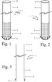
- the invention is comprised of a self-fixing prosthesis and an instrument for creating an end-to-side anastomosis with the prosthesis. Schematic illustrations of the invention are shown in Figs. 1-3 .
- the prosthesis is a tubular member 1 with a leading end 2 limited by a leading edge 3, and a trailing end 4 limited by a trailing edge 5.
- leading identifies the end or edge of an object, such as a prosthesis or device, that precedes the rest of said object, when said object is being introduced into another object such as the human body.
- directionally describing expressions “leading” and “trailing” are herein used in the context of the direction of attachment of the tubular member to an organ, such as a blood vessel.
- the leading end is the end that is first inserted to the body and organ.
- the leading end 2 of the prosthesis is radially compressible.
- the leading edge 3 of the prosthesis is provided with one or more flexible anchoring members 6 ("radial anchors").
- the radial anchors 6 are initially directed outwards, in relation to the longitudinal direction of the tubular member 1, and towards the trailing end 5 of the prosthesis. In other words, the radial anchors 6 are initially arranged at an acute angle on the outside of the tubular member 1, and generally pointing in the direction of the trailing end rather that in the direction of insertion. The insertion procedure will be described in more detail below.
- the leading end 2 is elliptical in cross-section perpendicular to the longitudinal axis of the prosthesis, and the plane defined by the leading edge 3 is not perpendicular to the longitudinal axis of the prosthesis (as seen for example in Fig. 4 ).
- the leading end 2 is oval in cross-section perpendicular to the longitudinal axis of the prosthesis.
- the leading end 2 is circular in cross-section perpendicular to the longitudinal axis of the prosthesis.
- the leading end 2 is non-circular in cross-section perpendicular to the longitudinal axis of the prosthesis.
- the plane defined by the leading edge 3 is perpendicular to the longitudinal axis of the prosthesis.
- the leading end 2 is radially compressible and plastic, i.e. has plastic characteristics. On application of centripetal radial force of appropriate magnitude, the leading end 2 will be radially compressed. On removal of the centripetal force, the leading end 2 remains essentially unchanged in size. The compressed leading end 2 can be expanded to its nominal radial size by the intraluminal application of centrifugal force of appropriate magnitude. In an alternative embodiment of the prosthesis, the leading end 2 is radially resilient. On application of centripetal radial force of appropriate magnitude, the leading end 2 gets radially compressed. On removal of the centripetal force, the leading end 2 expands spontaneously to its nominal radial size.
- the radial anchors 6 are preferably two or more arranged equally around the circumference of the leading edge 3.
- Each individual radial anchor can be provided as an essentially round wire or as strips cut from a tubular member.
- the radial anchors 6 are structurally continuous with the leading edge 3 of the prosthesis.
- One example of such an arrangement is providing a lasercut tubular member with protruding anchoring members cut from the end of the tubular device.
- the radial anchors 6 are attached to the leading edge 3 of the prosthesis.
- the leading end 2 of the prosthesis is provided with a reversibly compressible, snugly fitting collar ("anchor collar") 7, with a leading edge 9 and a trailing edge 8.
- anchor collar a reversibly compressible, snugly fitting collar
- the leading edge 9 of the anchor collar 7 is flush with the leading edge 2 of the prosthesis ( Fig. 5a ).
- the radial anchors 6 are structurally continuous with the leading edge 9 of the anchor collar 7.
- the radial anchors 6 are attached to the leading edge 9 of the anchor collar 7.
- the leading edge 9 of the anchor collar 7 is not flush with the leading edge 3 of the prosthesis, such that the prosthesis protrudes slightly through the anchor collar 7 ( Fig. 5b ).
- the leading end 2 is provided with an external coaxial expandable ring ("sealing ring") (10).
- the sealing ring is plastic.
- the sealing ring 10 is radially compressible and plastic.
- the sealing ring 10 is elastic.
- the sealing ring 10 stimulates clotting of blood.
- the sealing ring 10 is made of, or is coated with a material that increases in volume on exposure to fluids such as for example hydrogels.
- the sealing ring 10 encircles the radial anchors 6 ( Fig 6a ).
- the sealing ring 10 is larger than the compressed prosthesis in cross-section ( Fig. 6b ), such that it is not held to the prosthesis by friction, but is prevented from moving to the leading end 2 of the prosthesis by the radial anchors 6.
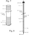
- the trailing end 4 is radially compressible and plastic ( Fig. 7 ). In an alternative embodiment of the prosthesis, the trailing end 4 is radially resilient.
- first deployment instrument is comprised of a tubular member 12 (deployment catheter) and a coaxial linear flexible member 13 (needle wire).
- the deployment catheter 12 has a leading end 14 limited by a leading edge 15, a shaft 16 and a trailing end 17.
- the trailing end 17 of the deployment catheter 12 is provided with a means 18 for reversibly securing the needle wire 13, such as a Tuohy-Borst valve.
- the leading end of the deployment catheter 12 is radially expandable.
- the shaft 16 of the deployment catheter 12 is provided with a means to expand the leading end 14.
- the needle wire 13 has a leading end 19 limited by a leading tip 20 and a shaft 21, and can be moved along the longitudinal axis of the deployment catheter 12.
- the leading end 19 is more flexible than the shaft 21.
- the leading tip 20 of the needle wire 13 is shaped such that it can perforate an organ, such as a blood vessel.
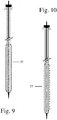
- the leading end 14 of the deployment catheter 12 is provided with a balloon 22 ("balloon deployment catheter") ( Fig. 9 ).
- the shaft 16 of the deployment catheter is provided with a channel that allows the balloon 22 to be inflated.
- the leading end 14 of the deployment catheter 12 is provided with an expandable basket like structure 23 (basket deployment catheter) ( Fig. 10 ).
- the shaft 16 is provided with means to expand the basket.
- the deployment catheter 12 is partially enclosed within a coaxial tubular member 24 ("inner sheath"), with a leading end 25 and a trailing end 26.
- the inner sheath 24 is encircled at its leading end by a sealing ring 10.
- the sealing ring 10 is dimensionally matched to the inner sheath 24, such that the it is held in position on the sheath 24 by friction, but is movable along the long axis of the of the inner sheath 24.
- the inner sheath 24 is partially enclosed within a second coaxial member 27 (pusher), such that the sealing ring 10 can be moved to the leading end 25 of the inner sheath with the pusher 27.
- One embodiment of the instrument for performing an anastomosis with the prosthesis 31 (second deployment instrument) ( Fig, 12 ) is comprised of a first tubular member 32 ("carrier catheter"), a coaxial second tubular member 33 (“protective sheath”) that partially encloses the first tubular member 32 and a needle wire 13.
- the carrier catheter 32 has a leading end 34 limited by a leading edge 35, a shaft 36 and a trailing end 37.
- the trailing end 37 of the carrier catheter 32 is provided with a means 38 for reversibly securing the shaft of the needle wire 13, such as a Tuohy-Borst valve.
- the protective sheath 33 has a leading end 39 limited by a leading edge 40, a shaft 41 and a trailing end 42. The sheath 33 can accommodate the prosthesis, when the prosthesis is mounted on the carrier catheter 32.
- the protective sheath 33 is provided with a sealing ring 10 at its leading end 39.
- the ring 13 is dimensionally matched to the protective sheath 33, such that it is held in position by friction, but is nonetheless movable along the long axis of the protective sheath 33.
- the protective sheath 33 is partially enclosed within a coaxial tubular member 43 ("pusher"), with a leading end 44 and a trailing end 45, such that the sealing ring 13 can be moved to the leading end 39 of the protective sheath 33 with the pusher 43.
- the instrument for deploying the prosthesis is provided with a deployment guide 46 comprised of a first tubular member 47 (guide sheath), a coaxial second tubular member 48 that is partially enclosed within the first tubular member (guide pusher), and a sealing ring 13 that is completely enclosed within the first tubular member 47.
- the guide sheath has a leading end 49 limited by a leading edge 50, and a trailing end 51.
- the guide pusher 48 has a leading end 52 limited by a leading edge 53, and a trailing end 54, and can accommodate the instrument for deploying the prosthesis.
- the sealing ring 10 is dimensionally matched to the lumen of the guide sheath 47, such that it is held in place within the guide sheath 47 by friction, but can be moved towards the leading end 49 of the guide sheath 47 with the guide pusher 48.
- the sealing ring 10 can accommodate the instrument for deploying the prosthesis.
- the leading end 19 of the needle wire 21 describes a curve when it is not constrained ( Fig. 15 ).
- the needle wire is hollow along its entire length.
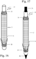
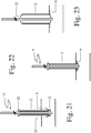
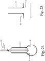
- Figs. 17-25 illustrate performance of the anastomosis with a radially compressible, plastic prosthesis using a deployment instrument incorporating a balloon deployment catheter 22.
- the site for anastomosis is selected after visual inspection, or ultrasonographic examination of e.g. an aorta 55.
- the needle wire 21 is advanced through the deployment balloon catheter 22. Once the leading tip 20 protrudes through the catheter 22, the needle wire 21 is secured to the trailing end of the catheter 22.
- the catheter and needle wire are introduced into the aorta.
- the needle wire 21 is released from the trailing end of the catheter 22 and advanced till its shaft 21 has entered the aorta 55 ( Fig. 19 ).
- the deployment catheter is advanced until all the radial anchors 6 are inside the aorta ( Fig. 20 ).
- the balloon is partially expanded, as shown in Figure 21 .
- the balloon deployment catheter 22 and prosthesis are slowly withdrawn, until resistance is felt, indicating that the radial anchors 6 and the leading edge 3 of the prosthesis are substantially flush with the luminal surface of the aorta 55 ( Fig. 22 ).
- the balloon is inflated to its nominal diameter expanding the prosthesis.
- Figure 23 shows the inflated balloon in a view along a longitudinal cross-section of the aorta
- Figure 24 shows how the same step from a view perpendicular to a longitudinal axis of the aorta.
- the balloon is thereafter deflated, and the balloon deployment catheter is removed ( Fig. 25 ).
- Tissue adhesive is applied at the junction of the artery and the prosthesis to reinforce the anastomosis if desired.
- the arrangement of the radial anchors 6 being initially arranged at an acute angle pointing back towards the trailing end, as can be seen in the figures, has the advantage of facilitating entry of the deployment assembly into the organ of choice.
- the radial anchors 6 are bent to an angle essentially perpendicular to the longitudinal axis of the tubular member, as can be seen in e.g. Fig. 22 , such that the radial anchors 6 are flush against the inner organ wall. This ensures satisfactory anchoring of the tubular device, yet ensures that only very little non-endothelial surface is exposed to blood
- At least the leading end of the tubular device is reversibly radially compressible. This ensures easy deployment and secure anchoring of the tubular device. This allows the anastomosis to be performed through a puncture in the wall of an artery in contrast to the incision required with devices described thus far.
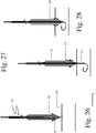
- Figs. 26-32 illustrate how performance of the anastomosis with a radially compressible, plastic prosthesis incorporating a sealing ring 10 differs from the procedure described above.
- the sealing ring 10 is retained on the aortic wall ( Fig. 28 ).
- the ring is held in place when deployment catheter 15 and the prosthesis are withdrawn.
- the seal is then released.
- the balloon is inflated, the sealing ring is expanded securing it to the prosthesis, thereby sealing the anastomosis ( Fig. 32 ). If the non-expanded sealing ring is larger than the compressed prosthesis in cross-section, the seal need not be held in place.
- the sealing ring is not secured to the prosthesis by friction, it remains in place at the anastomosis site when the deployment catheter 15 and the prosthesis are withdrawn.
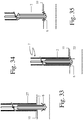
- Figs. 33-35 illustrate how performance of the anastomosis with a radially compressible, plastic prosthesis and a deployment instrument incorporating a sealing ring differs from the procedure described above.
- the inner sheath 24 is withdrawn out of the aorta 55, exposing the radial anchors (6).
- the pusher 27 is advanced to the sealing ring 10 to retain it at the anastomosis ( Fig. 33 ).
- the deployment catheter and prosthesis are withdrawn until the radial anchors 6 are flush with the luminal surface of the aorta 55 ( Fig. 34 ).
- the inner sheath 24 is then withdrawn until the entire prosthesis is outside the sheath.
- the pusher 27 is then withdrawn until it no longer encloses the prosthesis ( Fig. 35 ).
- the prosthesis is expanded as described above, securing the sealing collar to the anastomosis.
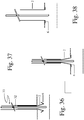
- Figs. 36-38 illustrate how performance of the anastomosis with a radially compressible, radially resilient prosthesis and a second deployment instrument differs from the procedures described above.
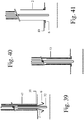
- Figs. 39-41 illustrate how performance of the anastomosis with a radially compressible, radially resilient prosthesis and sealing ring incorporated in deployment instrument differs from the procedure described above.
- An alternative way of performing an anastomosis with the prosthesis is as follows.
- the site for anastomosis is selected after visual inspection, or ultrasonographic examination of the aorta.
- a sealing ring is placed at the site and held in place.
- a compressible plastic or a compressible resilient prosthesis is then deployed as described above.
Landscapes
- Health & Medical Sciences (AREA)
- Life Sciences & Earth Sciences (AREA)
- Engineering & Computer Science (AREA)
- Biomedical Technology (AREA)
- General Health & Medical Sciences (AREA)
- Public Health (AREA)
- Heart & Thoracic Surgery (AREA)
- Veterinary Medicine (AREA)
- Animal Behavior & Ethology (AREA)
- Surgery (AREA)
- Transplantation (AREA)
- Cardiology (AREA)
- Oral & Maxillofacial Surgery (AREA)
- Vascular Medicine (AREA)
- Nuclear Medicine, Radiotherapy & Molecular Imaging (AREA)
- Molecular Biology (AREA)
- Medical Informatics (AREA)
- Gastroenterology & Hepatology (AREA)
- Pulmonology (AREA)
- Prostheses (AREA)
- Materials For Medical Uses (AREA)
Claims (10)
- Anastomosenprothese zur Ende-zu-Seite-Verbindung eines Gefäßimplantats mit einem Blutgefäß, wobei die Prothese ein röhrenförmiges Element (1) mit einem vorderen Ende (2), das eine vordere Kante (3) umfasst, und einem hinteren Ende (4) umfasst, das eine hintere Kante (5) umfasst, wobei
das vordere Ende (2) des röhrenförmigen Elements (1) umkehrbar radial komprimierbar ist, und
die vordere Kante (3) des röhrenförmigen Elements (1) mit einem oder mehreren radial nach außen gerichteten flexiblen linearen Ankerelementen (6) bereitgestellt ist, wobei die Ankerelemente (6) anfänglich in einem Winkel in Bezug auf eine Längsachse des röhrenförmigen Elements (1) und derart angeordnet sind, dass die Ankerelemente (6) in die Richtung des hinteren Endes des röhrenförmigen Elements zeigen,
dadurch gekennzeichnet, dass
das vordere Ende des röhrenförmigen Elements (1) mit einem koaxialen äußeren ausdehnbaren Ring (10) bereitgestellt ist, wobei der Ring (10) mit der vorderen Kante des röhrenförmigen Elements (1) bündig ist und der Ring (10) die Ankerelemente (6) umgibt. - Anastomosenprothese nach Anspruch 1, wobei das vordere Ende des röhrenförmigen Elements nicht kreisförmig im Querschnitt senkrecht zu der Längsachse des röhrenförmigen Elements ist.
- Anastomosenprothese nach Anspruch 1, wobei die Ebene, die durch die vordere Kante des röhrenförmigen Elements (1) definiert ist, nicht senkrecht zu der Längsachse des röhrenförmigen Elements ist.
- Anastomosenprothese nach Anspruch 1, wobei das vordere Ende derart aus Kunststoff ist, dass das vordere Ende zu seiner nominalen radialen Größe durch Aussetzen gegenüber einer Zentrifugalkraft ausgedehnt werden kann.
- Anastomosenprothese nach Anspruch 1, wobei das vordere Ende derart radial elastisch ist, dass das vordere Ende sich spontan auf seine nominale (uneingeschränkte) radiale Größe ausdehnt, wenn es nicht länger radial eingeschränkt wird.
- Anastomosenprothese nach Anspruch 1, wobei das vordere Ende derart aus Kunststoff ist, dass sich das vordere Ende auf seine nominale (uneingeschränkte) Größe ausdehnt, wenn die lokale thermische Umgebung dementsprechend verändert wird.
- Anastomosenprothese nach Anspruch 1, wobei das vordere Ende des röhrenförmigen Elements mit einer passgenauen externen Manschette mit einen vorderen Ende, das durch eine vordere Kante begrenzt ist, bereitgestellt ist, wobei die vordere Kante des röhrenförmigen Elements mit der vorderen Kante der externen Manschette bündig ist und die nach außen gerichteten Elemente fortlaufend mit der vorderen Kante der externen Manschette sind.
- Anastomosenprothese nach Anspruch 1, wobei das vordere Ende des röhrenförmigen Elements mit einer passgenauen externen Manschette mit einen vorderen Ende, das durch eine vordere Kante begrenzt ist, bereitgestellt ist, wobei die vordere Kante des röhrenförmigen Elements mit der vorderen Kante der externen Manschette bündig ist und die nach außen gerichteten Elemente an der vorderen Kante der externen Manschette angebracht sind.
- Anastomosenprothese nach Anspruch 1, wobei die äußere Fläche des hinteren Endes des röhrenförmigen Elements nicht glatt ist.
- Anastomosenprothese nach Anspruch 1, wobei das hintere Ende des röhrenförmigen Elements umkehrbar radial komprimierbar ist.
Applications Claiming Priority (2)
| Application Number | Priority Date | Filing Date | Title |
|---|---|---|---|
| US201462036345P | 2014-08-12 | 2014-08-12 | |
| PCT/EP2015/068474 WO2016023907A2 (en) | 2014-08-12 | 2015-08-11 | Minimally traumatic anastomosis |
Publications (2)
| Publication Number | Publication Date |
|---|---|
| EP3179925A2 EP3179925A2 (de) | 2017-06-21 |
| EP3179925B1 true EP3179925B1 (de) | 2019-06-19 |
Family
ID=53800994
Family Applications (1)
| Application Number | Title | Priority Date | Filing Date |
|---|---|---|---|
| EP15748251.4A Active EP3179925B1 (de) | 2014-08-12 | 2015-08-11 | Minimal traumatische anastomose |
Country Status (6)
| Country | Link |
|---|---|
| US (1) | US10631864B2 (de) |
| EP (1) | EP3179925B1 (de) |
| JP (1) | JP6660938B2 (de) |
| CA (1) | CA2955338C (de) |
| ES (1) | ES2745336T3 (de) |
| WO (1) | WO2016023907A2 (de) |
Family Cites Families (19)
| Publication number | Priority date | Publication date | Assignee | Title |
|---|---|---|---|---|
| CA2125258C (en) * | 1993-08-05 | 1998-12-22 | Dinah B Quiachon | Multicapsule intraluminal grafting system and method |
| US5695504A (en) * | 1995-02-24 | 1997-12-09 | Heartport, Inc. | Devices and methods for performing a vascular anastomosis |
| US5755778A (en) | 1996-10-16 | 1998-05-26 | Nitinol Medical Technologies, Inc. | Anastomosis device |
| EP0951252A2 (de) * | 1996-11-07 | 1999-10-27 | Vascular Science Inc. | Midizinische transplantatverfahren sowie vorrichtung |
| WO1999051165A1 (en) * | 1998-04-02 | 1999-10-14 | Salviac Limited | An implant comprising a support structure and a transition material made of porous plastics material |
| US7063711B1 (en) * | 1998-05-29 | 2006-06-20 | By-Pass, Inc. | Vascular surgery |
| CA2366703A1 (en) | 1999-03-19 | 2000-09-28 | By-Pass, Inc. | Vascular surgery |
| US6241743B1 (en) | 1999-05-13 | 2001-06-05 | Intellicardia, Inc. | Anastomosis device and method |
| ATE301426T1 (de) | 1999-10-08 | 2005-08-15 | Gen Hospital Corp | Perkutane stentprothese |
| US6746459B2 (en) * | 2000-10-19 | 2004-06-08 | Terumo Kabushiki Kaisha | End-to-side blood vessel anastomosis method and instruments therefor |
| US6767359B2 (en) | 2001-09-28 | 2004-07-27 | Ethicon, Inc. | Prosthesis for the repair of thoracic or abdominal aortic aneurysms and method therefor |
| US7361181B2 (en) | 2002-10-04 | 2008-04-22 | St. Jude Medical Atg, Inc. | Apparatus and methods for creating anastomoses |
| US9333102B2 (en) * | 2003-02-24 | 2016-05-10 | Allium Medical Solutions Ltd. | Stent |
| WO2007029989A1 (en) * | 2005-09-09 | 2007-03-15 | Hbmedicals Co., Ltd. | Tube-shaped vascular anastomosis devices and method of using thereof |
| DE102008055587B4 (de) | 2008-02-14 | 2017-04-06 | Adolf Picek | Steckprothese in Variationsnotwendigkeiten zur Schnellanastomosierung von Blutgefäßen und anderen relativ weichen röhrenartigen Organen |
| US7920339B2 (en) * | 2008-07-02 | 2011-04-05 | Aptina Imaging Corporation | Method and apparatus providing singlet wafer lens system with field flattener |
| US9820746B2 (en) * | 2008-07-28 | 2017-11-21 | Incube Laboratories LLC | System and method for scaffolding anastomoses |
| JP4815024B1 (ja) * | 2010-07-02 | 2011-11-16 | 日機装株式会社 | 人工血管および人工血管のアクセスポート |
| WO2012117402A1 (en) * | 2011-03-01 | 2012-09-07 | Seamvad Ltd. | Anastomosis device |
-
2015
- 2015-08-11 EP EP15748251.4A patent/EP3179925B1/de active Active
- 2015-08-11 ES ES15748251T patent/ES2745336T3/es active Active
- 2015-08-11 CA CA2955338A patent/CA2955338C/en active Active
- 2015-08-11 JP JP2017506961A patent/JP6660938B2/ja active Active
- 2015-08-11 WO PCT/EP2015/068474 patent/WO2016023907A2/en not_active Ceased
- 2015-08-11 US US15/502,375 patent/US10631864B2/en active Active
Non-Patent Citations (1)
| Title |
|---|
| None * |
Also Published As
| Publication number | Publication date |
|---|---|
| CA2955338A1 (en) | 2016-02-18 |
| ES2745336T3 (es) | 2020-02-28 |
| WO2016023907A2 (en) | 2016-02-18 |
| WO2016023907A3 (en) | 2016-04-07 |
| JP6660938B2 (ja) | 2020-03-11 |
| US10631864B2 (en) | 2020-04-28 |
| JP2017524479A (ja) | 2017-08-31 |
| CA2955338C (en) | 2022-06-21 |
| US20170231634A1 (en) | 2017-08-17 |
| EP3179925A2 (de) | 2017-06-21 |
Similar Documents
| Publication | Publication Date | Title |
|---|---|---|
| US6533812B2 (en) | Medical anastomosis apparatus | |
| US5755775A (en) | Percutaneous stent-graft and method for delivery thereof | |
| JP4767292B2 (ja) | 中隔欠損を閉じる際に使用するためのデバイス | |
| US7648515B2 (en) | Method and apparatus for anastomosis including an expandable anchor | |
| US6599302B2 (en) | Aortic aneurysm treatment systems | |
| US6743243B1 (en) | Support device for endoscopic suturless anastomosis | |
| US6241741B1 (en) | Anastomosis device and method | |
| JP2004528120A (ja) | 医療移植の方法および装置 | |
| US11413043B2 (en) | Anchor device for vascular anastomosis | |
| WO2011060249A2 (en) | Methods and apparatus for vascular anastomosis | |
| US12201298B2 (en) | Anastomotic coupler | |
| JP7182797B2 (ja) | 外科的血管吻合術に使用する装置および方法 | |
| US12035899B2 (en) | Medical apparatus and method for closing an opening in a tissue | |
| US8357173B2 (en) | Anastomosis device | |
| US10631864B2 (en) | Minimally traumatic anastomosis | |
| US20040186548A1 (en) | Device for anastomosing anatomical ducts | |
| JP7660701B2 (ja) | 動静脈グラフトをインプラント処置するための装置及び方法 | |
| IL135368A (en) | Device for performing a quick anastomosis in blood vessels or other biological tubes |
Legal Events
| Date | Code | Title | Description |
|---|---|---|---|
| STAA | Information on the status of an ep patent application or granted ep patent |
Free format text: STATUS: THE INTERNATIONAL PUBLICATION HAS BEEN MADE |
|
| PUAI | Public reference made under article 153(3) epc to a published international application that has entered the european phase |
Free format text: ORIGINAL CODE: 0009012 |
|
| STAA | Information on the status of an ep patent application or granted ep patent |
Free format text: STATUS: REQUEST FOR EXAMINATION WAS MADE |
|
| 17P | Request for examination filed |
Effective date: 20170307 |
|
| AK | Designated contracting states |
Kind code of ref document: A2 Designated state(s): AL AT BE BG CH CY CZ DE DK EE ES FI FR GB GR HR HU IE IS IT LI LT LU LV MC MK MT NL NO PL PT RO RS SE SI SK SM TR |
|
| AX | Request for extension of the european patent |
Extension state: BA ME |
|
| DAV | Request for validation of the european patent (deleted) | ||
| DAX | Request for extension of the european patent (deleted) | ||
| STAA | Information on the status of an ep patent application or granted ep patent |
Free format text: STATUS: EXAMINATION IS IN PROGRESS |
|
| 17Q | First examination report despatched |
Effective date: 20171220 |
|
| GRAP | Despatch of communication of intention to grant a patent |
Free format text: ORIGINAL CODE: EPIDOSNIGR1 |
|
| STAA | Information on the status of an ep patent application or granted ep patent |
Free format text: STATUS: GRANT OF PATENT IS INTENDED |
|
| GRAJ | Information related to disapproval of communication of intention to grant by the applicant or resumption of examination proceedings by the epo deleted |
Free format text: ORIGINAL CODE: EPIDOSDIGR1 |
|
| STAA | Information on the status of an ep patent application or granted ep patent |
Free format text: STATUS: EXAMINATION IS IN PROGRESS |
|
| GRAP | Despatch of communication of intention to grant a patent |
Free format text: ORIGINAL CODE: EPIDOSNIGR1 |
|
| STAA | Information on the status of an ep patent application or granted ep patent |
Free format text: STATUS: GRANT OF PATENT IS INTENDED |
|
| INTG | Intention to grant announced |
Effective date: 20190311 |
|
| INTC | Intention to grant announced (deleted) | ||
| INTG | Intention to grant announced |
Effective date: 20190410 |
|
| GRAS | Grant fee paid |
Free format text: ORIGINAL CODE: EPIDOSNIGR3 |
|
| GRAA | (expected) grant |
Free format text: ORIGINAL CODE: 0009210 |
|
| STAA | Information on the status of an ep patent application or granted ep patent |
Free format text: STATUS: THE PATENT HAS BEEN GRANTED |
|
| AK | Designated contracting states |
Kind code of ref document: B1 Designated state(s): AL AT BE BG CH CY CZ DE DK EE ES FI FR GB GR HR HU IE IS IT LI LT LU LV MC MK MT NL NO PL PT RO RS SE SI SK SM TR |
|
| REG | Reference to a national code |
Ref country code: GB Ref legal event code: FG4D |
|
| REG | Reference to a national code |
Ref country code: CH Ref legal event code: EP |
|
| REG | Reference to a national code |
Ref country code: IE Ref legal event code: FG4D |
|
| REG | Reference to a national code |
Ref country code: DE Ref legal event code: R096 Ref document number: 602015032289 Country of ref document: DE |
|
| REG | Reference to a national code |
Ref country code: AT Ref legal event code: REF Ref document number: 1144490 Country of ref document: AT Kind code of ref document: T Effective date: 20190715 |
|
| REG | Reference to a national code |
Ref country code: NL Ref legal event code: FP |
|
| PG25 | Lapsed in a contracting state [announced via postgrant information from national office to epo] |
Ref country code: AL Free format text: LAPSE BECAUSE OF FAILURE TO SUBMIT A TRANSLATION OF THE DESCRIPTION OR TO PAY THE FEE WITHIN THE PRESCRIBED TIME-LIMIT Effective date: 20190619 Ref country code: SE Free format text: LAPSE BECAUSE OF FAILURE TO SUBMIT A TRANSLATION OF THE DESCRIPTION OR TO PAY THE FEE WITHIN THE PRESCRIBED TIME-LIMIT Effective date: 20190619 Ref country code: FI Free format text: LAPSE BECAUSE OF FAILURE TO SUBMIT A TRANSLATION OF THE DESCRIPTION OR TO PAY THE FEE WITHIN THE PRESCRIBED TIME-LIMIT Effective date: 20190619 Ref country code: NO Free format text: LAPSE BECAUSE OF FAILURE TO SUBMIT A TRANSLATION OF THE DESCRIPTION OR TO PAY THE FEE WITHIN THE PRESCRIBED TIME-LIMIT Effective date: 20190919 Ref country code: LT Free format text: LAPSE BECAUSE OF FAILURE TO SUBMIT A TRANSLATION OF THE DESCRIPTION OR TO PAY THE FEE WITHIN THE PRESCRIBED TIME-LIMIT Effective date: 20190619 Ref country code: HR Free format text: LAPSE BECAUSE OF FAILURE TO SUBMIT A TRANSLATION OF THE DESCRIPTION OR TO PAY THE FEE WITHIN THE PRESCRIBED TIME-LIMIT Effective date: 20190619 |
|
| REG | Reference to a national code |
Ref country code: LT Ref legal event code: MG4D |
|
| PG25 | Lapsed in a contracting state [announced via postgrant information from national office to epo] |
Ref country code: BG Free format text: LAPSE BECAUSE OF FAILURE TO SUBMIT A TRANSLATION OF THE DESCRIPTION OR TO PAY THE FEE WITHIN THE PRESCRIBED TIME-LIMIT Effective date: 20190919 Ref country code: GR Free format text: LAPSE BECAUSE OF FAILURE TO SUBMIT A TRANSLATION OF THE DESCRIPTION OR TO PAY THE FEE WITHIN THE PRESCRIBED TIME-LIMIT Effective date: 20190920 Ref country code: LV Free format text: LAPSE BECAUSE OF FAILURE TO SUBMIT A TRANSLATION OF THE DESCRIPTION OR TO PAY THE FEE WITHIN THE PRESCRIBED TIME-LIMIT Effective date: 20190619 Ref country code: RS Free format text: LAPSE BECAUSE OF FAILURE TO SUBMIT A TRANSLATION OF THE DESCRIPTION OR TO PAY THE FEE WITHIN THE PRESCRIBED TIME-LIMIT Effective date: 20190619 |
|
| REG | Reference to a national code |
Ref country code: AT Ref legal event code: MK05 Ref document number: 1144490 Country of ref document: AT Kind code of ref document: T Effective date: 20190619 |
|
| PG25 | Lapsed in a contracting state [announced via postgrant information from national office to epo] |
Ref country code: AT Free format text: LAPSE BECAUSE OF FAILURE TO SUBMIT A TRANSLATION OF THE DESCRIPTION OR TO PAY THE FEE WITHIN THE PRESCRIBED TIME-LIMIT Effective date: 20190619 Ref country code: PT Free format text: LAPSE BECAUSE OF FAILURE TO SUBMIT A TRANSLATION OF THE DESCRIPTION OR TO PAY THE FEE WITHIN THE PRESCRIBED TIME-LIMIT Effective date: 20191021 Ref country code: EE Free format text: LAPSE BECAUSE OF FAILURE TO SUBMIT A TRANSLATION OF THE DESCRIPTION OR TO PAY THE FEE WITHIN THE PRESCRIBED TIME-LIMIT Effective date: 20190619 Ref country code: RO Free format text: LAPSE BECAUSE OF FAILURE TO SUBMIT A TRANSLATION OF THE DESCRIPTION OR TO PAY THE FEE WITHIN THE PRESCRIBED TIME-LIMIT Effective date: 20190619 Ref country code: CZ Free format text: LAPSE BECAUSE OF FAILURE TO SUBMIT A TRANSLATION OF THE DESCRIPTION OR TO PAY THE FEE WITHIN THE PRESCRIBED TIME-LIMIT Effective date: 20190619 Ref country code: SK Free format text: LAPSE BECAUSE OF FAILURE TO SUBMIT A TRANSLATION OF THE DESCRIPTION OR TO PAY THE FEE WITHIN THE PRESCRIBED TIME-LIMIT Effective date: 20190619 |
|
| PG25 | Lapsed in a contracting state [announced via postgrant information from national office to epo] |
Ref country code: SM Free format text: LAPSE BECAUSE OF FAILURE TO SUBMIT A TRANSLATION OF THE DESCRIPTION OR TO PAY THE FEE WITHIN THE PRESCRIBED TIME-LIMIT Effective date: 20190619 Ref country code: IS Free format text: LAPSE BECAUSE OF FAILURE TO SUBMIT A TRANSLATION OF THE DESCRIPTION OR TO PAY THE FEE WITHIN THE PRESCRIBED TIME-LIMIT Effective date: 20191019 |
|
| REG | Reference to a national code |
Ref country code: ES Ref legal event code: FG2A Ref document number: 2745336 Country of ref document: ES Kind code of ref document: T3 Effective date: 20200228 |
|
| PG25 | Lapsed in a contracting state [announced via postgrant information from national office to epo] |
Ref country code: TR Free format text: LAPSE BECAUSE OF FAILURE TO SUBMIT A TRANSLATION OF THE DESCRIPTION OR TO PAY THE FEE WITHIN THE PRESCRIBED TIME-LIMIT Effective date: 20190619 |
|
| PG25 | Lapsed in a contracting state [announced via postgrant information from national office to epo] |
Ref country code: DK Free format text: LAPSE BECAUSE OF FAILURE TO SUBMIT A TRANSLATION OF THE DESCRIPTION OR TO PAY THE FEE WITHIN THE PRESCRIBED TIME-LIMIT Effective date: 20190619 Ref country code: PL Free format text: LAPSE BECAUSE OF FAILURE TO SUBMIT A TRANSLATION OF THE DESCRIPTION OR TO PAY THE FEE WITHIN THE PRESCRIBED TIME-LIMIT Effective date: 20190619 |
|
| PG25 | Lapsed in a contracting state [announced via postgrant information from national office to epo] |
Ref country code: LU Free format text: LAPSE BECAUSE OF NON-PAYMENT OF DUE FEES Effective date: 20190811 Ref country code: LI Free format text: LAPSE BECAUSE OF NON-PAYMENT OF DUE FEES Effective date: 20190831 Ref country code: IS Free format text: LAPSE BECAUSE OF FAILURE TO SUBMIT A TRANSLATION OF THE DESCRIPTION OR TO PAY THE FEE WITHIN THE PRESCRIBED TIME-LIMIT Effective date: 20200224 Ref country code: MC Free format text: LAPSE BECAUSE OF FAILURE TO SUBMIT A TRANSLATION OF THE DESCRIPTION OR TO PAY THE FEE WITHIN THE PRESCRIBED TIME-LIMIT Effective date: 20190619 Ref country code: CH Free format text: LAPSE BECAUSE OF NON-PAYMENT OF DUE FEES Effective date: 20190831 |
|
| REG | Reference to a national code |
Ref country code: BE Ref legal event code: MM Effective date: 20190831 |
|
| REG | Reference to a national code |
Ref country code: DE Ref legal event code: R097 Ref document number: 602015032289 Country of ref document: DE |
|
| PLBE | No opposition filed within time limit |
Free format text: ORIGINAL CODE: 0009261 |
|
| STAA | Information on the status of an ep patent application or granted ep patent |
Free format text: STATUS: NO OPPOSITION FILED WITHIN TIME LIMIT |
|
| PG2D | Information on lapse in contracting state deleted |
Ref country code: IS |
|
| PG25 | Lapsed in a contracting state [announced via postgrant information from national office to epo] |
Ref country code: IE Free format text: LAPSE BECAUSE OF NON-PAYMENT OF DUE FEES Effective date: 20190811 |
|
| 26N | No opposition filed |
Effective date: 20200603 |
|
| PG25 | Lapsed in a contracting state [announced via postgrant information from national office to epo] |
Ref country code: SI Free format text: LAPSE BECAUSE OF FAILURE TO SUBMIT A TRANSLATION OF THE DESCRIPTION OR TO PAY THE FEE WITHIN THE PRESCRIBED TIME-LIMIT Effective date: 20190619 Ref country code: BE Free format text: LAPSE BECAUSE OF NON-PAYMENT OF DUE FEES Effective date: 20190831 |
|
| PG25 | Lapsed in a contracting state [announced via postgrant information from national office to epo] |
Ref country code: CY Free format text: LAPSE BECAUSE OF FAILURE TO SUBMIT A TRANSLATION OF THE DESCRIPTION OR TO PAY THE FEE WITHIN THE PRESCRIBED TIME-LIMIT Effective date: 20190619 |
|
| PG25 | Lapsed in a contracting state [announced via postgrant information from national office to epo] |
Ref country code: HU Free format text: LAPSE BECAUSE OF FAILURE TO SUBMIT A TRANSLATION OF THE DESCRIPTION OR TO PAY THE FEE WITHIN THE PRESCRIBED TIME-LIMIT; INVALID AB INITIO Effective date: 20150811 Ref country code: MT Free format text: LAPSE BECAUSE OF FAILURE TO SUBMIT A TRANSLATION OF THE DESCRIPTION OR TO PAY THE FEE WITHIN THE PRESCRIBED TIME-LIMIT Effective date: 20190619 |
|
| PG25 | Lapsed in a contracting state [announced via postgrant information from national office to epo] |
Ref country code: MK Free format text: LAPSE BECAUSE OF FAILURE TO SUBMIT A TRANSLATION OF THE DESCRIPTION OR TO PAY THE FEE WITHIN THE PRESCRIBED TIME-LIMIT Effective date: 20190619 |
|
| PGFP | Annual fee paid to national office [announced via postgrant information from national office to epo] |
Ref country code: NL Payment date: 20250818 Year of fee payment: 11 |
|
| PGFP | Annual fee paid to national office [announced via postgrant information from national office to epo] |
Ref country code: ES Payment date: 20250910 Year of fee payment: 11 |
|
| PGFP | Annual fee paid to national office [announced via postgrant information from national office to epo] |
Ref country code: DE Payment date: 20250819 Year of fee payment: 11 |
|
| PGFP | Annual fee paid to national office [announced via postgrant information from national office to epo] |
Ref country code: IT Payment date: 20250821 Year of fee payment: 11 |
|
| PGFP | Annual fee paid to national office [announced via postgrant information from national office to epo] |
Ref country code: GB Payment date: 20250819 Year of fee payment: 11 |
|
| PGFP | Annual fee paid to national office [announced via postgrant information from national office to epo] |
Ref country code: FR Payment date: 20250818 Year of fee payment: 11 |