EP3179341B1 - Verfahren und vorrichtung zur messung des drucks auf einem bildschirm mit mindestens einem sensor - Google Patents
Verfahren und vorrichtung zur messung des drucks auf einem bildschirm mit mindestens einem sensor Download PDFInfo
- Publication number
- EP3179341B1 EP3179341B1 EP15199481.1A EP15199481A EP3179341B1 EP 3179341 B1 EP3179341 B1 EP 3179341B1 EP 15199481 A EP15199481 A EP 15199481A EP 3179341 B1 EP3179341 B1 EP 3179341B1
- Authority
- EP
- European Patent Office
- Prior art keywords
- pressure
- screen
- location
- sensor means
- value
- Prior art date
- Legal status (The legal status is an assumption and is not a legal conclusion. Google has not performed a legal analysis and makes no representation as to the accuracy of the status listed.)
- Active
Links
- 238000000034 method Methods 0.000 title claims description 17
- 238000012937 correction Methods 0.000 claims description 36
- 239000011159 matrix material Substances 0.000 claims description 21
- 238000001514 detection method Methods 0.000 claims description 16
- 230000032683 aging Effects 0.000 claims description 15
- 238000005452 bending Methods 0.000 claims description 5
- 230000000694 effects Effects 0.000 claims description 5
- 230000003287 optical effect Effects 0.000 claims description 5
- 238000013461 design Methods 0.000 claims description 3
- 239000012788 optical film Substances 0.000 claims description 3
- 238000013500 data storage Methods 0.000 claims description 2
- 230000008878 coupling Effects 0.000 claims 1
- 238000010168 coupling process Methods 0.000 claims 1
- 238000005859 coupling reaction Methods 0.000 claims 1
- 230000000087 stabilizing effect Effects 0.000 claims 1
- 238000003825 pressing Methods 0.000 description 11
- 230000006870 function Effects 0.000 description 10
- 238000005516 engineering process Methods 0.000 description 6
- XAGFODPZIPBFFR-UHFFFAOYSA-N aluminium Chemical compound [Al] XAGFODPZIPBFFR-UHFFFAOYSA-N 0.000 description 3
- 229910052782 aluminium Inorganic materials 0.000 description 3
- 238000013459 approach Methods 0.000 description 3
- 230000009286 beneficial effect Effects 0.000 description 3
- 229910001416 lithium ion Inorganic materials 0.000 description 3
- 238000004088 simulation Methods 0.000 description 3
- RYGMFSIKBFXOCR-UHFFFAOYSA-N Copper Chemical compound [Cu] RYGMFSIKBFXOCR-UHFFFAOYSA-N 0.000 description 2
- FYYHWMGAXLPEAU-UHFFFAOYSA-N Magnesium Chemical compound [Mg] FYYHWMGAXLPEAU-UHFFFAOYSA-N 0.000 description 2
- 230000004888 barrier function Effects 0.000 description 2
- 239000011889 copper foil Substances 0.000 description 2
- 230000001419 dependent effect Effects 0.000 description 2
- 238000006073 displacement reaction Methods 0.000 description 2
- 239000011888 foil Substances 0.000 description 2
- 239000011777 magnesium Substances 0.000 description 2
- 238000007726 management method Methods 0.000 description 2
- 238000005259 measurement Methods 0.000 description 2
- 230000001681 protective effect Effects 0.000 description 2
- 238000012546 transfer Methods 0.000 description 2
- 230000000007 visual effect Effects 0.000 description 2
- 229910000838 Al alloy Inorganic materials 0.000 description 1
- HBBGRARXTFLTSG-UHFFFAOYSA-N Lithium ion Chemical compound [Li+] HBBGRARXTFLTSG-UHFFFAOYSA-N 0.000 description 1
- 229910000861 Mg alloy Inorganic materials 0.000 description 1
- 230000003679 aging effect Effects 0.000 description 1
- 238000000149 argon plasma sintering Methods 0.000 description 1
- 230000008901 benefit Effects 0.000 description 1
- 230000003247 decreasing effect Effects 0.000 description 1
- 230000005662 electromechanics Effects 0.000 description 1
- 230000002708 enhancing effect Effects 0.000 description 1
- 238000001914 filtration Methods 0.000 description 1
- 230000003993 interaction Effects 0.000 description 1
- 238000002372 labelling Methods 0.000 description 1
- 229910052749 magnesium Inorganic materials 0.000 description 1
- 238000004519 manufacturing process Methods 0.000 description 1
- 238000012544 monitoring process Methods 0.000 description 1
- 238000004806 packaging method and process Methods 0.000 description 1
- 238000012858 packaging process Methods 0.000 description 1
- 230000008569 process Effects 0.000 description 1
- 230000035945 sensitivity Effects 0.000 description 1
- 239000007787 solid Substances 0.000 description 1
- 230000003068 static effect Effects 0.000 description 1
- 230000009466 transformation Effects 0.000 description 1
- 238000000844 transformation Methods 0.000 description 1
- 238000012800 visualization Methods 0.000 description 1
- XLYOFNOQVPJJNP-UHFFFAOYSA-N water Substances O XLYOFNOQVPJJNP-UHFFFAOYSA-N 0.000 description 1
Images


Classifications
-
- G—PHYSICS
- G06—COMPUTING; CALCULATING OR COUNTING
- G06F—ELECTRIC DIGITAL DATA PROCESSING
- G06F3/00—Input arrangements for transferring data to be processed into a form capable of being handled by the computer; Output arrangements for transferring data from processing unit to output unit, e.g. interface arrangements
- G06F3/01—Input arrangements or combined input and output arrangements for interaction between user and computer
- G06F3/03—Arrangements for converting the position or the displacement of a member into a coded form
- G06F3/041—Digitisers, e.g. for touch screens or touch pads, characterised by the transducing means
- G06F3/0414—Digitisers, e.g. for touch screens or touch pads, characterised by the transducing means using force sensing means to determine a position
-
- G—PHYSICS
- G06—COMPUTING; CALCULATING OR COUNTING
- G06F—ELECTRIC DIGITAL DATA PROCESSING
- G06F3/00—Input arrangements for transferring data to be processed into a form capable of being handled by the computer; Output arrangements for transferring data from processing unit to output unit, e.g. interface arrangements
- G06F3/01—Input arrangements or combined input and output arrangements for interaction between user and computer
- G06F3/03—Arrangements for converting the position or the displacement of a member into a coded form
- G06F3/041—Digitisers, e.g. for touch screens or touch pads, characterised by the transducing means
- G06F3/0416—Control or interface arrangements specially adapted for digitisers
- G06F3/0418—Control or interface arrangements specially adapted for digitisers for error correction or compensation, e.g. based on parallax, calibration or alignment
- G06F3/04186—Touch location disambiguation
-
- G—PHYSICS
- G06—COMPUTING; CALCULATING OR COUNTING
- G06F—ELECTRIC DIGITAL DATA PROCESSING
- G06F3/00—Input arrangements for transferring data to be processed into a form capable of being handled by the computer; Output arrangements for transferring data from processing unit to output unit, e.g. interface arrangements
- G06F3/01—Input arrangements or combined input and output arrangements for interaction between user and computer
- G06F3/03—Arrangements for converting the position or the displacement of a member into a coded form
- G06F3/041—Digitisers, e.g. for touch screens or touch pads, characterised by the transducing means
- G06F3/044—Digitisers, e.g. for touch screens or touch pads, characterised by the transducing means by capacitive means
- G06F3/0446—Digitisers, e.g. for touch screens or touch pads, characterised by the transducing means by capacitive means using a grid-like structure of electrodes in at least two directions, e.g. using row and column electrodes
-
- G—PHYSICS
- G06—COMPUTING; CALCULATING OR COUNTING
- G06F—ELECTRIC DIGITAL DATA PROCESSING
- G06F3/00—Input arrangements for transferring data to be processed into a form capable of being handled by the computer; Output arrangements for transferring data from processing unit to output unit, e.g. interface arrangements
- G06F3/01—Input arrangements or combined input and output arrangements for interaction between user and computer
- G06F3/03—Arrangements for converting the position or the displacement of a member into a coded form
- G06F3/041—Digitisers, e.g. for touch screens or touch pads, characterised by the transducing means
- G06F3/046—Digitisers, e.g. for touch screens or touch pads, characterised by the transducing means by electromagnetic means
-
- H—ELECTRICITY
- H01—ELECTRIC ELEMENTS
- H01M—PROCESSES OR MEANS, e.g. BATTERIES, FOR THE DIRECT CONVERSION OF CHEMICAL ENERGY INTO ELECTRICAL ENERGY
- H01M50/00—Constructional details or processes of manufacture of the non-active parts of electrochemical cells other than fuel cells, e.g. hybrid cells
- H01M50/50—Current conducting connections for cells or batteries
- H01M50/572—Means for preventing undesired use or discharge
- H01M50/574—Devices or arrangements for the interruption of current
- H01M50/578—Devices or arrangements for the interruption of current in response to pressure
-
- G—PHYSICS
- G06—COMPUTING; CALCULATING OR COUNTING
- G06F—ELECTRIC DIGITAL DATA PROCESSING
- G06F2203/00—Indexing scheme relating to G06F3/00 - G06F3/048
- G06F2203/041—Indexing scheme relating to G06F3/041 - G06F3/045
- G06F2203/04105—Pressure sensors for measuring the pressure or force exerted on the touch surface without providing the touch position
-
- G—PHYSICS
- G06—COMPUTING; CALCULATING OR COUNTING
- G06F—ELECTRIC DIGITAL DATA PROCESSING
- G06F2203/00—Indexing scheme relating to G06F3/00 - G06F3/048
- G06F2203/041—Indexing scheme relating to G06F3/041 - G06F3/045
- G06F2203/04106—Multi-sensing digitiser, i.e. digitiser using at least two different sensing technologies simultaneously or alternatively, e.g. for detecting pen and finger, for saving power or for improving position detection
-
- H—ELECTRICITY
- H01—ELECTRIC ELEMENTS
- H01M—PROCESSES OR MEANS, e.g. BATTERIES, FOR THE DIRECT CONVERSION OF CHEMICAL ENERGY INTO ELECTRICAL ENERGY
- H01M2200/00—Safety devices for primary or secondary batteries
- H01M2200/20—Pressure-sensitive devices
-
- Y—GENERAL TAGGING OF NEW TECHNOLOGICAL DEVELOPMENTS; GENERAL TAGGING OF CROSS-SECTIONAL TECHNOLOGIES SPANNING OVER SEVERAL SECTIONS OF THE IPC; TECHNICAL SUBJECTS COVERED BY FORMER USPC CROSS-REFERENCE ART COLLECTIONS [XRACs] AND DIGESTS
- Y02—TECHNOLOGIES OR APPLICATIONS FOR MITIGATION OR ADAPTATION AGAINST CLIMATE CHANGE
- Y02E—REDUCTION OF GREENHOUSE GAS [GHG] EMISSIONS, RELATED TO ENERGY GENERATION, TRANSMISSION OR DISTRIBUTION
- Y02E60/00—Enabling technologies; Technologies with a potential or indirect contribution to GHG emissions mitigation
- Y02E60/10—Energy storage using batteries
Definitions
- the invention is generally related to devices, in particular multimedia devices, having a screen for outputting visual information.
- Such devices may be smartphones, laptops, tablets, e-reader, ultrabooks, smart watches, ect.
- Device screens are not only used to output visual information they are also used to control functions of the device.
- Document US2013/342501A1 discloses a hybrid touch-screen display that integrates force-based touch-screen technology with any one from among a group of projective capacitive, surface capacitive, resistive, digital resistive, SAW, IR, APR, DST, optical and electromagnetic touch-screen technologies to provide an ability to compensate for non-perfect force transfer.
- An alternate implementation is also disclosed that employs a single force sensor for relative force measurement in a system in which force is traditionally not measured, here a water dispenser unit. This allows compensation for varying static loads, run-time calibration, and filtering of extraneous loads through firmware.
- the touch type operation input device includes a touch panel including a piezoelectric sensor and a touch sensor, and a pressing force detection unit. Until the pressing force detection unit detects a position detection signal given by the touch sensor, the pressing force detection unit causes a reference voltage of the pressing force detection to follow an output voltage of the piezoelectric sensor to be the same as the output voltage of the piezoelectric sensor. When the pressing force detection unit obtains the position detection signal given by the touch sensor, the pressing force detection unit fixes the reference voltage. The pressing force detection unit calculates a pressing force detection voltage from the difference between the output voltage and the fixed reference voltage, and detects the pressing force.
- Document US2014/253488A1 discloses a method which includes receiving, from a touch sensor of a device, one or more signals corresponding to touch or proximity inputs within a touch-sensitive area of the touch sensor.
- the touch sensor comprising one or more nodes.
- the method also includes applying an offset to one or more of the signals.
- the offset corresponding to a variation in a distance between a touch panel and a ground plane or display of the device.
- the method also includes determining whether a touch input to the touch sensor has occurred based at least in part on the signals and the offset as applied.
- Document US2014/342193A1 discloses methods for monitoring one or more batteries.
- One such apparatus may include a battery management device.
- the battery management device may include a sensor configured to detect a characteristic of a battery, a processor communicatively connected with the sensor to receive a signal indicative of the characteristic of the battery, a network interface to send the signal to a server through a network and to receive an instruction from the server through the network, and a control circuit to control one or more aspects of the battery based on the received instruction.
- Document US2015/118525A1 discloses an electronic apparatus.
- the electronic apparatus includes: a battery; at least one pressure sensor provided on a surface of the battery; and a controller electrically connected with the at least one pressure sensor.
- the at least one pressure sensor samples a pressure parameter on the surface of the battery.
- the controller acquires the pressure parameter, detects a magnitude relation between the pressure parameter and a predefined threshold value, and generates a control instruction for protecting the battery based on the detected magnitude relation.
- Document US2012/299555A1 discloses a battery which includes a battery cell having a pair of cell electrodes that are encased in a laminated pouch.
- the laminated pouch has a conductive moisture barrier layer that is sandwiched between respective electrically insulating layers.
- Several terminals are integrated with the pouch, including a first terminal and a second terminal that are directly connected to the first and second cell electrodes, respectively, and a third terminal that is directly connected to the conductive moister barrier layer.
- Other embodiments are also described and claimed.
- EP2860611A1 which describes an user interface method and apparatus based on spatial location recognition.
- US20140139426 discloses a further technology concerning a SmartLight Interaction System describing some kind of 3D matrices and corrections on image transformations.
- a device in particular multimedia device, like a smartphone, tablet, ultrabook, smartwatch, e-reader, laptop, navigation system, etc., according to claim 1.
- multimedia device like a smartphone, tablet, ultrabook, smartwatch, e-reader, laptop, navigation system, etc.
- Preferred embodiments are defined by the dependent claims 2 to 9.
- the solution is highly beneficial, since due to the location-pressure-function only one pressure sensor means, in particular one or exactly one pressure sensor, is necessary to detect pressure, in particular pressure values, applied to the screen in multiple locations respectively at multiple coordinates of the screen surface. Thus, the pressure applied to locations differing in the distance to the center of the screen or to a pressure sensor means can be computed due to the location-pressure-function.
- a danger-pressure value is predefined and stored in a data storage means, wherein the processor unit executes a safety routine, in particular reducing power output, in case the determined pressure value is above the danger-pressure value.
- the danger-pressure value is at least two times higher than the average pressure value necessary for selecting any possible command and/or routine of a respective operation, wherein all respective operations executable by the processor unit are selectable by means of pressure values, wherein all pressure values for selecting the respective operations are in a predefined pressure value range.
- the pressure sensor means keeps the battery safe.
- the same pressure sensor means can be used for different functions. Pressure values that measured over screen (during normal operation) and pressure values when battery goes in danger are highly different. It is possible to put a hardware threshold, so the pressure sensor means can also be used for other purposes.
- the pressure sensor or pressure sensor means can be piezoelectric, magnetostrictive, capacitive, electro mechanic or MEMS based.
- the pressure sensor or pressure sensor means preferably can provide analog output where and ADC of MCU read and convert analog values or it can provide digital output such as l2C which directly transferred to MCU.
- a command database is provided as defined in claim 6, wherein the command database provides commands and/or routines, wherein the processor unit selects at least one command and/or routine in dependency of the pressure value and/or a respective operation.
- This solution is beneficial since the number of potential commands increases in case of pressure sensitivity.
- a wide range of pressure values can be applied to the screen, wherein pressure values below a threshold can cause a first command and pressure values above the threshold or above a further threshold can cause a further command. It is also conceivable that - in particular as an alternative or in addition - the time is measured one is pressing against the screen.
- a specific pressure applied within a first time range respectively length can cause or select a first command and if the specific pressure is applied in another time range respectively length a second command can be caused or selected.
- the pressure sensor means located under the screen is preferably supported by a device battery or a back cover, and preferably measuring micron level displacements on the screen independent of touch location.
- arranging the force respectively the pressure sensor means inside the battery is lowering cost and assembly cycles.
- Touch location is preferably detected by capacitive touch.
- pressure information is preferably corrected by using an estimation matrix.
- Such an estimation matrix can be a 3D matrix X by Y by Z, where XxY is the correction matrix across the screen surface; Z is the screen thickness and/or bending compensation factor.
- Screen or display can be any type of technology such as OLED or LCD. Such types of screens are not completely rigid and not homogenous.
- the solid battery is preferably a kind of any li-ion (lithium-ion) battery technology, wherein at least one pressure sensor means, in particular a slim pressure sensor means, is located at the top of the battery just before final packaging process and labeling.
- the slim pressure sensor is connected to control board of battery, according to claim above it can transfer pressure via analog or digital, with another feature ADC can be located on this board to convert analogue to digital.
- slim preferably describes a height or thickness of the pressure sensor means that is less than 10mm, in particular less than 5 mm or less than 2mm or less than 1mm or less than 0,5 mm.
- the pressure sensor or pressure sensor means can be direct output pins on battery without using board on battery (where safety pressure function is disabled). Batteries with this special pressure sensor can be digitally identified with tag, so mobile phone can detect third party batteries.
- this invention has unique features which cannot be found in the prior art.
- One very unique feature is that a single pressure sensor means placed underneath the screen can be sufficient.
- a further very unique feature is that compensating and correcting values are preferably read by using a 3D matrix, which particular preferably models display screen and/or models screen mechanics.
- a third very unique feature, which does not belong to the claimed invention, is that the sensor means is preferably embedded inside a battery. That simplifies handling and mounting and reduces the overall cost, because in some embodiment no additional mechanical fixation is used.
- This invention is designed particularly for mobile phones, tablets and ultrabooks preferably where capacitive touch is used.
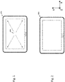
- FIGs 1 to 5 show an exemplary tablet application.
- the inventive solution can be implemented to mobile devices like phones or ultrabooks. Other than these particular applications any other application, in particular with capacitive touch, is possible.
- Capacitive touch screen 104 is highly beneficial since it also detects finger 103 positions.
- pressure sensor 102 is embedded inside device 101. The location of the sensor means 102 is preferably in the centre of the screen 105 but it is also possible to place the pressure sensor means 102 spaced apart from the centre. It is also possible to use multiple pressure sensor means 102. Highly preferably are multiple sensor means, in particular and not belonging to the claimed invention multiple pressure sensor means 102 embedded into the battery 107 of the device 101 (cf. Fig. 4 ).
- the disclosed invention preferably concerns a pressure sensing method in particular for capacitive touch screens 104, wherein a pressure sensor means 102 is preferably located on a battery 107, or, in an embodiment which does not belong to the claimed invention, the pressure sensor means102 is preferably located inside a battery.
- the sensor means 102 is preferably a thin sensor, in particular when the device 101 is a mobile device.
- Such a pressure sensor means 102 can be one or more piezo electric sensor/s and/or one or more magnetostrictive sensor/s or any other technology.
- Analogue values are preferably read by a MCU or main IC or any other ADC and read values are preferably converted to digital. The sampled and quantized values have single dimension.
- 0V-15V supplied from e.g. a piezo pressure sensor are preferably converted to 0-1000 integer values inside MCU.
- 0-1000 is a scalar, at the center of the matrix the values are near 1 (0.9-1 etc.) and they are decreasing by getting closer to the corners.
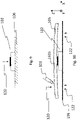
- Fig. 6 shows a side view of a screen 105, wherein underneath the screen 105 a pressure sensor means 102 is arranged.
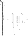
- the pressure sensor means 102 measures various pressure levels according to where it is pressed; preferably a 3D matrix is provided to measure exact values as shown in Fig. 7 .
- the 3D matrix is used to compensate read values of the sensor means 102.
- Using only XxY axis values is not enough for correct measurement, because display screen 105 is not homogenous mechanically in all directions.
- Z axis values are used to compensate effects of several optical components.
- the 2D surface part of XxYxZ is XxY.
- the XxY matrix is created either heuristically (experimental) or simulation or combination of both during design stage.
- Possible methods are a vibrating sample screen and/or measuring displacement with laser vibrometer (or accelerometer) and obtaining correction multipliers.
- Z represents the vertical correction values, in particular representing properties of the LCD Cell, optical films 108 and/or LGP/LGF (if LCD screen is used) respectively and all have different bending stiffness. Again either heuristically (experimental) or simulation or combination is used to determine coefficients. Wherein each component can be analyzed individually and the properties of the screen 105 can be computed by adding all component properties. Alternatively the whole screen 105 is analyzed.
- the optimum place for the pressure sensor means 102 will be the center of the screen 105. If it is possible to use more than one sensor the optimal place can be changed. Of course it is possible to move the pressure sensor means 102 to another position if mechanical limitations occur.
- the 3D matrix can be adapted according to new position. The usage of multiple pressure sensor means 102 is also possible and increases accuracy.
- the pressure sensor means 102 can be used alternatively, in an embodiment not covered by the claims, or additionally, in another embodiment, as a safety sensor for the battery 107.
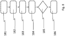
- Fig. 8 shows a preferred process of the inventive method: The first step 182 represents the detection of touch, then the coordinates on the touch screen 105 are determined. As a next step 183 a pressure sensor means signal is detected and the signal level is normalized, in particular by means of a 3D matrix, in a further step 184. Then, the force strength is determined in step 185 and in step 186 the touch force is reported.
- Fig. 9 shows an ideal case for measuring pressure 120 with a pressure sensor means 102 arranged on a rigid element 106, in particular an infinite rigid plane with infinite mass.
- FIG. 10 shows the pressure application of Fig. 9 in a real case. It can be understood from this illustration that the pressure 120 applied by a human finger 103 is in the majority of all cases applied in a distance to the center of the pressure sensor means 102. Thus a correction of the pressure value detected has to be carried out for the determination of the pressure applied at the location where the finger 103 touches the screen 105. This correction is done by the location-pressure-function.
- Reference number 122 indicates a user hand or any other fixed plane like a table top, in particular for enhancing the rigidy of the element 106.
- the rigid element 106 is a finite plane with finite mass, wherein the stiffness of the plane is much higher (preferably multiple times higher) than the stiffness of LCD k plane, wherein the stiffness of LCD and/or wherein the k plane is preferably >> k LCD.
- a correction of the pressure value detected has to be carried out for the determination of the pressure applied at the location where the finger 103 touches the screen 105 and also for the aging of the properties of the device 101, in particular the stiffness of the screen 105.
- This correction is done by the location-pressure-function that incorporates one or multiple aging-correction values of an aging database or an aging-correction function.
- bendability varies in time due to aging.
- Another aging matrix or single variable which is or represents the function of time is used to compensate aging effects. This coefficient is also determined either heuristically (experimental) or by simulation or by a combination thereof.
- the aging function is preferably a scalar multiplication with an aging matrix.
- the aging function can be a kind of Arrhenius eq., in particular exponential and/or depended on time.
- All these matrices depended on screen options and values are changed if screen and mechanic design of device changed with another feature and all these matrices can be stored in memory as look up table, according to screen options, which creates greater manufacturability.
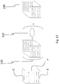
- fig. 13 shows from left to right a matrix, an aging correction matrix and an aging corrected matrix 134, wherein reference number 130 indicates an entrywise product and wherein reference number 132 indicates an aging function, in particular depending on time.
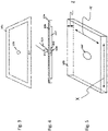
- Fig. 14 shows an assembly group comprising a battery 107, a protection circuit 147, wires 148 and a pressure sensor means 102.
- the battery 107 preferably comprises two terminals 145 and 146, wherein the first terminal 145 is a negative terminal and wherein the second terminal 146 is a positive terminal. Between the terminals 145, 146 is/are preferably a fuse 150 and/or the protective circuit 147 arranged.
- the protective circuit 147 is preferably via wires 148 connected or connectable with a processor unit 152 and/or a screen 105 of a device 101.
- the battery 107 preferably comprises a multilayer arrangement. One layer is preferably constituted by a cathode 144, in particular a cathode on aluminum. Above that cathode 144 is a first separator 141 arranged.
- anode 142 in particular on copper foil
- anode 142 is arranged above the first separator 141 .
- a second separator 143 arranged above the anode 142 .
- the pressure sensor means 102 is connected to or arranged on the second separator 143.
- the second separator 143 and the pressure sensor means are preferably, in an embodiment which does not belong to the claimed invention, covered by a pouch 140, in particular a foil pouch.
- Reference number 149 shows schematically the operation of the battery 107.
- the pressure sensor means 102 can be a piezo sensor (or any other pressure sensor), in particular a sensor different from optical solutions, and therefore preferably needs to be fixed to a surface or plane (which is rigid and not bendable) and then it can measure the pressure applied to the other side correctly. Because LCD screens are not rigid enough and since pressure over LCD has to be measured, it is preferably necessary to fix the pressure sensor means 102 on a rigid and infinite plane.
- a reference plane is required which is much more rigid and has more mass than the LCD screen 105 itself.
- this surface becomes the reference surface.
- battery or back cover can be bend, but they are stiff enough and stiffer than LCD.
- the pressure sensor means 102 can be placed inside a battery, in particular a li-ion battery, which has anode-cathode and separator assembly highly rigid or also it can be placed on a frame, in particular a middle frame, if available (which can e.g. be made of or can comprise magnesium or aluminum alloy).
- the method or device arrangement does not differ whether the pressure sensor means 102 is placed on a frame, according to an embodiment covered by the claimed invention, or, according to an embodiment which does not belong to the claimed invention, inside the battery packaging.
- Using a battery has an advantage during manufacturing and cabling, wherein the middle frame preferably comprises or consists of magnesium and/or aluminum.
Claims (11)
- Vorrichtung (101), insbesondere Multimedia-Vorrichtung,das mindestens aufweisteinen Bildschirm (105),eine Prozessoreinheit (152) undmindestens ein Drucksensormittel (102),wobei das Drucksensormittel (102) an einem starren Element (106) angebracht ist,wobei das starre Element (106) starrer ist als der Bildschirm (105),wobei das starre Element (106) auf einer Seite des Sensormittels (102) angeordnet ist undwobei der Bildschirm (105) auf einer gegenüberliegenden Seite der Sensormittel (102) angeordnet ist,wobei der Bildschirm (105) direkt auf dem Sensormittel (102) angeordnet ist,wobei eine Ortserkennungseinheit bereitgestellt ist, wobei die Ortserkennungseinheit konfiguriert ist, um ein Ortssignal auszugeben,wobei das Ortssignal Ortsinformationen zur Identifizierung des Ortes bereitstellt, an dem Druck auf den Bildschirm (105) ausgeübt wird,wobei das Drucksensormittel (102) so konfiguriert ist, dass es ein Drucksignal ausgibt,wobei das Drucksignal eine Druckinformation über den von dem Drucksensormittel (102) gemessenen Druck bereitstellt,wobei die Prozessoreinheit (152) mittels einer Ortsdruckfunktion einen Druckwert für den auf den Bildschirm (105) ausgeübten Druck ermittelt,wobei die Orts-Druck-Funktion zumindest eine Abhängigkeit zwischen der Ortsinformation und der Druckinformation definiert undwobei die Prozessoreinheit (152) eine Funktion, eine Operation oder einen Effekt in Abhängigkeit von dem Druckwert bewirktwobei die Ortsinformation durch einen Ortswert oder eine Mehrzahl von in einer Reihe erfassten Ortswerten definiert ist, wobei jeder Ortswert einen X-Koordinatenwert und einen Y-Koordinatenwert aufweist,
undein Korrekturwert Z von den Biegeeigenschaften des Bildschirms (105) an den jeweiligen X- und Y-Koordinaten abhängtmindestens eine Datenbank bereitgestellt wird,wobei die Datenbank mit der Prozessoreinheit (152) verbunden ist undwobei die Datenbank Korrekturwerte Z für mehrere Stellen auf der Oberfläche des Bildschirms (105) bereitstellt,wobei mittels der Ortsdruckfunktion in Abhängigkeit von der Ortsinformation ein Korrekturwert Z aus der Datenbank ausgewählt wird undwobei die Ortsdruckfunktion den auf den Bildschirm wirkenden Druck durch Manipulation der Druckinformation mit dem Korrekturwert Z berechnet, dadurch gekennzeichnet, dass die Ortsdruckfunktion auch einen oder mehrere Alterungskorrekturwerte einer Alterungsdatenbank oder einer Alterungskorrekturfunktion einbezieht,wobei der Alterungskorrekturwert einen Parameter zur Eliminierung von Änderungen mindestens einer Bildschirmeigenschaft, insbesondere der Steifigkeit, repräsentiert,wobei die mehreren Alterungskorrekturwerte einen Parameter zur Eliminierung von Änderungen mindestens einer Bildschirmeigenschaft, insbesondere der Steifigkeit, an unterschiedlichen Stellen repräsentieren,wobei die Alterungskorrekturfunktion einen Parameter zur Eliminierung von Änderungen mindestens einer Bildschirmeigenschaft, insbesondere der Steifigkeit, in Abhängigkeit von Orten des Bildschirms (105) repräsentiert,wobei die Alterungs-Korrekturfunktion vorzugsweise auf der Arrhenius-Gleichung oder einer modifizierten Arrhenius-Gleichung basiert. - Vorrichtung gemäß einem der vorhergehenden Ansprüche,
dadurch gekennzeichnet, dassdas Drucksensormittel (102) an einer Batterie angeordnet ist,wobei die Batterie einen positiven Anschluss (146) und einen negativen Anschluss (145) aufweist, wobei elektrische Energie zum Betreiben der Vorrichtung (101) über eine Verbindung bereitgestellt wird, die den Pluspol (146) mit dem Minuspol (145) koppelt. - Vorrichtung gemäß Anspruch 2,
dadurch gekennzeichnet, dassdie Batterie (107) eine Kathode (144) und eine Anode (142) aufweist, wobei Kathode (144) und Anode (142) durch einen ersten Separator (141) voneinander getrennt sind, die Batterie (107) ferner einen zweiten Separator (143) aufweist, wobei oberhalb der Anode (142) ein zweiter Separator (143) angeordnet ist, wobei das Drucksensormittel (102) mit dem zweiten Separator (102) verbunden oder an diesem angeordnet ist, undwobei das starre Element (106) zumindest durch den zweiten Separator (143) materialisiert ist. - Vorrichtung gemäß einem der vorhergehenden Ansprüche 1 bis 3,
dadurch gekennzeichnet, dass,
das starre Element (106) ein Teil des Gehäuses der Vorrichtung (101) ist, insbesondere ein Rahmen zur Befestigung von Vorrichtungskomponenten und/oder zur Stabilisierung. - Vorrichtung gemäß den Ansprüchen 2 bis 4,
dadurch gekennzeichnet, dassder Minuspol (145) und der Pluspol (146) und das Drucksensormittel (102) elektrisch mit einer Schutzschaltung (147) gekoppelt sind,wobei die Schutzschaltung (147) über eine Verbindung mit der Prozessoreinheit (152) und/oder mit dem Bildschirm (105) verbunden ist undwobei über die Verbindung Strom und Daten von der Schutzschaltung (147) zur Prozessoreinheit (152) und/oder zum Bildschirm (105) übertragen werden. - Vorrichtung gemäß einem der vorhergehenden Ansprüche,
dadurch gekennzeichnet, dasseine Befehlsdatenbank bereitgestellt wird,wobei die Befehlsdatenbank Befehle und/oder Routinen bereitstellt,wobei die Prozessoreinheit (152) mindestens einen Befehl und/oder eine Routine in Abhängigkeit von dem Druckwert und/oder einer jeweiligen Operation auswählt. - Vorrichtung gemäß einem der vorhergehenden Ansprüche,
dadurch gekennzeichnet, dassein Gefahrendruckwert vorgegeben und in einem Datenspeichermittel gespeichert ist,wobei die Prozessoreinheit (152) eine Sicherheitsroutine, insbesondere eine Leistungsreduzierung, ausführt, wenn der ermittelte Druckwert oberhalb des Gefahrendruckwertes liegt. - Vorrichtung gemäß Anspruch 7,
dadurch gekennzeichnet, dass,der Gefahrendruckwert mindestens doppelt so hoch ist wie der durchschnittliche Druckwert, der für die Auswahl eines möglichen Befehls und/oder einer Routine einer jeweiligen Operation erforderlich ist,wobei alle jeweiligen von der Prozessoreinheit (152) ausführbaren Operationen anhand von Druckwerten auswählbar sind,wobei alle Druckwerte zur Auswahl der jeweiligen Operationen in einem vordefinierten Druckwertebereich liegen. - Vorrichtung gemäß einem der vorhergehenden Ansprüche 1 bis 8,
dadurch gekennzeichnet, dassdie Vorrichtung (101) eine Multimedia-Vorrichtung ist,wobei der Bildschirm (105) ein kapazitiver Bildschirm (105) ist,wobei der kapazitive Bildschirm (105) eine dreidimensionale (X-, Y-, Z-) Matrix definiert,wobei die Ortserkennungseinheit eine Komponente des kapazitiven Bildschirms (105) ist und X- und Y-Koordinaten des jeweiligen Ortes erkennt,
undwobei Z-Koordinaten zur Kompensation mindestens eines Effekts mindestens einer optischen Komponente, insbesondere der Biegung einer oder mehrerer Komponenten des Bildschirms, wie LCD-Zelle, optische Folien, LGP/LGF, erfasst und verarbeitet werden. - Verfahren,
das mindestens die folgenden Schritte aufweist:Bereitstellen einer Vorrichtung (101), die mindestens einen Bildschirm (105), eine Prozessoreinheit (152) und mindestens ein Drucksensormittel (102) aufweist,wobei das Drucksensormittel (102) an einem starren Element (106) angebracht ist,wobei das starre Element (106) starrer ist als der Bildschirm (105),wobei das starre Element (106) auf einer Seite des Sensormittels (102) angeordnet ist undwobei der Bildschirm (105) auf einer gegenüberliegenden Seite der Sensormittel (102) angeordnet ist,wobei der Bildschirm (105) direkt auf dem Sensormittel (102) angeordnet ist,wobei eine Ortserkennungseinheit bereitgestellt ist,Ausgeben eines Ortssignals durch die Ortserkennungseinheit,wobei das Ortssignal Ortsinformationen zur Identifizierung des Ortes bereitstellt, an dem Druck auf den Bildschirm (105) ausgeübt wird,Ausgeben eines Drucksignals durch das Drucksensormittel (102),wobei das Drucksignal Druckinformationen über den von dem Drucksensormittel (102) gemessenen Druck bereitstellt,wobei die Prozessoreinheit (152) mittels einer Ortsdruckfunktion einen Druckwert für den auf den Bildschirm (105) ausgeübten Druck ermittelt,wobei die Orts-Druck-Funktion zumindest eine Abhängigkeit zwischen der Ortsinformation und der Druckinformation definiert undwobei die Prozessoreinheit (152) eine Funktion, eine Operation oder einen Effekt in Abhängigkeit von dem Druckwert bewirkt,wobei die Ortsinformation durch einen Ortswert oder eine Mehrzahl von in einer Reihe erfassten Ortswerten definiert ist, wobei jeder Ortswert einen X-Koordinatenwert und einen Y-Koordinatenwert aufweist,
undein Korrekturwert Z von den Biegeeigenschaften des Bildschirms (105) an den jeweiligen X- und Y-Koordinaten abhängtmindestens eine Datenbank bereitgestellt wird,wobei die Datenbank mit der Prozessoreinheit (152) verbunden ist undwobei die Datenbank die Korrekturwerte Z für mehrere Stellen auf der Oberfläche des Bildschirms (105) bereitstellt,wobei mittels der Ortsdruckfunktion in Abhängigkeit von der Ortsinformation ein Korrekturwert Z aus der Datenbank ausgewählt wird undwobei die Ortsdruckfunktion den auf den Bildschirm wirkenden Druck durch Manipulation der Druckinformation mit dem Korrekturwert berechnet,dadurch gekennzeichnet, dassdie Ortsdruckfunktion auch einen oder mehrere Alterungskorrekturwerte aus einer Alterungsdatenbank oder einer Alterungskorrekturfunktion einbezieht,wobei der Alterungskorrekturwert einen Parameter zur Eliminierung von Änderungen mindestens einer Bildschirmeigenschaft, insbesondere der Steifigkeit, repräsentiert,wobei die mehreren Alterungskorrekturwerte einen Parameter zur Eliminierung von Änderungen mindestens einer Bildschirmeigenschaft, insbesondere der Steifigkeit, an unterschiedlichen Stellen repräsentieren,wobei die Alterungskorrekturfunktion einen Parameter zur Eliminierung von Änderungen mindestens einer Bildschirmeigenschaft, insbesondere der Steifigkeit, in Abhängigkeit von Orten des Bildschirms (105) repräsentiert,wobei die Alterungs-Korrekturfunktion vorzugsweise auf der Arrhenius-Gleichung oder einer modifizierten Arrhenius-Gleichung basiert. - Verfahren gemäß Anspruch 10,
dadurch gekennzeichnet, dass
die Korrekturwerte Z auf gemessenen oder simulierten Werten in Bezug auf das jeweilige Bildschirm-Design der Vorrichtung und in Bezug auf jeweilige X-/Y-Koordinaten beruhen.
Priority Applications (7)
| Application Number | Priority Date | Filing Date | Title |
|---|---|---|---|
| EP15199481.1A EP3179341B1 (de) | 2015-12-11 | 2015-12-11 | Verfahren und vorrichtung zur messung des drucks auf einem bildschirm mit mindestens einem sensor |
| US15/781,904 US11099678B2 (en) | 2015-12-11 | 2016-12-09 | Method and device for sensing pressure applied to a screen with at least one sensor means |
| JP2018527108A JP2019504388A (ja) | 2015-12-11 | 2016-12-09 | 少なくとも1つのセンサ手段を備えたスクリーンに加えられた圧力を検知するための方法及び装置 |
| PCT/EP2016/080394 WO2017097960A2 (en) | 2015-12-11 | 2016-12-09 | Method and device for sensing pressure applied to a screen with at least one sensor means |
| CN201680072919.9A CN108369467B (zh) | 2015-12-11 | 2016-12-09 | 使用至少一个传感器装置感测施加至屏幕的压力的方法和设备 |
| KR1020187015707A KR20180093905A (ko) | 2015-12-11 | 2016-12-09 | 하나 이상의 센서 수단을 통해 스크린에 가해지는 압력을 감지하는 방법 및 디바이스 |
| TR2017/02633A TR201702633A2 (tr) | 2015-12-11 | 2017-02-22 | En az bi̇r sensör aracina sahi̇p bi̇r ekrana uygulanan basinci algilamaya yöneli̇k yöntem ve ci̇haz |
Applications Claiming Priority (1)
| Application Number | Priority Date | Filing Date | Title |
|---|---|---|---|
| EP15199481.1A EP3179341B1 (de) | 2015-12-11 | 2015-12-11 | Verfahren und vorrichtung zur messung des drucks auf einem bildschirm mit mindestens einem sensor |
Publications (2)
| Publication Number | Publication Date |
|---|---|
| EP3179341A1 EP3179341A1 (de) | 2017-06-14 |
| EP3179341B1 true EP3179341B1 (de) | 2022-07-27 |
Family
ID=55027259
Family Applications (1)
| Application Number | Title | Priority Date | Filing Date |
|---|---|---|---|
| EP15199481.1A Active EP3179341B1 (de) | 2015-12-11 | 2015-12-11 | Verfahren und vorrichtung zur messung des drucks auf einem bildschirm mit mindestens einem sensor |
Country Status (7)
| Country | Link |
|---|---|
| US (1) | US11099678B2 (de) |
| EP (1) | EP3179341B1 (de) |
| JP (1) | JP2019504388A (de) |
| KR (1) | KR20180093905A (de) |
| CN (1) | CN108369467B (de) |
| TR (1) | TR201702633A2 (de) |
| WO (1) | WO2017097960A2 (de) |
Families Citing this family (4)
| Publication number | Priority date | Publication date | Assignee | Title |
|---|---|---|---|---|
| KR101910518B1 (ko) * | 2017-04-11 | 2018-10-22 | 삼성전자주식회사 | 생체 센서 및 생체 센서를 포함하는 장치 |
| DE112018006732B4 (de) * | 2018-01-31 | 2022-03-10 | Mitsubishi Electric Corporation | Berührungsbildschirmvorrichtung |
| CN109669581B (zh) * | 2018-12-29 | 2021-06-15 | 联想(北京)有限公司 | 输入装置、输入方法和计算设备 |
| CN110908542A (zh) * | 2019-11-29 | 2020-03-24 | 上海众链科技有限公司 | 智能终端的屏幕组件、智能终端、屏幕压感检测方法及计算机可读存储介质 |
Citations (1)
| Publication number | Priority date | Publication date | Assignee | Title |
|---|---|---|---|---|
| WO2016164193A1 (en) * | 2015-04-09 | 2016-10-13 | Microsoft Technology Licensing, Llc | Force-sensitive touch sensor compensation |
Family Cites Families (27)
| Publication number | Priority date | Publication date | Assignee | Title |
|---|---|---|---|---|
| JP2000231446A (ja) | 1999-02-10 | 2000-08-22 | Sharp Corp | 表示一体型タブレット装置及びタブレット自動補正プログラムを記憶した記憶媒体 |
| US20080094367A1 (en) * | 2004-08-02 | 2008-04-24 | Koninklijke Philips Electronics, N.V. | Pressure-Controlled Navigating in a Touch Screen |
| US9182837B2 (en) * | 2005-11-28 | 2015-11-10 | Synaptics Incorporated | Methods and systems for implementing modal changes in a device in response to proximity and force indications |
| US9329719B2 (en) * | 2007-03-15 | 2016-05-03 | Apple Inc. | Hybrid force sensitive touch devices |
| US20090195959A1 (en) * | 2008-01-31 | 2009-08-06 | Research In Motion Limited | Electronic device and method for controlling same |
| US8633916B2 (en) * | 2009-12-10 | 2014-01-21 | Apple, Inc. | Touch pad with force sensors and actuator feedback |
| JP4935917B2 (ja) * | 2010-03-19 | 2012-05-23 | 株式会社デンソー | 携帯機 |
| EP2580647A1 (de) | 2010-06-11 | 2013-04-17 | 3M Innovative Properties Company | Positionsberührungssensor mit kraftmessung |
| TR201009784A1 (tr) * | 2010-11-26 | 2012-06-21 | Vestel Elektroni̇k Sanayi̇ Ve Ti̇caret A.Ş. | Sanal klavye yazım yöntemi. |
| EP2659337B1 (de) * | 2010-12-31 | 2021-07-28 | Nokia Technologies Oy | Anzeigevorrichtung mit erzeugung eines audioausganges und haptischen ausganges |
| US9136509B2 (en) * | 2011-05-27 | 2015-09-15 | Apple Inc. | Battery cell with an integrated pouch metal foil terminal |
| JP5833863B2 (ja) * | 2011-08-24 | 2015-12-16 | 日東電工株式会社 | 透明導電性フィルムおよびその製造方法 |
| JP5874739B2 (ja) * | 2011-12-16 | 2016-03-02 | 株式会社村田製作所 | タッチ式操作入力装置 |
| JP5861439B2 (ja) | 2011-12-19 | 2016-02-16 | ミツミ電機株式会社 | 押圧力検出装置 |
| JP5137150B1 (ja) * | 2012-02-23 | 2013-02-06 | 株式会社ワコム | 手書き情報入力装置及び手書き情報入力装置を備えた携帯電子機器 |
| DE102012207999A1 (de) | 2012-05-14 | 2013-11-14 | Robert Bosch Gmbh | Hüllfolie für ein galvanisches Element, elektrochemischer Speicher, elektrochemisches Speichersystem, flexible Folie für eine Hülle eines galvanischen Elements und Verfahren zum Bestimmen einer Zustandsgröße eines elektrochemischen Speichers |
| WO2013183938A1 (ko) | 2012-06-08 | 2013-12-12 | 주식회사 케이엠티글로벌 | 공간상의 위치인식을 통한 사용자인터페이스 방법 및 장치 |
| US9250754B2 (en) * | 2012-09-27 | 2016-02-02 | Google Inc. | Pressure-sensitive trackpad |
| US9239627B2 (en) | 2012-11-07 | 2016-01-19 | Panasonic Intellectual Property Corporation Of America | SmartLight interaction system |
| KR102058699B1 (ko) * | 2013-01-24 | 2019-12-26 | 삼성디스플레이 주식회사 | 터치 및 휨 감지 기능을 가지는 플렉서블 표시장치 |
| US9864463B2 (en) * | 2013-03-05 | 2018-01-09 | Atmel Corporation | Touch panel deformation compensation |
| US20140342193A1 (en) * | 2013-05-17 | 2014-11-20 | Tenergy Corporation | Smart battery system |
| US9182864B2 (en) | 2013-06-03 | 2015-11-10 | Rajkumari Mohindra | Pressure sensitive projected capacitive touch sensing |
| US9660301B2 (en) * | 2013-10-29 | 2017-05-23 | Xiaomi Inc. | Methods and devices for battery protection |
| CN103812090B (zh) | 2013-10-29 | 2017-08-01 | 小米科技有限责任公司 | 电子设备、电池保护方法和装置 |
| US20150138112A1 (en) * | 2013-11-20 | 2015-05-21 | Nextinput, Inc. | Force sensor module for applying a preload force to a force sensor |
| US9921679B2 (en) * | 2015-10-11 | 2018-03-20 | Pressure Profile Systems Inc. | Force-sensing touch screen input device |
-
2015
- 2015-12-11 EP EP15199481.1A patent/EP3179341B1/de active Active
-
2016
- 2016-12-09 KR KR1020187015707A patent/KR20180093905A/ko not_active Application Discontinuation
- 2016-12-09 JP JP2018527108A patent/JP2019504388A/ja active Pending
- 2016-12-09 CN CN201680072919.9A patent/CN108369467B/zh active Active
- 2016-12-09 WO PCT/EP2016/080394 patent/WO2017097960A2/en active Application Filing
- 2016-12-09 US US15/781,904 patent/US11099678B2/en active Active
-
2017
- 2017-02-22 TR TR2017/02633A patent/TR201702633A2/tr unknown
Patent Citations (1)
| Publication number | Priority date | Publication date | Assignee | Title |
|---|---|---|---|---|
| WO2016164193A1 (en) * | 2015-04-09 | 2016-10-13 | Microsoft Technology Licensing, Llc | Force-sensitive touch sensor compensation |
Also Published As
| Publication number | Publication date |
|---|---|
| US20200333938A1 (en) | 2020-10-22 |
| CN108369467B (zh) | 2021-07-13 |
| EP3179341A1 (de) | 2017-06-14 |
| WO2017097960A3 (en) | 2017-07-13 |
| JP2019504388A (ja) | 2019-02-14 |
| WO2017097960A2 (en) | 2017-06-15 |
| TR201702633A2 (tr) | 2018-09-21 |
| KR20180093905A (ko) | 2018-08-22 |
| CN108369467A (zh) | 2018-08-03 |
| US11099678B2 (en) | 2021-08-24 |
Similar Documents
| Publication | Publication Date | Title |
|---|---|---|
| EP3179341B1 (de) | Verfahren und vorrichtung zur messung des drucks auf einem bildschirm mit mindestens einem sensor | |
| US8169332B2 (en) | Tactile device with force sensitive touch input surface | |
| US10831301B2 (en) | Pressure detecting and information input device to amplify an output | |
| CN203457129U (zh) | 组合的力和接近感测设备及关联的便携式装置 | |
| TWI543049B (zh) | 電容式觸控輸入裝置之機械形變補償 | |
| TWI675191B (zh) | 顯示一體型輸入裝置 | |
| US20090066673A1 (en) | Integrated force sensitive lens and software | |
| JP2005526333A (ja) | タッチスクリーンの機械歪みを調整すべく較正パラメータを用いて押圧タッチスクリーン上の押圧位置を特定する方法およびシステム | |
| KR101117841B1 (ko) | 터치 감지형 디스플레이를 포함한 포터블 전자 디바이스 및 그 제어 방법 | |
| US10275069B2 (en) | Pressure resistant force sensing enclosure | |
| CN106569628A (zh) | 力感应触摸屏输入装置 | |
| KR20170103026A (ko) | 용량성 감지에 기초한 힘 결정 | |
| CN108027679B (zh) | 力敏设备的校准 | |
| KR102057567B1 (ko) | 터치 입력 장치의 터치 압력 감도 보정 방법 및 컴퓨터 판독 가능한 기록 매체 | |
| KR102447185B1 (ko) | 포스 센서의 압력값 보상 방법 및 이를 사용하는 전자 장치 | |
| TW201706753A (zh) | 電子裝置 | |
| US20170177141A1 (en) | Pressure Detection Method for In-cell Touch Display and Mobile Device Using the Same | |
| KR20200072263A (ko) | 기생 커패시턴스를 식별하기 위한 전자 장치 및 방법 | |
| CN114089860A (zh) | 电子设备的压感控制方法、装置、电子设备及介质 | |
| US20170123549A1 (en) | Method and device for locating interaction on a touch-sensitive surface | |
| JP2021026663A (ja) | タッチパネル及び表示装置 | |
| US10488998B2 (en) | Touch-sensitive interface with shell mounting, touch-sensitive shell, and mechanical stress sensors | |
| CN109753177B (zh) | 一种中框模组 | |
| KR20120053205A (ko) | 클램프 압력측정 장치 | |
| US10051724B1 (en) | Structural ground reference for an electronic component of a computing device |
Legal Events
| Date | Code | Title | Description |
|---|---|---|---|
| PUAI | Public reference made under article 153(3) epc to a published international application that has entered the european phase |
Free format text: ORIGINAL CODE: 0009012 |
|
| STAA | Information on the status of an ep patent application or granted ep patent |
Free format text: STATUS: THE APPLICATION HAS BEEN PUBLISHED |
|
| AK | Designated contracting states |
Kind code of ref document: A1 Designated state(s): AL AT BE BG CH CY CZ DE DK EE ES FI FR GB GR HR HU IE IS IT LI LT LU LV MC MK MT NL NO PL PT RO RS SE SI SK SM TR |
|
| AX | Request for extension of the european patent |
Extension state: BA ME |
|
| STAA | Information on the status of an ep patent application or granted ep patent |
Free format text: STATUS: REQUEST FOR EXAMINATION WAS MADE |
|
| 17P | Request for examination filed |
Effective date: 20171214 |
|
| RBV | Designated contracting states (corrected) |
Designated state(s): AL AT BE BG CH CY CZ DE DK EE ES FI FR GB GR HR HU IE IS IT LI LT LU LV MC MK MT NL NO PL PT RO RS SE SI SK SM TR |
|
| STAA | Information on the status of an ep patent application or granted ep patent |
Free format text: STATUS: EXAMINATION IS IN PROGRESS |
|
| 17Q | First examination report despatched |
Effective date: 20180601 |
|
| STAA | Information on the status of an ep patent application or granted ep patent |
Free format text: STATUS: EXAMINATION IS IN PROGRESS |
|
| STAA | Information on the status of an ep patent application or granted ep patent |
Free format text: STATUS: EXAMINATION IS IN PROGRESS |
|
| RIC1 | Information provided on ipc code assigned before grant |
Ipc: H01M 50/578 20210101ALI20220112BHEP Ipc: H01M 10/42 20060101ALI20220112BHEP Ipc: G06F 3/046 20060101ALI20220112BHEP Ipc: G06F 3/044 20060101ALI20220112BHEP Ipc: G06F 3/041 20060101AFI20220112BHEP |
|
| GRAP | Despatch of communication of intention to grant a patent |
Free format text: ORIGINAL CODE: EPIDOSNIGR1 |
|
| STAA | Information on the status of an ep patent application or granted ep patent |
Free format text: STATUS: GRANT OF PATENT IS INTENDED |
|
| INTG | Intention to grant announced |
Effective date: 20220222 |
|
| GRAS | Grant fee paid |
Free format text: ORIGINAL CODE: EPIDOSNIGR3 |
|
| GRAA | (expected) grant |
Free format text: ORIGINAL CODE: 0009210 |
|
| STAA | Information on the status of an ep patent application or granted ep patent |
Free format text: STATUS: THE PATENT HAS BEEN GRANTED |
|
| AK | Designated contracting states |
Kind code of ref document: B1 Designated state(s): AL AT BE BG CH CY CZ DE DK EE ES FI FR GB GR HR HU IE IS IT LI LT LU LV MC MK MT NL NO PL PT RO RS SE SI SK SM TR |
|
| REG | Reference to a national code |
Ref country code: CH Ref legal event code: EP |
|
| REG | Reference to a national code |
Ref country code: DE Ref legal event code: R082 Ref document number: 602015080014 Country of ref document: DE Representative=s name: KEHL, ASCHERL, LIEBHOFF & ETTMAYR - PATENTANWA, DE |
|
| REG | Reference to a national code |
Ref country code: DE Ref legal event code: R096 Ref document number: 602015080014 Country of ref document: DE |
|
| REG | Reference to a national code |
Ref country code: AT Ref legal event code: REF Ref document number: 1507492 Country of ref document: AT Kind code of ref document: T Effective date: 20220815 |
|
| REG | Reference to a national code |
Ref country code: IE Ref legal event code: FG4D |
|
| REG | Reference to a national code |
Ref country code: LT Ref legal event code: MG9D |
|
| REG | Reference to a national code |
Ref country code: NL Ref legal event code: MP Effective date: 20220727 |
|
| PG25 | Lapsed in a contracting state [announced via postgrant information from national office to epo] |
Ref country code: SE Free format text: LAPSE BECAUSE OF FAILURE TO SUBMIT A TRANSLATION OF THE DESCRIPTION OR TO PAY THE FEE WITHIN THE PRESCRIBED TIME-LIMIT Effective date: 20220727 Ref country code: RS Free format text: LAPSE BECAUSE OF FAILURE TO SUBMIT A TRANSLATION OF THE DESCRIPTION OR TO PAY THE FEE WITHIN THE PRESCRIBED TIME-LIMIT Effective date: 20220727 Ref country code: PT Free format text: LAPSE BECAUSE OF FAILURE TO SUBMIT A TRANSLATION OF THE DESCRIPTION OR TO PAY THE FEE WITHIN THE PRESCRIBED TIME-LIMIT Effective date: 20221128 Ref country code: NO Free format text: LAPSE BECAUSE OF FAILURE TO SUBMIT A TRANSLATION OF THE DESCRIPTION OR TO PAY THE FEE WITHIN THE PRESCRIBED TIME-LIMIT Effective date: 20221027 Ref country code: NL Free format text: LAPSE BECAUSE OF FAILURE TO SUBMIT A TRANSLATION OF THE DESCRIPTION OR TO PAY THE FEE WITHIN THE PRESCRIBED TIME-LIMIT Effective date: 20220727 Ref country code: LV Free format text: LAPSE BECAUSE OF FAILURE TO SUBMIT A TRANSLATION OF THE DESCRIPTION OR TO PAY THE FEE WITHIN THE PRESCRIBED TIME-LIMIT Effective date: 20220727 Ref country code: LT Free format text: LAPSE BECAUSE OF FAILURE TO SUBMIT A TRANSLATION OF THE DESCRIPTION OR TO PAY THE FEE WITHIN THE PRESCRIBED TIME-LIMIT Effective date: 20220727 Ref country code: FI Free format text: LAPSE BECAUSE OF FAILURE TO SUBMIT A TRANSLATION OF THE DESCRIPTION OR TO PAY THE FEE WITHIN THE PRESCRIBED TIME-LIMIT Effective date: 20220727 Ref country code: ES Free format text: LAPSE BECAUSE OF FAILURE TO SUBMIT A TRANSLATION OF THE DESCRIPTION OR TO PAY THE FEE WITHIN THE PRESCRIBED TIME-LIMIT Effective date: 20220727 |
|
| PGFP | Annual fee paid to national office [announced via postgrant information from national office to epo] |
Ref country code: GB Payment date: 20221222 Year of fee payment: 8 |
|
| REG | Reference to a national code |
Ref country code: AT Ref legal event code: MK05 Ref document number: 1507492 Country of ref document: AT Kind code of ref document: T Effective date: 20220727 |
|
| PG25 | Lapsed in a contracting state [announced via postgrant information from national office to epo] |
Ref country code: PL Free format text: LAPSE BECAUSE OF FAILURE TO SUBMIT A TRANSLATION OF THE DESCRIPTION OR TO PAY THE FEE WITHIN THE PRESCRIBED TIME-LIMIT Effective date: 20220727 Ref country code: IS Free format text: LAPSE BECAUSE OF FAILURE TO SUBMIT A TRANSLATION OF THE DESCRIPTION OR TO PAY THE FEE WITHIN THE PRESCRIBED TIME-LIMIT Effective date: 20221127 Ref country code: HR Free format text: LAPSE BECAUSE OF FAILURE TO SUBMIT A TRANSLATION OF THE DESCRIPTION OR TO PAY THE FEE WITHIN THE PRESCRIBED TIME-LIMIT Effective date: 20220727 Ref country code: GR Free format text: LAPSE BECAUSE OF FAILURE TO SUBMIT A TRANSLATION OF THE DESCRIPTION OR TO PAY THE FEE WITHIN THE PRESCRIBED TIME-LIMIT Effective date: 20221028 |
|
| PG25 | Lapsed in a contracting state [announced via postgrant information from national office to epo] |
Ref country code: SM Free format text: LAPSE BECAUSE OF FAILURE TO SUBMIT A TRANSLATION OF THE DESCRIPTION OR TO PAY THE FEE WITHIN THE PRESCRIBED TIME-LIMIT Effective date: 20220727 Ref country code: RO Free format text: LAPSE BECAUSE OF FAILURE TO SUBMIT A TRANSLATION OF THE DESCRIPTION OR TO PAY THE FEE WITHIN THE PRESCRIBED TIME-LIMIT Effective date: 20220727 Ref country code: DK Free format text: LAPSE BECAUSE OF FAILURE TO SUBMIT A TRANSLATION OF THE DESCRIPTION OR TO PAY THE FEE WITHIN THE PRESCRIBED TIME-LIMIT Effective date: 20220727 Ref country code: CZ Free format text: LAPSE BECAUSE OF FAILURE TO SUBMIT A TRANSLATION OF THE DESCRIPTION OR TO PAY THE FEE WITHIN THE PRESCRIBED TIME-LIMIT Effective date: 20220727 Ref country code: AT Free format text: LAPSE BECAUSE OF FAILURE TO SUBMIT A TRANSLATION OF THE DESCRIPTION OR TO PAY THE FEE WITHIN THE PRESCRIBED TIME-LIMIT Effective date: 20220727 |
|
| REG | Reference to a national code |
Ref country code: DE Ref legal event code: R097 Ref document number: 602015080014 Country of ref document: DE |
|
| PG25 | Lapsed in a contracting state [announced via postgrant information from national office to epo] |
Ref country code: SK Free format text: LAPSE BECAUSE OF FAILURE TO SUBMIT A TRANSLATION OF THE DESCRIPTION OR TO PAY THE FEE WITHIN THE PRESCRIBED TIME-LIMIT Effective date: 20220727 Ref country code: EE Free format text: LAPSE BECAUSE OF FAILURE TO SUBMIT A TRANSLATION OF THE DESCRIPTION OR TO PAY THE FEE WITHIN THE PRESCRIBED TIME-LIMIT Effective date: 20220727 |
|
| PGFP | Annual fee paid to national office [announced via postgrant information from national office to epo] |
Ref country code: DE Payment date: 20221221 Year of fee payment: 8 |
|
| PLBE | No opposition filed within time limit |
Free format text: ORIGINAL CODE: 0009261 |
|
| STAA | Information on the status of an ep patent application or granted ep patent |
Free format text: STATUS: NO OPPOSITION FILED WITHIN TIME LIMIT |
|
| PG25 | Lapsed in a contracting state [announced via postgrant information from national office to epo] |
Ref country code: AL Free format text: LAPSE BECAUSE OF FAILURE TO SUBMIT A TRANSLATION OF THE DESCRIPTION OR TO PAY THE FEE WITHIN THE PRESCRIBED TIME-LIMIT Effective date: 20220727 |
|
| 26N | No opposition filed |
Effective date: 20230502 |
|
| REG | Reference to a national code |
Ref country code: CH Ref legal event code: PL |
|
| REG | Reference to a national code |
Ref country code: BE Ref legal event code: MM Effective date: 20221231 |
|
| PG25 | Lapsed in a contracting state [announced via postgrant information from national office to epo] |
Ref country code: SI Free format text: LAPSE BECAUSE OF FAILURE TO SUBMIT A TRANSLATION OF THE DESCRIPTION OR TO PAY THE FEE WITHIN THE PRESCRIBED TIME-LIMIT Effective date: 20220727 Ref country code: LU Free format text: LAPSE BECAUSE OF NON-PAYMENT OF DUE FEES Effective date: 20221211 |
|
| PG25 | Lapsed in a contracting state [announced via postgrant information from national office to epo] |
Ref country code: LI Free format text: LAPSE BECAUSE OF NON-PAYMENT OF DUE FEES Effective date: 20221231 Ref country code: IE Free format text: LAPSE BECAUSE OF NON-PAYMENT OF DUE FEES Effective date: 20221211 Ref country code: CH Free format text: LAPSE BECAUSE OF NON-PAYMENT OF DUE FEES Effective date: 20221231 |
|
| PG25 | Lapsed in a contracting state [announced via postgrant information from national office to epo] |
Ref country code: FR Free format text: LAPSE BECAUSE OF NON-PAYMENT OF DUE FEES Effective date: 20221231 Ref country code: BE Free format text: LAPSE BECAUSE OF NON-PAYMENT OF DUE FEES Effective date: 20221231 |
|
| PGFP | Annual fee paid to national office [announced via postgrant information from national office to epo] |
Ref country code: TR Payment date: 20231208 Year of fee payment: 9 |
|
| PG25 | Lapsed in a contracting state [announced via postgrant information from national office to epo] |
Ref country code: HU Free format text: LAPSE BECAUSE OF FAILURE TO SUBMIT A TRANSLATION OF THE DESCRIPTION OR TO PAY THE FEE WITHIN THE PRESCRIBED TIME-LIMIT; INVALID AB INITIO Effective date: 20151211 |