EP3178774A1 - Reach truck - Google Patents
Reach truck Download PDFInfo
- Publication number
- EP3178774A1 EP3178774A1 EP16200298.4A EP16200298A EP3178774A1 EP 3178774 A1 EP3178774 A1 EP 3178774A1 EP 16200298 A EP16200298 A EP 16200298A EP 3178774 A1 EP3178774 A1 EP 3178774A1
- Authority
- EP
- European Patent Office
- Prior art keywords
- assembly
- frame assembly
- straddle
- rear frame
- arm assembly
- Prior art date
- Legal status (The legal status is an assumption and is not a legal conclusion. Google has not performed a legal analysis and makes no representation as to the accuracy of the status listed.)
- Granted
Links
Images

Classifications
-
- B—PERFORMING OPERATIONS; TRANSPORTING
- B66—HOISTING; LIFTING; HAULING
- B66F—HOISTING, LIFTING, HAULING OR PUSHING, NOT OTHERWISE PROVIDED FOR, e.g. DEVICES WHICH APPLY A LIFTING OR PUSHING FORCE DIRECTLY TO THE SURFACE OF A LOAD
- B66F9/00—Devices for lifting or lowering bulky or heavy goods for loading or unloading purposes
- B66F9/06—Devices for lifting or lowering bulky or heavy goods for loading or unloading purposes movable, with their loads, on wheels or the like, e.g. fork-lift trucks
- B66F9/075—Constructional features or details
-
- B—PERFORMING OPERATIONS; TRANSPORTING
- B66—HOISTING; LIFTING; HAULING
- B66F—HOISTING, LIFTING, HAULING OR PUSHING, NOT OTHERWISE PROVIDED FOR, e.g. DEVICES WHICH APPLY A LIFTING OR PUSHING FORCE DIRECTLY TO THE SURFACE OF A LOAD
- B66F9/00—Devices for lifting or lowering bulky or heavy goods for loading or unloading purposes
- B66F9/06—Devices for lifting or lowering bulky or heavy goods for loading or unloading purposes movable, with their loads, on wheels or the like, e.g. fork-lift trucks
- B66F9/075—Constructional features or details
- B66F9/07559—Stabilizing means
-
- B—PERFORMING OPERATIONS; TRANSPORTING
- B66—HOISTING; LIFTING; HAULING
- B66F—HOISTING, LIFTING, HAULING OR PUSHING, NOT OTHERWISE PROVIDED FOR, e.g. DEVICES WHICH APPLY A LIFTING OR PUSHING FORCE DIRECTLY TO THE SURFACE OF A LOAD
- B66F9/00—Devices for lifting or lowering bulky or heavy goods for loading or unloading purposes
- B66F9/06—Devices for lifting or lowering bulky or heavy goods for loading or unloading purposes movable, with their loads, on wheels or the like, e.g. fork-lift trucks
- B66F9/075—Constructional features or details
- B66F9/07513—Details concerning the chassis
-
- B—PERFORMING OPERATIONS; TRANSPORTING
- B66—HOISTING; LIFTING; HAULING
- B66F—HOISTING, LIFTING, HAULING OR PUSHING, NOT OTHERWISE PROVIDED FOR, e.g. DEVICES WHICH APPLY A LIFTING OR PUSHING FORCE DIRECTLY TO THE SURFACE OF A LOAD
- B66F9/00—Devices for lifting or lowering bulky or heavy goods for loading or unloading purposes
- B66F9/06—Devices for lifting or lowering bulky or heavy goods for loading or unloading purposes movable, with their loads, on wheels or the like, e.g. fork-lift trucks
- B66F9/075—Constructional features or details
- B66F9/07504—Accessories, e.g. for towing, charging, locking
-
- B—PERFORMING OPERATIONS; TRANSPORTING
- B66—HOISTING; LIFTING; HAULING
- B66F—HOISTING, LIFTING, HAULING OR PUSHING, NOT OTHERWISE PROVIDED FOR, e.g. DEVICES WHICH APPLY A LIFTING OR PUSHING FORCE DIRECTLY TO THE SURFACE OF A LOAD
- B66F9/00—Devices for lifting or lowering bulky or heavy goods for loading or unloading purposes
- B66F9/06—Devices for lifting or lowering bulky or heavy goods for loading or unloading purposes movable, with their loads, on wheels or the like, e.g. fork-lift trucks
- B66F9/075—Constructional features or details
- B66F9/07513—Details concerning the chassis
- B66F9/07522—Variable length or width chassis
-
- B—PERFORMING OPERATIONS; TRANSPORTING
- B66—HOISTING; LIFTING; HAULING
- B66F—HOISTING, LIFTING, HAULING OR PUSHING, NOT OTHERWISE PROVIDED FOR, e.g. DEVICES WHICH APPLY A LIFTING OR PUSHING FORCE DIRECTLY TO THE SURFACE OF A LOAD
- B66F9/00—Devices for lifting or lowering bulky or heavy goods for loading or unloading purposes
- B66F9/06—Devices for lifting or lowering bulky or heavy goods for loading or unloading purposes movable, with their loads, on wheels or the like, e.g. fork-lift trucks
- B66F9/075—Constructional features or details
- B66F9/08—Masts; Guides; Chains
- B66F9/10—Masts; Guides; Chains movable in a horizontal direction relative to truck
Definitions
- the present invention relates to a reach truck.
- Japanese Patent Application Publication No. 2008-221981 discloses a reach truck that includes a mast assembly having a pair of right and left forks (loading implement) and a straddle arm assembly having a pair of right and left straddle arms that guides the mast assembly to move in the longitudinal direction of the reach truck.
- a cylinder a hydraulic cylinder
- This type of reach truck further includes a rear frame assembly that is joined to the rear end of the straddle arm assembly and accommodates therein a drive unit. The rear end of the straddle arm assembly and the front end of the rear frame assembly are joined together by welding, thus forming a module component.
- the present invention which has been made in view of the above problems, is directed to providing a reach truck that is easy to manufacture.
- a reach truck including a vehicle body, a mast assembly that is disposed in a front part of the vehicle body and has a loading implement, a straddle arm assembly having a pair of right and left straddle arms that guides the mast assembly to move in a longitudinal direction of the straddle arm assembly, and a rear frame assembly that is joined to a rear end of the straddle arm assembly and accommodates therein a drive unit.
- the rear frame assembly includes a joint member through which the rear frame assembly and the straddle arm assembly are joined to each other by a fastening member.
- FIGS. 1 to 4 The following will describe an embodiment of a reach truck according to the present invention with reference to FIGS. 1 to 4 .
- the terms such as front, rear, right, left, upper, lower and the like are used to refer to the positions or directions as viewed from an operator of the reach truck facing in the forward traveling direction of the reach truck.
- the reach truck 10 having a vehicle body 11.
- the reach truck 10 includes a loading equipment 12 located in the front of the vehicle body 11.
- the loading equipment 12 includes a mast assembly 13 that is disposed vertically in the front part of the vehicle body 11, and a pair of right and left forks 13F mounted to the mast assembly 13 through a lift bracket 13A.
- the forks 13F correspond to the loading implement of the present invention.
- the forks 13F are movable in the vertical direction relative to the mast assembly 13 via the lift bracket 13A.
- the vehicle body 11 of the reach truck 10 includes a base frame assembly 14 that forms a base of the vehicle body 11 and an upper frame assembly 15 that is disposed on the base frame assembly 14 and forms a body portion of the vehicle body 11.
- the base frame assembly 14 includes a straddle arm assembly 21 having a pair of right and left straddle arms 20 that guides the mast assembly 13 to move forward or rearward or in the longitudinal direction of the straddle arm assembly 21.
- the base frame assembly 14 further includes a rear frame assembly 31 that is joined to the rear end of the straddle arm assembly 21 on the side opposite to the straddle arms 20.
- the straddle arms 20 have a square columnar shape extending forward.
- a pair of reach cylinders 16 (hydraulic cylinders) is disposed in the lower part of the vehicle body 11.
- Each reach cylinder 16 has a piston rod 16A joined to the mast assembly 13.
- the mast assembly 13 is movable forward and rearward along the straddle arms 20 for a distance within a specified stroke length during the extending and retracting motion of the piston rods 16A of the reach cylinders 16.
- Each straddle arm 20 has in a lower part of the leading end thereof a driven wheel 17.
- the vehicle body 11 has in the lower rear part thereof a steerable drive wheel 18A and a caster wheel 18B.
- the steerable drive wheel 18A is disposed at a position offset leftward from the width center of the vehicle body 11 as seen in the forward moving direction of the reach truck 10 and the caster wheel 18B is spaced rightward at a predetermined distance away from the steerable drive wheel 18A in such a manner that the steerable drive wheel 18A and the caster wheel 18B are provided in a pair in the lateral direction of the vehicle body 11.
- An operator's compartment 19 or a cabin of a stand-up type is provided in the right rear part of the vehicle body 11.
- An instrumental panel 19A is disposed in the front part of the operator's compartment 19 of the vehicle body 11.
- the instrumental panel 19A has an operation control lever 19B for controlling the load-handling operation and the like.
- An upright accommodating box 19C is provided on the left side of the operator's compartment 19 and a steering wheel 19D is provided at the top of the accommodating box 19C.
- the upper frame assembly 15 includes a pair of right and left side members 15A that forms the right and left side portions of the vehicle body 11 and a laterally-extending vertical connecting member 15B through which the side members 15A are connected to each other.
- the connecting member 15B is connected to the side members 15A approximately at the respective longitudinal centers thereof.
- a horizontal partition member 15C is provided on the front side of the connecting member 15B, extending frontward from a position of the connecting member 15B that is above the center of the connecting member 15B as measured in the vertical direction thereof.
- the partition member 15C is joined at opposite lateral sides thereof to the side members 15A.
- the upper frame assembly 15 and the partition member 15C cooperate to form a space for accommodating therein a battery (not shown) below the partition member 15C.
- a pair of L-shaped pillars 15D is provided at the opposite front corners of the partition member 15C, extending upward from the upper surface thereof and an overhead guard 15E is mounted to the top of the pillars 15D.
- a bracket 15F having an L-shaped cross section is fixed to the inner surface of the respective side members 15A at bottom positions thereof that are frontward of the connecting member 15B.
- Each bracket 15F includes a first bracket portion 151F extending upward along the inner surface of the side members 15A and a second bracket portion 152F extending inward of the side members 15A at a right angle relative to the first bracket portion 151 F.
- the first and second bracket portions 151 F, 152F are strip-like members extending in the longitudinal direction of the vehicle body 11.
- Each bracket 15F is fixed at the first bracket portion 151F thereof to the inner surface of its corresponding side member 15A by welding.
- the second bracket portion 152F of each bracket 15F has therethrough two bolt holes 15H that are spaced at a distance in the longitudinal direction.
- Each straddle arm 20 includes a guide rail 20A having a C-shaped cross section and extending on the inner side of the straddle arm 20 in the longitudinal direction of the vehicle body 11 so that the mast assembly 13 is guided to move forward and rearward.
- Each straddle arm 20 has in the upper member thereof two internally-threaded holes 20H spaced in the longitudinal direction at the same distance between two bolt holes 15H in the second bracket portion 152F of the bracket 15F.
- the straddle arm assembly 21 includes a laterally-extending first connecting member 21A through which the straddle arms 20 are connected to each other.
- the first connecting member 21A is connected at the opposite lateral sides thereof to the bottom surfaces of the straddle arms 20 at portions thereof adjacent to the rear ends of the straddle arms 20 to thereby connect the straddle arms 20 to each other.
- Two internally-threaded holes 21 H are formed through the first connecting member 21A at positions adjacent to the lateral side edges thereof and inward of the straddle arms 20.
- the straddle arm assembly 21 further includes a vertical member 22 that continues from the rear end of the first connecting member 21A and extends upward.
- the vertical member 22 extends laterally between the straddle arms 20.
- the straddle arm assembly 21 further includes a second connecting member 21 B that is disposed so as to face the first connecting member 21A from above and through which the pair of straddle arms 20 are connected to each other.
- the first connecting member 21A and the second connecting member 21 B correspond to the connecting member of the present invention.
- the second connecting member 21 B is connected at the opposite lateral sides thereof to the upper parts of the straddle arms 20 to thereby connect the pair of straddle arms 20 to each other.
- the rear frame assembly 31 has a rough rectangular shape in a plan view.
- the rear frame assembly 31 includes a wide frame member 32 forming a rear part of the rear frame assembly 31 and having a width corresponding to the distance between the outer surfaces of the pair of straddle arms 20, and a narrow frame member 33 continuing from the wide frame member 32 and having a width that is smaller than the width of the wide frame member 32.
- the wide frame member 32 has at the rear thereof curved corners.
- the narrow frame member 33 that forms a front part of the rear frame assembly 31 is located adjacent to the straddle arm assembly 21.
- the narrow frame member 33 includes a vertical member 33A that extends vertically and laterally and disposed so as to face the vertical member 22 of the straddle arm assembly 21.
- the vertical member 33A of the narrow frame member 33 has on the front surface 33B thereof facing the straddle arm assembly 21 a pair of first joint members 31A extending toward the straddle arm assembly 21.
- Each first joint member 31A includes a horizontal arm member 311A that extends perpendicularly from the front surface 33B of the vertical member 33A.
- Each horizontal arm member 311A is connected to the front surface 33B of the vertical member 33A in such a manner that the plane thereof extends in the lateral direction of the vehicle body 11.
- each first joint member 31A includes a rib 312A that is connected to the front surface 33B of the vertical member 33A and an upper surface of the horizontal arm member 311A.
- the first joint members 31A or the horizontal arm members 311A are reinforced by providing the ribs 312A.
- Each horizontal arm member 311A has a bolt hole 31 H at a position adjacent to the tip end thereof.
- Two bolt holes 33H are formed through the vertical member 33A at positions inward of each first joint member 31A.
- the two holes 33H are spaced at a specified distance in the direction intersecting the lateral direction of the vehicle body 11.
- the wide frame member 32 of the rear frame assembly 31 has an extended upstanding member 32A that is formed along one of the rear curved corners and extending upward beyond the upper edge of the wide frame member 32.
- the extended upstanding member 32A has a thickness that is smaller than the thickness of the side and rear walls of the rear frame assembly 31.
- the extended upstanding member 32A is formed such that the outer surface thereof is located inward of the outer surface of the wide frame member 32 and that the inner surface of the extended upstanding member 32A is in flush with the inner surface of the wide frame member 32.
- the rear frame assembly 31 has therein the aforementioned steerable drive wheel 18A, the caster wheel 18B, and a drive unit 35 (schematically illustrated by a two-dot chain line in FIG. 2 ) including an electric motor and a brake device that drives and brakes the steerable drive wheel 18A.
- the vertical member 22 of the straddle arm assembly 21 are cut out to form insertion holes 21 D through which the first joint members 31A may be inserted.
- Each first joint member 31A is passed through its corresponding insertion hole 21 D and placed on the upper surface of the first connecting member 21A.
- the bolt holes 31 H of the horizontal arm members 311A and the internally-threaded holes 21 H of the first connecting member 21A are aligned with each other.
- first joint members 31A and the first connecting member 21A are set in contact with and joined to each other by bolts 41 inserted and tightened in the bolt holes 31 H and the internally-threaded holes 21 H.
- the bolts 41 correspond to the fastening member of the present invention.
- the first joint members 31A that are joined to the straddle arm assembly 21 by the bolts 41 correspond to the joint member of the present invention.
- the vertical member 33A of the rear frame assembly 31 and the vertical member 22 of the straddle arm assembly 21 are set in contact with and joined to each other at the holes 33H by the bolts 42.
- the bolts 42 correspond to the fastening member of the present invention.
- the vertical member 33A that is set in contact with and joined to the vertical member 22 by the bolts 42 in the longitudinal direction serves as the second joint member of the present invention that is connected to the straddle arm assembly 21.
- the pair of side members 15A of the upper frame assembly 15 is placed on the upper surfaces of the respective straddle arms 20 and also on the upper edge of the wide frame member 32 of the rear frame assembly 31.
- the upper frame assembly 15 is placed on the base frame assembly 14.
- the bolt holes 15H of each bracket 15F are aligned with the holes 20H of the corresponding straddle arm 20.
- the upper frame assembly 15 is joined by the bolts 43 to the straddle arm assembly 21 at the bolt holes 15H and the holes 20H that are aligned with each other.
- the upper frame assembly 15 and the straddle arm assembly 21 are joined together in the vertical direction by the bolts 43.
- the extended upstanding member 32A is located inward of the side members 15A.
- Two threaded holes 15J are formed through each of the side members 15A of the upper frame assembly 15 which overlaps with the extended upstanding member 32A.
- the upper frame assembly 15 is joined to the rear frame assembly 31 by two bolts 44 screwed in the holes 15J.
- the bolts 44 correspond to the fastening member of the present invention.
- the upper frame assembly 15 is joined to the rear frame assembly 31 by the bolts 44 on the lateral sides thereof.
- a reach truck such as 10 of the present embodiment of the present invention
- various designs such as the distance between the straddle arms 20, the length of the straddle arms 20, and the shape of the straddle arms 20, are modified appropriately depending on the application of the reach truck.
- the drive unit such as 35 accommodated in the rear frame assembly 31 is often common for various reach trucks. Therefore, the design of the rear frame assembly for accommodating therein the drive unit need not be modified for each different reach truck.
- the rear frame assembly 31 has the first joint members 31A and the vertical member 33A that serve as the joint member and are joined to the straddle arm assembly 21 by the bolts 41 and 42.
- the straddle arm assembly 21 having different dimensional specifications may be compatibly joined to the rear frame assembly 31 by joining the first joint members 31A of the rear frame assembly 31 and the vertical member 33A to the straddle arm assembly 21 by the bolts 41 and 42.
- the straddle arm assembly 21 and the rear frame assembly 31 are positioned properly relative to each other in the vertical direction. Therefore, for example, relative displacement in the vertical direction between the straddle arm assembly 21 and the rear frame assembly 31 which may occur while the reach truck 10 is traveling may be prevented. Furthermore, in the reach truck 10 in which the first joint members 31A and the first connecting member 21A are set in contact with and joined to each other by the bolts 41 in the vertical direction, the force acting in the vertical direction due to the vertical vibration of the reach truck 10 is received by the contact portions between the first joint members 31 A and the first connecting member 21 A.
- the straddle arm assembly 21 and the rear frame assembly 31 are positioned relative to each other in the longitudinal direction of the vehicle body 11 with the vertical member 33A and the vertical member 22 set in contact with and joined to each other by the bolts 42 in the longitudinal direction. Therefore, for example, relative displacement in the longitudinal direction between the straddle arm assembly 21 and the rear frame assembly 31 which may occur while the reach truck 10 is traveling may be prevented. Furthermore, the vertical member 33A of the rear frame assembly 31 and the vertical member 22 of the straddle arm assembly 21 are set in contact with and joined to each other by the bolts 42 in the longitudinal direction. Therefore, the force acting in the longitudinal direction due to the longitudinal vibration of the reach truck 10 is received by the contact portion between the vertical member 33A and the vertical member 22.
- the straddle arm assembly 21 and the rear frame assembly 31 may be joined to each other by joining the first joint members 31 A and the first connecting member 21 A together by the bolts 41.
- the vertical member 33A of the rear frame assembly 31 and the vertical member 22 of the straddle arm assembly 21 need not be joined together by the bolts 42. In other words, joining between the straddle arm assembly 21 and the rear frame assembly 31 may be performed in the vertical direction only.
- the straddle arm assembly 21 and the rear frame assembly 31 may be joined by joining the vertical member 33A and the vertical member 22 by the bolts 42, and the first joint members 31A and the first connecting member 21 A need not be joined by the bolts 41. Specifically, joining between the straddle arm assembly 21 and the rear frame assembly 31 may be performed in the longitudinal direction only.
- first joint members 31A of the rear frame assembly 31 and the first connecting member 21A of the straddle arm assembly 21 are joined to each other by the bolts 41 in the vertical direction.
- first joint members 31A may be joined at any portions of the straddle arm assembly 21.
- the vertical member 33A and the vertical member 22 of the straddle arm assembly 21 are joined to each other in the longitudinal direction by the bolts 42.
- the vertical member 33A may be joined at any other portions in the straddle arm assembly 21.
- the second connecting member 21 B may not be used.
- the number of the first joint members 31A is not particularly limited.
- the number of the bolts 41, 42, 43, and 44 is not particularly limited.
- the fastening members are not particularly limited to the bolts such as 41, 42, 43, and 44.
- press-fit pins may be used as the fastening members.
- the upper frame assembly 15 may be joined to the rear frame assembly 31 by welding so as to form a module component.
- power cylinders using an electric motor may be used as the reach cylinders 16 as long as such power cylinders are able to move the mast assembly 13 in the longitudinal direction along the pair of straddle arms 20.
- the reach truck 10 may be driven to travel by an engine or a hybrid engine that uses an engine and a traction motor.
- the reach truck 10 may be an order picker reach truck having a platform that is movable up and down with the loading equipment 12 while carrying an operator and a load or an unmanned reach truck that does not require an operator to be present thereon.
Landscapes
- Engineering & Computer Science (AREA)
- Transportation (AREA)
- Structural Engineering (AREA)
- Civil Engineering (AREA)
- Life Sciences & Earth Sciences (AREA)
- Geology (AREA)
- Mechanical Engineering (AREA)
- Automatic Cycles, And Cycles In General (AREA)
- Forklifts And Lifting Vehicles (AREA)
- Body Structure For Vehicles (AREA)
- Warehouses Or Storage Devices (AREA)
Abstract
Description
- The present invention relates to a reach truck.
- Japanese Patent Application Publication No.
2008-221981 - Various designs of a reach truck, such as the length and the shape of, and the spaced distance between the straddle arms, are varied depending on the application of each reach truck. Therefore, there has been a number of reach trucks of different designs for the straddle arms. However, a common drive unit is often used and accommodated in the rear frame assembly of many different models of reach truck. Accordingly, the rear frame assemblies need not necessarily be manufactured for each different model of the reach truck. However, in the case that the straddle arm assembly and the rear frame assembly are provided as individual module components, a modification in the design of the straddle arm assembly may inevitably cause a modification in the design of the rear frame assembly. In such a case, a different rear frame assembly needs to be manufactured for a reach truck having the modified straddle arm assembly, which causes a lot of troubles to the manufacturing of the reach trucks.
- The present invention, which has been made in view of the above problems, is directed to providing a reach truck that is easy to manufacture.
- In accordance with an aspect of the present invention that solves the above problems, there is provided a reach truck including a vehicle body, a mast assembly that is disposed in a front part of the vehicle body and has a loading implement, a straddle arm assembly having a pair of right and left straddle arms that guides the mast assembly to move in a longitudinal direction of the straddle arm assembly, and a rear frame assembly that is joined to a rear end of the straddle arm assembly and accommodates therein a drive unit. The rear frame assembly includes a joint member through which the rear frame assembly and the straddle arm assembly are joined to each other by a fastening member.
- Other aspects and advantages of the invention will become apparent from the following description, taken in conjunction with the accompanying drawings, illustrating by way of example the principles of the invention.
-
-
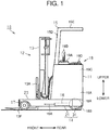
FIG. 1 is a side view of a reach truck according to one embodiment of the present invention; -
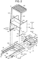
FIG. 2 is an exploded perspective view of a straddle arm assembly, a rear frame assembly, and an upper frame assembly of the reach truck ofFIG. 1 ; -
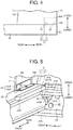
FIG. 3A is a perspective view of a part of the reach truck ofFIG. 1 as viewed from an angle; -
FIG. 3B is a perspective view of the part of the reach truck ofFIG. 1 as viewed from another angle; -
FIG. 4 is a schematic side view showing a part of the reach truck; and -
FIG. 5 is a perspective view showing a part of a reach truck according to another embodiment of the present invention. - The following will describe an embodiment of a reach truck according to the present invention with reference to
FIGS. 1 to 4 . In the following description, the terms such as front, rear, right, left, upper, lower and the like are used to refer to the positions or directions as viewed from an operator of the reach truck facing in the forward traveling direction of the reach truck. - Referring now to
FIG. 1 , there is shown areach truck 10 having avehicle body 11. Thereach truck 10 includes aloading equipment 12 located in the front of thevehicle body 11. Theloading equipment 12 includes amast assembly 13 that is disposed vertically in the front part of thevehicle body 11, and a pair of right andleft forks 13F mounted to themast assembly 13 through alift bracket 13A. Theforks 13F correspond to the loading implement of the present invention. Theforks 13F are movable in the vertical direction relative to themast assembly 13 via thelift bracket 13A. - The
vehicle body 11 of thereach truck 10 includes abase frame assembly 14 that forms a base of thevehicle body 11 and anupper frame assembly 15 that is disposed on thebase frame assembly 14 and forms a body portion of thevehicle body 11. Thebase frame assembly 14 includes astraddle arm assembly 21 having a pair of right andleft straddle arms 20 that guides themast assembly 13 to move forward or rearward or in the longitudinal direction of thestraddle arm assembly 21. Thebase frame assembly 14 further includes arear frame assembly 31 that is joined to the rear end of thestraddle arm assembly 21 on the side opposite to thestraddle arms 20. Thestraddle arms 20 have a square columnar shape extending forward. - A pair of reach cylinders 16 (hydraulic cylinders) is disposed in the lower part of the
vehicle body 11. Eachreach cylinder 16 has apiston rod 16A joined to themast assembly 13. Themast assembly 13 is movable forward and rearward along thestraddle arms 20 for a distance within a specified stroke length during the extending and retracting motion of thepiston rods 16A of thereach cylinders 16. - Each
straddle arm 20 has in a lower part of the leading end thereof a drivenwheel 17. Thevehicle body 11 has in the lower rear part thereof asteerable drive wheel 18A and acaster wheel 18B. Thesteerable drive wheel 18A is disposed at a position offset leftward from the width center of thevehicle body 11 as seen in the forward moving direction of thereach truck 10 and thecaster wheel 18B is spaced rightward at a predetermined distance away from thesteerable drive wheel 18A in such a manner that thesteerable drive wheel 18A and thecaster wheel 18B are provided in a pair in the lateral direction of thevehicle body 11. - An operator's
compartment 19 or a cabin of a stand-up type is provided in the right rear part of thevehicle body 11. Aninstrumental panel 19A is disposed in the front part of the operator'scompartment 19 of thevehicle body 11. Theinstrumental panel 19A has anoperation control lever 19B for controlling the load-handling operation and the like. An uprightaccommodating box 19C is provided on the left side of the operator'scompartment 19 and asteering wheel 19D is provided at the top of theaccommodating box 19C. - As shown in
FIG. 2 , theupper frame assembly 15 includes a pair of right andleft side members 15A that forms the right and left side portions of thevehicle body 11 and a laterally-extending vertical connectingmember 15B through which theside members 15A are connected to each other. The connectingmember 15B is connected to theside members 15A approximately at the respective longitudinal centers thereof. Ahorizontal partition member 15C is provided on the front side of the connectingmember 15B, extending frontward from a position of the connectingmember 15B that is above the center of the connectingmember 15B as measured in the vertical direction thereof. Thepartition member 15C is joined at opposite lateral sides thereof to theside members 15A. Theupper frame assembly 15 and thepartition member 15C cooperate to form a space for accommodating therein a battery (not shown) below thepartition member 15C. A pair of L-shaped pillars 15D is provided at the opposite front corners of thepartition member 15C, extending upward from the upper surface thereof and anoverhead guard 15E is mounted to the top of thepillars 15D. - A
bracket 15F having an L-shaped cross section is fixed to the inner surface of therespective side members 15A at bottom positions thereof that are frontward of the connectingmember 15B. Eachbracket 15F includes afirst bracket portion 151F extending upward along the inner surface of theside members 15A and asecond bracket portion 152F extending inward of theside members 15A at a right angle relative to the first bracket portion 151 F. The first andsecond bracket portions vehicle body 11. Eachbracket 15F is fixed at thefirst bracket portion 151F thereof to the inner surface of itscorresponding side member 15A by welding. Thesecond bracket portion 152F of eachbracket 15F has therethrough twobolt holes 15H that are spaced at a distance in the longitudinal direction. - Each
straddle arm 20 includes aguide rail 20A having a C-shaped cross section and extending on the inner side of thestraddle arm 20 in the longitudinal direction of thevehicle body 11 so that themast assembly 13 is guided to move forward and rearward. Eachstraddle arm 20 has in the upper member thereof two internally-threadedholes 20H spaced in the longitudinal direction at the same distance between twobolt holes 15H in thesecond bracket portion 152F of thebracket 15F. - The
straddle arm assembly 21 includes a laterally-extending first connectingmember 21A through which thestraddle arms 20 are connected to each other. The first connectingmember 21A is connected at the opposite lateral sides thereof to the bottom surfaces of thestraddle arms 20 at portions thereof adjacent to the rear ends of thestraddle arms 20 to thereby connect thestraddle arms 20 to each other. - Two internally-threaded
holes 21 H are formed through the first connectingmember 21A at positions adjacent to the lateral side edges thereof and inward of thestraddle arms 20. - As shown in
FIGS. 3A and 3B , thestraddle arm assembly 21 further includes avertical member 22 that continues from the rear end of the first connectingmember 21A and extends upward. Thevertical member 22 extends laterally between thestraddle arms 20. - The
straddle arm assembly 21 further includes a second connectingmember 21 B that is disposed so as to face the first connectingmember 21A from above and through which the pair ofstraddle arms 20 are connected to each other. The first connectingmember 21A and the second connectingmember 21 B correspond to the connecting member of the present invention. The second connectingmember 21 B is connected at the opposite lateral sides thereof to the upper parts of thestraddle arms 20 to thereby connect the pair ofstraddle arms 20 to each other. - As shown in
FIG. 2 , therear frame assembly 31 has a rough rectangular shape in a plan view. Therear frame assembly 31 includes awide frame member 32 forming a rear part of therear frame assembly 31 and having a width corresponding to the distance between the outer surfaces of the pair ofstraddle arms 20, and anarrow frame member 33 continuing from thewide frame member 32 and having a width that is smaller than the width of thewide frame member 32. As shown inFIG. 2 , thewide frame member 32 has at the rear thereof curved corners. Thenarrow frame member 33 that forms a front part of therear frame assembly 31 is located adjacent to thestraddle arm assembly 21. Thenarrow frame member 33 includes avertical member 33A that extends vertically and laterally and disposed so as to face thevertical member 22 of thestraddle arm assembly 21. - The
vertical member 33A of thenarrow frame member 33 has on thefront surface 33B thereof facing the straddle arm assembly 21 a pair of firstjoint members 31A extending toward thestraddle arm assembly 21. Each firstjoint member 31A includes ahorizontal arm member 311A that extends perpendicularly from thefront surface 33B of thevertical member 33A. Eachhorizontal arm member 311A is connected to thefront surface 33B of thevertical member 33A in such a manner that the plane thereof extends in the lateral direction of thevehicle body 11. Furthermore, each firstjoint member 31A includes arib 312A that is connected to thefront surface 33B of thevertical member 33A and an upper surface of thehorizontal arm member 311A. The firstjoint members 31A or thehorizontal arm members 311A are reinforced by providing theribs 312A. Eachhorizontal arm member 311A has abolt hole 31 H at a position adjacent to the tip end thereof. - Two
bolt holes 33H are formed through thevertical member 33A at positions inward of each firstjoint member 31A. The twoholes 33H are spaced at a specified distance in the direction intersecting the lateral direction of thevehicle body 11. - The
wide frame member 32 of therear frame assembly 31 has an extendedupstanding member 32A that is formed along one of the rear curved corners and extending upward beyond the upper edge of thewide frame member 32. The extendedupstanding member 32A has a thickness that is smaller than the thickness of the side and rear walls of therear frame assembly 31. The extendedupstanding member 32A is formed such that the outer surface thereof is located inward of the outer surface of thewide frame member 32 and that the inner surface of the extendedupstanding member 32A is in flush with the inner surface of thewide frame member 32. - The
rear frame assembly 31 has therein the aforementionedsteerable drive wheel 18A, thecaster wheel 18B, and a drive unit 35 (schematically illustrated by a two-dot chain line inFIG. 2 ) including an electric motor and a brake device that drives and brakes thesteerable drive wheel 18A. - As shown in
FIGS. 3A and 3B , thevertical member 22 of thestraddle arm assembly 21 are cut out to form insertion holes 21 D through which the firstjoint members 31A may be inserted. Each firstjoint member 31A is passed through itscorresponding insertion hole 21 D and placed on the upper surface of the first connectingmember 21A. In the state in which the firstjoint members 31A passed through the insertion holes 21 D and thefront surface 33B of thevertical member 33A of therear frame assembly 31 abuts thevertical member 22 of thestraddle arm assembly 21, the bolt holes 31 H of thehorizontal arm members 311A and the internally-threadedholes 21 H of the first connectingmember 21A are aligned with each other. Then, the firstjoint members 31A and the first connectingmember 21A are set in contact with and joined to each other bybolts 41 inserted and tightened in the bolt holes 31 H and the internally-threadedholes 21 H. Thebolts 41 correspond to the fastening member of the present invention. The firstjoint members 31A that are joined to thestraddle arm assembly 21 by thebolts 41 correspond to the joint member of the present invention. - The
vertical member 33A of therear frame assembly 31 and thevertical member 22 of thestraddle arm assembly 21 are set in contact with and joined to each other at theholes 33H by thebolts 42. Thebolts 42 correspond to the fastening member of the present invention. Thevertical member 33A that is set in contact with and joined to thevertical member 22 by thebolts 42 in the longitudinal direction serves as the second joint member of the present invention that is connected to thestraddle arm assembly 21. - The pair of
side members 15A of theupper frame assembly 15 is placed on the upper surfaces of therespective straddle arms 20 and also on the upper edge of thewide frame member 32 of therear frame assembly 31. Thus theupper frame assembly 15 is placed on thebase frame assembly 14. In this state, the bolt holes 15H of eachbracket 15F are aligned with theholes 20H of thecorresponding straddle arm 20. Theupper frame assembly 15 is joined by thebolts 43 to thestraddle arm assembly 21 at the bolt holes 15H and theholes 20H that are aligned with each other. Theupper frame assembly 15 and thestraddle arm assembly 21 are joined together in the vertical direction by thebolts 43. - As illustrated in
FIG. 4 , with theside members 15A mounted in place on the upper surfaces of thestraddle arms 20 and the upper edge of thewide frame member 32 of therear frame assembly 31, the extendedupstanding member 32A is located inward of theside members 15A. Two threadedholes 15J are formed through each of theside members 15A of theupper frame assembly 15 which overlaps with the extendedupstanding member 32A. Theupper frame assembly 15 is joined to therear frame assembly 31 by twobolts 44 screwed in theholes 15J. Thebolts 44 correspond to the fastening member of the present invention. Theupper frame assembly 15 is joined to therear frame assembly 31 by thebolts 44 on the lateral sides thereof. - The following will describe the function of the present embodiment.
- In a reach truck such as 10 of the present embodiment of the present invention, various designs, such as the distance between the
straddle arms 20, the length of thestraddle arms 20, and the shape of thestraddle arms 20, are modified appropriately depending on the application of the reach truck. As a result, there has been a number of reach trucks of different specifications for straddle arm assemblies. However, the drive unit such as 35 accommodated in therear frame assembly 31 is often common for various reach trucks. Therefore, the design of the rear frame assembly for accommodating therein the drive unit need not be modified for each different reach truck. - According to the present embodiment, the
rear frame assembly 31 has the firstjoint members 31A and thevertical member 33A that serve as the joint member and are joined to thestraddle arm assembly 21 by thebolts straddle arm assembly 21 having different dimensional specifications may be compatibly joined to therear frame assembly 31 by joining the firstjoint members 31A of therear frame assembly 31 and thevertical member 33A to thestraddle arm assembly 21 by thebolts - By fastening the first
joint members 31A of therear frame assembly 31 and the first connectingmember 21A of thestraddle arm assembly 21 by means of thebolts 41, thestraddle arm assembly 21 and therear frame assembly 31 are positioned properly relative to each other in the vertical direction. Therefore, for example, relative displacement in the vertical direction between thestraddle arm assembly 21 and therear frame assembly 31 which may occur while thereach truck 10 is traveling may be prevented. Furthermore, in thereach truck 10 in which the firstjoint members 31A and the first connectingmember 21A are set in contact with and joined to each other by thebolts 41 in the vertical direction, the force acting in the vertical direction due to the vertical vibration of thereach truck 10 is received by the contact portions between the firstjoint members 31 A and the first connectingmember 21 A. - The
straddle arm assembly 21 and therear frame assembly 31 are positioned relative to each other in the longitudinal direction of thevehicle body 11 with thevertical member 33A and thevertical member 22 set in contact with and joined to each other by thebolts 42 in the longitudinal direction. Therefore, for example, relative displacement in the longitudinal direction between thestraddle arm assembly 21 and therear frame assembly 31 which may occur while thereach truck 10 is traveling may be prevented. Furthermore, thevertical member 33A of therear frame assembly 31 and thevertical member 22 of thestraddle arm assembly 21 are set in contact with and joined to each other by thebolts 42 in the longitudinal direction. Therefore, the force acting in the longitudinal direction due to the longitudinal vibration of thereach truck 10 is received by the contact portion between thevertical member 33A and thevertical member 22. - Since the
straddle arms 20 are connected to each other through the first and second connectingmembers straddle arms 20 in the direction separating from each other is prevented. - According to the above embodiment, the following effects are obtained.
- (1) In the
reach truck 10 of the present embodiment in which therear frame assembly 31 has the firstjoint members 31A and thevertical member 33A that are joined to thestraddle arm assembly 21 by thebolts rear frame assembly 31 may be joined to thestraddle arm assembly 21 of various sizes and types merely by joining the firstjoint members 31A of therear frame assembly 31 and thevertical member 33A to thestraddle arm assembly 21 by thebolts - (2) In the
reach truck 10 of the present embodiment in which the firstjoint members 31A of therear frame assembly 31 is set in contact with and joined to the first connectingmember 21A by thebolts 41 in the vertical direction, thestraddle arm assembly 21 and therear frame assembly 31 are positioned correctly relative to each other in the vertical direction. Therefore, for example, relative displacement in the vertical direction between thestraddle arm assembly 21 and therear frame assembly 31 which may occur while thereach truck 10 is traveling may be prevented. Furthermore, in thereach truck 10 in which the firstjoint members 31A and the first connectingmember 21A are set in contact with and joined to each other by thebolts 41 in the vertical direction, the force acting in the vertical direction due to vertical vibration of thereach truck 10 is received by the contact portions between the firstjoint members 31 A and the first connectingmember 21 A. - (3) The
rear frame assembly 31 in which thevertical member 33A of therear frame assembly 31 is set in contact with and joined to thevertical member 22 by thebolts 42 in the longitudinal direction, thestraddle arm assembly 21 and therear frame assembly 31 are positioned correctly relative to each other in the longitudinal direction by thevertical member 33A and thevertical member 22 that are joined together by thebolts 42 in the longitudinal direction. Therefore, for example, relative displacement in the longitudinal direction between thestraddle arm assembly 21 and therear frame assembly 31 which may occur while thereach truck 10 is traveling may be prevented. Furthermore, thevertical member 33A of therear frame assembly 31 and thevertical member 22 of thestraddle arm assembly 21 are set in contact with and joined to each other in the longitudinal direction by the fastening members. Therefore, the force acting in the longitudinal direction due to the longitudinal vibration of thereach truck 10 is received by the contact portion between thevertical member 33A and thevertical member 22. - (4) The
upper frame assembly 15 is joined to thestraddle arm assembly 21 and therear frame assembly 31 by thebolts upper frame assembly 15 is joined by welding to at least one of thestraddle arm assembly 21 and therear frame assembly 31 so as to form a module component for a reach truck. In such a case, if a change is made to the design of thestraddle arm assembly 21 or therear frame assembly 31 for adaptation to a different model, the change may inevitably require a change in the design of theupper frame assembly 15. The configuration of the present embodiment in which theupper frame assembly 15 is joined to thestraddle arm assembly 21 and therear frame assembly 31 by thebolts upper frame assembly 15 for each different model of thereach truck 10, and theupper frame assembly 15 can be used commonly among different models, which helps to facilitate the manufacturing of thereach truck 10. - (5) In the present embodiment in which the first connecting
member 21A and the second connectingmember 21 B of thestraddle arm assembly 21 connect the pair ofstraddle arms 20 to each other, the first and second connectingmembers straddle arms 20 from being displaced or detached away from each other. Therefore, it is easy to maintain the distance between thestraddle arms 20. - (6) In the case that the
straddle arm assembly 21 and therear frame assembly 31 are joined to each other, for example, by welding, thedrive unit 35 needs to be mounted in therear frame assembly 31 only after the welding is completed, which restricts the assembling procedure of thereach truck 10. However, the present embodiment in which therear frame assembly 31 accommodating therein thedrive unit 35 is joined to thestraddle arm assembly 21 does not suffer from such restriction. - (7) In the case that the
straddle arm assembly 21 and therear frame assembly 31 are joined to each other, for example, by welding to thereby form a module component, painting of such modularized component requires a large painting facility. However, according to the present embodiment, thestraddle arm assembly 21 and therear frame assembly 31 may be joined together after being painted individually and separately. Therefore, no such large coating facility is required and an increase in the cost and investment for the facility as a whole is prevented. - The above embodiment may be modified variously as followings:
- As shown in
FIG. 5 , it may be so configured that the firstjoint members 31 A and the second connectingmember 21 B are set in contact with and joined to each other by thebolts 41 in the vertical direction. In this case, the paired firstjoint members 31A extend frontward from the upper lateral opposite corners of thefront surface 33B of thevertical member 33A facing thestraddle arm assembly 21. Furthermore, the upper lateral corners of thevertical member 22 of thestraddle arm assembly 21 are cut out to form the insertion holes 21 D for allowing the firstjoint members 31 A to pass therethrough. - In the above embodiment, the
straddle arm assembly 21 and therear frame assembly 31 may be joined to each other by joining the firstjoint members 31 A and the first connectingmember 21 A together by thebolts 41. Thevertical member 33A of therear frame assembly 31 and thevertical member 22 of thestraddle arm assembly 21 need not be joined together by thebolts 42. In other words, joining between thestraddle arm assembly 21 and therear frame assembly 31 may be performed in the vertical direction only. - Alternatively, in the above embodiment, the
straddle arm assembly 21 and therear frame assembly 31 may be joined by joining thevertical member 33A and thevertical member 22 by thebolts 42, and the firstjoint members 31A and the first connectingmember 21 A need not be joined by thebolts 41. Specifically, joining between thestraddle arm assembly 21 and therear frame assembly 31 may be performed in the longitudinal direction only. - In the above embodiment, the first
joint members 31A of therear frame assembly 31 and the first connectingmember 21A of thestraddle arm assembly 21 are joined to each other by thebolts 41 in the vertical direction. However, the firstjoint members 31A may be joined at any portions of thestraddle arm assembly 21. - In the above embodiment, the
vertical member 33A and thevertical member 22 of thestraddle arm assembly 21 are joined to each other in the longitudinal direction by thebolts 42. However, thevertical member 33A may be joined at any other portions in thestraddle arm assembly 21. - In the above embodiment, the second connecting
member 21 B may not be used. - In the above embodiment, the number of the first
joint members 31A is not particularly limited. - In the above embodiment, the number of the
bolts - In the above embodiment, the fastening members are not particularly limited to the bolts such as 41, 42, 43, and 44. For example, press-fit pins may be used as the fastening members.
- In the above embodiment, the
upper frame assembly 15 may be joined to therear frame assembly 31 by welding so as to form a module component. - In the above embodiment, power cylinders using an electric motor may be used as the
reach cylinders 16 as long as such power cylinders are able to move themast assembly 13 in the longitudinal direction along the pair ofstraddle arms 20. - In the above embodiment, the
reach truck 10 may be driven to travel by an engine or a hybrid engine that uses an engine and a traction motor. - In the above embodiment, the
reach truck 10 may be an order picker reach truck having a platform that is movable up and down with theloading equipment 12 while carrying an operator and a load or an unmanned reach truck that does not require an operator to be present thereon.
Claims (5)
- A reach truck (10) comprising:a vehicle body (11);a mast assembly (13) that is disposed in a front part of the vehicle body (11) and has a loading implement (12);a straddle arm assembly (21) having a pair of right and left straddle arms (20) that guides the mast assembly (13) to move in a longitudinal direction of the straddle arm assembly (21); anda rear frame assembly (31) that is joined to a rear end of the straddle arm assembly (21) and accommodates therein a drive unit (35), characterized in thatthe rear frame assembly (31) includes a joint member (31A, 33A) through which the rear frame assembly (31) and the straddle arm assembly (21) are joined to each other by a fastening member (41, 42, 43, 44).
- The reach truck (10) according to claim 1, characterized in that
the joint member (31 A, 33A) includes a first joint member (31 A), and
the straddle arm assembly (21) and the rear frame assembly (31) are set in contact with and joined to each other by the fastening member (41, 42, 43, 44) in a vertical direction. - The reach truck according to claim 1 or 2, characterized in that
the joint member (31 A, 33A) includes a second joint member (33A), and
the straddle arm assembly (21) and the rear frame assembly (31) are set in contact with and joined to each other by the fastening member (41, 42, 43, 44) in the longitudinal direction. - The reach truck (10) according to any one of claims 1 to 3, characterized in that
the reach truck (10) further includes an upper frame assembly (15) that forms a body portion of the vehicle body (11), and
the upper frame assembly (15) is joined to at least one of the straddle arm assembly (21) and the rear frame assembly (31) by the fastening member (41, 42, 43, 44). - The reach truck (10) according to any one of claims 1 to 4, characterized in that
the straddle arm assembly (21) includes a connecting member (21A, 21 B) through which the straddle arms (20) are connected to each other.
Applications Claiming Priority (1)
| Application Number | Priority Date | Filing Date | Title |
|---|---|---|---|
| JP2015239440A JP6350501B2 (en) | 2015-12-08 | 2015-12-08 | Reach type forklift |
Publications (2)
| Publication Number | Publication Date |
|---|---|
| EP3178774A1 true EP3178774A1 (en) | 2017-06-14 |
| EP3178774B1 EP3178774B1 (en) | 2018-08-15 |
Family
ID=57394429
Family Applications (1)
| Application Number | Title | Priority Date | Filing Date |
|---|---|---|---|
| EP16200298.4A Active EP3178774B1 (en) | 2015-12-08 | 2016-11-23 | Reach truck |
Country Status (6)
| Country | Link |
|---|---|
| EP (1) | EP3178774B1 (en) |
| JP (1) | JP6350501B2 (en) |
| KR (1) | KR20170067651A (en) |
| CN (1) | CN106882735B (en) |
| AU (1) | AU2016259431B2 (en) |
| TW (1) | TWI622551B (en) |
Families Citing this family (2)
| Publication number | Priority date | Publication date | Assignee | Title |
|---|---|---|---|---|
| DE102018101539A1 (en) * | 2018-01-24 | 2019-07-25 | Jungheinrich Aktiengesellschaft | Basic frame for a reach truck |
| CN109334748B (en) * | 2018-10-31 | 2020-01-21 | 安徽鑫泰钻石有限公司 | Transfer device of diamond containing box |
Citations (4)
| Publication number | Priority date | Publication date | Assignee | Title |
|---|---|---|---|---|
| GB2110620A (en) * | 1981-12-03 | 1983-06-22 | Clark Equipment Co | Industrial vehicle and adjustable guide roller assembly therefor |
| JP2004338856A (en) * | 2003-05-14 | 2004-12-02 | Nippon Yusoki Co Ltd | Reach forklift truck |
| EP1905726A1 (en) * | 2006-09-28 | 2008-04-02 | BT Industries Aktiebolag | Lift truck with a support leg arrangement |
| JP2008221981A (en) | 2007-03-12 | 2008-09-25 | Toyota Industries Corp | Suspension apparatus for use in industrial vehicle and reach fork lift |
Family Cites Families (19)
| Publication number | Priority date | Publication date | Assignee | Title |
|---|---|---|---|---|
| JPS5244511U (en) * | 1975-09-23 | 1977-03-29 | ||
| JPS59102797A (en) * | 1982-11-30 | 1984-06-13 | 株式会社豊田自動織機製作所 | Reach type forklift truck |
| JPS59143873U (en) * | 1983-03-17 | 1984-09-26 | 小松フオ−クリフト株式会社 | Body of standing reach oaklift |
| JPS60145972U (en) * | 1984-03-09 | 1985-09-27 | 小松フオ−クリフト株式会社 | Cargo handling vehicle body equipment |
| JPH079913Y2 (en) * | 1989-11-24 | 1995-03-08 | 小松フォークリフト株式会社 | Reach forklift frame structure |
| KR0139857B1 (en) * | 1995-12-30 | 1999-04-15 | 석진철 | Body of electric reach forklift |
| TW325051U (en) * | 1996-06-13 | 1998-01-11 | Lift Tech Corp | Improved self-driven portion of electromotive forklift |
| JPH1036089A (en) * | 1996-07-23 | 1998-02-10 | Nippon Yusoki Co Ltd | Cargo vehicle |
| KR200168763Y1 (en) * | 1997-12-30 | 2000-03-02 | 추호석 | Arrangement for mounting overhead guard in reach type forklift truck |
| KR200355088Y1 (en) * | 1998-12-22 | 2004-09-16 | 대우종합기계 주식회사 | Frame Assembly of Reach Type Forklift |
| JP3806582B2 (en) * | 2000-06-27 | 2006-08-09 | Tcm株式会社 | Battery powered forklift |
| EP1304279A1 (en) * | 2000-07-14 | 2003-04-23 | TCM Corporation | Working vehicle with traversing system |
| DE10228631A1 (en) * | 2002-06-26 | 2004-01-22 | Still Wagner Gmbh & Co. Kg | Industrial truck with a damped driver's seat |
| JP2005162378A (en) * | 2003-12-02 | 2005-06-23 | Toyota Industries Corp | Reach type fork lift and mounting method for mast assembly on reach leg |
| JP5066872B2 (en) * | 2006-09-08 | 2012-11-07 | 株式会社豊田自動織機 | Frame structure of counterbalance type cargo handling vehicle |
| CN201587791U (en) * | 2009-11-16 | 2010-09-22 | 三一集团有限公司 | Container spreader with top box mechanism and stacker with the container spreader |
| CN101966973B (en) * | 2010-09-28 | 2012-12-05 | 三一集团有限公司 | Stacking machine and lifting appliance thereof |
| DE102013004435A1 (en) * | 2013-03-15 | 2014-09-18 | Jungheinrich Aktiengesellschaft | Mast for a truck |
| CN204298015U (en) * | 2014-09-29 | 2015-04-29 | 奇瑞重工股份有限公司 | Fork truck storage battery install structure and there is its reach truck |
-
2015
- 2015-12-08 JP JP2015239440A patent/JP6350501B2/en active Active
-
2016
- 2016-11-18 AU AU2016259431A patent/AU2016259431B2/en active Active
- 2016-11-23 EP EP16200298.4A patent/EP3178774B1/en active Active
- 2016-12-01 TW TW105139615A patent/TWI622551B/en active
- 2016-12-02 KR KR1020160163247A patent/KR20170067651A/en not_active Ceased
- 2016-12-07 CN CN201611120820.XA patent/CN106882735B/en active Active
Patent Citations (4)
| Publication number | Priority date | Publication date | Assignee | Title |
|---|---|---|---|---|
| GB2110620A (en) * | 1981-12-03 | 1983-06-22 | Clark Equipment Co | Industrial vehicle and adjustable guide roller assembly therefor |
| JP2004338856A (en) * | 2003-05-14 | 2004-12-02 | Nippon Yusoki Co Ltd | Reach forklift truck |
| EP1905726A1 (en) * | 2006-09-28 | 2008-04-02 | BT Industries Aktiebolag | Lift truck with a support leg arrangement |
| JP2008221981A (en) | 2007-03-12 | 2008-09-25 | Toyota Industries Corp | Suspension apparatus for use in industrial vehicle and reach fork lift |
Also Published As
| Publication number | Publication date |
|---|---|
| CN106882735A (en) | 2017-06-23 |
| JP2017105571A (en) | 2017-06-15 |
| AU2016259431A1 (en) | 2017-06-22 |
| JP6350501B2 (en) | 2018-07-04 |
| AU2016259431B2 (en) | 2018-08-09 |
| CN106882735B (en) | 2019-07-19 |
| TW201726533A (en) | 2017-08-01 |
| EP3178774B1 (en) | 2018-08-15 |
| TWI622551B (en) | 2018-05-01 |
| KR20170067651A (en) | 2017-06-16 |
Similar Documents
| Publication | Publication Date | Title |
|---|---|---|
| JP5597681B2 (en) | Car body rear structure | |
| CN106985650B (en) | Mounting structure and method for automobile power battery | |
| CN112292278A (en) | Battery pack supporting device for vehicle | |
| US12145433B2 (en) | Vehicle substructure for an at least semi-electrically driven motor vehicle | |
| US10046957B2 (en) | Industrial vehicle | |
| EP3178774B1 (en) | Reach truck | |
| CN115989172A (en) | Energy storage for electrically driven cars - Underbody components | |
| US7610977B2 (en) | Lift truck having hydraulically separate main frame and power unit assembly | |
| CN202518201U (en) | Installation structure of electronic control unit and automobile body of automobile | |
| CN212401418U (en) | Unmanned vehicle with separable functional modules | |
| DE10316403B4 (en) | Reach truck | |
| CN103507799A (en) | Supporting structure for reserve tank | |
| EP3053871B1 (en) | Industrial vehicle | |
| JP7367594B2 (en) | Battery car body grounding structure and battery car body grounding method | |
| EP2915771B1 (en) | Forklift head-guard structure | |
| CN205769574U (en) | A kind of chassis system of multifunctional vehicle | |
| EP3053813B1 (en) | Towing tractor | |
| JP3806582B2 (en) | Battery powered forklift | |
| JP5080929B2 (en) | Work vehicle | |
| EP2457867B1 (en) | Industrial truck, in particular forklift, with a hybrid drive | |
| JP5872945B2 (en) | forklift | |
| KR102743572B1 (en) | Integral Trailing Arm Mount Bracket for Purpose-Based Vehicles | |
| JP7452365B2 (en) | industrial vehicle | |
| JP2020083267A (en) | Vehicle battery pack support device and manufacturing method of the same | |
| JP2018002339A (en) | Cargo handling work vehicle |
Legal Events
| Date | Code | Title | Description |
|---|---|---|---|
| PUAI | Public reference made under article 153(3) epc to a published international application that has entered the european phase |
Free format text: ORIGINAL CODE: 0009012 |
|
| 17P | Request for examination filed |
Effective date: 20161123 |
|
| AK | Designated contracting states |
Kind code of ref document: A1 Designated state(s): AL AT BE BG CH CY CZ DE DK EE ES FI FR GB GR HR HU IE IS IT LI LT LU LV MC MK MT NL NO PL PT RO RS SE SI SK SM TR |
|
| AX | Request for extension of the european patent |
Extension state: BA ME |
|
| GRAP | Despatch of communication of intention to grant a patent |
Free format text: ORIGINAL CODE: EPIDOSNIGR1 |
|
| RIC1 | Information provided on ipc code assigned before grant |
Ipc: B66F 9/10 20060101ALI20180131BHEP Ipc: B66F 9/075 20060101AFI20180131BHEP |
|
| INTG | Intention to grant announced |
Effective date: 20180220 |
|
| GRAS | Grant fee paid |
Free format text: ORIGINAL CODE: EPIDOSNIGR3 |
|
| GRAA | (expected) grant |
Free format text: ORIGINAL CODE: 0009210 |
|
| RIN1 | Information on inventor provided before grant (corrected) |
Inventor name: UMEZAWA, RYOSUKE Inventor name: URAYAMA, KOJI Inventor name: OTSUKA, HARUHIKO Inventor name: KAMIYA, KAZUSHI Inventor name: KAIZAWA, SHINJI Inventor name: KURODA, HIROMITSU |
|
| AK | Designated contracting states |
Kind code of ref document: B1 Designated state(s): AL AT BE BG CH CY CZ DE DK EE ES FI FR GB GR HR HU IE IS IT LI LT LU LV MC MK MT NL NO PL PT RO RS SE SI SK SM TR |
|
| REG | Reference to a national code |
Ref country code: CH Ref legal event code: EP Ref country code: GB Ref legal event code: FG4D Ref country code: AT Ref legal event code: REF Ref document number: 1029503 Country of ref document: AT Kind code of ref document: T Effective date: 20180815 |
|
| REG | Reference to a national code |
Ref country code: IE Ref legal event code: FG4D |
|
| REG | Reference to a national code |
Ref country code: DE Ref legal event code: R096 Ref document number: 602016004789 Country of ref document: DE |
|
| REG | Reference to a national code |
Ref country code: NL Ref legal event code: MP Effective date: 20180815 |
|
| REG | Reference to a national code |
Ref country code: LT Ref legal event code: MG4D |
|
| REG | Reference to a national code |
Ref country code: AT Ref legal event code: MK05 Ref document number: 1029503 Country of ref document: AT Kind code of ref document: T Effective date: 20180815 |
|
| PG25 | Lapsed in a contracting state [announced via postgrant information from national office to epo] |
Ref country code: NO Free format text: LAPSE BECAUSE OF FAILURE TO SUBMIT A TRANSLATION OF THE DESCRIPTION OR TO PAY THE FEE WITHIN THE PRESCRIBED TIME-LIMIT Effective date: 20181115 Ref country code: GR Free format text: LAPSE BECAUSE OF FAILURE TO SUBMIT A TRANSLATION OF THE DESCRIPTION OR TO PAY THE FEE WITHIN THE PRESCRIBED TIME-LIMIT Effective date: 20181116 Ref country code: SE Free format text: LAPSE BECAUSE OF FAILURE TO SUBMIT A TRANSLATION OF THE DESCRIPTION OR TO PAY THE FEE WITHIN THE PRESCRIBED TIME-LIMIT Effective date: 20180815 Ref country code: AT Free format text: LAPSE BECAUSE OF FAILURE TO SUBMIT A TRANSLATION OF THE DESCRIPTION OR TO PAY THE FEE WITHIN THE PRESCRIBED TIME-LIMIT Effective date: 20180815 Ref country code: LT Free format text: LAPSE BECAUSE OF FAILURE TO SUBMIT A TRANSLATION OF THE DESCRIPTION OR TO PAY THE FEE WITHIN THE PRESCRIBED TIME-LIMIT Effective date: 20180815 Ref country code: NL Free format text: LAPSE BECAUSE OF FAILURE TO SUBMIT A TRANSLATION OF THE DESCRIPTION OR TO PAY THE FEE WITHIN THE PRESCRIBED TIME-LIMIT Effective date: 20180815 Ref country code: BG Free format text: LAPSE BECAUSE OF FAILURE TO SUBMIT A TRANSLATION OF THE DESCRIPTION OR TO PAY THE FEE WITHIN THE PRESCRIBED TIME-LIMIT Effective date: 20181115 Ref country code: IS Free format text: LAPSE BECAUSE OF FAILURE TO SUBMIT A TRANSLATION OF THE DESCRIPTION OR TO PAY THE FEE WITHIN THE PRESCRIBED TIME-LIMIT Effective date: 20181215 Ref country code: RS Free format text: LAPSE BECAUSE OF FAILURE TO SUBMIT A TRANSLATION OF THE DESCRIPTION OR TO PAY THE FEE WITHIN THE PRESCRIBED TIME-LIMIT Effective date: 20180815 Ref country code: FI Free format text: LAPSE BECAUSE OF FAILURE TO SUBMIT A TRANSLATION OF THE DESCRIPTION OR TO PAY THE FEE WITHIN THE PRESCRIBED TIME-LIMIT Effective date: 20180815 |
|
| PG25 | Lapsed in a contracting state [announced via postgrant information from national office to epo] |
Ref country code: AL Free format text: LAPSE BECAUSE OF FAILURE TO SUBMIT A TRANSLATION OF THE DESCRIPTION OR TO PAY THE FEE WITHIN THE PRESCRIBED TIME-LIMIT Effective date: 20180815 Ref country code: HR Free format text: LAPSE BECAUSE OF FAILURE TO SUBMIT A TRANSLATION OF THE DESCRIPTION OR TO PAY THE FEE WITHIN THE PRESCRIBED TIME-LIMIT Effective date: 20180815 Ref country code: LV Free format text: LAPSE BECAUSE OF FAILURE TO SUBMIT A TRANSLATION OF THE DESCRIPTION OR TO PAY THE FEE WITHIN THE PRESCRIBED TIME-LIMIT Effective date: 20180815 |
|
| PG25 | Lapsed in a contracting state [announced via postgrant information from national office to epo] |
Ref country code: PL Free format text: LAPSE BECAUSE OF FAILURE TO SUBMIT A TRANSLATION OF THE DESCRIPTION OR TO PAY THE FEE WITHIN THE PRESCRIBED TIME-LIMIT Effective date: 20180815 Ref country code: EE Free format text: LAPSE BECAUSE OF FAILURE TO SUBMIT A TRANSLATION OF THE DESCRIPTION OR TO PAY THE FEE WITHIN THE PRESCRIBED TIME-LIMIT Effective date: 20180815 Ref country code: CZ Free format text: LAPSE BECAUSE OF FAILURE TO SUBMIT A TRANSLATION OF THE DESCRIPTION OR TO PAY THE FEE WITHIN THE PRESCRIBED TIME-LIMIT Effective date: 20180815 Ref country code: RO Free format text: LAPSE BECAUSE OF FAILURE TO SUBMIT A TRANSLATION OF THE DESCRIPTION OR TO PAY THE FEE WITHIN THE PRESCRIBED TIME-LIMIT Effective date: 20180815 Ref country code: ES Free format text: LAPSE BECAUSE OF FAILURE TO SUBMIT A TRANSLATION OF THE DESCRIPTION OR TO PAY THE FEE WITHIN THE PRESCRIBED TIME-LIMIT Effective date: 20180815 |
|
| REG | Reference to a national code |
Ref country code: DE Ref legal event code: R097 Ref document number: 602016004789 Country of ref document: DE |
|
| PG25 | Lapsed in a contracting state [announced via postgrant information from national office to epo] |
Ref country code: SK Free format text: LAPSE BECAUSE OF FAILURE TO SUBMIT A TRANSLATION OF THE DESCRIPTION OR TO PAY THE FEE WITHIN THE PRESCRIBED TIME-LIMIT Effective date: 20180815 Ref country code: DK Free format text: LAPSE BECAUSE OF FAILURE TO SUBMIT A TRANSLATION OF THE DESCRIPTION OR TO PAY THE FEE WITHIN THE PRESCRIBED TIME-LIMIT Effective date: 20180815 Ref country code: SM Free format text: LAPSE BECAUSE OF FAILURE TO SUBMIT A TRANSLATION OF THE DESCRIPTION OR TO PAY THE FEE WITHIN THE PRESCRIBED TIME-LIMIT Effective date: 20180815 |
|
| PLBE | No opposition filed within time limit |
Free format text: ORIGINAL CODE: 0009261 |
|
| STAA | Information on the status of an ep patent application or granted ep patent |
Free format text: STATUS: NO OPPOSITION FILED WITHIN TIME LIMIT |
|
| 26N | No opposition filed |
Effective date: 20190516 |
|
| PG25 | Lapsed in a contracting state [announced via postgrant information from national office to epo] |
Ref country code: LU Free format text: LAPSE BECAUSE OF NON-PAYMENT OF DUE FEES Effective date: 20181123 Ref country code: MC Free format text: LAPSE BECAUSE OF FAILURE TO SUBMIT A TRANSLATION OF THE DESCRIPTION OR TO PAY THE FEE WITHIN THE PRESCRIBED TIME-LIMIT Effective date: 20180815 |
|
| REG | Reference to a national code |
Ref country code: BE Ref legal event code: MM Effective date: 20181130 |
|
| REG | Reference to a national code |
Ref country code: IE Ref legal event code: MM4A |
|
| PG25 | Lapsed in a contracting state [announced via postgrant information from national office to epo] |
Ref country code: SI Free format text: LAPSE BECAUSE OF FAILURE TO SUBMIT A TRANSLATION OF THE DESCRIPTION OR TO PAY THE FEE WITHIN THE PRESCRIBED TIME-LIMIT Effective date: 20180815 |
|
| PG25 | Lapsed in a contracting state [announced via postgrant information from national office to epo] |
Ref country code: IE Free format text: LAPSE BECAUSE OF NON-PAYMENT OF DUE FEES Effective date: 20181123 |
|
| PG25 | Lapsed in a contracting state [announced via postgrant information from national office to epo] |
Ref country code: BE Free format text: LAPSE BECAUSE OF NON-PAYMENT OF DUE FEES Effective date: 20181130 |
|
| PG25 | Lapsed in a contracting state [announced via postgrant information from national office to epo] |
Ref country code: MT Free format text: LAPSE BECAUSE OF NON-PAYMENT OF DUE FEES Effective date: 20181123 |
|
| PG25 | Lapsed in a contracting state [announced via postgrant information from national office to epo] |
Ref country code: TR Free format text: LAPSE BECAUSE OF FAILURE TO SUBMIT A TRANSLATION OF THE DESCRIPTION OR TO PAY THE FEE WITHIN THE PRESCRIBED TIME-LIMIT Effective date: 20180815 |
|
| PG25 | Lapsed in a contracting state [announced via postgrant information from national office to epo] |
Ref country code: PT Free format text: LAPSE BECAUSE OF FAILURE TO SUBMIT A TRANSLATION OF THE DESCRIPTION OR TO PAY THE FEE WITHIN THE PRESCRIBED TIME-LIMIT Effective date: 20180815 |
|
| PG25 | Lapsed in a contracting state [announced via postgrant information from national office to epo] |
Ref country code: CY Free format text: LAPSE BECAUSE OF FAILURE TO SUBMIT A TRANSLATION OF THE DESCRIPTION OR TO PAY THE FEE WITHIN THE PRESCRIBED TIME-LIMIT Effective date: 20180815 Ref country code: HU Free format text: LAPSE BECAUSE OF FAILURE TO SUBMIT A TRANSLATION OF THE DESCRIPTION OR TO PAY THE FEE WITHIN THE PRESCRIBED TIME-LIMIT; INVALID AB INITIO Effective date: 20161123 Ref country code: MK Free format text: LAPSE BECAUSE OF NON-PAYMENT OF DUE FEES Effective date: 20180815 |
|
| REG | Reference to a national code |
Ref country code: CH Ref legal event code: PL |
|
| PG25 | Lapsed in a contracting state [announced via postgrant information from national office to epo] |
Ref country code: LI Free format text: LAPSE BECAUSE OF NON-PAYMENT OF DUE FEES Effective date: 20191130 Ref country code: CH Free format text: LAPSE BECAUSE OF NON-PAYMENT OF DUE FEES Effective date: 20191130 |
|
| GBPC | Gb: european patent ceased through non-payment of renewal fee |
Effective date: 20201123 |
|
| PG25 | Lapsed in a contracting state [announced via postgrant information from national office to epo] |
Ref country code: GB Free format text: LAPSE BECAUSE OF NON-PAYMENT OF DUE FEES Effective date: 20201123 |
|
| P01 | Opt-out of the competence of the unified patent court (upc) registered |
Effective date: 20230519 |
|
| PGFP | Annual fee paid to national office [announced via postgrant information from national office to epo] |
Ref country code: FR Payment date: 20250930 Year of fee payment: 10 |
|
| PGFP | Annual fee paid to national office [announced via postgrant information from national office to epo] |
Ref country code: DE Payment date: 20250930 Year of fee payment: 10 |
|
| PGFP | Annual fee paid to national office [announced via postgrant information from national office to epo] |
Ref country code: IT Payment date: 20251022 Year of fee payment: 10 |