EP3178759B1 - Transport roller conveying system - Google Patents
Transport roller conveying system Download PDFInfo
- Publication number
- EP3178759B1 EP3178759B1 EP15198158.6A EP15198158A EP3178759B1 EP 3178759 B1 EP3178759 B1 EP 3178759B1 EP 15198158 A EP15198158 A EP 15198158A EP 3178759 B1 EP3178759 B1 EP 3178759B1
- Authority
- EP
- European Patent Office
- Prior art keywords
- transport
- rotation
- axis
- transport roller
- conveying system
- Prior art date
- Legal status (The legal status is an assumption and is not a legal conclusion. Google has not performed a legal analysis and makes no representation as to the accuracy of the status listed.)
- Active
Links
- 230000005484 gravity Effects 0.000 claims description 11
- 238000000034 method Methods 0.000 claims description 11
- 230000002093 peripheral effect Effects 0.000 claims 2
- 230000032258 transport Effects 0.000 description 230
- 239000000243 solution Substances 0.000 description 9
- 230000001174 ascending effect Effects 0.000 description 5
- 230000006378 damage Effects 0.000 description 5
- 239000000463 material Substances 0.000 description 5
- 238000010276 construction Methods 0.000 description 3
- 238000012423 maintenance Methods 0.000 description 3
- 238000009825 accumulation Methods 0.000 description 2
- 230000005540 biological transmission Effects 0.000 description 2
- 238000005520 cutting process Methods 0.000 description 2
- 230000001419 dependent effect Effects 0.000 description 2
- 238000009826 distribution Methods 0.000 description 2
- 238000003860 storage Methods 0.000 description 2
- 235000004443 Ricinus communis Nutrition 0.000 description 1
- 240000000528 Ricinus communis Species 0.000 description 1
- 230000009056 active transport Effects 0.000 description 1
- 238000011109 contamination Methods 0.000 description 1
- 238000002347 injection Methods 0.000 description 1
- 239000007924 injection Substances 0.000 description 1
- 238000004519 manufacturing process Methods 0.000 description 1
- 238000005192 partition Methods 0.000 description 1
- 230000000717 retained effect Effects 0.000 description 1
- 238000000926 separation method Methods 0.000 description 1
- 238000010008 shearing Methods 0.000 description 1
- 239000007787 solid Substances 0.000 description 1
- 230000001960 triggered effect Effects 0.000 description 1
Images


Classifications
-
- B—PERFORMING OPERATIONS; TRANSPORTING
- B65—CONVEYING; PACKING; STORING; HANDLING THIN OR FILAMENTARY MATERIAL
- B65G—TRANSPORT OR STORAGE DEVICES, e.g. CONVEYORS FOR LOADING OR TIPPING, SHOP CONVEYOR SYSTEMS OR PNEUMATIC TUBE CONVEYORS
- B65G13/00—Roller-ways
- B65G13/02—Roller-ways having driven rollers
- B65G13/06—Roller driving means
- B65G13/065—Roller driving means with displacement of the roller
-
- B—PERFORMING OPERATIONS; TRANSPORTING
- B65—CONVEYING; PACKING; STORING; HANDLING THIN OR FILAMENTARY MATERIAL
- B65G—TRANSPORT OR STORAGE DEVICES, e.g. CONVEYORS FOR LOADING OR TIPPING, SHOP CONVEYOR SYSTEMS OR PNEUMATIC TUBE CONVEYORS
- B65G13/00—Roller-ways
- B65G13/08—Roller-ways of curved form; with branch-offs
- B65G13/10—Switching arrangements
-
- B—PERFORMING OPERATIONS; TRANSPORTING
- B65—CONVEYING; PACKING; STORING; HANDLING THIN OR FILAMENTARY MATERIAL
- B65G—TRANSPORT OR STORAGE DEVICES, e.g. CONVEYORS FOR LOADING OR TIPPING, SHOP CONVEYOR SYSTEMS OR PNEUMATIC TUBE CONVEYORS
- B65G13/00—Roller-ways
- B65G13/02—Roller-ways having driven rollers
- B65G13/06—Roller driving means
- B65G13/071—Roller driving means with frictional engagement
Definitions
- the invention relates to the technical field of conveyor systems for goods, in particular to conveyor systems that allow directional conveying.
- a directed conveying of goods in adjustable transport directions on a conveyor line is of particular importance in sorting systems, in particular mail and baggage sorting systems, and manufacturing systems.
- a solution integrated into the conveyor line for setting the transport directions can make expensive components, such as a corner transfer device, superfluous.
- the conveying is carried out gently, i.e. without collisions with an edge of the conveying path or other components, which could damage the goods.
- goods often collect on one side of the accumulation after being dropped due to their inertia, which makes it difficult to fully utilize the width of the transport chute as storage space.
- the state of the art for directed conveying is the use of swivel rollers which are mounted on a vertical axis. Around this axis, the swivel castors are changed in their angular setting individually or as a line via handlebars, for example by WO2014 / 066838 A1 is known.
- Another solution uses orthogonally freely rotating rollers. If active conveyance is to be carried out in a specific direction, additional roles are run up to a good.
- Another solution uses a cylindrical roller, which is arranged at an angle in a link belt. A transverse transport is triggered by bringing a friction surface onto the link belt from below, as a result of which the cylindrical roller executes a forced movement.
- deflector plates attached to one side of the slide are used to hold the goods on a ricochet, give an impulse away from the accumulation side.
- the transport chute is inclined slightly transversely in order to take advantage of gravity.
- the present invention is therefore based on the object of providing a technically simple, robust and goods-friendly solution for the directed conveying of goods with a wide range of uses. This object is achieved by the solutions described in the independent claims.
- the solution according to the invention provides a conveyor system which is suitable for transporting goods on a transport level.
- the conveyor system comprises at least one transport roller which is provided for the transport of the goods and which has a circumferential surface like a segment of a spherical surface at least in an area provided for contact with the goods.
- the at least one transport roller can be rotated about its axis of rotation and the conveyor system has at least one pivot axis about which the axis of rotation can be adjusted by rotation.
- the at least one pivot axis can be arranged essentially parallel to the transport plane. This enables the Swivel axis parallel below the transport plane and allows rotation of the swivel axis to deflect an item without impairing its transport path on the conveyor line.
- the axis of rotation and the at least one pivot axis can enclose an angle of the axis of rotation.
- the at least one transport roller can be drivable.
- the at least one transport roller can in particular be drivable about its axis of rotation with a drive in the transport roller and / or a drive means and / or gravity conveyor arranged below the transport roller.
- gravity conveying enables a particularly low-energy drive while at the same time overcoming a height difference, for example on a transport chute as an at least partially inclined transport plane.
- the conveyor system can include at least one tilting device with which the axis of rotation of the at least one transport roller can be set at an angle.
- the at least one transport roller can comprise at least one bearing, in particular a roller bearing.
- a cover can be arranged below the transport level, the cover comprising a recess for each transport roller.
- the conveyor system can comprise several transport rollers which are arranged along a width and / or a length of the transport plane .
- the multiple transport rollers can transport a good or multiple goods over the width and / or length of the transport plane.
- the transport rollers can form a roller carpet-like conveyor system.
- the transport roller can be configured in the manner of a sphere or a sphere zone.
- the entire surface of the transport roller is circumferentially in the manner of a spherical surface and is therefore intended for contact with the goods.
- the transport roller can be rotated completely around its pivot axis.
- the surface of the transport roller can circumferentially resemble a spherical surface in an area provided over the area provided for contact with the goods be, whereby the transport plane and another tangential surface always have the same distance.
- the one or more transport rollers can be mounted on at least one shaft.
- simultaneous rotation of the transport rollers mounted on this shaft can be achieved particularly easily; when mounted on more than one shaft, individual rotation of the individual shafts and thus of one or more transport rollers mounted on said shaft can be achieved particularly easily will.
- the at least one shaft can be positively and / or non-positively connectable to the at least one transport roller.
- the shaft and transport roller are thus secured against twisting, which allows a rotational movement to be efficiently passed on via the shaft to the at least one transport roller.
- the above-mentioned object is achieved by a method for transporting goods with a conveyor system on a transport level, wherein the conveyor system comprises at least one transport roller provided for transporting the goods, which has a roller at least in an area provided for contact with the goods having circumferential spherical surface section-like surface.
- the transport roller can be rotated about its axis of rotation and the conveyor system has at least one pivot axis about which the axis of rotation can be adjusted by rotation.
- the procedure comprises the method step of rotating the at least one transport roller, in particular with a drive in the transport roller and / or a drive means and / or gravity feed arranged below the transport roller.
- the axis of rotation of the at least one transport roller can be inclined by its axis of rotation angle and / or the axis of rotation can be adjusted by rotating around its pivot axis.
- a common rotating drive of more than one transport roller can take place.
- the common rotating drive can take place particularly easily if more than one transport roller is mounted on a shaft.
- two or more of the transport rollers can have parallel and / or non-parallel axes of rotation, parallel and / or identical swivel axes and the same and / or different swivel axis angles.
- FIG 1 shows schematically a side view of a conveyor system 2 according to a preferred embodiment of the invention.
- the conveyor system 2 is designed and suitable for transporting a good 4, in particular piece goods such as suitcases, luggage and mail, on a transport level 6 and comprises a transport roller 8 provided for transporting a good 4, which has an excellent axis of rotation 10.
- the transport roller 8 can be rotated about its axis of rotation 10 and can be driven with a drive means 12 arranged below the transport roller 8, for example a drive roller or a drive belt, in particular about its axis of rotation 10.
- the transport roller 8 has a shape derived from a ball, so that the transport roller 8 has a circumferential surface 14 similar to the surface of a spherical surface at least in an area provided for contact with the item 4. How the shape of the transport roller 8 is derived from a ball is indicated by a partially broken circle 16.
- the transport roller 8 shown is a spherical disk, which is cut out from two parallel cutting planes 18 lying orthogonally to the axis of rotation 10.
- the circumferential spherical surface-like surface 14 is a spherical zone as a curved surface part of the indicated sphere.
- a spherical or spherical zone-like transport roller 8 allows a simple construction of the transport rollers 8 and, even when the alignment is changed, always the same type of contact between the transport roller 8 and the goods 4.
- the transport plane 6 is a tangential surface of the transport roller 8, another tangential surface of the transport roller 8 exists the drive means 12. Due to the circumferential spherical surface-like surface 14, the item 4 rests on the transport roller 8 with an almost punctiform contact point 27.
- thrust and slip forces are transmitted from the drive means 12 to the transport roller 8.
- Other possibilities for driving the transport roller 8 are a drive integrated in the transport roller 8 or a drive via gravity conveyance. Push and slip forces always act between the transport roller 8 and the transported goods 4.
- a drive by means of gravity conveyance can be used particularly advantageously on inclined transport levels 6, such as occur, for example, in transport chutes.
- the conveyor system 2 has a pivot axis 20 about which the entire transport roller 8 including its axis of rotation 10 can be adjusted by rotation.
- the pivot axis 20 is arranged essentially parallel to and below the transport plane 6.
- the transport roller 8 is mounted on a shaft 21.
- Rotation axis 10 and pivot axis 20 enclose a rotation axis angle 22. Since the shape of the transport roller 8 is derived from a sphere, the distance between the two tangential surfaces introduced above does not change.
- This material running direction 26 is always referred to below as the main transport direction 26h, a deviation as the deflected transport direction 26a, with a maximum possible angle between the main transport direction 26h and the deflected transport direction 26a when the pivot axis 20 or the shaft 21 rotates is reached by a pivot axis angle of + -90 ° and is equal to the rotation axis angle 22.
- the deflected transport direction 26a and the main transport direction 26h include a steering angle that can be set as a function of both the rotation axis angle 22 and the pivot axis angle.
- the pivot axis angle is changed by the rotation about the pivot axis 20 and is 0 ° or 180 ° if the pivot axis 20 and the rotation axis 10 are located in a plane that is orthogonal to the transport plane 6.
- the pivot axis angle describes the positive or negative deflection of the pivot axis 20, through which the axis of rotation is rotated into the plane of the drawing or out of the plane of the drawing.
- a further description of influencing the material running direction 26 is given in the description of FIG Figure 3 .
- the good 4 only comes into contact with one half of the surface 14, a good contact area 28g; the drive means 12, however, only comes into contact with the other half of the 14, a drive means contact surface 28a.
- the good contact surface 28g and the drive means contact surface 28a are separated by a cut surface 30 which includes the center point of the sphere indicated by the circumference 16 and is oriented orthogonally to the axis of rotation 10.
- a separation of the good contact surface 28g and the drive means contact surface 28a enables the use of different materials, each of which is optimized for an optimal power transmission between the good 4 or the drive means 12 and the transport roller 8.
- the transport roller 8 when rotated about its axis of rotation 10, has an effective radius 32w which is smaller than a spherical radius 32r. It follows from this for a transport roller 8 with its own drive that the speed component in the good running direction 26 remains the same even when it is deflected. As the adjustment increases, the effective radius 32w increases to the extent of the spherical radius 32r. That is, the transverse component of the velocity vector is inherently increased. In the case of a drive via drive means 12, the speed of the drive means 12 must always be adjusted with a larger axis of rotation angle 22 in order to transport the good 4 at a constant speed.
- FIG. 2 shows schematically a side view of a conveyor system 2 according to a preferred embodiment of the invention as in FIG Figure 1 , but with technical details of a transport roller 8.
- the conveyor system 2 comprises a tilting device 34 which is integrated into the transport roller 8 and with which the axis of rotation 10 can be adjusted at the angle of rotation 22 to the pivot axis 20.
- An adjustment of the rotation axis angle 22 takes place in particular on the construction side, since the tilting device 34 is usually only designed for a specific rotation axis angle 22.
- An even wider area of application different maximum deflected transport directions 26a would be made possible by a tilting device 34 which enables the rotation axis angle 22 to be set even after the conveyor system 2 has been put into operation during operation.
- the transport roller 8 comprises a bearing designed as a roller bearing 36.
- a design of the bearing as a plain bearing would also be possible.
- the roller bearing 36 which can be configured, for example, as a ball bearing, and the tilting device 34 are part of a bearing 38 of the transport roller 8.
- Tilting device 34, shaft 21, and in particular pivoting axis 20 and transport roller 8 are designed to be positively and optionally non-positively connectable to one another for additional protection, so that rotational movements are particularly efficient forwarding, since pivoting axis 20, inclination 34 and, in particular, transporting roller 8 and shaft 21 so cannot twist against each other.
- Interlocking interlocking connections are also particularly stable and require little maintenance. They can be implemented particularly easily as injection molded parts. However, the connections could also be designed to be purely frictional.
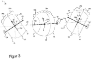
- Figure 3 shows a plan view of three identically configured transport rollers 81, 8m, 8r with differently oriented pivot axes 201, 20m, 20r according to a preferred embodiment of the invention to illustrate how the direction of movement of goods 26 can be influenced.
- the axis of rotation 10m and pivot axis 20m are as already in FIG Figure 1 and 2 shown in a plane, so that a good 4 is transported orthogonally to the pivot axis 20 in the main transport direction 26h.
- the pivot axis 201 of the left transport roller 81 was rotated negatively by 90 °, which is shown in the drawing of FIG Figure 1 and 2 corresponds to turning the axis of rotation 10 out of the plane of the drawing towards the viewer.
- a good 4 is transported to the left in a deflected transport direction 26a, which includes an angle of rotation axis 22 with the main transport direction 26h.
- the pivot axis 20r was positively rotated by 90 °, which is shown in FIG Figure 1 and 2 corresponds to turning the axis of rotation 10 into the plane of the drawing away from the viewer.
- the pivot axis 20 is rotated less than or by + -90 °.
- a support point 27 of a good 4 is always located on the transport roller 8 only on the good contact surface 28g and not on the drive means contact surface 28a. Since there is no greater deflection of the pivot axis 20 than 90 °, there is no mixing of the contact surfaces 28a, 28g.
- a design of the transport roller 8 as a solid ball would allow a complete 360 ° rotation of the pivot axis 20, but the maximum possible angle of the deflected transport direction is already reached after a rotation of + -90 °. In addition, this would also cause the contact surfaces 28a, 28g to mix and thus not allow the use of different materials.
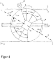
- FIG. 4 shows a cross section of a transport roller 8 of a conveyor system 2 as in FIG Figure 1 and 2 shown with a arranged below the transport plane 6 cover 40 according to a preferred embodiment of the invention.
- the cover 40 comprises a recess 42 for the transport roller 8.
- the recess 42 is circular.
- the circumferential surface 14 of the transport roller 8 is divided into a drive means contact surface 28a, a product contact surface 28g and also includes a protruding surface 42 that does not come into contact with the product 4 or the drive means 12 - even after the rotation of the Pivot axis 20.
- the protruding surface 42 ensures that a perfect spherical surface-like surface 14 of the transport roller 8 protrudes from the cover 40, i.e.
- cover 40 no gap opens between the cover 40 and the transport roller 8, i.e. no catching, squeezing and / or shearing points arise . If a greater rotation of the pivot axis 20 than + -90 ° were possible, no cover 40 could be used.
- the cover 40 protects the conveyor system 2, in particular the bearing 38 with its moving parts, from damage by an item 4 and vice versa and from contamination and operating personnel from injuries.
- the transport roller 8 is derived from a ball with a diameter of 80 mm and the axis of rotation 10 is arranged at an axis of rotation angle 22 of 30 ° to the pivot axis 20.
- the good contact surface 28g extends over an angular extent of precisely the rotation axis angle 22, that is to say 30 °.
- the cover 40 is arranged 2 mm below the transport plane 6, so that the protruding surface 44 has an angular extent of 20 ° or even more - depending on the desired safety margin.
- the drive means contact surface 28a has an angular extent of 35 ° - of which 30 ° are due to the rotation axis angle 22, as well as an additional safety margin of 5 ° to prevent an edge of the transport roller 8 from rubbing on the drive means 12.
- the effective radius 32r is 32.9 mm for the in Figure 4 arrangement shown.
- the shaft 21 is a square with a square cross-section and a side length of 10 mm.
- Figure 5 shows a side view of a plurality of transport rollers 8a, 8b, 8c comprising conveyor system 2 according to a preferred embodiment of the invention.
- the transport rollers 8a, 8b, 8c are arranged along a width of the transport plane 6 on a common shaft 21 with a common and thus identical pivot axis 20, so that the item 4 is simultaneously deflected by several transport rollers 8a, 8b, 8c.
- the good 4 rests on three support points 27a, 27b, 27c on the transport rollers 8a, 8b, 8c and is thus guided even better. This prevents unintentional rotation of the good 4, which can happen in particular if only one transport roller 8 acts on a good 3.
- transport rollers 8 arranged along a width of the transport plane 6 also make it possible to deflect two or more goods 4 transported next to one another on the transport plane 6 at the same time - at least if the arrangement of the transport rollers 8 is just as wide as the two or more goods 4 next to one another.
- the three transport rollers 8a, 8b, 8c are driven together in a rotating manner. This can be carried out in a technically particularly simple manner with a drive means 12 if the transport rollers 8a, 8b, 8c as in FIG Figure 5 shown are mounted together on a shaft 21.
- the shaft 21 is arranged along the common and thus identical pivot axis 20 of the three transport rollers 8a, 8b, 8c.
- the transport rollers 8a, 8b, 8c are similarly set obliquely with the same axis of rotation angle 22i on the shaft 21 and therefore have parallel axes of rotation 10a, 10b, 10c.
- the axes of rotation 10a, 10b, 10c remain even when the Pivot axis 20 always parallel to one another.
- additional transport rollers 8 can be arranged along a length of the transport plane 6 in a conveyor system 2. If the additional transport rollers 8 are exactly like those in Figure 5
- the transport rollers 8a, 8b, 8c shown are arranged on a second, common shaft 21z and thus with an identical pivot axis 22z and additionally have the same identical rotation axis angle 22i as the transport rollers 8a, 8b, 8c, the additional transport rollers 8 steer one or more goods 4 when setting the same pivot axis angle from the same - at least when the second shaft 21z is arranged parallel to the shaft 22 of the transport rollers 8a, 8b, 8c.
- the transport rollers 8 and 8a, 8b, 8c then have parallel pivot axes 22, 22z.
- the transport rollers 8a, 8b, 8c have a common and thus identical pivot axis 22.
- One or more goods 4 are thus deflected in the same way from all transport rollers 8, 8a, 8b, 8c, which enables particularly simple control of the transport rollers 8.
- the direction 26 of the goods can be changed several times along the path covered by the goods 4 by rotating the pivot axes 22. If the multiple transport rollers 8 along a length and width of the transport plane 6, the transport rollers 8 form a ball-roller carpet-like conveyor system 2. To drive an item 4 around an imaginary curve, rotation axis angles 22 and / or pivot axis angles be different. Swivel axes 20 that are not parallel to one another along the transport plane 6 can also bring about this.
- Figure 6 shows, according to a further preferred embodiment of the invention, a conveyor system 2 which comprises a transport chute 46 which is designed in particular for goods 4 such as packages and pieces of luggage and can thus be used as the end point of a sorter of a mail sorting system.
- the transport chute 46 comprises at least one slide section which has an inclined slide surface 6rf with a direction of fall 47 of the goods 4 along the slide surface.
- the slide surface 6rf thus represents the at least partially inclined transport plane 6, with a typical inclination of about 5 °, and comprises at least one several transport rollers 8, which are arranged along the width and length of the transport plane 6 of the transport slide 46 and can be used as a roller carpet-like width distribution device.
- Every six of the transport rollers 8 have a common pivot axis 20, that is to say form a row of transport rollers, and all transport rollers 8 have identical rotation axis angles 22 and thus rotation axes 10 aligned in parallel with a pivot axis angle of 0 °.
- the transport rollers 8 of the transport chute 46 are designed to transport the goods via gravity conveyance.
- the transport rollers 8 are designed as gravity rollers which can be moved by the dead weight of the goods 4 and which include braking rollers that keep the running speed constant.
- An additional braking function can be integrated into the roller conveyor using various techniques, including, for example, a brake motor, a friction brake or a centrifugal clutch.
- Another possibility of braking an item 4 and thereby transporting it along the transport chute 46 in a controlled manner consists in each of the Arranged at a height to arrange transport rollers 8 so that the rows of transport rollers alternately deflect in opposite directions.
- the first row of transport rollers with the pivot axis 20x could initially deflect an item 4 by a steering angle of + 10 ° to the direction of fall 47 and the second, as well as every other row of transport rollers with the pivot axis 20y, have a steering angle of -10 °.
- the third, as well as every further row of transport rollers with the pivot axis 20z, would then deflect again by a steering angle of + 10 °.
- larger goods 4 which are usually also heavier, lie on several rows of rollers and thus have a corresponding sliding friction component in their conveyance, depending on the amount of the steering angle, whereby the conveyance is braked.
- This sliding friction component can be adjusted by the amount of the steering angle, the steering angle being dependent on both the rotation axis angle 22 and the pivot axis angle. Since gravity conveying uses the weight of the goods 4 to drive them, it enables a particularly simple, energy-efficient and low-maintenance construction to drive the transport rollers 8.
- a good 4 is introduced into the transport chute 46 from a sorter with the aid of an inward transfer device 48.
- the material Before being introduced, the material has a direction of movement that does not correspond to the direction of fall 47 with the same linear speed component as the sorter, for example 2.5 m / s.
- Goods 4 therefore accumulate without influencing their trajectory 50 along the slide surface 6rf due to their inertia on the left-hand side of the transport chute 46 in the drawing, as does the goods 4a, since the linear speed component of the sorter is largely retained and only unregulated by friction is braked.
- either the pivot axes 20x, 20y, 20z can be rotated by less than 90 °, or only one or two of the pivot axes 20x, 20y, 20z is rotated.
- the transport rollers 8 are designed to be steered by a control device 52 and for this purpose can be connected to it.
- the trajectory 50 of the goods 4 can thus be influenced in a flexible manner.
- the goods can be blindly steered and distributed with the help of an already existing good format knowledge.
- Another possibility is to use a detector 54 and / or sensor that can be connected to the control device 52 in order to detect the position of the goods 4 on the transport chute 46 and then to control it.
- the control device 52 is designed, based on the position of the goods 4 on the transport chute 46 to control the goods 4 just passing the sliding surface 6rf.
- the use of the transport rollers 8 in transport chutes 46 enables wider transport chutes 46 without partition walls between the end points. This has the advantage of a flexible division of narrow low-volume and wide high-volume terminals. After being dropped, the goods are directed down exactly onto their individual lane.
- two or more transport chutes 46 which are analogous to those in FIG Figure 6 are configured, one behind the other in the direction of fall 47 and / or slightly horizontally offset, so that a transport slide cascade is formed.
- goods are identified, for example with the aid of the detector 54.
- the transport chutes 46 do not directly adjoin one another, a gap is formed through which the goods 4 can be steered with the help of the transport rollers 8 to the next transport chute 46, so that this task no longer has to be performed by a human operator.
- the conveyor system 2 can be used as an ascending conveyor, the transport level 6 being inclined in the ascending conveyor, with a main transport direction 26h against a slope of the transport level 6, the slope having an incline of 12 °, for example.
- the ascending conveyor does not necessarily have to be designed to be steerable with transport rollers 8 for The use of a revolving drive means 12 is also possible for transporting the goods 4.
- a transport chute 46 for example the one shown in FIG. 6, connects to the ascending conveyor.
- sorter module In order to form a sorter module, the ascending conveyor and the transport chute 46 are regularly lined up next to one another. With the transport rollers 8, the goods 4 can optionally be transported to one side or the other or in a straight line.
- sorter modules can be arranged one behind the other and thus form a modular, expandable sorter with low throughput.
- scaling of the conveyor system 2 is possible without any problems, so that an overall division of the conveyor system 2 is possible without any problems. Smaller rotation axis angles 22 lead to less wear.
Description
Die Erfindung bezieht sich auf das technische Gebiet der Fördersysteme für Güter, insbesondere auf das gerichtete Fördern erlaubende Fördersysteme.The invention relates to the technical field of conveyor systems for goods, in particular to conveyor systems that allow directional conveying.
Ein gerichtetes Fördern von Gütern in einstellbare Transportrichtungen auf einer Förderstrecke hat besondere Bedeutung in Sortieranlagen, insbesondere Post- und Gepäcksortieranlagen, und Fertigungsanlagen. Eine in die Förderstrecke integrierte Lösung zum Einstellen der Transportrichtungen kann teure Komponenten, beispielsweise einen Eckumsetzer, überflüssig machen. Insbesondere bei fragilen Gütern ist es vorteilhaft, wenn das Fördern schonend abläuft, also ohne Kollisionen mit einem Rand der Förderstrecke oder anderen Komponenten, wodurch die Güter beschädigt werden können. Auf Transportrutschen sammeln sich Güter nach ihrem Abwurf aufgrund ihrer Trägheit häufig auf einer Ansammlungsseite an, wodurch eine vollständige Ausnutzung der Transportrutschenbreite als Speicherplatz erschwert ist.A directed conveying of goods in adjustable transport directions on a conveyor line is of particular importance in sorting systems, in particular mail and baggage sorting systems, and manufacturing systems. A solution integrated into the conveyor line for setting the transport directions can make expensive components, such as a corner transfer device, superfluous. In the case of fragile goods in particular, it is advantageous if the conveying is carried out gently, i.e. without collisions with an edge of the conveying path or other components, which could damage the goods. On transport chutes, goods often collect on one side of the accumulation after being dropped due to their inertia, which makes it difficult to fully utilize the width of the transport chute as storage space.
Stand der Technik zum gerichteten Fördern ist die Verwendung von Schwenkrollen, welche auf einer vertikalen Achse gelagert sind. Um diese Achse werden die Schwenkrollen einzeln oder als Zeile über Lenker in ihrer Winkeleinstellung verändert, wie dies zum Beispiel durch
Eine andere Lösung verwendet orthogonal freidrehende Rollen. Wenn in eine spezifische Richtung aktiv gefördert werden soll, werden zusätzliche Rollen an ein Gut hochgefahren. Eine weitere Lösung verwendet eine zylindrische, in einem Gliedergurt schräg angeordnete Rolle. Ein Quertransport wird ausgelöst, indem eine Reibfläche von unten an den Gliedergurt gebracht wird, wodurch die zylindrische Rolle eine Zwangsbewegung ausführt. Bei Transportrutschen werden an einer Rutschseite angebrachte Abweiserbleche genutzt, die den Gütern bei einem Abprallen einen Impuls weg von der Ansammlungsseite geben. Alternativ wird die Transportrutsche leicht quer geneigt, um die Schwerkraft auszunutzen. Beide Lösungen führen jedoch nur zu einer leicht verbesserten, jedoch lange nicht gleichmäßigen Verteilung der Güter entlang der Rutschbreite und können darüber hinaus die Güter beschädigen. Daher ist eine verbesserte Lösung weiterhin erforderlich.Another solution uses orthogonally freely rotating rollers. If active conveyance is to be carried out in a specific direction, additional roles are run up to a good. Another solution uses a cylindrical roller, which is arranged at an angle in a link belt. A transverse transport is triggered by bringing a friction surface onto the link belt from below, as a result of which the cylindrical roller executes a forced movement. In the case of transport chutes, deflector plates attached to one side of the slide are used to hold the goods on a ricochet, give an impulse away from the accumulation side. Alternatively, the transport chute is inclined slightly transversely in order to take advantage of gravity. Both solutions, however, only lead to a slightly improved, but for a long time not uniform, distribution of the goods along the width of the slide and can also damage the goods. Therefore, an improved solution is still needed.
Die oben dargestellten Lösungen umfassen eine Vielzahl an bewegten Teilen und Lagern, sind daher in ihrer technischen Realisierung relativ aufwendig und somit auch fehleranfällig und/ oder können die Güter beschädigen.The solutions presented above include a large number of moving parts and bearings, are therefore relatively complex in their technical implementation and thus also prone to errors and / or can damage the goods.
Der vorliegenden Erfindung liegt daher die Aufgabe zugrunde, eine technisch einfach realisierbare, robuste und güterschonende Lösung zum gerichteten Fördern von Gütern mit vielseitigem Einsatzbereich zu ermöglichen. Diese Aufgabe wird durch die in den unabhängigen Ansprüchen beschriebenen Lösungen gelöst.The present invention is therefore based on the object of providing a technically simple, robust and goods-friendly solution for the directed conveying of goods with a wide range of uses. This object is achieved by the solutions described in the independent claims.
Die erfindungsgemäße Lösung sieht ein Fördersystem vor, welches geeignet ist zum Transport von Gütern auf einer Transportebene. Das Fördersystem umfasst mindestens eine für den Transport der Güter vorgesehene Transportrolle, welche zumindest in einem für einen Kontakt mit den Gütern vorgesehenen Bereich eine umlaufende kugeloberflächenausschnittartige Oberfläche aufweist. Die mindestens eine Transportrolle ist um ihre Drehachse rotierbar und das Fördersystem weist mindestens eine Schwenkachse auf, um welche die Drehachse durch Rotation verstellbar ist.The solution according to the invention provides a conveyor system which is suitable for transporting goods on a transport level. The conveyor system comprises at least one transport roller which is provided for the transport of the goods and which has a circumferential surface like a segment of a spherical surface at least in an area provided for contact with the goods. The at least one transport roller can be rotated about its axis of rotation and the conveyor system has at least one pivot axis about which the axis of rotation can be adjusted by rotation.
Gemäß einer bevorzugten Ausführungsform kann die mindestens eine Schwenkachse im Wesentlichen parallel zur Transportebene angeordnet sein. Dies ermöglicht eine Befestigung der Schwenkachse parallel unterhalb der Transportebene und erlaubt eine Rotation der Schwenkachse um ein Gut abzulenken ohne Beeinträchtigung seines Transportweges auf der Förderstrecke.According to a preferred embodiment, the at least one pivot axis can be arranged essentially parallel to the transport plane. This enables the Swivel axis parallel below the transport plane and allows rotation of the swivel axis to deflect an item without impairing its transport path on the conveyor line.
Um auf besonders einfache Art und Weise eine gerichtetes Fördern eines Gutes zu ermöglichen, können die Drehachse und die mindestens eine Schwenkachse einen Drehachsenwinkel einschließen. Bei paralleler Anordnung der Schwenkachse, orthogonal zu einer unabgelenkten Transportrichtung des Gutes, kann so eine beidseitige Ablenkung, um den Drehachsenwinkel oder geringer, erzielt werden.In order to enable a directed conveying of a good in a particularly simple manner, the axis of rotation and the at least one pivot axis can enclose an angle of the axis of rotation. With a parallel arrangement of the pivot axis, orthogonal to an undeflected transport direction of the goods, a deflection on both sides, around the axis of rotation angle or less, can be achieved.
Um einen aktiven und/ oder passiven, gelenkten Transport von Gütern auf der Transportebene mit der mindestens einen Transportrolle auf unterschiedliche Weise zu ermöglichen, kann die mindestens eine Transportrolle antreibbar sein. Die mindestens eine Transportrolle kann insbesondere um ihre Drehachse mit einem Antrieb in der Transportrolle und/ oder einem unterhalb der Transportrolle angeordneten Antriebsmittel und/ oder Schwerkraftförderung antreibbar sein. Insbesondere die Schwerkraftförderung ermöglicht einen besonders energiearmen Antrieb bei gleichzeitiger Überwindung eines Höhenunterschieds, beispielsweise auf einer Transportrutsche als zumindest teilweise geneigte Transportebene.In order to enable active and / or passive, guided transport of goods on the transport level with the at least one transport roller in different ways, the at least one transport roller can be drivable. The at least one transport roller can in particular be drivable about its axis of rotation with a drive in the transport roller and / or a drive means and / or gravity conveyor arranged below the transport roller. In particular, gravity conveying enables a particularly low-energy drive while at the same time overcoming a height difference, for example on a transport chute as an at least partially inclined transport plane.
Um eine besonders einfache Positionierung der Transportrolle im Fördersystem mit einem gängigen Bauteil zu erzielen, insbesondere mit einer definierten Lage auf einer Welle, kann das Fördersystem mindestens einen Schrägsteller umfassen, mit welchem die Drehachse der mindestens einen Transportrolle schräg einstellbar ist.In order to achieve a particularly simple positioning of the transport roller in the conveyor system with a common component, in particular with a defined position on a shaft, the conveyor system can include at least one tilting device with which the axis of rotation of the at least one transport roller can be set at an angle.
Um einen wartungsarmen Betrieb des Fördersystems, mit einer reibungsarmen Rotation der mindestens einen Transportrolle um ihre Drehachse zu erzielen, kann die mindestens eine Transportrolle mindestens ein Lager, insbesondere ein Wälzlager, umfassen.In order to achieve low-maintenance operation of the conveyor system with low-friction rotation of the at least one transport roller about its axis of rotation, the at least one transport roller can comprise at least one bearing, in particular a roller bearing.
Um einen möglichsten guten Schutz der Bauteile des Fördersystems unterhalb der Transportebene zu erzielen und um zu verhindern, dass sich die Güter im Fördersystem verfangen und dabei beschädigt werden, kann eine Abdeckung unterhalb der Transportebene angeordnet sein, wobei die Abdeckung eine Aussparung für jede Transportrolle umfasst.In order to achieve the best possible protection of the components of the conveyor system below the transport level and to prevent the goods from getting caught in the conveyor system and being damaged in the process, a cover can be arranged below the transport level, the cover comprising a recess for each transport roller.
Um über einen möglichst großen Bereich eine möglichst effektive Ablenkung von einem Gut oder mehreren Gütern und/ oder eine gleichzeitige Ablenkung von mehr als einem Gut zu erzielen, kann das Fördersystem mehrere Transportrollen umfassen, die entlang einer Breite und/ oder einer Länge der Transportebene angeordnet sind. So können die mehreren Transportrollen ein Gut oder mehrere Güter über die Breite und/ oder Länge der Transportebene geführt transportiert werden. Die Transportrollen können ein rollenteppichartiges Fördersystem ausbilden.In order to achieve as effective a deflection as possible from one item or several items and / or a simultaneous deflection of more than one item over the largest possible area, the conveyor system can comprise several transport rollers which are arranged along a width and / or a length of the transport plane . In this way, the multiple transport rollers can transport a good or multiple goods over the width and / or length of the transport plane. The transport rollers can form a roller carpet-like conveyor system.
Gemäß einer bevorzugten Ausführungsform kann die Transportrolle kugelartig oder kugelzonenartig ausgestaltet sein. Bei einer vollständig kugelartigen Ausgestaltung der Transportrolle ist die gesamte Oberfläche der Transportrolle umlaufend kugeloberflächenartig und somit für einen Kontakt mit den Gütern vorgesehen. Dadurch kann die Transportrolle vollständig um ihre Schwenkachse rotiert werden. Bei einer kugelzonenartigen Ausgestaltung der Transportrolle kann die Oberfläche der Transportrolle in einem über dem mit Kontakt mit den Gütern vorgesehenen Bereich umlaufend kugeloberflächenartig sein, wodurch Transportebene und eine weitere Tangentialfläche stets einen gleichen Abstand aufweisen.According to a preferred embodiment, the transport roller can be configured in the manner of a sphere or a sphere zone. In the case of a completely spherical configuration of the transport roller, the entire surface of the transport roller is circumferentially in the manner of a spherical surface and is therefore intended for contact with the goods. As a result, the transport roller can be rotated completely around its pivot axis. In the case of a configuration of the transport roller in the manner of a spherical zone, the surface of the transport roller can circumferentially resemble a spherical surface in an area provided over the area provided for contact with the goods be, whereby the transport plane and another tangential surface always have the same distance.
Um eine besonders einfache Rotation der mindestens einen Transportrolle um ihre Schwenkachse zu ermöglichen, können die eine oder die mehreren Transportrollen auf mindestens einer Welle gelagert sein. Bei Lagerung auf nur einer Welle kann besonders einfach eine gleichzeitige Rotation der auf dieser Welle gelagerten Transportrollen erreicht werden, bei Lagerung auf mehr als einer Welle kann besonders einfach eine individuelle Rotation der einzelnen Wellen und somit von je einer oder mehrerer auf besagter Welle gelagerter Transportrollen erreicht werden.In order to enable a particularly simple rotation of the at least one transport roller about its pivot axis, the one or more transport rollers can be mounted on at least one shaft. When mounted on only one shaft, simultaneous rotation of the transport rollers mounted on this shaft can be achieved particularly easily; when mounted on more than one shaft, individual rotation of the individual shafts and thus of one or more transport rollers mounted on said shaft can be achieved particularly easily will.
Damit sich Welle und die mindestens eine Transportrolle auch ohne oder bei unterbrochener Kraftübertragung nicht voneinander lösen können und damit die Welle und die mindestens eine Transportrolle besonders gut ineinandergreifen, kann die mindestens eine Welle formschlüssig und/ oder kraftschlüssig mit der mindestens einen Transportrolle verbindbar sein. Damit sind Welle und Transportrolle gegen Verdrehen gesichert, was eine effiziente Weiterleitung einer Rotationsbewegung über die Welle an die mindestens eine Transportrolle erlaubt.So that the shaft and the at least one transport roller cannot separate from each other without or with interrupted power transmission and so that the shaft and the at least one transport roller interlock particularly well, the at least one shaft can be positively and / or non-positively connectable to the at least one transport roller. The shaft and transport roller are thus secured against twisting, which allows a rotational movement to be efficiently passed on via the shaft to the at least one transport roller.
Hinsichtlich eines Verfahrens wird die vorstehend genannte Aufgabe gelöst durch ein Verfahren zum Transport von Gütern mit einem Fördersystem auf einer Transportebene, wobei das Fördersystem mindestens eine für den Transport der Güter vorgesehene Transportrolle umfasst, welche zumindest in einem für einen Kontakt mit den Gütern vorgesehenen Bereich eine umlaufende kugeloberflächenausschnittartige Oberfläche aufweist. Die Transportrolle ist um ihre Drehachse rotierbar und das Fördersystem weist mindestens eine Schwenkachse auf, um welche die Drehachse durch Rotation verstellbar ist. Das Verfahren umfasst den Verfahrensschritt eines rotierendes Antreibens der mindestens einen Transportrolle, insbesondere mit einem Antrieb in der Transportrolle und/ oder einem unterhalb der Transportrolle angeordneten Antriebsmittel und/ oder Schwerkraftförderung.With regard to a method, the above-mentioned object is achieved by a method for transporting goods with a conveyor system on a transport level, wherein the conveyor system comprises at least one transport roller provided for transporting the goods, which has a roller at least in an area provided for contact with the goods having circumferential spherical surface section-like surface. The transport roller can be rotated about its axis of rotation and the conveyor system has at least one pivot axis about which the axis of rotation can be adjusted by rotation. The procedure comprises the method step of rotating the at least one transport roller, in particular with a drive in the transport roller and / or a drive means and / or gravity feed arranged below the transport roller.
Um auf besonders einfache Weise eine Richtungsänderung eines auf der Transportebene transportierten Gutes zu erzielen, kann eine Schrägstellung der Drehachse der mindestens einen Transportrolle um ihren Drehachsenwinkel und/ oder ein Verstellen der Drehachse durch Rotation um ihre Schwenkachse erfolgen.In order to achieve a change in direction of goods transported on the transport plane in a particularly simple manner, the axis of rotation of the at least one transport roller can be inclined by its axis of rotation angle and / or the axis of rotation can be adjusted by rotating around its pivot axis.
Um mehr als eine Transportrolle mit geringem Betriebsaufwand zu betreiben, kann ein gemeinsames rotierendes Antreiben von mehr als einer Transportrolle erfolgen. Das gemeinsame rotierende Antreiben kann besonders einfach erfolgen, wenn mehr als eine Transportrolle auf einer Welle gelagert ist.In order to operate more than one transport roller with little operational expenditure, a common rotating drive of more than one transport roller can take place. The common rotating drive can take place particularly easily if more than one transport roller is mounted on a shaft.
Um mit mehreren Transportrollen gleichzeitig ein oder mehrere Güter konzertiert in eine gleiche Transportrichtung oder in verschiedene Transportrichtungen zu transportieren, können zwei oder mehr der Transportrollen parallele und/ der nicht parallele Drehachsen, parallele und/ oder identische Schwenkachsen und gleiche und/ oder verschiedene Schwenkachsenwinkel aufweisen.In order to simultaneously transport one or more goods in concert with several transport rollers in the same transport direction or in different transport directions, two or more of the transport rollers can have parallel and / or non-parallel axes of rotation, parallel and / or identical swivel axes and the same and / or different swivel axis angles.
Bevorzugte Ausführungsbeispiele der Erfindung werden nachfolgend anhand der Figuren beispielsweise näher erläutert. Dabei zeigen:
- Figur 1
- schematisch eine seitliche Ansicht eines Fördersystems;
Figur 2- ein Fördersystem wie in
Figur 1 dargestellt mit technischen Details einer Transportrolle; - Figur 3
- eine Aufsicht auf drei Transportrollen mit unterschiedlich ausgerichteten Schwenkachsen;
- Figur 4
- einen Querschnitt einer Transportrolle mit einer Abdeckung;
- Figur 5
- eine seitliche Ansicht eines mehrere Transportrollen umfassenden Fördersystems; und
Figur 6- eine Transportrutsche.
- Figure 1
- schematically a side view of a conveyor system;
- Figure 2
- a conveyor system as in
Figure 1 shown with technical details of a transport roller; - Figure 3
- a plan view of three transport rollers with differently aligned pivot axes;
- Figure 4
- a cross section of a transport roller with a cover;
- Figure 5
- a side view of a multiple transport rollers comprising conveyor system; and
- Figure 6
- a transport chute.
Die Transportrolle 8 weist eine von einer Kugel hergeleitete Form auf, so dass die Transportrolle 8 zumindest in einem für einen Kontakt mit dem Gut 4 vorgesehenen Bereich eine umlaufende kugeloberflächenartige Oberfläche 14 aufweist. Wie die Form der Transportrolle 8 von einer Kugel abgeleitet ist, ist mit einem teilweise gestrichelten Umkreis 16 angedeutet. Die in
Das Fördersystem 2 weist eine Schwenkachse 20 auf, um welche die die gesamte Transportrolle 8 samt ihrer Drehachse 10 durch Rotation verstellbar ist. Die Schwenkachse 20 ist im Wesentlichen parallel zur und unterhalb der Transportebene 6 angeordnet. Die Transportrolle 8 ist auf einer Welle 21 gelagert. Drehachse 10 und Schwenkachse 20 schließen einen Drehachsenwinkel 22 ein. Da die Form der Transportrolle 8 von einer Kugel hergeleitet ist, ändert sich der Abstand zwischen den beiden oben eingeführten Tangentialflächen nicht. Durch den punktförmigen Auflagepunkt 27 des Gutes 4 auf der Transportrolle 8 bewirkt ein rotierendes Antreiben der Drehachse 10 mit einem positiven Drehachsen-Drehsinn 24 wie in
Wenn nur eine maximale Auslenkung der Drehachse 10 um +-90° erlaubt ist, kommt das Gut 4 nur mit einer Hälfte der Oberfläche 14, einer Gut-Kontaktfläche 28g, in Kontakt; das Antriebsmittel 12 hingegen kommt nur mit der anderen Hälfte der 14, einer Antriebsmittel-Kontaktfläche 28a, in Kontakt.If only a maximum deflection of the axis of
Die Gut-Kontaktfläche 28g und die Antriebsmittel-Kontaktfläche 28a werden von einer Schnittfläche 30, welche den Mittelpunkt der durch den Umkreis 16 angedeuteten Kugel umfasst und orthogonal zur Drehachse 10 ausgerichtet ist, getrennt. Eine Trennung von Gut-Kontaktfläche 28g und Antriebsmittel-Kontaktfläche 28a ermöglicht einen Einsatz unterschiedlicher Materialien, die jeweils für eine optimale Kraftübertragung zwischen Gut 4 bzw. Antriebsmittel 12 und Transportrolle 8 optimiert sind.The
Durch die Schrägstellung der Drehachse 10 um den Drehachsenwinkel 22 hat die Transportrolle 8 bei Rotation um ihre Drehachse 10 einen Wirkradius 32w, welcher kleiner als ein Kugelradius 32r ist. Daraus folgt für eine Transportrolle 8 mit eigenem Antrieb, dass die Geschwindigkeitskomponente in Gut-Laufrichtung 26 auch bei Ablenkung gleich bleibt. Bei steigender Verstellung wächst der Wirkradius 32w bis auf das Maß des Kugelradius 32r. Das heißt, die Querkomponente des Geschwindigkeitsvektors wird inhärent erhöht. Bei einem Antrieb über Antriebsmittel 12 ist immer eine Drehzahlanpassung des Antriebsmittels 12 bei größerem Drehachsenwinkel 22 erforderlich, um das Gut 4 mit gleichbleibender Geschwindigkeit zu transportieren.As a result of the inclination of the axis of
Um eine reibungsarmes rotierendes Antreiben der Transportrolle 8 und somit einen energieeffizienten Transport des Gutes 4 zu ermöglichen, umfasst die Transportrolle 8 ein als Wälzlager 36 ausgestaltetes Lager. Eine Ausgestaltung des Lagers als Gleitlager wäre ebenfalls möglich. Das Wälzlager 36, das beispielsweise als Kugellager ausgestaltet sein kann, und Schrägsteller 34 sind Teil eines Lagers 38 der Transportrolle 8.In order to enable low-friction rotating driving of the
Schrägsteller 34, Welle 21, und insbesondere Schwenkachse 20 und Transportrolle 8 sind formschlüssig und optional zur zusätzlichen Absicherung noch kraftschlüssig miteinander verbindbar ausgestaltet, so dass eine besonders effiziente Weiterleitung von Rotationsbewegungen erfolgt, da sich Schwenkachse 20, Schrägsteller 34 und insbesondere Transportrolle 8 und Welle 21 so nicht gegeneinander verdrehen können. Formschlüssig verzahnte Verbindungen sind außerdem besonders stabil und wartungsarm. Sie können besonders einfach als Spritzgussteile realisiert werden. Die Verbindungen könnten jedoch auch rein kraftschlüssig ausgestaltet werden.Tilting device 34,
Die Schwenkachse 201 der linken Transportrolle 81 wurde negativ um 90° rotiert, was in der zeichnerischen Darstellung von
Um innerhalb des vom Drehachsenwinkel 22 vorgegebenen Rahmens andere Gut-Laufrichtungen 26 zu erzielen, wird die Schwenkachse 20 weniger als oder um +-90° rotiert. Bei allen drei Transportrollen 81, 8m, 8r befindet sich ein Auflagepunkt 27 eines Gutes 4 auf der Transportrolle 8 stets nur auf der Gut-Kontaktfläche 28g und nicht auf der Antriebsmittel-Kontaktfläche 28a. Da keine größere Auslenkung der Schwenkachse 20 als 90° erfolgt, kommt es zu keiner Vermischung der Kontaktflächen 28a, 28g. Eine Ausgestaltung der Transportrolle 8 als Vollkugel würde eine vollständige 360°-Rotation der Schwenkachse 20 erlauben, allerdings ist bereits nach einer Rotation um +-90° der maximal mögliche Winkel der abgelenkten Transportrichtung erreicht. Darüber hinaus würde dies auch eine Vermischung der Kontaktflächen 28a, 28g bewirken und somit keinen Einsatz unterschiedlicher Materialien erlauben.In order to achieve other
Im Folgenden sollen geometrische Verhältnisse und Größenverhältnisse des Fördersystems 2 exemplarisch mit einem Zahlenbeispiel veranschaulicht werden. Die Transportrolle 8 ist abgeleitet von einer Kugel mit 80 mm Durchmesser und die Drehachse 10 ist in einem Drehachsenwinkel 22 von 30° zur Schwenkachse 20 angeordnet. Die Gut-Kontaktfläche 28g erstreckt sich über eine Winkelausdehnung von eben dem Drehachsenwinkel 22, also 30°. Die Abdeckung 40 ist 2 mm unterhalb der Transportebene 6 angeordnet, so dass die Überstand-Oberfläche 44 eine Winkelausdehnung von 20° oder auch mehr - je nach gewünschter Sicherheitsmarge - aufweist. Die Antriebsmittel-Kontaktfläche 28a weist eine Winkelausdehnung von 35° auf - davon sind 30° durch den Drehachsenwinkel 22 bedingt, sowie zusätzlich ein Sicherheitsaufschlag von 5° um ein Reiben einer Kante der Transportrolle 8auf dem Antriebsmittel 12 zu verhindern. 32,9 mm beträgt der Wirkradius 32r bei der in
Es erfolgt ein gemeinsames rotierendes Antreiben der drei Transportrollen 8a, 8b, 8c. Dies kann technisch besonders einfach mit einem Antriebsmittel 12 durchgeführt werden, wenn die Transportrollen 8a, 8b, 8c wie in
Zusätzlich zu einer Anordnung der Transportrollen 8a, 8b, 8c entlang der Breite der Transportebene 6, können in einem Fördersystem 2 noch zusätzliche Transportrollen 8 entlang einer Länge der Transportebene 6 angeordnet sein. Wenn die zusätzlichen Transportrollen 8 genau wie die in
Bei einer Anordnung der Transportrollen 8 entlang der Länge der Transportebene 6 kann die Gut-Laufrichtung 26 mehrfach entlang des vom Gut 4 zurückgelegten Weges durch Rotation der Schwenkachsen 22 verändert werden. Wenn die mehreren Transportrollen 8 entlang einer Länge und Breite der Transportebene 6, bilden die Transportrollen 8 ein kugelrollenteppichartiges Fördersystem 2. Um ein Gut 4 um eine gedachte Kurve zu fahren, können Drehachsenwinkel 22 und/ oder Schwenkachsenwinkel unterschiedliche sein. Auch nicht zueinander parallele Schwenkachsen 20 entlang der Transportebene 6 können dies bewirken.When the
Die Transportrollen 8 der Transportrutsche 46 sind ausgestaltet, die Güter über Schwerkraftförderung zu transportieren. Hierzu sind die Transportrollen 8 als von dem Eigengewicht der Güter 4 bewegbare Schwerkraftrollen ausgestaltet, die Bremsrollen, die die Ablaufgeschwindigkeit konstant halten, umfassen. Eine zusätzliche Bremsfunktion kann durch verschiedene Techniken in die Rollenbahn integriert werden, die beispielsweise einen Bremsmotor, eine Friktionsbremse oder eine Zentrifugalkupplung umfassen. Eine weitere Möglichkeit, ein Gut 4 zu bremsen und dadurch kontrolliert die Transportrutsche 46 entlang zu transportieren, besteht darin, die jeweils auf einer Höhe angeordneten Transportrollen 8 so anzuordnen so anzuordnen, dass die Transportrollenzeilen abwechseln gegensinnig ablenken. So könnte beispielsweise die erste Transportrollenzeile mit der Schwenkachse 20x ein Gut 4 zunächst um einen Lenkwinkel von +10° zur Fallrichtung 47 ablenken und die zweite, sowie jede weitere übernächste Transportrollenzeile mit der Schwenkachse 20y einen Lenkwinkel von -10° aufweisen. Die dritte, sowie jede weitere übernächste Transportrollenzeile mit der Schwenkachse 20z würde dann wieder um einen Lenkwinkel von +10° ablenken. Insbesondere größere Güter 4, die meist auch schwerer sind, liegen auf mehreren Rollenzeilen auf und haben damit je nach Betrag des Lenkwinkels einen entsprechenden Gleitreibungsanteil bei ihrer Förderung, wodurch die Förderung gebremst wird. Dieser Gleitreibungsanteil ist durch den Betrag des Lenkwinkels einstellbar, wobei der Lenkwinkel abhängig von sowohl Drehachsenwinkel 22, als auch Schwenkachsenwinkel ist. Da die Schwerkraftförderung die Gewichtskraft der Güter 4 zum Antrieb ausnutzt, ermöglicht sie eine besonders einfache, energieeffiziente und wartungsarme Konstruktion, um die Transportrollen 8 anzutreiben.The
Ein Gut 4 wird mit Hilfe einer Einschleusvorrichtung 48 ausgehend von einem Sorter in die Transportrutsche 46 eingeschleust. Vor dem Einschleusen weist das Gut eine nicht mit der Fallrichtung 47 übereinstimmende Bewegungsrichtung auf mit einer gleichen linearen Geschwindigkeitskomponente wie der Sorter, beispielsweise 2,5m/s. Daher sammeln sich Güter 4 ohne Beeinflussung ihrer Trajektorie 50 entlang der Rutschfläche 6rf aufgrund ihrer Trägheit auf der in der zeichnerischen Darstellung linken Seite der Transportrutsche 46 an, so wie das Gut 4a, da die lineare Geschwindigkeitskomponente des Sorters weitgehend erhalten bleibt und nur durch Reibung ungeregelt abgebremst wird. Es baut sich so eine unsymmetrische Befüllung der Transportrutsche 46 auf Wenn sich Drehachsen 10 und Schwenkachsen 20 in einer Ebene befinden, die orthogonal zur Fallrichtung 47 ist, der Schwenkachsenwinkel also 0° ist, ändern die Transportrollen 8 die Trajektorie 50 eines Gutes nicht. Das Gut 4a hat die Trajektorie 50a zurückgelegt. In
Um ein Gut 4 weniger stark als das Gut 4b abzulenken, können entweder die Schwenkachsen 20x, 20y, 20z um weniger als 90° rotiert werden, oder aber nur eine oder zwei der Schwenkachsen 20x, 20y, 20z wird rotiert.In order to deflect a good 4 less strongly than the good 4b, either the pivot axes 20x, 20y, 20z can be rotated by less than 90 °, or only one or two of the pivot axes 20x, 20y, 20z is rotated.
Da eine Rotation der Schwenkachsen 20x, 20y, 20z der Transportrollen 8 einfach und rasch erfolgt, sind die Güter flexibel lenkbar. Die Transportrollen 8 sind ausgestaltet, von einer Steuervorrichtung 52 gelenkt zu werden und hierzu mit dieser verbindbar. So ist die Trajektorie 50 der Güter 4 flexibel beeinflussbar. Einerseits können die Güter mit Hilfe von einem bereits existierenden Gut-Format-Vorwissen blind gelenkt und verteilt werden. Eine andere Möglichkeit ist die Verwendung eines mit der Steuervorrichtung 52 verbindbaren Detektors 54 und/ oder Sensors, um die Position der Güter 4 auf der Transportrutsche 46 zu detektieren und anschließend zu steuern. Hierzu ist die Steuervorrichtung 52 ausgestaltet, ausgehend von der Position der Güter 4 auf der Transportrutsche 46 die gerade die Rutschfläche 6rf passierenden Güter 4 zu steuern.Since the pivot axes 20x, 20y, 20z of the
Gemäß einer weiteren bevorzugten Ausführungsform der Erfindung ermöglicht eine Verwendung der Transportrollen 8 in Transportrutschen 46, breitere Transportrutschen 46 ohne Trennwände zwischen den Endstellen. Dies hat den Vorteil einer flexiblen Einteilung von schmalen Low-Volume- und breiten High-Volume-Endstellen. Die Güter werden also nach dem Abwurf exakt auf ihre individuelle Spur nach unten gelenkt.According to a further preferred embodiment of the invention, the use of the
Gemäß einer weiteren bevorzugten Ausführungsform der Erfindung werden zwei oder mehr Transportrutschen 46, die analog zu den in
Gemäß einer weiteren bevorzugten Ausführungsform der Erfindung ist das Fördersystem 2 als Steigförderer verwendbar, wobei bei dem Steigförderer die Transportebene 6 geneigt ist, mit einer Haupt-Transportrichtung 26h gegen ein Gefälle der Transportebene 6, wobei das Gefälle beispielswiese eine Steigung von 12° aufweist. Der Steigförderer muss nicht notwendigerweise lenkbar mit Transportrollen 8 ausgestaltet sein, zum Transport der Güter 4 ist auch eine Verwendung eines umlaufenden Antriebsmittels 12 möglich. An den Steigförderer schließt eine Transportrutsche 46, beispielsweise die in Figur 6 dargestellte, an.According to a further preferred embodiment of the invention, the
Um ein Sorter-Modul auszubilden, werden Steigförderer und Transportrutsche 46 regelmäßig aneinander gereiht. Mit den Transportrollen 8 können die Güter 4 wahlweise zur einen oder anderen Seite oder geradeaus transportiert werden. Mehrere Sorter-Module können hintereinander angeordnet werden und so einen modular erweiterbaren Sorter geringer Durchsatzleistung ausbilden.In order to form a sorter module, the ascending conveyor and the
Gemäß einer weiteren bevorzugten Ausführungsform der Erfindung ist eine Skalierung des Fördersystems 2 problemlos möglich, so dass eine Gesamtteilung des Fördersystems 2 problemlos möglich ist. Kleinere Drehachsenwinkel 22 führen zu einem geringeren Verschleiß.According to a further preferred embodiment of the invention, scaling of the
- 22
- FördersystemConveyor system
- 44th
- GutGood
- 66th
- TransportebeneTransport level
- 88th
- TransportrolleTransport roller
- 1010
- DrehachseAxis of rotation
- 1212th
- AntriebsmittelDrive means
- 1414th
-
kugeloberflächenartige Oberfläche der Transportrolle 8spherical surface-like surface of the
transport roller 8 - 1616
- Umkreis einer KugelPerimeter of a sphere
- 1818th
- SchnittebeneCutting plane
- 2020th
- SchwenkachseSwivel axis
- 2121
- Wellewave
- 2222nd
- DrehachsenwinkelRotation axis angle
- 2424
- Drehachsen-DrehsinnDirection of rotation of the axis of rotation
- 2626th
- Gut-LaufrichtungGood running direction
- 26h26h
- Haupt-TransportrichtungMain direction of transport
- 26a26a
- abgelenkte Transportrichtungdeflected transport direction
- 2727
- AuflagepunktSupport point
- 28a28a
- Antriebsmittel-KontaktflächeDrive means contact surface
- 28g28g
- Gut-KontaktflächeGood contact area
- 3030th
-
Schnittfläche zwischen Antriebsmittel-Kontaktfläche 28a und Gut-Kontaktfläche 28gCut surface between drive means
contact surface 28a andgood contact surface 28g - 32w32w
- WirkradiusEffective radius
- 32r32r
- KugelradiusSphere radius
- 3434
- SchrägstellerTilters
- 3636
- Wälzlagerroller bearing
- 3838
- Lagercamp
- 4040
- Abdeckungcover
- 4242
- AussparungRecess
- 4444
- Überstand-OberflächeOverhang surface
- 4646
- TransportrutscheTransport chute
- 4747
- FallrichtungDirection of fall
- 4848
- EinschleusvorrichtungInfeed device
- 5050
- Trajektorie eines Gutes 4 entlang der Rutschfläche 6rfTrajectory of a good 4 along the sliding surface 6rf
- 5252
- SteuervorrichtungControl device
- 5454
- Detektordetector
Claims (15)
- Conveying system (2) suited to transporting goods on a transport level (6), whereina) the conveying system (2) comprises at least one transport roller (8) provided for the transportation of the goods (4), which has a peripheral surface (14) in the manner of a spherical surface section at least in a region provided for contact with goods;b) the at least one transport roller (8) can be rotated about an axis of rotation (10); andcharacterised in that
the conveying system (2) has at least one swivel axis (20), about which the axis of rotation (10) can be adjusted by means of rotation. - Conveying system (2) according to claim 1,
characterised in that
the at least one swivel axis (20) is arranged substantially parallel to the transport level (6). - Conveying system (2) according to one of claims 1 to 2,
characterised in that
the axis of rotation (10) and the at least one swivel axis (20) include an axis of rotation angle (22). - Conveying system (2) according to one of claims 1 to 3,
characterised in that
the at least one transport roller (8) can be driven, in particular about its axis of rotation (10) with a drive in the transport roller (8) and/or a drive means (12) and/or gravity feed arranged below the transport roller (8). - Conveying system (2) according to one of claims 1 to 4,
characterised in that
the conveying system (2) comprises at least one oblique adjustment unit (34) with which the axis of rotation (10) of the at least one transport roller (8) can be adjusted obliquely. - Conveying system (2) according to one of claims 1 to 5,
characterised in that
the at least one transport roller (8) comprises at least one bearing, in particular a roller bearing (36). - Conveying system (2) according to one of claims 1 to 6,
characterised in that
a cover (40) is arranged below the transport level (6), wherein the cover (40) comprises a recess (42) for each transport roller (8). - Conveying system (2) according to one of claims 1 to 7,
characterised in that
the conveying system (2) comprises a number of transport rollers (8), which are arranged along a width and/or a length of the transport level (6). - Conveying system (2) according to one of claims 1 to 8,
characterised in that
the transport roller (8) is designed in the manner of a sphere or spherical zone. - Conveying system (2) according to one of claims 1 to 9,
characterised in that
the one or more transport rollers (8) are mounted on at least one shaft (21). - Conveying system (2) according to claim 10,
characterised in that
the at least one shaft (21) can be connected to the at least one transport roller (8) in a form-fit and/or force-fit manner. - Method for transporting goods with a conveying system (2) on a transport level (6), whereina) the conveying system (2) comprises at least one transport roller (8) provided for transportation of the goods (4), which has a peripheral surface (14) in the manner of a spherical surface section at least in a region provided for contact with the goods;b) the transport roller (8) can be rotated about its axis of rotation (10); andc) the conveying system (2) has at least one swivel axis (20), about which the axis of rotation (10) can be adjusted by means of rotation;comprising the method step
of a rotating driving of the at least one transport roller (8), in particular with a drive in the transport roller (8) and/or a drive means (12) and/or gravity feed arranged below the transport roller (8). - Method according to claim 12,
characterised by
an oblique positioning of the axis of rotation (10) of the at least one transport roller (8) about its axis of rotation angle (22) and/or an adjustment of the axis of rotation (10) by rotation about its swivel axis (20). - Method according to one of claims 12 to 13,
characterised by
a shared rotating driving of more than one transport roller (8) . - Method according to one of claims 12 to 14,
characterised in that
two or more of the transport rollers (8) have parallel and/or non-parallel axes of rotation (10), parallel and/or identical swivel axes (20) and identical and/or different swivel axis angles.
Priority Applications (2)
| Application Number | Priority Date | Filing Date | Title |
|---|---|---|---|
| EP15198158.6A EP3178759B1 (en) | 2015-12-07 | 2015-12-07 | Transport roller conveying system |
| PCT/EP2016/077791 WO2017097552A1 (en) | 2015-12-07 | 2016-11-16 | Transport roller conveyor system |
Applications Claiming Priority (1)
| Application Number | Priority Date | Filing Date | Title |
|---|---|---|---|
| EP15198158.6A EP3178759B1 (en) | 2015-12-07 | 2015-12-07 | Transport roller conveying system |
Publications (2)
| Publication Number | Publication Date |
|---|---|
| EP3178759A1 EP3178759A1 (en) | 2017-06-14 |
| EP3178759B1 true EP3178759B1 (en) | 2021-09-01 |
Family
ID=54783494
Family Applications (1)
| Application Number | Title | Priority Date | Filing Date |
|---|---|---|---|
| EP15198158.6A Active EP3178759B1 (en) | 2015-12-07 | 2015-12-07 | Transport roller conveying system |
Country Status (2)
| Country | Link |
|---|---|
| EP (1) | EP3178759B1 (en) |
| WO (1) | WO2017097552A1 (en) |
Cited By (1)
| Publication number | Priority date | Publication date | Assignee | Title |
|---|---|---|---|---|
| DE102021111667A1 (en) | 2021-05-05 | 2022-11-10 | Lippert Gmbh & Co. Kg | Parcel diverter for conveying and sorting piece goods |
Families Citing this family (1)
| Publication number | Priority date | Publication date | Assignee | Title |
|---|---|---|---|---|
| FR3047478B1 (en) * | 2016-02-04 | 2018-03-09 | Fives Intralogistics S.A. | DEVICE AND METHOD FOR DEVIATION OF ARTICLES TO BE SORTED, AND SORT INSTALLATION COMPRISING SUCH A DEVICE |
Family Cites Families (2)
| Publication number | Priority date | Publication date | Assignee | Title |
|---|---|---|---|---|
| WO2014066838A1 (en) * | 2012-10-25 | 2014-05-01 | Intelligrated Headquarters, Llc | Transmission having variable output orientation |
| JP6517825B2 (en) * | 2014-02-12 | 2019-05-22 | アヴァンコン・エスアー | Transport assembly for a transport system |
-
2015
- 2015-12-07 EP EP15198158.6A patent/EP3178759B1/en active Active
-
2016
- 2016-11-16 WO PCT/EP2016/077791 patent/WO2017097552A1/en active Application Filing
Cited By (1)
| Publication number | Priority date | Publication date | Assignee | Title |
|---|---|---|---|---|
| DE102021111667A1 (en) | 2021-05-05 | 2022-11-10 | Lippert Gmbh & Co. Kg | Parcel diverter for conveying and sorting piece goods |
Also Published As
| Publication number | Publication date |
|---|---|
| WO2017097552A1 (en) | 2017-06-15 |
| EP3178759A1 (en) | 2017-06-14 |
Similar Documents
| Publication | Publication Date | Title |
|---|---|---|
| EP2874923B1 (en) | Omnidirectional conveying system module, modular omnidirectional conveying system, and omnidirectional conveying system | |
| EP3287396B1 (en) | Conveyor system with segments | |
| EP2560898A1 (en) | Matrix conveyor for use as a sorter or palletizing device | |
| EP2088099B1 (en) | Supply device for vertical transport of bulk goods | |
| EP3357839A1 (en) | Method and conveyor system for manipulating an original flow of goods | |
| EP1731450A1 (en) | Device for separating, transporting and grouping articles | |
| EP2910499A1 (en) | Transport system and method for transporting suspending items | |
| EP3162742A1 (en) | Sorting mechanism with distributed control | |
| EP3178759B1 (en) | Transport roller conveying system | |
| EP2399848B1 (en) | Device for dividing a supply stream of upright containers | |
| WO2021037610A1 (en) | Apparatus and method for conveying and sorting articles | |
| WO2010022820A1 (en) | Device for separating product groups | |
| EP0718219A2 (en) | Singulating device | |
| EP3357841A1 (en) | Modular conveyor unit | |
| EP3196154A1 (en) | Conveying system for goods comprising an alignment device | |
| EP3319889B1 (en) | Goods alignment device | |
| EP3305691A1 (en) | Conveying system with guide device | |
| WO2022129342A1 (en) | Container supply device and method for operating the container supply device | |
| EP3587026B1 (en) | Compact separator | |
| EP4001187A1 (en) | Method for transverse positioning of an article to be transported | |
| CH669773A5 (en) | ||
| CH707448A1 (en) | Conveyor system. | |
| DE20319973U1 (en) | Roller conveyor for crates has vertical roller which can be raised above conveyor surface and turns crates through right angle, e.g. for further processing | |
| WO2017198354A1 (en) | Conveying portion for conveying material to be sorted in different directions | |
| EP3733489B1 (en) | Treatment system for treating workpieces |
Legal Events
| Date | Code | Title | Description |
|---|---|---|---|
| PUAI | Public reference made under article 153(3) epc to a published international application that has entered the european phase |
Free format text: ORIGINAL CODE: 0009012 |
|
| STAA | Information on the status of an ep patent application or granted ep patent |
Free format text: STATUS: THE APPLICATION HAS BEEN PUBLISHED |
|
| AK | Designated contracting states |
Kind code of ref document: A1 Designated state(s): AL AT BE BG CH CY CZ DE DK EE ES FI FR GB GR HR HU IE IS IT LI LT LU LV MC MK MT NL NO PL PT RO RS SE SI SK SM TR |
|
| AX | Request for extension of the european patent |
Extension state: BA ME |
|
| RAP1 | Party data changed (applicant data changed or rights of an application transferred) |
Owner name: SIEMENS AKTIENGESELLSCHAFT |
|
| STAA | Information on the status of an ep patent application or granted ep patent |
Free format text: STATUS: REQUEST FOR EXAMINATION WAS MADE |
|
| 17P | Request for examination filed |
Effective date: 20171211 |
|
| RBV | Designated contracting states (corrected) |
Designated state(s): AL AT BE BG CH CY CZ DE DK EE ES FI FR GB GR HR HU IE IS IT LI LT LU LV MC MK MT NL NO PL PT RO RS SE SI SK SM TR |
|
| GRAP | Despatch of communication of intention to grant a patent |
Free format text: ORIGINAL CODE: EPIDOSNIGR1 |
|
| STAA | Information on the status of an ep patent application or granted ep patent |
Free format text: STATUS: GRANT OF PATENT IS INTENDED |
|
| INTG | Intention to grant announced |
Effective date: 20210521 |
|
| GRAS | Grant fee paid |
Free format text: ORIGINAL CODE: EPIDOSNIGR3 |
|
| GRAA | (expected) grant |
Free format text: ORIGINAL CODE: 0009210 |
|
| STAA | Information on the status of an ep patent application or granted ep patent |
Free format text: STATUS: THE PATENT HAS BEEN GRANTED |
|
| AK | Designated contracting states |
Kind code of ref document: B1 Designated state(s): AL AT BE BG CH CY CZ DE DK EE ES FI FR GB GR HR HU IE IS IT LI LT LU LV MC MK MT NL NO PL PT RO RS SE SI SK SM TR |
|
| REG | Reference to a national code |
Ref country code: GB Ref legal event code: FG4D Free format text: NOT ENGLISH |
|
| REG | Reference to a national code |
Ref country code: CH Ref legal event code: EP Ref country code: AT Ref legal event code: REF Ref document number: 1426036 Country of ref document: AT Kind code of ref document: T Effective date: 20210915 |
|
| REG | Reference to a national code |
Ref country code: DE Ref legal event code: R096 Ref document number: 502015015132 Country of ref document: DE |
|
| REG | Reference to a national code |
Ref country code: IE Ref legal event code: FG4D Free format text: LANGUAGE OF EP DOCUMENT: GERMAN |
|
| REG | Reference to a national code |
Ref country code: NL Ref legal event code: FP |
|
| REG | Reference to a national code |
Ref country code: LT Ref legal event code: MG9D |
|
| PG25 | Lapsed in a contracting state [announced via postgrant information from national office to epo] |
Ref country code: LT Free format text: LAPSE BECAUSE OF FAILURE TO SUBMIT A TRANSLATION OF THE DESCRIPTION OR TO PAY THE FEE WITHIN THE PRESCRIBED TIME-LIMIT Effective date: 20210901 Ref country code: BG Free format text: LAPSE BECAUSE OF FAILURE TO SUBMIT A TRANSLATION OF THE DESCRIPTION OR TO PAY THE FEE WITHIN THE PRESCRIBED TIME-LIMIT Effective date: 20211201 Ref country code: NO Free format text: LAPSE BECAUSE OF FAILURE TO SUBMIT A TRANSLATION OF THE DESCRIPTION OR TO PAY THE FEE WITHIN THE PRESCRIBED TIME-LIMIT Effective date: 20211201 Ref country code: ES Free format text: LAPSE BECAUSE OF FAILURE TO SUBMIT A TRANSLATION OF THE DESCRIPTION OR TO PAY THE FEE WITHIN THE PRESCRIBED TIME-LIMIT Effective date: 20210901 Ref country code: FI Free format text: LAPSE BECAUSE OF FAILURE TO SUBMIT A TRANSLATION OF THE DESCRIPTION OR TO PAY THE FEE WITHIN THE PRESCRIBED TIME-LIMIT Effective date: 20210901 Ref country code: HR Free format text: LAPSE BECAUSE OF FAILURE TO SUBMIT A TRANSLATION OF THE DESCRIPTION OR TO PAY THE FEE WITHIN THE PRESCRIBED TIME-LIMIT Effective date: 20210901 Ref country code: RS Free format text: LAPSE BECAUSE OF FAILURE TO SUBMIT A TRANSLATION OF THE DESCRIPTION OR TO PAY THE FEE WITHIN THE PRESCRIBED TIME-LIMIT Effective date: 20210901 Ref country code: SE Free format text: LAPSE BECAUSE OF FAILURE TO SUBMIT A TRANSLATION OF THE DESCRIPTION OR TO PAY THE FEE WITHIN THE PRESCRIBED TIME-LIMIT Effective date: 20210901 |
|
| PG25 | Lapsed in a contracting state [announced via postgrant information from national office to epo] |
Ref country code: PL Free format text: LAPSE BECAUSE OF FAILURE TO SUBMIT A TRANSLATION OF THE DESCRIPTION OR TO PAY THE FEE WITHIN THE PRESCRIBED TIME-LIMIT Effective date: 20210901 Ref country code: LV Free format text: LAPSE BECAUSE OF FAILURE TO SUBMIT A TRANSLATION OF THE DESCRIPTION OR TO PAY THE FEE WITHIN THE PRESCRIBED TIME-LIMIT Effective date: 20210901 Ref country code: GR Free format text: LAPSE BECAUSE OF FAILURE TO SUBMIT A TRANSLATION OF THE DESCRIPTION OR TO PAY THE FEE WITHIN THE PRESCRIBED TIME-LIMIT Effective date: 20211202 |
|
| PG25 | Lapsed in a contracting state [announced via postgrant information from national office to epo] |
Ref country code: IS Free format text: LAPSE BECAUSE OF FAILURE TO SUBMIT A TRANSLATION OF THE DESCRIPTION OR TO PAY THE FEE WITHIN THE PRESCRIBED TIME-LIMIT Effective date: 20220101 Ref country code: SM Free format text: LAPSE BECAUSE OF FAILURE TO SUBMIT A TRANSLATION OF THE DESCRIPTION OR TO PAY THE FEE WITHIN THE PRESCRIBED TIME-LIMIT Effective date: 20210901 Ref country code: SK Free format text: LAPSE BECAUSE OF FAILURE TO SUBMIT A TRANSLATION OF THE DESCRIPTION OR TO PAY THE FEE WITHIN THE PRESCRIBED TIME-LIMIT Effective date: 20210901 Ref country code: RO Free format text: LAPSE BECAUSE OF FAILURE TO SUBMIT A TRANSLATION OF THE DESCRIPTION OR TO PAY THE FEE WITHIN THE PRESCRIBED TIME-LIMIT Effective date: 20210901 Ref country code: PT Free format text: LAPSE BECAUSE OF FAILURE TO SUBMIT A TRANSLATION OF THE DESCRIPTION OR TO PAY THE FEE WITHIN THE PRESCRIBED TIME-LIMIT Effective date: 20220103 Ref country code: EE Free format text: LAPSE BECAUSE OF FAILURE TO SUBMIT A TRANSLATION OF THE DESCRIPTION OR TO PAY THE FEE WITHIN THE PRESCRIBED TIME-LIMIT Effective date: 20210901 Ref country code: CZ Free format text: LAPSE BECAUSE OF FAILURE TO SUBMIT A TRANSLATION OF THE DESCRIPTION OR TO PAY THE FEE WITHIN THE PRESCRIBED TIME-LIMIT Effective date: 20210901 Ref country code: AL Free format text: LAPSE BECAUSE OF FAILURE TO SUBMIT A TRANSLATION OF THE DESCRIPTION OR TO PAY THE FEE WITHIN THE PRESCRIBED TIME-LIMIT Effective date: 20210901 |
|
| REG | Reference to a national code |
Ref country code: DE Ref legal event code: R097 Ref document number: 502015015132 Country of ref document: DE |
|
| PLBE | No opposition filed within time limit |
Free format text: ORIGINAL CODE: 0009261 |
|
| STAA | Information on the status of an ep patent application or granted ep patent |
Free format text: STATUS: NO OPPOSITION FILED WITHIN TIME LIMIT |
|
| PG25 | Lapsed in a contracting state [announced via postgrant information from national office to epo] |
Ref country code: MC Free format text: LAPSE BECAUSE OF FAILURE TO SUBMIT A TRANSLATION OF THE DESCRIPTION OR TO PAY THE FEE WITHIN THE PRESCRIBED TIME-LIMIT Effective date: 20210901 Ref country code: DK Free format text: LAPSE BECAUSE OF FAILURE TO SUBMIT A TRANSLATION OF THE DESCRIPTION OR TO PAY THE FEE WITHIN THE PRESCRIBED TIME-LIMIT Effective date: 20210901 |
|
| REG | Reference to a national code |
Ref country code: CH Ref legal event code: PL |
|
| 26N | No opposition filed |
Effective date: 20220602 |
|
| REG | Reference to a national code |
Ref country code: DE Ref legal event code: R081 Ref document number: 502015015132 Country of ref document: DE Owner name: KOERBER SUPPLY CHAIN LOGISTICS GMBH, DE Free format text: FORMER OWNER: SIEMENS AKTIENGESELLSCHAFT, 80333 MUENCHEN, DE |
|
| GBPC | Gb: european patent ceased through non-payment of renewal fee |
Effective date: 20211207 |
|
| PG25 | Lapsed in a contracting state [announced via postgrant information from national office to epo] |
Ref country code: SI Free format text: LAPSE BECAUSE OF FAILURE TO SUBMIT A TRANSLATION OF THE DESCRIPTION OR TO PAY THE FEE WITHIN THE PRESCRIBED TIME-LIMIT Effective date: 20210901 |
|
| REG | Reference to a national code |
Ref country code: NL Ref legal event code: PD Owner name: KOERBER SUPPLY CHAIN LOGISTICS GMBH; DE Free format text: DETAILS ASSIGNMENT: CHANGE OF OWNER(S), ASSIGNMENT; FORMER OWNER NAME: SIEMENS AKTIENGESELLSCHAFT Effective date: 20220824 |
|
| REG | Reference to a national code |
Ref country code: BE Ref legal event code: MM Effective date: 20211231 |
|
| PG25 | Lapsed in a contracting state [announced via postgrant information from national office to epo] |
Ref country code: LU Free format text: LAPSE BECAUSE OF NON-PAYMENT OF DUE FEES Effective date: 20211207 Ref country code: IE Free format text: LAPSE BECAUSE OF NON-PAYMENT OF DUE FEES Effective date: 20211207 Ref country code: GB Free format text: LAPSE BECAUSE OF NON-PAYMENT OF DUE FEES Effective date: 20211207 |
|
| REG | Reference to a national code |
Ref country code: DE Ref legal event code: R082 Ref document number: 502015015132 Country of ref document: DE Representative=s name: MUELLER SCHUPFNER & PARTNER PATENT- UND RECHTS, DE |
|
| PG25 | Lapsed in a contracting state [announced via postgrant information from national office to epo] |
Ref country code: BE Free format text: LAPSE BECAUSE OF NON-PAYMENT OF DUE FEES Effective date: 20211231 |
|
| PG25 | Lapsed in a contracting state [announced via postgrant information from national office to epo] |
Ref country code: LI Free format text: LAPSE BECAUSE OF NON-PAYMENT OF DUE FEES Effective date: 20211231 Ref country code: CH Free format text: LAPSE BECAUSE OF NON-PAYMENT OF DUE FEES Effective date: 20211231 |
|
| REG | Reference to a national code |
Ref country code: AT Ref legal event code: MM01 Ref document number: 1426036 Country of ref document: AT Kind code of ref document: T Effective date: 20211207 |
|
| PG25 | Lapsed in a contracting state [announced via postgrant information from national office to epo] |
Ref country code: AT Free format text: LAPSE BECAUSE OF NON-PAYMENT OF DUE FEES Effective date: 20211207 |
|
| PG25 | Lapsed in a contracting state [announced via postgrant information from national office to epo] |
Ref country code: HU Free format text: LAPSE BECAUSE OF FAILURE TO SUBMIT A TRANSLATION OF THE DESCRIPTION OR TO PAY THE FEE WITHIN THE PRESCRIBED TIME-LIMIT; INVALID AB INITIO Effective date: 20151207 |
|
| PGFP | Annual fee paid to national office [announced via postgrant information from national office to epo] |
Ref country code: IT Payment date: 20221227 Year of fee payment: 8 |
|
| P01 | Opt-out of the competence of the unified patent court (upc) registered |
Effective date: 20230523 |
|
| PG25 | Lapsed in a contracting state [announced via postgrant information from national office to epo] |
Ref country code: CY Free format text: LAPSE BECAUSE OF FAILURE TO SUBMIT A TRANSLATION OF THE DESCRIPTION OR TO PAY THE FEE WITHIN THE PRESCRIBED TIME-LIMIT Effective date: 20210901 |
|
| PGFP | Annual fee paid to national office [announced via postgrant information from national office to epo] |
Ref country code: NL Payment date: 20231219 Year of fee payment: 9 Ref country code: FR Payment date: 20231219 Year of fee payment: 9 Ref country code: DE Payment date: 20230912 Year of fee payment: 9 |