EP3287396B1 - Conveyor system with segments - Google Patents
Conveyor system with segments Download PDFInfo
- Publication number
- EP3287396B1 EP3287396B1 EP16185726.3A EP16185726A EP3287396B1 EP 3287396 B1 EP3287396 B1 EP 3287396B1 EP 16185726 A EP16185726 A EP 16185726A EP 3287396 B1 EP3287396 B1 EP 3287396B1
- Authority
- EP
- European Patent Office
- Prior art keywords
- conveying means
- piece goods
- conveying
- segment
- conveyor
- Prior art date
- Legal status (The legal status is an assumption and is not a legal conclusion. Google has not performed a legal analysis and makes no representation as to the accuracy of the status listed.)
- Active
Links
- 238000000034 method Methods 0.000 claims description 12
- 230000004044 response Effects 0.000 claims description 5
- 230000032258 transport Effects 0.000 description 19
- 238000000926 separation method Methods 0.000 description 15
- 238000012546 transfer Methods 0.000 description 8
- 230000000284 resting effect Effects 0.000 description 7
- 238000004364 calculation method Methods 0.000 description 6
- 238000013461 design Methods 0.000 description 4
- 238000012937 correction Methods 0.000 description 3
- 230000008901 benefit Effects 0.000 description 1
- 230000008859 change Effects 0.000 description 1
- 238000010276 construction Methods 0.000 description 1
- 230000003111 delayed effect Effects 0.000 description 1
- 238000001514 detection method Methods 0.000 description 1
- 230000000694 effects Effects 0.000 description 1
- 230000005484 gravity Effects 0.000 description 1
- 238000002955 isolation Methods 0.000 description 1
- 238000012423 maintenance Methods 0.000 description 1
- 230000003287 optical effect Effects 0.000 description 1
- 230000008569 process Effects 0.000 description 1
- 238000012545 processing Methods 0.000 description 1
Images


Classifications
-
- B—PERFORMING OPERATIONS; TRANSPORTING
- B65—CONVEYING; PACKING; STORING; HANDLING THIN OR FILAMENTARY MATERIAL
- B65G—TRANSPORT OR STORAGE DEVICES, e.g. CONVEYORS FOR LOADING OR TIPPING, SHOP CONVEYOR SYSTEMS OR PNEUMATIC TUBE CONVEYORS
- B65G37/00—Combinations of mechanical conveyors of the same kind, or of different kinds, of interest apart from their application in particular machines or use in particular manufacturing processes
-
- B—PERFORMING OPERATIONS; TRANSPORTING
- B65—CONVEYING; PACKING; STORING; HANDLING THIN OR FILAMENTARY MATERIAL
- B65G—TRANSPORT OR STORAGE DEVICES, e.g. CONVEYORS FOR LOADING OR TIPPING, SHOP CONVEYOR SYSTEMS OR PNEUMATIC TUBE CONVEYORS
- B65G43/00—Control devices, e.g. for safety, warning or fault-correcting
- B65G43/10—Sequence control of conveyors operating in combination
-
- G—PHYSICS
- G05—CONTROLLING; REGULATING
- G05B—CONTROL OR REGULATING SYSTEMS IN GENERAL; FUNCTIONAL ELEMENTS OF SUCH SYSTEMS; MONITORING OR TESTING ARRANGEMENTS FOR SUCH SYSTEMS OR ELEMENTS
- G05B13/00—Adaptive control systems, i.e. systems automatically adjusting themselves to have a performance which is optimum according to some preassigned criterion
- G05B13/02—Adaptive control systems, i.e. systems automatically adjusting themselves to have a performance which is optimum according to some preassigned criterion electric
- G05B13/0265—Adaptive control systems, i.e. systems automatically adjusting themselves to have a performance which is optimum according to some preassigned criterion electric the criterion being a learning criterion
-
- B—PERFORMING OPERATIONS; TRANSPORTING
- B07—SEPARATING SOLIDS FROM SOLIDS; SORTING
- B07C—POSTAL SORTING; SORTING INDIVIDUAL ARTICLES, OR BULK MATERIAL FIT TO BE SORTED PIECE-MEAL, e.g. BY PICKING
- B07C1/00—Measures preceding sorting according to destination
- B07C1/02—Forming articles into a stream; Arranging articles in a stream, e.g. spacing, orientating
- B07C1/04—Forming a stream from a bulk; Controlling the stream, e.g. spacing the articles
-
- B—PERFORMING OPERATIONS; TRANSPORTING
- B07—SEPARATING SOLIDS FROM SOLIDS; SORTING
- B07C—POSTAL SORTING; SORTING INDIVIDUAL ARTICLES, OR BULK MATERIAL FIT TO BE SORTED PIECE-MEAL, e.g. BY PICKING
- B07C1/00—Measures preceding sorting according to destination
- B07C1/02—Forming articles into a stream; Arranging articles in a stream, e.g. spacing, orientating
- B07C1/06—Orientating; Aligning ; Aligning to one edge
-
- B—PERFORMING OPERATIONS; TRANSPORTING
- B65—CONVEYING; PACKING; STORING; HANDLING THIN OR FILAMENTARY MATERIAL
- B65G—TRANSPORT OR STORAGE DEVICES, e.g. CONVEYORS FOR LOADING OR TIPPING, SHOP CONVEYOR SYSTEMS OR PNEUMATIC TUBE CONVEYORS
- B65G15/00—Conveyors having endless load-conveying surfaces, i.e. belts and like continuous members, to which tractive effort is transmitted by means other than endless driving elements of similar configuration
- B65G15/22—Conveyors having endless load-conveying surfaces, i.e. belts and like continuous members, to which tractive effort is transmitted by means other than endless driving elements of similar configuration comprising a series of co-operating units
-
- B—PERFORMING OPERATIONS; TRANSPORTING
- B65—CONVEYING; PACKING; STORING; HANDLING THIN OR FILAMENTARY MATERIAL
- B65G—TRANSPORT OR STORAGE DEVICES, e.g. CONVEYORS FOR LOADING OR TIPPING, SHOP CONVEYOR SYSTEMS OR PNEUMATIC TUBE CONVEYORS
- B65G43/00—Control devices, e.g. for safety, warning or fault-correcting
- B65G43/08—Control devices operated by article or material being fed, conveyed or discharged
-
- B—PERFORMING OPERATIONS; TRANSPORTING
- B65—CONVEYING; PACKING; STORING; HANDLING THIN OR FILAMENTARY MATERIAL
- B65G—TRANSPORT OR STORAGE DEVICES, e.g. CONVEYORS FOR LOADING OR TIPPING, SHOP CONVEYOR SYSTEMS OR PNEUMATIC TUBE CONVEYORS
- B65G47/00—Article or material-handling devices associated with conveyors; Methods employing such devices
- B65G47/22—Devices influencing the relative position or the attitude of articles during transit by conveyors
- B65G47/24—Devices influencing the relative position or the attitude of articles during transit by conveyors orientating the articles
- B65G47/244—Devices influencing the relative position or the attitude of articles during transit by conveyors orientating the articles by turning them about an axis substantially perpendicular to the conveying plane
- B65G47/2445—Devices influencing the relative position or the attitude of articles during transit by conveyors orientating the articles by turning them about an axis substantially perpendicular to the conveying plane by means of at least two co-operating endless conveying elements
-
- B—PERFORMING OPERATIONS; TRANSPORTING
- B65—CONVEYING; PACKING; STORING; HANDLING THIN OR FILAMENTARY MATERIAL
- B65G—TRANSPORT OR STORAGE DEVICES, e.g. CONVEYORS FOR LOADING OR TIPPING, SHOP CONVEYOR SYSTEMS OR PNEUMATIC TUBE CONVEYORS
- B65G47/00—Article or material-handling devices associated with conveyors; Methods employing such devices
- B65G47/22—Devices influencing the relative position or the attitude of articles during transit by conveyors
- B65G47/26—Devices influencing the relative position or the attitude of articles during transit by conveyors arranging the articles, e.g. varying spacing between individual articles
- B65G47/30—Devices influencing the relative position or the attitude of articles during transit by conveyors arranging the articles, e.g. varying spacing between individual articles during transit by a series of conveyors
- B65G47/31—Devices influencing the relative position or the attitude of articles during transit by conveyors arranging the articles, e.g. varying spacing between individual articles during transit by a series of conveyors by varying the relative speeds of the conveyors forming the series
-
- G—PHYSICS
- G05—CONTROLLING; REGULATING
- G05B—CONTROL OR REGULATING SYSTEMS IN GENERAL; FUNCTIONAL ELEMENTS OF SUCH SYSTEMS; MONITORING OR TESTING ARRANGEMENTS FOR SUCH SYSTEMS OR ELEMENTS
- G05B19/00—Programme-control systems
- G05B19/02—Programme-control systems electric
- G05B19/418—Total factory control, i.e. centrally controlling a plurality of machines, e.g. direct or distributed numerical control [DNC], flexible manufacturing systems [FMS], integrated manufacturing systems [IMS], computer integrated manufacturing [CIM]
- G05B19/4189—Total factory control, i.e. centrally controlling a plurality of machines, e.g. direct or distributed numerical control [DNC], flexible manufacturing systems [FMS], integrated manufacturing systems [IMS], computer integrated manufacturing [CIM] characterised by the transport system
-
- B—PERFORMING OPERATIONS; TRANSPORTING
- B65—CONVEYING; PACKING; STORING; HANDLING THIN OR FILAMENTARY MATERIAL
- B65G—TRANSPORT OR STORAGE DEVICES, e.g. CONVEYORS FOR LOADING OR TIPPING, SHOP CONVEYOR SYSTEMS OR PNEUMATIC TUBE CONVEYORS
- B65G2201/00—Indexing codes relating to handling devices, e.g. conveyors, characterised by the type of product or load being conveyed or handled
- B65G2201/02—Articles
- B65G2201/0285—Postal items, e.g. letters, parcels
-
- B—PERFORMING OPERATIONS; TRANSPORTING
- B65—CONVEYING; PACKING; STORING; HANDLING THIN OR FILAMENTARY MATERIAL
- B65G—TRANSPORT OR STORAGE DEVICES, e.g. CONVEYORS FOR LOADING OR TIPPING, SHOP CONVEYOR SYSTEMS OR PNEUMATIC TUBE CONVEYORS
- B65G2203/00—Indexing code relating to control or detection of the articles or the load carriers during conveying
- B65G2203/02—Control or detection
- B65G2203/0208—Control or detection relating to the transported articles
- B65G2203/0225—Orientation of the article
-
- B—PERFORMING OPERATIONS; TRANSPORTING
- B65—CONVEYING; PACKING; STORING; HANDLING THIN OR FILAMENTARY MATERIAL
- B65G—TRANSPORT OR STORAGE DEVICES, e.g. CONVEYORS FOR LOADING OR TIPPING, SHOP CONVEYOR SYSTEMS OR PNEUMATIC TUBE CONVEYORS
- B65G2203/00—Indexing code relating to control or detection of the articles or the load carriers during conveying
- B65G2203/02—Control or detection
- B65G2203/0208—Control or detection relating to the transported articles
- B65G2203/0233—Position of the article
-
- B—PERFORMING OPERATIONS; TRANSPORTING
- B65—CONVEYING; PACKING; STORING; HANDLING THIN OR FILAMENTARY MATERIAL
- B65G—TRANSPORT OR STORAGE DEVICES, e.g. CONVEYORS FOR LOADING OR TIPPING, SHOP CONVEYOR SYSTEMS OR PNEUMATIC TUBE CONVEYORS
- B65G2203/00—Indexing code relating to control or detection of the articles or the load carriers during conveying
- B65G2203/04—Detection means
- B65G2203/042—Sensors
- B65G2203/044—Optical
-
- Y—GENERAL TAGGING OF NEW TECHNOLOGICAL DEVELOPMENTS; GENERAL TAGGING OF CROSS-SECTIONAL TECHNOLOGIES SPANNING OVER SEVERAL SECTIONS OF THE IPC; TECHNICAL SUBJECTS COVERED BY FORMER USPC CROSS-REFERENCE ART COLLECTIONS [XRACs] AND DIGESTS
- Y02—TECHNOLOGIES OR APPLICATIONS FOR MITIGATION OR ADAPTATION AGAINST CLIMATE CHANGE
- Y02P—CLIMATE CHANGE MITIGATION TECHNOLOGIES IN THE PRODUCTION OR PROCESSING OF GOODS
- Y02P90/00—Enabling technologies with a potential contribution to greenhouse gas [GHG] emissions mitigation
- Y02P90/02—Total factory control, e.g. smart factories, flexible manufacturing systems [FMS] or integrated manufacturing systems [IMS]
Definitions
- the present invention relates to the technical field of a conveyor system for piece goods.
- Piece goods are transported on a conveyor system along a conveyor route, with manipulation of the piece goods transported along a main transport direction, for example separation and/or rotation, taking place without the use of further devices such as baffles or the like, in that the piece goods are transported via more than one conveyor .
- Singulators are used to separate piece goods in the postal and logistical sectors, which can also partially align the piece goods.
- WO2004/039706 describes a singulator with conveyor belts arranged one behind the other and parallel to one another as conveying means, which transport piece goods along a main conveying direction.
- the conveying means arranged transversely to the main conveying direction and parallel to one another form segments and by controlling the conveying means of a segment differently, the piece goods are separated and/or rotated.
- WO 2006/002156 A1 discloses a conveyor system for transporting piece goods according to the preamble of claim 1 and a method for transporting piece goods according to the preamble of claim 6.
- the present invention is based on the object of transporting piece goods, especially smaller pieces of goods, on a conveyor system and thereby manipulating them efficiently during their transport. This object is achieved by a conveyor system for transporting piece goods according to claim 1 and by a method for transporting piece goods according to claim 6.
- a conveyor system for transporting piece goods, in particular mail items, along a main conveying direction comprising a control unit and a conveying path.
- the conveyor line includes segments that are arranged one behind the other along the main conveying direction.
- the segments comprise conveying means arranged essentially parallel to one another, for example conveyor belts, which are designed to transport the piece goods along the main conveying direction.
- the funding can be driven individually and controlled individually by the control unit.
- the conveying means of neighboring segments are arranged offset from one another transversely to the main conveying direction.
- a segment includes one or more conveyors that are designed to transport the piece goods along the main conveying direction.
- a funding from a previous segment leads to two or more funding from a subsequent segment.
- a segment includes two or more conveyors
- two piece goods transferred in parallel at the same level in a previous segment can be transferred to different conveyors in the following segment. This means that these piece goods can be transported at different speeds by the different conveying means and can therefore be separated. But even if only one item is transferred, but it rests on two different conveyors on the following segment, the alignment can be changed by different speeds of control.
- the segments are arranged offset from one another transversely to the main conveying direction by arranging the conveying means of adjacent segments offset from one another.
- a funding means of a preceding segment flows into two or more funding means of a subsequent segment.
- one or more segments can include similar conveying means.
- the same type of funding can also be controlled in the same way; construction and maintenance require the same expertise for all funding means. This reduces the complexity of the conveyor system.
- the conveyor system can comprise at least one sensor, which is designed to detect the position and/or orientation of the piece goods and the control unit can be adapted to control the conveying means in response to the detected position and/or orientation of the piece goods.
- the conveying means can be controlled particularly efficiently, individually adapted to the respective position and/or orientation of the piece goods on the conveyor system, which can therefore manipulate the piece goods particularly efficiently.
- an initial standard orientation of the piece goods is not necessary.
- control unit can be adapted to rotate and/or separate a piece of goods by controlling the conveying speed of the conveying means, in particular those conveying means on which the piece of goods lies and/or the directly adjacent conveying means.
- a calculation of the rotation and/or separation to be achieved can be carried out with a computing capacity that is adapted to the complexity of the control unit, since all funding can be included in the calculation, but does not have to be.
- a segment comprises one or more conveyors that are designed to transport the piece goods along the main conveying direction.
- the segments arranged one behind the other can be designed very flexibly with regard to the width and arrangement of their conveying means.
- the subsequent segment is arranged offset from the preceding segment by the conveying means of the subsequent one Segments are arranged offset from one another to the funding of the previous segment.
- an offset can be achieved in a particularly simple manner even with funding of different widths.
- a funding means of the preceding segment flows into two or more funding means of the following segment.
- one or more piece goods of the preceding segment initially resting on one conveyor of the preceding segment can be transferred to two or more conveyors of the subsequent segment solely by moving in the main conveying direction and can be further transported individually by individually controlling these conveyors and thus separated and/or rotated . If the conveying means of the preceding and subsequent segments are arranged in a line, the one or more piece goods would also have to be moved transversely to the main conveying direction, which would require more complex conveying means and also a more complicated control.
- the conveying means of adjacent segments can be arranged in such a way that a piece of goods is transferred from one conveying means of the preceding segment to two conveying means of the following segment.
- this arrangement enables a particularly simple separation of two piece goods arranged in parallel on the conveyor of the previous segment after transfer.
- detection can be carried out of the position and/or orientation of the piece goods on the conveyor system and control of the conveying means in response to the detected position and/or orientation of the piece goods.
- rotating and/or separating the piece goods can be done by controlling the conveying speed of the conveying means, in particular those conveying means on which the piece goods rest and/or the directly adjacent conveying means.
- the less funding used for checking the less complex and clearer the calculation and implementation of the procedure.
- the transfer from a previous segment to a subsequent segment involves two or more conveying means. If the piece goods are so small that they rest centrally on only one conveyor of the preceding segment, this ensures that they are transferred to one or more conveyors of the following segment.
- the piece goods are no longer centered on the conveyor of the following segment and can now be manipulated; when transferred to two or more conveyors of the subsequent segment, the piece of goods that are now resting on more than one conveyor can pass through Individually driving these two or more subsidies can be manipulated.
- Figure 1 shows a conveyor system 2 corresponding to the state of the art, which transports piece goods 4 along a main conveying direction 6 on a conveyor line 8 resting on conveyors 12.
- the conveying means 12 are arranged parallel to the main conveying direction 6 in segments 10 arranged one behind the other along the main conveying direction 6, aligned and along a line.
- Such a conveyor system 2 is optimized for transporting and manipulating piece goods 4 of a size that corresponds to the support surface of a conveyor 12.
- a typical area of application for such a conveyor system 2 is singulators in the postal and logistical areas.
- the piece goods 4, here postal items, are transferred from one segment 10 to the following segment 10 for transport.
- Large general cargo 4 lie on one or more conveyors 12 at the same time and can therefore be separated and/or rotated during their transport when the conveyors 12 are individually controlled by a control unit 14 (not shown here), for example by the conveyors 12 on which the piece goods 4 in question rest at a higher conveying speed 16 can be operated as the neighboring funding means 12.
- a control unit 14 not shown here
- the conveyors 12 on which the piece goods 4 in question rest at a higher conveying speed 16 can be operated as the neighboring funding means 12.
- two smaller piece goods 4 ' marked with crosses in the drawing, lie together on a conveyor 12.
- the design of the conveyor system 2 with conveying means 12 arranged in a line along the main conveying direction 6 does not enable the two smaller piece goods 4 'to be individually influenced only by controlling the conveying means 12, since these piece goods 4' are always transferred from a conveyor 12 of a preceding segment 10 to one Funding means 12 of a subsequent segment 10 are transferred together.
- the conveying means 12 transport the piece goods 4 along the main conveying direction 6.
- the two smaller piece goods 4 ' cannot be transferred to two or more different conveying means 12 only by transporting them along the main conveying direction 6.
- Figure 2 shows a conveyor system 2 with segments 10a - 10g arranged alternately offset transversely to the main conveying direction 6 according to the invention.
- the arrangement of the piece goods 4 corresponds to that of Figure 1 and the two smaller pieces of goods 4 'also lie together on the first segment 10a on only one conveyor 12, so that with the Figure 1 shown conveyor system 2, no separation of the smaller piece goods 4 'could take place.
- Due to the offset arrangement of the conveying means 12 of the adjacent segments 10a, 10b the two smaller piece goods 4 ', which are initially completely together lie on a conveyor 12 and are transferred to two different, individually drivable and controllable conveyors 12 of the following segment 10b by sole transport along the main conveying direction. All conveying means 12 are connected to a control unit 14, so that the two smaller piece goods 4 'can be separated by different conveying speeds of the two different conveying means 12 of the following segment 10b.
- a segment 10 extends over almost the entire width of the conveyor line 8.
- the segments 10a - 10g shown in this conveyor system 2 are, according to the invention, arranged regularly and alternately offset.
- the conveying means 12 are designed as conveyor belts, which offer the advantage of a relatively large and flat support surface, are also technically easy to implement and are therefore common conveying means 12, but other configurations, for example transport rollers, transport balls or the like, are also possible.
- a simultaneous use of differently designed funding means 12 - in a segment 10 or in adjacent segments - is also conceivable depending on the area of application.
- the segments (10) are arranged offset from one another in a regularly alternating manner transversely to the main conveying direction (6), in that the conveying means 12 of adjacent segments 10a, 10b are offset from one another.
- the conveyor system 2 shown includes segments 10a - 10g with conveyor belts as similar conveying means 12, each of which has the same width but a different length.
- one or more segments 10 with one or more funding means 12 of different widths can be used, so that one funding means 12 of a preceding segment 10 flows into three or more funding means 12 of a subsequent segment 10. Due to the offset arrangement, some or all of the funding means 12 of different segments 10 are not arranged in a line.
- a piece of goods 4 initially resting solely on a conveyor 12 of a segment 10 will thus rest on two or more conveyors 12 of a segment 10 following in the main conveying direction 6 during transport on the conveyor system 2 along the main conveying direction 6.
- a similar design of the funding means 12 is usually associated with less complexity in the technical implementation, with the similar design of the funding means 12 describing in particular the type of funding means 12, a different width and/or length of the funding means 12 and a different number of funding means 12 Different segment 10 is also included in the term similar funding 12.
- FIG 3 shows, according to a preferred embodiment of the invention, a separation process of two piece goods 4a, 4b, which are initially together, as in Figure 2 roughly parallel aligned with the main conveying direction 6 and resting on a common conveying means 12.
- the entire separation process is shown at different times t (piece goods 4a, 4b), t '(piece goods 4a', 4b') and t "(piece goods 4a", 4b").
- the funding 12a2 of the first segment 10a flows into the two funding means 12b2, 12b3 of the second, subsequent segment 10b, so that the two piece goods 4a, 4b are transferred approximately simultaneously to the segment 10b and the two subsequent conveyors 12b2, 12b3 by transport on the conveyor 12a of the segment 10a along the main conveying direction 6.
- piece goods 4b rest only on the conveyor 12b2, and piece goods 4a rest only on the conveyor 12b3.
- the conveying means 12b2 is now conveyed at the conveying speed 16b along the main transport direction 6, whereby it is either accelerated or transported at a constant transfer speed.
- the general cargo 4a is delayed on the conveyor 12b3 - either by stopping the conveyor 12b3 or operating it at a lower conveying speed 16a.
- the general cargo 4b' is clearly ahead of the general cargo 4a'.
- Both piece goods 4a', 4b' are now transferred to the conveyor 12c2, with the piece goods 4b" already leaving the conveyor 12c2 again when the piece goods 4a" are first taken over.
- the piece goods 4a'', 4b" are then transferred to the following segment 10d with the same, but preferably different, conveying speeds 16a'', 16b" for even better separation - again with a time delay to different conveying means 12d2, 12d3, which can also be controlled individually are.
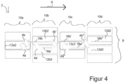
- Figure 4 shows, according to a preferred embodiment of the invention, a separation process of two piece goods 4a, 4b at different times t, t ⁇ and t", which initially together with their focus on only one conveyor 12a2 of the conveyor system 2 of Figure 3 lie on.
- the piece goods 4a, 4b are aligned obliquely to the main conveying direction 6, but since their center of gravity rests mainly on one conveyor 12, separation can be carried out analogously to that in Figure 3 take place.
- FIG. 5 shows a schematic representation of a conveyor system 2 according to the invention, which forms a separation and alignment device.
- the conveyor system 2 is subdivided into segments along the main conveying direction 6 that essentially carry out different tasks.
- the piece goods 4, 4 ' are manipulated on a widening device 18 with the aim of widening the piece goods distribution as much as possible by transporting the piece goods 4, 4' along and additionally with a movement component orthogonal to the main conveying direction 6.
- This is then carried out on a transfer conveyor 20 only a transport along the main conveying direction 6.
- the transfer conveyor 20 comprises two segments 10b, 10c, each of which only includes a single conveyor 12 spanning the entire width of the conveyor route 8.
- the alignment section 22 is essentially used to manipulate the alignment of the piece goods 4, 4 'by means of different conveying speeds 16 of the conveying means 12; for this purpose, the segments 10d - 10h are relatively short and arranged offset from one another transversely to the main conveying direction 6.
- the distance correction section 24 is essentially designed to achieve the largest possible distance between the piece goods 4, 4 'along the main conveying direction 6; for this purpose, the conveying means 12 of the distance correction section 24 are designed to be longer than those of the alignment section 22.
- Piece goods 4, 4' of different sizes are transported on the conveyor system 2, with the smaller piece goods 4' being so small that two or more piece goods 4' can rest essentially together on just one conveyor 12.
- the conveyor system 2 comprises several sensors 26 arranged above and along the conveyor path and designed as optical detectors Figure 5 Sensors 26 connected to the control unit 24, not shown, detect the position and orientation of the piece goods 4, 4 ⁇ .
- the control unit 14 controls the conveying means 12 in response to the detected position and/or orientation of the piece goods 4.
- the control unit 14 automatically calculates an optimal control of the funding means 12 using an algorithm.
- the algorithm can, but does not have to, be capable of learning, preferably capable of learning iteratively. In order to use as little computing capacity as possible, the algorithm uses its Calculation of the control of the conveying means 12, in particular those conveying means 12 on which the piece goods 4, 4 'to be separated are currently resting and the directly adjacent conveying means 12.
- the control unit 14 is adapted in this way to rotate and/or a piece of goods 4, 4 'by controlling the conveying speed 16 of the conveying means 12, in particular those conveying means 12 on which the piece of goods 4 rests, and/or the directly adjacent conveying means 12 to isolate.
Description
Die vorliegende Erfindung bezieht sich auf das technische Gebiet eines Fördersystems für Stückgüter.The present invention relates to the technical field of a conveyor system for piece goods.
Stückgüter werden auf Fördersystem entlang einer Förderstrecke transportiert, wobei eine Manipulation der entlang einer Haupttransportrichtung transportierten Stückgüter, beispielsweise Vereinzelung und/ oder Rotation, ohne eine Verwendung weiterer Vorrichtungen wie beispielsweise Ablenkblechen o.ä. erfolgt, indem die Stückgüter über mehr als ein Fördermittel transportiert werden. Für die Vereinzelung von Stückgütern im postalischen und logistischen Bereich werden Singulatoren eingesetzt, die die Stückgüter zudem teilweise noch ausrichten können.
Allerdings sind dieser und andere typische Singulatoren stets auf eine bestimmte Größe der Stückgüter ausgelegt. Eine zuverlässige Vereinzelung kann nur erreicht werden, wenn die Stückgüter größer als die Breite der Auflagefläche der Fördermittel ist. Der Markt verlangt aber mehr und mehr die Bearbeitung, Ausrichtung und Vereinzelung von Stückgütern und Sendungen mit kleineren Abmessungen. Wenn zwei kleine Stückgüter parallel nebeneinander auf einem Förderband des oben beschriebenen Singulators aufliegen, werden sie stets gemeinsam weiter transportiert und können nicht vereinzelt werden. Da die Fördermittel direkt hintereinander angeordnet und in einer Linie ausgerichtet sind, bleiben sie auch bei einer Übergabe von einem vorangehenden auf ein nachfolgendes Fördermittel stets zusammen aufliegend und können nicht einzeln von den Fördermitteln transportiert werden - auch bei individueller Ansteuerung der Fördermittel. Die dadurch nicht erfolgende Vereinzelung kann letztendlich zu einer Fehlsortierung führen. Um dieses Problem zu reduzieren, werden zusätzliche Fördermittel wie Bänder und Conveyor nach dem Singulator installiert und so versucht, die parallelen Sendungen zu separieren und vor dem Singulator zurückzuführen, was mit zusätzlichem Platzbedarf verbunden ist.However, this and other typical singulators are always designed for a specific size of piece goods. Reliable separation can only be achieved if the piece goods are larger than the width of the support surface of the conveyor. However, the market increasingly demands the processing, alignment and separation of general cargo and shipments with smaller dimensions. If two small pieces of goods lie parallel next to each other on a conveyor belt of the singulator described above, they are always transported together and cannot be separated. Since the funding is arranged directly one behind the other and in are aligned with a line, they always remain together even when transferred from a previous to a subsequent conveyor and cannot be transported individually by the conveyor - even if the conveyor is controlled individually. The resulting failure to separate can ultimately lead to incorrect sorting. In order to reduce this problem, additional conveyors such as belts and conveyors are installed after the singulator in an attempt to separate the parallel shipments and return them in front of the singulator, which requires additional space.
Das Dokument
Der vorliegenden Erfindung liegt die Aufgabe zugrunde, Stückgüter, insbesondere auch kleiner dimensionierte Stückgüter, auf einem Fördersystem zu transportieren und dabei während ihres Transports effizient zu manipulieren. Diese Aufgabe wird durch ein Fördersystem zum Transport von Stückgütern nach Anspruch 1 und durch ein Verfahren zum Transport von Stückgütern nach Anspruch 6 gelöst.The present invention is based on the object of transporting piece goods, especially smaller pieces of goods, on a conveyor system and thereby manipulating them efficiently during their transport. This object is achieved by a conveyor system for transporting piece goods according to claim 1 and by a method for transporting piece goods according to
Gemäß einem Aspekt der vorliegenden Erfindung, wird ein Fördersystem zum Transport von Stückgütern, insbesondere Postsendungen, entlang einer Hauptförderrichtung, bereitgestellt, umfassend eine Steuereinheit und eine Förderstrecke vor. Die Förderstrecke umfasst Segmente, die hintereinander entlang der Hauptförderrichtung angeordnet sind. Die Segmente umfassen im Wesentlichen parallel zueinander angeordnete Fördermittel, beispielsweise Förderbänder, die ausgestaltet sind, die Stückgüter entlang der Hauptförderrichtung zu transportieren. Die Fördermittel sind individuell antreibbar und individuell von der Steuereinheit ansteuerbar. Die Fördermittel von benachbarten Segmenten sind quer zur Hauptförderrichtung zueinander versetzt angeordnet.According to one aspect of the present invention, a conveyor system for transporting piece goods, in particular mail items, along a main conveying direction is provided, comprising a control unit and a conveying path. The conveyor line includes segments that are arranged one behind the other along the main conveying direction. The segments comprise conveying means arranged essentially parallel to one another, for example conveyor belts, which are designed to transport the piece goods along the main conveying direction. The funding can be driven individually and controlled individually by the control unit. The conveying means of neighboring segments are arranged offset from one another transversely to the main conveying direction.
Ein Segment umfasst ein oder mehr Fördermittel , die ausgestaltet sind, die Stückgüter entlang der Hauptförderrichtung zu transportieren. Ein Fördermittel eines vorangehenden Segments mündet hierbei in zwei oder mehr Fördermittel eines nachfolgenden Segments.A segment includes one or more conveyors that are designed to transport the piece goods along the main conveying direction. A funding from a previous segment leads to two or more funding from a subsequent segment.
Wenn ein Segment zwei oder mehr Fördermittel umfasst, können zwei parallel auf gleicher Höhe eines vorangehenden Segmentes übergebene Stückgüter auf unterschiedliche Fördermittel des nachfolgenden Segmentes übergeben werden. Dadurch können diese Stückgüter unterschiedlich rasch von den unterschiedlichen Fördermitteln transportiert werden und so vereinzelt werden. Aber auch wenn nur ein Stückgut übergeben wird, dieses aber auf dem nachfolgenden Segment auf zwei unterschiedlichen Fördermitteln aufliegt, kann durch unterschiedliche rasche Ansteuerung eine Veränderung der Ausrichtung erfolgen.If a segment includes two or more conveyors, two piece goods transferred in parallel at the same level in a previous segment can be transferred to different conveyors in the following segment. This means that these piece goods can be transported at different speeds by the different conveying means and can therefore be separated. But even if only one item is transferred, but it rests on two different conveyors on the following segment, the alignment can be changed by different speeds of control.
Um auf besonders einfache Weise eine Versetzung der Segmente quer zur Hauptförderrichtung zu erreichen, sind die Segmente quer zur Hauptförderrichtung zueinander versetzt angeordnet, indem die Fördermittel benachbarter Segmente zueinander versetzt angeordnet sind.In order to achieve an offset of the segments transversely to the main conveying direction in a particularly simple manner, the segments are arranged offset from one another transversely to the main conveying direction by arranging the conveying means of adjacent segments offset from one another.
Erfindungsgemäß mündet ein Fördermittel eines vorangehenden Segmentes in zwei oder mehr Fördermittel eines nachfolgenden Segmentes.According to the invention, a funding means of a preceding segment flows into two or more funding means of a subsequent segment.
Besonders einfach können dadurch auch zwei oder mehr gemeinsam auf dem Fördermittel des vorangehenden Segmentes aufliegende Stückgüter ohne Richtungsänderung auf individuell ansteuerbare Fördermittel überführt werden. So kann besonders einfach eine versetzte Anordnung auch bei Fördermitteln mit im Wesentlichen gleicher Breite erzielt werden.This makes it particularly easy to transfer two or more piece goods lying together on the conveyor of the preceding segment to individually controllable conveyors without changing direction be transferred. In this way, an offset arrangement can be achieved particularly easily, even with conveyors of essentially the same width.
Um ein möglichst unkompliziertes Fördersystem mit gleichartigen Komponenten bereitzustellen, können ein oder mehrere Segmente gleichartige Fördermittel umfassen. Bei gleichartigen Fördermitteln kann auch eine gleichartige Ansteuerung erfolgen, Aufbau und Wartung erfordern bei allen Fördermitteln die gleiche Fachkompetenz. Dies reduziert die Komplexität des Fördersystems.In order to provide a conveyor system that is as uncomplicated as possible with similar components, one or more segments can include similar conveying means. The same type of funding can also be controlled in the same way; construction and maintenance require the same expertise for all funding means. This reduces the complexity of the conveyor system.
Gemäß einer bevorzugten Ausführungsform kann das Fördersystem mindestens einen Sensor umfassen, welcher ausgestaltet ist, Position und/ oder Ausrichtung der Stückgüter zu detektieren und die Steuereinheit kann adaptiert sein, die Fördermittel in Antwort auf die detektierte Position und/ oder Ausrichtung der Stückgüter anzusteuern. So kann eine besonders effiziente, individuell auf die jeweilige Position und/ oder Ausrichtung der Stückgüter auf dem Fördersystem adaptierte Ansteuerung der Fördermittel erfolgen, die somit die Stückgüter besonders effizient manipulieren kann. Um eine erfolgreiche Vereinzelung und/ oder Ausrichtungsveränderung zu erzielen, ist keine zunächst vorliegende Standardausrichtung der Stückgüter erforderlich.According to a preferred embodiment, the conveyor system can comprise at least one sensor, which is designed to detect the position and/or orientation of the piece goods and the control unit can be adapted to control the conveying means in response to the detected position and/or orientation of the piece goods. In this way, the conveying means can be controlled particularly efficiently, individually adapted to the respective position and/or orientation of the piece goods on the conveyor system, which can therefore manipulate the piece goods particularly efficiently. In order to achieve successful separation and/or a change in orientation, an initial standard orientation of the piece goods is not necessary.
Um ein Stückgut besonders effizient zu manipulieren, kann die Steuereinheit adaptiert sein, ein Stückgut durch Kontrolle der Fördergeschwindigkeit der Fördermittel, insbesondere derjenigen Fördermittel, auf denen das Stückgut aufliegt, und/ oder der direkt angrenzenden Fördermittel, zu rotieren und/ oder zu vereinzeln. So kann eine Berechnung der zu erzielenden Rotation und/ oder Vereinzelung mit einer Rechenkapazität erfolgen, die der Komplexität der Steuereinheit angepasst ist, da sämtliche Fördermittel in die Berechnung einbezogen werden können, aber nicht müssen. Indem nur diejenigen Fördermittel, auf denen das Stückgut aufliegt und/ oder die direkt angrenzenden Fördermittel in die Berechnung einbezogen werden, wird die Berechnung mit besonders geringer Komplexität durchgeführt.In order to manipulate a piece of goods particularly efficiently, the control unit can be adapted to rotate and/or separate a piece of goods by controlling the conveying speed of the conveying means, in particular those conveying means on which the piece of goods lies and/or the directly adjacent conveying means. A calculation of the rotation and/or separation to be achieved can be carried out with a computing capacity that is adapted to the complexity of the control unit, since all funding can be included in the calculation, but does not have to be. By only including those conveyors on which the general cargo rests and/or the directly adjacent conveyors in the calculation the calculation is carried out with particularly little complexity.
Hinsichtlich eines Verfahrens wird die vorstehend genannte Aufgabe gelöst durch ein Verfahren nach Anspruch 6 zum Transportieren von Stückgütern, insbesondere Postsendungen, auf einer Förderstrecke eines Fördersystems. Die Förderstrecke umfasst Segmente, die hintereinander entlang einer Hauptförderrichtung angeordnet sind. Die Segmente umfassen im Wesentlichen parallel zueinander angeordnete Fördermittel, beispielsweise Förderbänder, die ausgestaltet sind, die Stückgüter entlang der Hauptförderrichtung zu transportieren. Die Fördermittel sind individuell antreibbar und individuell ansteuerbar. Das Verfahren umfasst die Verfahrensschritte:
- a) Transportieren eines Stückguts auf einem vorangehenden Segment;
- b) Übergeben eines Stückguts entlang der Hauptförderrichtung von einem vorangehenden Segment auf ein nachfolgendes Segment, wobei die Fördermittel der vorgenannten zwei Segmenten quer zur Hauptförderrichtung zueinander versetzt angeordnet sind; und
- c) Transportieren des Stückguts auf dem nachfolgenden Segment.
- a) transporting general cargo on a preceding segment;
- b) transferring a piece of goods along the main conveying direction from a preceding segment to a subsequent segment, the conveying means of the aforementioned two segments being arranged offset from one another transversely to the main conveying direction; and
- c) Transporting the general cargo on the following segment.
Um eine flexible Ausgestaltung des Fördersystems zu erzielen, umfasst ein Segment ein oder mehr Fördermittel, die ausgestaltet sind, die Stückgüter entlang der Hauptförderrichtung zu transportieren. So können die hintereinander angeordneten Segmente hinsichtlich der Breite und Anordnung ihrer Fördermittel sehr flexibel gestaltet werden.In order to achieve a flexible design of the conveyor system, a segment comprises one or more conveyors that are designed to transport the piece goods along the main conveying direction. The segments arranged one behind the other can be designed very flexibly with regard to the width and arrangement of their conveying means.
Um auf besonders unkomplizierte Weise eine Versetzung des nachfolgende Segment zum vorangehenden Segment zu erzielen, ist das nachfolgende Segment zum vorangehenden Segment versetzt angeordnet, indem die Fördermittel des nachfolgenden Segmentes zu den Fördermitteln des vorangehenden Segmentes zueinander versetzt angeordnet sind. So kann darüber hinaus auch bei unterschiedlich breiten Fördermitteln auf besonders einfache Weise eine Versetzung erzielt werden.In order to achieve an offset of the subsequent segment to the preceding segment in a particularly uncomplicated manner, the subsequent segment is arranged offset from the preceding segment by the conveying means of the subsequent one Segments are arranged offset from one another to the funding of the previous segment. In addition, an offset can be achieved in a particularly simple manner even with funding of different widths.
3 Erfindungsgemäß mündet ein Fördermittel des vorangehenden Segmentes in zwei oder mehr Fördermittel des nachfolgenden Segmentes. So können ein oder mehrere zunächst auf dem einen Fördermittel des vorangehenden Segmentes aufliegende Stückgüter des vorangehenden Segmentes einzig durch Bewegung in die Hauptförderrichtung auf zwei oder mehr Fördermittel des nachfolgenden Segmentes überführt werden und durch individuelle Ansteuerung dieser Fördermittel individuell weitertransportiert und somit vereinzelt und/ oder rotiert werden. Bei Anordnung der Fördermittel des vorangehenden und des nachfolgendes Segmentes in einer Linie müsste das eine oder die mehreren Stückgüter hierzu noch zusätzlich quer zur Hauptförderrichtung bewegt werden, was komplexer ausgestaltete Fördermittel und zudem eine kompliziertere Ansteuerung erfordern würde.3 According to the invention, a funding means of the preceding segment flows into two or more funding means of the following segment. Thus, one or more piece goods of the preceding segment initially resting on one conveyor of the preceding segment can be transferred to two or more conveyors of the subsequent segment solely by moving in the main conveying direction and can be further transported individually by individually controlling these conveyors and thus separated and/or rotated . If the conveying means of the preceding and subsequent segments are arranged in a line, the one or more piece goods would also have to be moved transversely to the main conveying direction, which would require more complex conveying means and also a more complicated control.
Gemäß einer bevorzugten Ausführungsform können die Fördermittel benachbarter Segmente so angeordnet sein, dass ein Stückgut von einem Fördermittel des vorangehenden Segmentes auf zwei Fördermittel des nachfolgenden Segmentes übergeben wird. So kann das eine Stückgut durch die zwei Fördermittel des nachfolgenden Segmentes transportiert und manipuliert werden, insbesondere hinsichtlich seiner Ausrichtung. Darüber hinaus ermöglicht diese Anordnung nach dem Übergeben eine besonders einfache Vereinzelung von zwei parallel auf dem Fördermittel des vorangehenden Segmentes angeordneten Stückgütern.According to a preferred embodiment, the conveying means of adjacent segments can be arranged in such a way that a piece of goods is transferred from one conveying means of the preceding segment to two conveying means of the following segment. This means that one item can be transported and manipulated by the two conveyors of the following segment, especially with regard to its orientation. In addition, this arrangement enables a particularly simple separation of two piece goods arranged in parallel on the conveyor of the previous segment after transfer.
Um eine noch gezieltere und effizientere Manipulation der Stückgüter auf dem Fördersystem zu erreichen, kann ein Detektieren von Position und/ oder Ausrichtung der Stückgüter auf dem Fördersystem und Ansteuerung der Fördermittel in Antwort auf die detektierte Position und/ oder Ausrichtung der Stückgüter erfolgen.In order to achieve even more targeted and efficient manipulation of the piece goods on the conveyor system, detection can be carried out of the position and/or orientation of the piece goods on the conveyor system and control of the conveying means in response to the detected position and/or orientation of the piece goods.
Um ein besonders effizientes Ansteuern der Fördermitteln zu ermöglichen, kann Rotieren und/ oder Vereinzeln der Stückgüter erfolgen durch Kontrollieren der Fördergeschwindigkeit der Fördermittel, insbesondere derjenigen Fördermittel, auf denen die Stückgüter aufliegen, und/ oder der direkt angrenzenden Fördermittel. Je weniger Fördermittel für das Kontrollieren hinzugezogen werden, umso weniger komplex und übersichtlicher sind Berechnung und Durchführung des Verfahrens. Um das Vereinzeln der Stückgüter, insbesondere kleiner Stückgüter, besonders einfach zu ermöglichen, involviert das Übergeben von einem vorangehenden Segment auf ein nachfolgendes Segment zwei oder mehr Fördermittel. Wenn das Stückgut so kleine Ausmaße aufweist, dass es mittig auf nur einem Fördermittel des vorangehenden Segmentes aufliegt, wird so sichergestellt, dass es so auf ein oder mehr Fördermittel des nachfolgenden Segmentes überführt wird. Bei einer ausreichend versetzten Anordnung liegt bei nur einem Fördermittel das Stückgut nun nicht mehr mittig auf dem Fördermittel des nachfolgenden Segmentes auf und kann nun manipuliert werden, bei Überführung auf zwei oder mehr Fördermitteln des nachfolgenden Segmentes kann das nun auf mehr als einem Fördermittel aufliegende Stückgut durch individuelles Antreiben dieser zwei oder mehr Fördermittel manipuliert werden.In order to enable particularly efficient control of the conveying means, rotating and/or separating the piece goods can be done by controlling the conveying speed of the conveying means, in particular those conveying means on which the piece goods rest and/or the directly adjacent conveying means. The less funding used for checking, the less complex and clearer the calculation and implementation of the procedure. In order to make it particularly easy to separate piece goods, especially small piece goods, the transfer from a previous segment to a subsequent segment involves two or more conveying means. If the piece goods are so small that they rest centrally on only one conveyor of the preceding segment, this ensures that they are transferred to one or more conveyors of the following segment. With a sufficiently offset arrangement, with only one conveyor, the piece goods are no longer centered on the conveyor of the following segment and can now be manipulated; when transferred to two or more conveyors of the subsequent segment, the piece of goods that are now resting on more than one conveyor can pass through Individually driving these two or more subsidies can be manipulated.
Bevorzugte Ausführungsformen der Erfindung werden nachfolgend anhand der Figuren beispielsweise näher erläutert. Dabei zeigen:
- Figur 1
- ein gemäß dem Stand der Technik ausgestaltetes, Segmente umfassendes Fördersystem;
Figur 2- ein erfindungsgemäßes Fördersystem mit alternierend versetzt angeordneten Segmenten;
- Figur 3
- einen Vereinzelungsvorgang zweier zunächst gemeinsam, wie in
Figur 2 Figur 4- einen Vereinzelungsvorgang zweier Stückgüter, welche zunächst gemeinsam mit ihrem Schwerpunkt auf nur einem Fördermittel des Fördersystems von
Figur 3 aufliegen; und - Figur 5
- eine schematische Darstellung eines erfindungsgemäßen Fördersystems, welches eine Vereinzelungs- und Ausrichtungsvorrichtung ausbildet.
- Figure 1
- a conveyor system comprising segments designed in accordance with the state of the art;
- Figure 2
- a conveyor system according to the invention with segments arranged alternately offset;
- Figure 3
- a process of isolating two initially together, as in
Figure 2 piece goods aligned approximately parallel to the main conveying direction and resting together on a conveyor; - Figure 4
- a separation process of two piece goods, which initially together with their focus on only one conveyor of the conveyor system
Figure 3 to lie on; and - Figure 5
- a schematic representation of a conveyor system according to the invention, which forms a separation and alignment device.
Die in diesem Fördersystem 2 dargestellten Segmente 10a - 10g sind erfindungsgemäß regelmäßig alternierend versetzt angeordnet. Durch die Hintereinanderschaltung einer Vielzahl versetzt angeordneter Segmente 10a - 10g kann an unterschiedlichen Orten der Förderstrecke 8 eine Manipulation der Stückgüter 4 erfolgen. Die Fördermittel 12 sind als Förderbänder ausgestaltet, die den Vorteil einer relativ großen und ebenen Auflagefläche bieten, zudem technisch einfach realisierbar und daher verbreitete Fördermittel 12 sind, aber auch andere Ausgestaltungen, beispielsweise Transportrollen, Transportkugeln o.ä. sind möglich. Auch eine gleichzeitige Verwendung unterschiedlich ausgestalteter Fördermittel 12 - in einem Segment 10 oder in benachbarten Segmenten - ist je nach Einsatzbereich denkbar. Um Stückgüter 4 unterschiedlicher Größe auf einem erfindungsgemäßen Fördersystem 2 zu transportieren und zu manipulieren, Z sind die Segmente (10) regelmäßig alternierend quer zur Hauptförderrichtung (6) zueinander versetzt angeordnet, indem die Fördermittel 12 benachbarter Segmente 10a, 10b zueinander versetzt angeordnet sind.The
Das in
Nach dem Überführen wird nun das Fördermittel 12b2 mit der Fördergeschwindigkeit 16b entlang der Haupttransportrichtung 6 befördert, wobei es entweder beschleunigt oder mit konstanter Überführungsgeschwindigkeit transportiert wird. Das Stückgut 4a wird auf dem Fördermittel 12b3 verzögert - entweder durch anhalten des Fördermittels 12b3 oder Betreiben mit einer geringeren Fördergeschwindigkeit 16a. Zum Zeitpunkt t` eilt somit das Stückgut 4b' dem Stückgut 4a' deutlich voran.After the transfer, the conveying means 12b2 is now conveyed at the conveying
Beide Stückgüter 4a', 4b' werden nun an das Fördermittel 12c2 übergeben, wobei das Stückgut 4b" das Fördermittel 12c2 bereits wieder verlässt als das Stückgut 4a" erst übernommen wird. Im Anschluss werden die Stückgüter 4a'', 4b" mit gleichen, vorzugsweise aber unterschiedlichen Fördergeschwindigkeiten 16a'', 16b" für eine noch bessere Vereinzelung, auf das nachfolgende Segment 10d überführt - wiederum zeitversetzt auf unterschiedliche Fördermittel 12d2, 12d3, welche ebenfalls individuell ansteuerbar sind.Both
Die Ansteuerung der Fördermittel 12a2, 12b2, 12b3, 12c2, 12d2, 12d3 erfolgt im Wesentlichen analog zur in
Auf dem Fördersystem 2 werden Stückgüter 4, 4' unterschiedlicher Größe transportiert, wobei die kleineren Stückgüter 4' so klein sind, dass zwei oder mehr Stückgüter 4' im Wesentlichen gemeinsam auf nur einem Fördermittel 12 aufliegen können.
Das Fördersystem 2 umfasst mehrere oberhalb und entlang der Förderstrecke angeordnete, als optische Detektoren ausgestaltete Sensoren 26. Die mit einer in
- 22
- Fördersystemconveyor system
- 44
- Stückgutgeneral cargo
- 66
- HauptförderrichtungMain funding direction
- 88th
- Förderstreckeconveyor line
- 1010
- Segmentsegment
- 1212
- Fördermittelfunding
- 1414
- SteuereinheitControl unit
- 1616
- Fördergeschwindigkeitconveying speed
- 1818
- Verbreiterungsvorrichtungwidening device
- 2020
- ÜberführungsfördermittelTransfer funding
- 2222
- AusrichtungsabschnittAlignment section
- 2424
- AbstandskorrekturabschnittDistance correction section
- 2626
- Sensorsensor
Claims (10)
- Conveying system (2) for transporting piece goods (4), in particular postal items, along a main conveying direction (6), comprising a control unit (14) and a conveying section (8), wherein- the conveying path (8) comprises more than two segments (10) which are arranged one behind the other along the main conveying direction (6);- the segments (10) comprise conveying means (12) arranged substantially parallel to one another, which are designed to transport the piece goods (4) along the main conveying direction (6);- the conveying means (12) are individually drivable and individually controllable by the control unit (14);- a conveying means (12) of a preceding segment (10) opens into two or more conveying means (12) of a following segment (10);- a segment (10) extends in each case over almost the entire width of the conveyor section (8),characterised in that
the segments (10) are regularly arranged alternately offset relative to one another transversely to the main conveying direction (6) in that the conveying means (12) of adjacent segments (10) are arranged offset relative to one another. - Conveyor system (2) according to claim 1, characterised in that the conveying means are designed as conveyor belts.
- Conveyor system (2) according to one of the claims 1 or 2, characterised in that one or more segments (10) comprise similar conveyor means (12).
- Conveyor system (2) according to one of the claims 1 to 3, characterised in that
the conveyor system (2) comprises at least one sensor (26) which is designed to detect the position and/or orientation of the piece goods (4), and in that the control unit (14) is adapted to control the conveyor means (12) in response to the detected position and/or orientation of the piece goods (4). - Conveyor system (2) according to one of the claims 1 to 4, characterised in that the control unit (14) is adapted to rotate and/or separate a piece goods (4) by controlling the conveying speed (16) of the conveying means (12), in particular of those conveying means (12) on which the piece goods (4) rest and/or of the directly adjacent conveying means (12).
- Method for transporting piece goods, in particular mail items, on a conveyor section (8) of a conveyor system (2), wherein- the conveyor section (8) comprises more than two segments (10) which are arranged one behind the other along a main conveying direction (6);- the segments (10) comprise conveying means (12) arranged substantially parallel to one another, which are designed to transport the piece goods (4) along the main conveying direction (6);- the conveying means (12) are individually drivable and individually controllable;- a conveying means (12) of the preceding segment (10) opens into two or more conveying means (12) of the following segment (10),comprising the steps ofa) transporting a piece of goods (4) by means of the conveying means (12) on a preceding segment (10a);b) transferring a piece of material (4) along the main conveying direction (6) from a preceding segment (10a) to a following segment (10b) arranged offset relative to this preceding segment (10a), the following segment (10) being arranged offset relative to the preceding segment (10) in that the conveying means (12) of the following segment (10) are arranged offset relative to the conveying means (12) of the preceding segment (10) and in which a segment (10) extends in each case over virtually the entire width of the conveying path (8); andc) transporting the piece goods (4) by means of the conveying means (12) on the following segment;characterised in thatthe segments (10) are regularly arranged alternately offset relative to one another transversely to the main conveying direction (6) in that the conveying means (12) of adjacent segments (10) are arranged offset relative to one another.
- Method according to claim 6, characterised in that the conveying means (12) are designed as conveyor belts.
- Method according to one of the claims 6 or 7, characterised in that the conveying means (12) of adjacent segments (10) are arranged in such a way that a piece of material (4) is transferred from one conveying means (12) of the preceding segment (10) to two conveying means (12) of the following segment (10).
- Method according to one of claims 6 to 8, characterised by detecting the position and/or orientation of the piece goods (4) on the conveyor system (2) and controlling the conveyor means (12) in response to the detected position and/or orientation of the piece goods.
- Method according to one of claims 6 to 9, characterised by rotating and/or separating the piece goods (4) by controlling the conveying speed (16) of the conveying means (12), in particular of those conveying means (12) on which the piece goods (4) rest and/or of the directly adjacent conveying means (12).
Priority Applications (3)
| Application Number | Priority Date | Filing Date | Title |
|---|---|---|---|
| EP16185726.3A EP3287396B1 (en) | 2016-08-25 | 2016-08-25 | Conveyor system with segments |
| US15/686,395 US10858199B2 (en) | 2016-08-25 | 2017-08-25 | Conveying system with segments and method for transporting individual items |
| CN201710743988.4A CN107777275B (en) | 2016-08-25 | 2017-08-25 | Transport system and method for transporting piece goods on a transport path of a transport system |
Applications Claiming Priority (1)
| Application Number | Priority Date | Filing Date | Title |
|---|---|---|---|
| EP16185726.3A EP3287396B1 (en) | 2016-08-25 | 2016-08-25 | Conveyor system with segments |
Publications (2)
| Publication Number | Publication Date |
|---|---|
| EP3287396A1 EP3287396A1 (en) | 2018-02-28 |
| EP3287396B1 true EP3287396B1 (en) | 2023-12-06 |
Family
ID=56801438
Family Applications (1)
| Application Number | Title | Priority Date | Filing Date |
|---|---|---|---|
| EP16185726.3A Active EP3287396B1 (en) | 2016-08-25 | 2016-08-25 | Conveyor system with segments |
Country Status (3)
| Country | Link |
|---|---|
| US (1) | US10858199B2 (en) |
| EP (1) | EP3287396B1 (en) |
| CN (1) | CN107777275B (en) |
Families Citing this family (10)
| Publication number | Priority date | Publication date | Assignee | Title |
|---|---|---|---|---|
| DE102017120730A1 (en) * | 2017-09-08 | 2019-03-14 | Khs Gmbh | Device and method for aligning containers |
| EP4119472A1 (en) * | 2018-11-16 | 2023-01-18 | Intelligrated Headquarters, LLC | Carton unloader for jam recovery |
| CN109879025B (en) * | 2019-03-05 | 2024-03-15 | 威海新北洋技术服务有限公司 | Side-by-side object separation method and device |
| WO2020190255A1 (en) * | 2019-03-15 | 2020-09-24 | Siemens Logistics Llc | Parcel singulation systems and methods |
| SE543415C2 (en) * | 2019-05-27 | 2021-01-12 | Itab Shop Products Ab | A conveyor system for a checkout counter |
| US10988319B2 (en) | 2019-08-01 | 2021-04-27 | Intelligrated Headquarters, Llc | Multi-belt conveyor system with removable cartridges |
| US10934101B1 (en) * | 2019-08-14 | 2021-03-02 | Intelligrated Headquarters, Llc | Systems, methods, and apparatuses, for singulating items in a material handling environment |
| US10815069B1 (en) * | 2019-08-19 | 2020-10-27 | Siemens Logistics Llc | Parcel singulation systems and methods |
| US10625952B1 (en) * | 2019-10-18 | 2020-04-21 | Grey Orange Pte. Ltd. | Induction station for conveying packages in storage facility |
| DK4053650T3 (en) * | 2021-03-01 | 2023-12-11 | Koerber Supply Chain Logistics Gmbh | COMPUTER IMPLEMENTED METHOD, DATA PROCESSING DEVICE AND COMPUTER SYSTEM FOR OPERATING A CONTROL DEVICE IN A TRANSPORTATION SYSTEM |
Citations (1)
| Publication number | Priority date | Publication date | Assignee | Title |
|---|---|---|---|---|
| US20160200525A1 (en) * | 2013-08-26 | 2016-07-14 | Bobst Mex Sa | Method and device for conveying flat objects |
Family Cites Families (7)
| Publication number | Priority date | Publication date | Assignee | Title |
|---|---|---|---|---|
| DK1556297T3 (en) | 2002-10-29 | 2008-07-21 | Siemens Ag | Transport device with handling of distributed objects |
| EP1758803A1 (en) * | 2004-06-21 | 2007-03-07 | Siemens Corporate Research, Inc. | High-rate space efficient article singulator |
| ATE420831T1 (en) * | 2004-12-03 | 2009-01-15 | Bobst Sa | APPARATUS AND METHOD FOR ALIGNING FLAT OBJECTS |
| DE102006060303B4 (en) * | 2006-12-20 | 2008-09-11 | Klaus Edelmann | sorter |
| US8127915B2 (en) * | 2009-12-21 | 2012-03-06 | Martin's Famous Pastry Shoppe, Inc. | System and method for separating a cluster of interconnected food products |
| DE102010015584A1 (en) * | 2010-04-19 | 2011-10-20 | SSI Schäfer Noell GmbH Lager- und Systemtechnik | Matrix conveyor for use as sorter or palletizer |
| US10040640B2 (en) * | 2016-05-04 | 2018-08-07 | Intelligrated Headquarters, Llc | Side-by-side reducer conveyor |
-
2016
- 2016-08-25 EP EP16185726.3A patent/EP3287396B1/en active Active
-
2017
- 2017-08-25 US US15/686,395 patent/US10858199B2/en active Active
- 2017-08-25 CN CN201710743988.4A patent/CN107777275B/en active Active
Patent Citations (1)
| Publication number | Priority date | Publication date | Assignee | Title |
|---|---|---|---|---|
| US20160200525A1 (en) * | 2013-08-26 | 2016-07-14 | Bobst Mex Sa | Method and device for conveying flat objects |
Also Published As
| Publication number | Publication date |
|---|---|
| CN107777275B (en) | 2021-04-13 |
| CN107777275A (en) | 2018-03-09 |
| US20180057271A1 (en) | 2018-03-01 |
| EP3287396A1 (en) | 2018-02-28 |
| US10858199B2 (en) | 2020-12-08 |
Similar Documents
| Publication | Publication Date | Title |
|---|---|---|
| EP3287396B1 (en) | Conveyor system with segments | |
| EP3689483B1 (en) | Device for sorting piece goods | |
| EP3248913B1 (en) | Singulation conveyor and method for conveying and separating piece goods along at least one conveying system | |
| EP3115322A1 (en) | Method and device for depalletizing tires | |
| EP3357839A1 (en) | Method and conveyor system for manipulating an original flow of goods | |
| WO2014206752A1 (en) | Conveying device for the transport and positional alignment of a unit load and sorting conveying system having such a conveying device | |
| EP3368452B1 (en) | Alignment station for aligning conveyed goods transported in a conveyor system | |
| EP3659719B1 (en) | Sorting device for articles with multiple destinations | |
| EP3786089A1 (en) | Device and method for conveying and sorting piece goods | |
| WO2003018215A1 (en) | Device for separating postal items according to thickness classes | |
| EP3904250B1 (en) | Device and method for feeding plate-shaped goods to a processing unit | |
| EP2818254B1 (en) | Device for singulating piece goods | |
| EP2743193B1 (en) | Method and device for folding a slice or a portion of a sliced food product | |
| WO2019048368A1 (en) | Device and method for orienting packages | |
| EP3196154A1 (en) | Conveying system for goods comprising an alignment device | |
| EP2945891B1 (en) | Conveying device | |
| EP3178759B1 (en) | Transport roller conveying system | |
| WO2003028908A1 (en) | Device for the separation of flat mailings into thickness classes | |
| EP3284705A1 (en) | Device and method for controlled transfer of piece goods with an alignment means | |
| DE102010035126A1 (en) | Method and device for the controlled transfer of a piece goods from a feed conveyor to a conveyor | |
| DE102018210473B4 (en) | Compact separator | |
| EP3187438B1 (en) | Conveyor system for piece goods and method for eliminating disruption in a conveyor system | |
| EP3746383A1 (en) | Device and method for conveying piece goods of a first and a second class towards a sorter | |
| EP2392213B1 (en) | Supply device for dough pieces, in particular for pre-formed dough strings used in the production of pretzels and method for supplying dough pieces | |
| DE102021201055B3 (en) | Conveyor system for elongated sample tubes |
Legal Events
| Date | Code | Title | Description |
|---|---|---|---|
| PUAI | Public reference made under article 153(3) epc to a published international application that has entered the european phase |
Free format text: ORIGINAL CODE: 0009012 |
|
| STAA | Information on the status of an ep patent application or granted ep patent |
Free format text: STATUS: THE APPLICATION HAS BEEN PUBLISHED |
|
| AK | Designated contracting states |
Kind code of ref document: A1 Designated state(s): AL AT BE BG CH CY CZ DE DK EE ES FI FR GB GR HR HU IE IS IT LI LT LU LV MC MK MT NL NO PL PT RO RS SE SI SK SM TR |
|
| AX | Request for extension of the european patent |
Extension state: BA ME |
|
| STAA | Information on the status of an ep patent application or granted ep patent |
Free format text: STATUS: REQUEST FOR EXAMINATION WAS MADE |
|
| 17P | Request for examination filed |
Effective date: 20180806 |
|
| RBV | Designated contracting states (corrected) |
Designated state(s): AL AT BE BG CH CY CZ DE DK EE ES FI FR GB GR HR HU IE IS IT LI LT LU LV MC MK MT NL NO PL PT RO RS SE SI SK SM TR |
|
| STAA | Information on the status of an ep patent application or granted ep patent |
Free format text: STATUS: EXAMINATION IS IN PROGRESS |
|
| 17Q | First examination report despatched |
Effective date: 20200514 |
|
| STAA | Information on the status of an ep patent application or granted ep patent |
Free format text: STATUS: EXAMINATION IS IN PROGRESS |
|
| RAP1 | Party data changed (applicant data changed or rights of an application transferred) |
Owner name: KOERBER SUPPLY CHAIN LOGISTICS GMBH |
|
| GRAP | Despatch of communication of intention to grant a patent |
Free format text: ORIGINAL CODE: EPIDOSNIGR1 |
|
| STAA | Information on the status of an ep patent application or granted ep patent |
Free format text: STATUS: GRANT OF PATENT IS INTENDED |
|
| INTG | Intention to grant announced |
Effective date: 20230328 |
|
| GRAS | Grant fee paid |
Free format text: ORIGINAL CODE: EPIDOSNIGR3 |
|
| P01 | Opt-out of the competence of the unified patent court (upc) registered |
Effective date: 20230523 |
|
| GRAA | (expected) grant |
Free format text: ORIGINAL CODE: 0009210 |
|
| STAA | Information on the status of an ep patent application or granted ep patent |
Free format text: STATUS: THE PATENT HAS BEEN GRANTED |
|
| AK | Designated contracting states |
Kind code of ref document: B1 Designated state(s): AL AT BE BG CH CY CZ DE DK EE ES FI FR GB GR HR HU IE IS IT LI LT LU LV MC MK MT NL NO PL PT RO RS SE SI SK SM TR |
|
| REG | Reference to a national code |
Ref country code: GB Ref legal event code: FG4D Free format text: NOT ENGLISH |
|
| REG | Reference to a national code |
Ref country code: CH Ref legal event code: EP |
|
| REG | Reference to a national code |
Ref country code: DE Ref legal event code: R096 Ref document number: 502016016254 Country of ref document: DE |
|
| REG | Reference to a national code |
Ref country code: IE Ref legal event code: FG4D Free format text: LANGUAGE OF EP DOCUMENT: GERMAN |
|
| REG | Reference to a national code |
Ref country code: NL Ref legal event code: FP |
|
| REG | Reference to a national code |
Ref country code: LT Ref legal event code: MG9D |
|
| PG25 | Lapsed in a contracting state [announced via postgrant information from national office to epo] |
Ref country code: GR Free format text: LAPSE BECAUSE OF FAILURE TO SUBMIT A TRANSLATION OF THE DESCRIPTION OR TO PAY THE FEE WITHIN THE PRESCRIBED TIME-LIMIT Effective date: 20240307 |