EP4001187A1 - Method for transverse positioning of an article to be transported - Google Patents
Method for transverse positioning of an article to be transported Download PDFInfo
- Publication number
- EP4001187A1 EP4001187A1 EP21206389.5A EP21206389A EP4001187A1 EP 4001187 A1 EP4001187 A1 EP 4001187A1 EP 21206389 A EP21206389 A EP 21206389A EP 4001187 A1 EP4001187 A1 EP 4001187A1
- Authority
- EP
- European Patent Office
- Prior art keywords
- conveyor
- unit
- another
- units
- article
- Prior art date
- Legal status (The legal status is an assumption and is not a legal conclusion. Google has not performed a legal analysis and makes no representation as to the accuracy of the status listed.)
- Pending
Links
Images


Classifications
-
- B—PERFORMING OPERATIONS; TRANSPORTING
- B65—CONVEYING; PACKING; STORING; HANDLING THIN OR FILAMENTARY MATERIAL
- B65G—TRANSPORT OR STORAGE DEVICES, e.g. CONVEYORS FOR LOADING OR TIPPING, SHOP CONVEYOR SYSTEMS OR PNEUMATIC TUBE CONVEYORS
- B65G47/00—Article or material-handling devices associated with conveyors; Methods employing such devices
- B65G47/02—Devices for feeding articles or materials to conveyors
- B65G47/04—Devices for feeding articles or materials to conveyors for feeding articles
- B65G47/06—Devices for feeding articles or materials to conveyors for feeding articles from a single group of articles arranged in orderly pattern, e.g. workpieces in magazines
- B65G47/08—Devices for feeding articles or materials to conveyors for feeding articles from a single group of articles arranged in orderly pattern, e.g. workpieces in magazines spacing or grouping the articles during feeding
- B65G47/084—Devices for feeding articles or materials to conveyors for feeding articles from a single group of articles arranged in orderly pattern, e.g. workpieces in magazines spacing or grouping the articles during feeding grouping articles in a predetermined 2-dimensional pattern
-
- B—PERFORMING OPERATIONS; TRANSPORTING
- B65—CONVEYING; PACKING; STORING; HANDLING THIN OR FILAMENTARY MATERIAL
- B65G—TRANSPORT OR STORAGE DEVICES, e.g. CONVEYORS FOR LOADING OR TIPPING, SHOP CONVEYOR SYSTEMS OR PNEUMATIC TUBE CONVEYORS
- B65G57/00—Stacking of articles
- B65G57/32—Stacking of articles characterised by stacking during transit
-
- B—PERFORMING OPERATIONS; TRANSPORTING
- B26—HAND CUTTING TOOLS; CUTTING; SEVERING
- B26D—CUTTING; DETAILS COMMON TO MACHINES FOR PERFORATING, PUNCHING, CUTTING-OUT, STAMPING-OUT OR SEVERING
- B26D3/00—Cutting work characterised by the nature of the cut made; Apparatus therefor
- B26D3/24—Cutting work characterised by the nature of the cut made; Apparatus therefor to obtain segments other than slices, e.g. cutting pies
-
- B—PERFORMING OPERATIONS; TRANSPORTING
- B26—HAND CUTTING TOOLS; CUTTING; SEVERING
- B26D—CUTTING; DETAILS COMMON TO MACHINES FOR PERFORATING, PUNCHING, CUTTING-OUT, STAMPING-OUT OR SEVERING
- B26D7/00—Details of apparatus for cutting, cutting-out, stamping-out, punching, perforating, or severing by means other than cutting
- B26D7/27—Means for performing other operations combined with cutting
- B26D7/32—Means for performing other operations combined with cutting for conveying or stacking cut product
-
- B—PERFORMING OPERATIONS; TRANSPORTING
- B65—CONVEYING; PACKING; STORING; HANDLING THIN OR FILAMENTARY MATERIAL
- B65G—TRANSPORT OR STORAGE DEVICES, e.g. CONVEYORS FOR LOADING OR TIPPING, SHOP CONVEYOR SYSTEMS OR PNEUMATIC TUBE CONVEYORS
- B65G15/00—Conveyors having endless load-conveying surfaces, i.e. belts and like continuous members, to which tractive effort is transmitted by means other than endless driving elements of similar configuration
- B65G15/30—Belts or like endless load-carriers
- B65G15/50—Endless load-carriers consisting of a series of parallel ropes or belt strips
-
- B—PERFORMING OPERATIONS; TRANSPORTING
- B65—CONVEYING; PACKING; STORING; HANDLING THIN OR FILAMENTARY MATERIAL
- B65G—TRANSPORT OR STORAGE DEVICES, e.g. CONVEYORS FOR LOADING OR TIPPING, SHOP CONVEYOR SYSTEMS OR PNEUMATIC TUBE CONVEYORS
- B65G41/00—Supporting frames or bases for conveyors as a whole, e.g. transportable conveyor frames
- B65G41/001—Supporting frames or bases for conveyors as a whole, e.g. transportable conveyor frames with the conveyor adjustably mounted on the supporting frame or base
-
- B—PERFORMING OPERATIONS; TRANSPORTING
- B65—CONVEYING; PACKING; STORING; HANDLING THIN OR FILAMENTARY MATERIAL
- B65G—TRANSPORT OR STORAGE DEVICES, e.g. CONVEYORS FOR LOADING OR TIPPING, SHOP CONVEYOR SYSTEMS OR PNEUMATIC TUBE CONVEYORS
- B65G47/00—Article or material-handling devices associated with conveyors; Methods employing such devices
- B65G47/22—Devices influencing the relative position or the attitude of articles during transit by conveyors
- B65G47/26—Devices influencing the relative position or the attitude of articles during transit by conveyors arranging the articles, e.g. varying spacing between individual articles
-
- B—PERFORMING OPERATIONS; TRANSPORTING
- B65—CONVEYING; PACKING; STORING; HANDLING THIN OR FILAMENTARY MATERIAL
- B65G—TRANSPORT OR STORAGE DEVICES, e.g. CONVEYORS FOR LOADING OR TIPPING, SHOP CONVEYOR SYSTEMS OR PNEUMATIC TUBE CONVEYORS
- B65G47/00—Article or material-handling devices associated with conveyors; Methods employing such devices
- B65G47/52—Devices for transferring articles or materials between conveyors i.e. discharging or feeding devices
- B65G47/56—Devices for transferring articles or materials between conveyors i.e. discharging or feeding devices to or from inclined or vertical conveyor sections
- B65G47/57—Devices for transferring articles or materials between conveyors i.e. discharging or feeding devices to or from inclined or vertical conveyor sections for articles
-
- B—PERFORMING OPERATIONS; TRANSPORTING
- B65—CONVEYING; PACKING; STORING; HANDLING THIN OR FILAMENTARY MATERIAL
- B65G—TRANSPORT OR STORAGE DEVICES, e.g. CONVEYORS FOR LOADING OR TIPPING, SHOP CONVEYOR SYSTEMS OR PNEUMATIC TUBE CONVEYORS
- B65G47/00—Article or material-handling devices associated with conveyors; Methods employing such devices
- B65G47/52—Devices for transferring articles or materials between conveyors i.e. discharging or feeding devices
- B65G47/68—Devices for transferring articles or materials between conveyors i.e. discharging or feeding devices adapted to receive articles arriving in one layer from one conveyor lane and to transfer them in individual layers to more than one conveyor lane or to one broader conveyor lane, or vice versa, e.g. combining the flows of articles conveyed by more than one conveyor
- B65G47/681—Devices for transferring articles or materials between conveyors i.e. discharging or feeding devices adapted to receive articles arriving in one layer from one conveyor lane and to transfer them in individual layers to more than one conveyor lane or to one broader conveyor lane, or vice versa, e.g. combining the flows of articles conveyed by more than one conveyor from distinct, separate conveyor lanes
-
- B—PERFORMING OPERATIONS; TRANSPORTING
- B26—HAND CUTTING TOOLS; CUTTING; SEVERING
- B26D—CUTTING; DETAILS COMMON TO MACHINES FOR PERFORATING, PUNCHING, CUTTING-OUT, STAMPING-OUT OR SEVERING
- B26D2210/00—Machines or methods used for cutting special materials
- B26D2210/02—Machines or methods used for cutting special materials for cutting food products, e.g. food slicers
-
- B—PERFORMING OPERATIONS; TRANSPORTING
- B65—CONVEYING; PACKING; STORING; HANDLING THIN OR FILAMENTARY MATERIAL
- B65G—TRANSPORT OR STORAGE DEVICES, e.g. CONVEYORS FOR LOADING OR TIPPING, SHOP CONVEYOR SYSTEMS OR PNEUMATIC TUBE CONVEYORS
- B65G2201/00—Indexing codes relating to handling devices, e.g. conveyors, characterised by the type of product or load being conveyed or handled
- B65G2201/02—Articles
- B65G2201/0202—Agricultural and processed food products
-
- B—PERFORMING OPERATIONS; TRANSPORTING
- B65—CONVEYING; PACKING; STORING; HANDLING THIN OR FILAMENTARY MATERIAL
- B65G—TRANSPORT OR STORAGE DEVICES, e.g. CONVEYORS FOR LOADING OR TIPPING, SHOP CONVEYOR SYSTEMS OR PNEUMATIC TUBE CONVEYORS
- B65G2201/00—Indexing codes relating to handling devices, e.g. conveyors, characterised by the type of product or load being conveyed or handled
- B65G2201/02—Articles
- B65G2201/0214—Articles of special size, shape or weigh
- B65G2201/022—Flat
Definitions
- the invention relates to slicing machines, in particular so-called slicers, with which strands of a product such as sausage or cheese that is only slightly compressible are cut into slices in the food industry.
- these strands can be produced with a cross-section that retains its shape and dimensions well, i.e. is essentially constant, over its length, they are called product calibers.
- the product calibers are pushed forward by a feed conveyor in the direction of the knife, usually on a feed conveyor pointing diagonally downwards, and are each guided through the product openings of what are known as cutting glasses, at the front end of which the protruding part of the product caliber from is cut off as a slice with the knife immediately in front of the cutting glasses.
- the slices fall onto a discharge unit, which is used to transport them away for further processing.
- the so-called portioning belt either individual slices are transported away by this portioning belt, or the portioning belt is controlled intermittently in such a way that slices cut off by one caliber are successively stored there as shingled portion in the longitudinal direction, i.e. with slices partially overlapping in the longitudinal direction.
- packs of sliced sausage or cheese are known in which such strips shingled in the longitudinal direction additionally overlap in the transverse direction as partial portions and are shingled transversely to form an entire portion.
- the two conveyor units with the article on them which are located next to one another transversely to the conveying direction, are arranged so close together according to the invention, at least at the end of their transport path in the transverse direction when viewed from above that the article projecting laterally beyond its conveyor unit projects beyond the other article on the other conveyor unit in the transverse direction, ie has an overlap in relation thereto.
- a difference in height of the support surfaces of the two conveyor units is only necessary by at least the height of the underlying article.
- the structure Since, in contrast to the prior art, the entire conveyor units do not overlap, the structure has a lower overall height and is also easier to implement.
- the two conveying units can deliver their articles in the conveying direction to a subsequent conveying unit, such as a - preferably wider - conveyor belt, preferably simultaneously, on which the two longitudinally shingled partial portions lie crosswise as a complete portion and are transported away.
- a subsequent conveying unit such as a - preferably wider - conveyor belt
- the two conveyor units with the articles ie the partial portions, are driven synchronously at the latest from the point in time at which the two articles come into contact.
- a first possibility is that the two conveyor units do not run parallel to one another when viewed from above, but rather at least in a partial area, but preferably over their entire length, with an acute intermediate angle of in particular a maximum of 30°, preferably a maximum of 20°, better a maximum of 15° to each other, especially when it comes to belt conveyors whose running directions approach each other in the transport direction.
- the overlap can be created with little structural effort.
- a second possibility is to move such a conveyor unit together with the article lying on it in the transverse direction in the direction of the other conveyor unit until the desired overlap is achieved.
- the extent of the overlap can be continuously changed and adjusted, but the structural complexity for a conveyor belt, for example, which can also be moved in a controlled manner in the transverse direction, is higher than for a conveyor belt that cannot be moved in the transverse direction.
- the two conveyor units on which the two articles were brought can not only be synchronous but also parallel after the overlap and mutual contact to each other, for which a change in the running direction is necessary for at least one of the two transport units.
- link conveyor belts or belt conveyor belts such as round belt conveyor belts
- a deflection is relatively easy, e.g. by means of a support roller with circumferential grooves in the area of the change of direction, in which the belts are received so deeply in the circumferential grooves that they can be moved despite the change in direction can't jump out.
- individual deflection rollers can also be used for each belt, the roller axis of which is at an angle to the contact surface of this belt conveyor belt, which additionally reduces friction and wear compared to the individual belts.
- the required lateral projection of an article beyond the edge of its support surface is generally achieved by placing this article in a corresponding transverse position on the conveyor unit.
- the article can make sense for the article to initially lie completely on the support surface of a conveyor unit without any lateral overhang and only then to have its lateral overhang.
- the contact surface of this conveyor unit can become narrower downstream of the point at which the article is fed, from the side where the overhang is desired, i.e. the outer edge of the contact surface can approach the transport direction .
- the preferred solution is therefore that the two conveyor units are positioned in the upstream end area with their contact surfaces at the same height and are spaced apart from one another in the transverse direction, and are only brought to the necessary height difference relative to one another along their transport route, particularly in the middle area of the transport route.
- the difference in height can be reduced again to a level where the two articles lie one on top of the other in the overlapping area.
- the two conveyor units for example belt conveyors
- the two conveyor units can also run parallel to one another from the start, which is particularly the case is possible if the two articles to be overlapped in the transverse direction are applied to the two synchronously drivable conveyor units running next to one another with a time offset, i.e. initially placed on them offset in the longitudinal direction.
- the two conveyor units are then driven at a different speed - one of the two can also stand still - until the two articles have reached the same longitudinal position, i.e. are arranged overlapping one another at different heights, then from this point in time the both conveying units are arranged synchronously again and after the height difference has been reduced or after transfer to a downstream transport unit, the two articles are shingled one on top of the other in the transverse direction as desired.
- transverse shingling is not limited to two transversely shingled articles, but also three transversely shingled articles or partial portions can form a portion, in particular by the middle article in the finished state lying at the bottom and on its two edge areas from the respective lateral edge of an article that is offset to the left and to the right of it overlaps.
- the necessary difference in height between the support surfaces depends not only on the thickness of the lower article when overlapping, but above all on how much the protruding edge area of the article only partially lying on a transport unit hangs down.
- the parameters determined can be used by the controller, for example, to automatically control the required height difference between the two support surfaces, because the less rigid the upper of the two articles is and the further it hangs down in its lateral overhang, the greater the height difference must be selected will.
- the desired extent of the overlap is usually entered manually or automatically into the controller, and is also taken into account by the controller, preferably automatically, for controlling the necessary extent of height difference.
- this initially comprises, as is known, two conveyor units lying next to one another in the transverse direction when viewed from above, whose contact surfaces at least over a certain limited area in the longitudinal direction, i.e. one of the running directions of the two conveyor units, by one Difference in height that is at least equal to the height of the article on which the other article is to rest partially.
- Such an overlapping unit comprises a controller for controlling the moving parts of this overlapping unit.
- the existing object is achieved by the overlapping unit in that, viewed from above, the conveyor units themselves are not arranged so that they overlap in the transverse direction, but rather are or can be arranged so closely next to one another over a longitudinal area of their conveying path that the only partial article lying on one of the two conveyor units can overlap the article lying on the other conveyor unit, usually lying close to its edge, to the desired extent in the transverse direction.
- the difference in height between the bearing surfaces of the two conveyor units no longer has to correspond to at least the overall height of the entire conveyor unit, as in the known solution in which the two conveyor units themselves overlap, but only by at least Height of item below after overlap or slightly more.
- the controls of such an overlapping unit shall be designed and configured to perform the prescribed transverse shingling process using that overlapping unit.
- the structural outlay for such an overlapping unit is significantly lower than in the case of the known designs.
- such an overlap unit is designed differently:
- the running directions of the two conveyor units, seen from above can be directed towards one another at an acute intermediate angle, which is preferably at most 30%, better at most 20%, better at most 15%.
- the running directions of the two conveyor units can again be aligned parallel to one another, in particular by a corresponding conveyor belt as a conveyor unit changing its running direction - which, as described above, is primarily the case with link conveyor belts or belt conveyor belts, in particular round-belt conveyor belts, is possible in a simple manner - and even more so with a conveyor unit that consists of individual conveyor carriages that can preferably be controlled independently of one another, regardless of whether they are track-guided or can be moved freely on a runway.
- the overlapping unit at least in one of the two conveyor units designed in particular as a conveyor belt, has a transverse movement device with which this conveyor unit, in particular this conveyor belt, can be moved overall in the transverse direction onto the other conveyor belt can be, on which the other article is lying over its entire surface, of course only after a corresponding difference in height between the mutual support surfaces is present.
- the overlapping unit is also designed in such a way that the two conveyor units can be driven independently of one another with regard to their conveying speed and also with regard to their stopping and restarting, for example two conveyor belts or two conveyor carriages traveling in parallel with their contact surfaces be placed at the upstream end of the transport line lying at the same level when the overlapping unit is designed in such a way that the two articles can be placed on the conveyor units at different times, from the start with the necessary lateral overlap, but spaced apart from one another in the longitudinal direction.
- the two articles can be positioned one above the other and, after reducing the height difference, immediately thereafter placed crosswise on top of each other, if necessary.
- the upper runs of the two conveyor belts can be guided differently in terms of height, i.e. they can be arranged at the same height at the beginning at the upstream end and diverged downstream therefrom in terms of height, or the The upstream ends of the two bearing surfaces are initially spaced apart in height by the required height difference.
- Such a slicing unit may be an independent machine placed in a processing line downstream of, for example, a slicing machine for slicing product calibers into slices, or it may be part of such a slicing machine.
- the existing task for a slicing machine is achieved in that it already contains an overlapping unit, in particular by having at least two of the discharge conveyors of the discharge units of such a slicing machine, which are located next to one another when viewed from above, with which the cut slices are conveyed away , which are conveyor units of the overlapping unit and are designed, arranged and controllable accordingly.
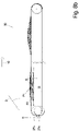
- the Figures 1a , 1b show different perspective views of a slicer 1 for the simultaneous cutting of several - only in the figures 2a , b shown - product calibers K next to each other and deposit in shingled partial portions P1, P2 each consisting of several slices S, or only individual slices S, as in Figure 2b shown with a general flow direction 10* through the slicer 1 from left to right and Figure 1c a side view of this slicer 1.
- Figure 2a shows a vertical section through such a slicer 1 with the same viewing direction as that which can be better understood by omitting side covers Figure 1c .
- the basic structure of the slicer 1 consists in that a cutting unit 7 with a rotating sickle blade 3, in this case four product calibers K lying next to one another transversely to the feed direction 10, are fed from a feed unit 20, from the front ends of which the rotating sickle blade 3 each rotates i.e. almost simultaneously, a disc S separates.
- the feed unit 20 comprises a feed conveyor 4 in the form of an endless, circulating feed belt 4, the upper strand of which can be driven at least in the feed direction 10, preferably also in the opposite direction.
- the calibers K rest on the supply belt 4 and are positioned in the transverse direction 11 by spacers 37 which protrude radially outwards from the supply belt 4 .
- the feed conveyor 4 is in the Figures 1a - c as well Figure 2a illustrated inclined position with a low-lying, cutting-side, front end and a high-lying, rear end, from which it can be folded down about a pivot axis 20' running in its width direction, the 1st transverse direction 11, which is located in the vicinity of the cutting unit 7, into an approximately horizontal loading position according to Figure 2b .
- the rear end of a caliber K lying in the feed unit 20 is held by a gripper 14a - d in a form-fitting manner with the aid of gripper claws 16 .
- grippers 14a - 14d are attached to a common gripper unit 13 which can be moved along a rod-shaped gripper guide 18 in the feed direction 10 .
- Both the feed of the gripper unit 13 and the feed conveyor 4 can be driven in a controlled manner, although the specific feed speed of the K calibers is effected by a so-called upper and lower, driven product guide 8, 9, which is located on the top and bottom of the attack the caliber K to be cut in the front end areas near the cutting unit 7:
- the front ends of the calibers K are each guided through a spectacle opening 6a-d, which is provided for each caliber and is formed in plate-shaped cutting spectacles 5.
- a spectacle opening 6a-d which is provided for each caliber and is formed in plate-shaped cutting spectacles 5.
- the cutting plane 3" is spanned by the two transverse directions 11, 12.
- the inner circumference of the spectacle openings 6a-d of the cutting edge 3a of the knife 3 serves as a shearbar.
- the two product guides 8, 9 in the first transverse direction 11 are often present separately for each caliber K and can be controlled separately.
- the upper product guide 8 can be displaceable in the second transverse direction 12—which runs perpendicular to the surface of the upper run of the feed conveyor 4 folded up into the slicing position—to adapt to the height of the caliber K in this direction. Furthermore, at least one of the product guides 8, 9 can be designed to be pivotable about one of its deflection rollers 8a, 8b, 9a, 9b in order to be able to change the direction of the strand of its conveyor belt resting on the caliber K to a limited extent.
- the obliquely spaced, just cut slices S fall onto a discharge unit 17 beginning below the cutting glasses 5, which in this case consists of several discharge conveyors 17a, b, c arranged one behind the other in the throughput direction 10* with their upper strands approximately aligned.
- an approximately horizontal residue conveyor 21 also in the form of an endlessly circulating conveyor belt, which begins with its front end below the cutting frame 5 and immediately below or behind the discharge unit 17 and with its upper run residues from transported away from there to the rear, counter to the flow direction 10*.
- At least the first conveyor 17a in the throughput direction 10* can be driven with its upper run counter to the throughput direction 10*, so that a remnant falling on it, for example, can be transported to the rear and fall onto the remnant conveyor 21 located below.
- the figures 3a , b, 4a, b show a first design of the overlapping unit 30 in plan view and in side view.
- the overlapping unit 30 has two conveyor units 27a, 27b running next to one another - which can be part of the removal unit 17 - each shown here as a belt conveyor, each with one endlessly circulating over two deflection rollers 31 Conveyor belt or conveyor belt, the upper run of which is driven from left to right in a general transport direction 10 in this case.
- the two conveyor units 27a, b do not run parallel to one another when viewed from above, but rather their conveying directions 10a, b viewed from above differ by a small intermediate angle ⁇ of generally less than 20°, so that the two conveyors 27a, b at the Beginning of their transport route, in Figure 3a left, have a distance to each other when viewed from above, but at the end of their transport route, in Figure 3a right, have a smaller distance from one another, in particular are brought together as closely as possible.
- the two conveyors 27a, b are preferably each driven by a motor 32 and are therefore driven independently of one another, with the motors 32 being controlled by a controller 30* of the overlapping unit.
- a partial portion P1 or P2 of slices S shingled in the transport direction 10 is produced or placed on the respective support surface 27a1, 27b1 of each of the two conveyor units 27a, b, which, for example, is directly from one arranged upstream of it Slicing machine can fall off, as shown in the side view of the Figure 3b shown.
- FIG. 3b also shows that the upper strands of the two conveyors, i.e. their contact surfaces 27a1, 27b1, have a height difference H to one another at the beginning of the conveyor section, i.e. at the longitudinal position of the axes of rotation of their upstream deflection rollers 31 in the transport direction.
- the downstream deflection rollers 31 and/or the upper strands of the two conveyor units 27a, b are preferably located at the same level.
- the article A in this case the partial portion P1
- the article A is placed on the lower support surface 27a1 at the start of the transport path in such a way that the article, i.e. the slices S of the partial portion P1 , as close as possible to the corresponding edge of the bearing surface 27a1 of the conveyor 27a.
- the partial portion P2 is produced or placed, preferably in the same longitudinal position, in such a way that it even protrudes in the direction of the other conveyor 27a beyond the corresponding edge of the support surface 27b1 by an overhang Ü1, for which the slices S should of course have a certain rigidity so that they do not hang down too much.
- the two articles A such as partial portions P1, P2 are moved in the transport direction 10, preferably from the start, at the same speed, i.e. synchronously, by means of the respective conveyor unit 27a, b, then they reduce their initial height difference H more and more, until they come into contact with one another close to the downstream deflection rollers 31, i.e. the end of the transport path--as in FIG Figure 4a , b shown - in that the lateral overhang Ü1 of the partial portion P2 rests on the edge region of the adjacent partial portion P1 facing it.
- downstream deflection rollers 31 or upper strands must have no or only a small enough difference in height from one another that the two partial portions are in contact with one another, ie rest on one another.
- a subsequent conveyor 26 shown here again as a belt conveyor, which is at least across the width of the entire transversely shingled Portion, here over the width of the two belt conveyors 27a, b lying next to one another in the plan view, and picks up the overlapping entire portion and transports it away.
- FIG Figure 1c in the side view an alternative solution in which both the upstream deflection rollers 31 and the two downstream deflection rollers 31 of the two conveyors 27a, b are at the same level.
- the height difference H is generated in that the upper strand of the conveyor 27b on which the laterally protruding partial portion P2 or article A is placed is guided over a further, central deflection roller 31 in the middle area of the transport section, the upper side of which moves by the height difference H positioned above the top of the downstream and/or upstream turning roller 31 of this conveyor.
- Deflection rollers 31 for a belt conveyor belt have axially spaced circumferential grooves in their outer surface, in which one of the belts 25 runs and are thus guided in a form-fitting manner against offset in the transverse direction 11 .
- the transport directions 10a, 10b of the two belt conveyor belts in the first part of their transport route again differ from one another by an intermediate angle ⁇ and towards one another in the transport direction 10, so that at the end of these differently aligned partial transport routes preferably those facing the other belt conveyor belt first belts have the same distance from each other as the belts within one of the two belt conveyor belts.
- a further deflection roller 31 with circumferential grooves for the belts 25 is arranged as a deflection device for parallel running of all belts 25 of the two belt conveyor belts 27a, b in one of the two belt conveyor units, here 27b, the grooves therein are dimensioned relative to the cross-sectional shape of the belts 25 and the belts 25 dip so deeply into it that they do not jump out of their groove despite the deflection of each belt 25 by one of the circumferential grooves in this deflection roller 31.
- the downstream deflection roller 31 at the end of the conveying path is preferably over the entire width of the two previously separate conveying units 27a, b are designed to be continuous and this is preferably also the driven deflection roller, with all circumferential grooves therein having the same spacing in the transverse direction 11 from one another.
- Such a deflection of the conveying direction of the belts of a belt conveyor belt viewed from above is all the easier possible the smaller the extent of the cross section of the individual belt 25 in the transverse direction 11 to the height of the cross section.
- a deflection with round belts is particularly easy, i.e. belts 25 with a round cross section, as in Figure 5c shown:
- the circumferential grooves for the individual belts of the conveyor 27b are not accommodated in a common deflection roller 31, but each belt 25 is deflected by its own deflection roller 34 with a circumferential groove in its circumference.
- the deflection rollers 34 are therefore generally no longer in their axial direction than the diameter of the round belt 25, and the individual deflection rollers 24 are arranged with their axes of rotation 34' parallel to one another at a distance corresponding to the distance between the round belts 25 in the transverse direction 11.
- the respective main planes of the individual deflection rollers 34 which are perpendicular to the respective axis of rotation 34' - which are also parallel to one another - are at an angle to the bearing surface 27a1 or 27b1 of the belt conveyor at this point, so that the belt 25 does not come out of the circumferential groove of the deflection roller 34 Can slip out if it is sufficiently adapted to the peripheral contour of the round belt 25 as usual.
- the Figures 6a , b, 7a, b show a fourth design of an overlapping unit 30:
- the articles A to be overlapped, here again the partial portions P1, P2, are not arranged on the bearing surface of the upper run of an endlessly circulating belt or belt conveyor, but each of the articles A, i.e.
- each of the partial portions P1, P2 on the upper side of a carriage 24a or 24b which can in particular be driven independently of one another, which in this case are track-guided, for example by having at least two guide elements each, such as a guide roller 36, protruding downwards from the underside and offset in the transport direction 10 , which are guided in a form-fitting manner in the transverse direction 11 in a track guide 23a, b that defines the respective transport direction 10a, 10b.
- a raised component such as a bar can also be used as a track guide, and conversely, counter-guide elements can be present on the carriage 24, which act on both sides of this raised track guide 23 from the outside.
- the carriages 24 can also be moved in a controlled manner on a flat surface without grooves and elevations or other form-fitting track guidance without form-fitting guidance, either with the aid of their own driven and controlled wheels or by means of another drive system.
- the two carriages 24a, b have such a distance in the transverse direction 11 that the partial portion P2, which is also placed on one of the two carriages (here 24b) with a lateral overhang Ü1, does not come into contact with the adjacent carriage 24a and the partial portion P1 placed thereon.
- the carriages 24a, b again have a height difference H with respect to their upper side, which is preferably greater than the height h of the article A, in this case the partial portion P1, which after overlapping is the lower partial portion or article .
- the carriages 24a and 24b are moved from left to right in these figures - preferably at the same speed in the transport direction 10 - they approach one another in a region of the transport directions 10a, b, which are at an angle to one another, in the transverse direction to such an extent that in the final state according to Figure 7b viewed from above, the two partial portions P1, P2 do not overlap, and viewed from the side, the two partial portions P1, P2 rest on one another at least in the overlapping area. Since the parallel guidance of the two carriages 24, 24b is possible without any problems once this overlapping state has been reached, there is no need to transfer the overlapped total portion to a subsequent conveyor.
- Another advantage of this solution is that in the initial area of the transfer unit 30, in front of the area with an angled course of the two transport directions in 10a, 10b, these two transport directions can also run parallel, and thus when creating a shingled partial portion P1, P2 each of these carriages, the longitudinal direction of the shingled portion corresponds to the transport direction 10a, 10b and the longitudinal direction of the carriage, eg 24b, in contrast to the design Figure 3a .
- the Figures 8a , b show a top view and side view of a fifth design , with the figures showing the non-overlapped initial state and the overlapped end state next to each other in the same representation:
- the conveyor units 27a, b are again shown as belt conveyors, although these two belt conveyors have transport directions 10a, b that are parallel to one another from the start.
- the overlap is achieved in that one of the belt conveyors, here 27b, including its deflection rollers 31, can be displaced in the transverse direction 11, even when the conveyor belt is running, and one of the two belt conveyors can be displaced vertically, with preferably both movement options are realized on one and the same conveyor unit, here 27b.
Abstract
Um Artikel (A) - sei es einzelne Scheiben (S) oder in Längsrichtung (10) geschindelte Teil-Portionen (P1, P2) aus Scheiben (S) - in Querrichtung (11) zur Laufrichtung (10a, b) von Förder-Einheiten (27a, b), auf denen diese Artikel (A) transportiert werden, Quer-Schindeln zu können werden nicht die beiden Förder-Einheiten (27a, b), auf denen sind je einer der beiden Artikel (A) vollflächig aufliegt, zur Überlappung gebracht zur Erzielung der Quer-Schindelung, sondern einer der Artikel (A) wird auf seiner Förder-Einheit (27a, b) mit einem seitlichen Überstand (Ü1) zur anderen Förder-Einheit (27b, a), und dem dort randseitig aufgelegten anderen Artikel (A) herantransportiert mit einer solchen Höhendifferenz, dass die beiden Artikel (A) schließlich überlappen und aufeinander abgelegt werden können, die beiden Förder-Einheiten (27a, b), jedoch lediglich hierfür eng nebeneinander geführt werden müssen ohne selbst zu überlappen. Dies vereinfacht die Bauform der Überlappungs-Einheit (30) und verringert deren Bauhöhe.About articles (A) - be it individual slices (S) or partial portions (P1, P2) of slices (S) shingled in the longitudinal direction (10) - in the transverse direction (11) to the running direction (10a, b) of conveyor units (27a, b) on which these articles (A) are transported, the two conveyor units (27a, b), on which one of the two articles (A) rests over the entire surface, are not able to overlap brought to achieve the transverse shingles, but one of the articles (A) on its conveyor unit (27a, b) with a lateral overhang (Ü1) to the other conveyor unit (27b, a), and the other placed there at the edge Article (A) transported with such a difference in height that the two articles (A) finally overlap and can be placed one on top of the other, but the two conveyor units (27a, b) only have to be guided closely next to one another for this without overlapping themselves. This simplifies the design of the overlapping unit (30) and reduces its overall height.
Description
Die Erfindung betrifft Aufschneide-Maschinen, insbesondere sogenannte Slicer, mit denen in der Lebensmittelindustrie Stränge eines nur geringfügig kompressiblen Produktes wie Wurst oder Käse in Scheiben aufgeschnitten werden.The invention relates to slicing machines, in particular so-called slicers, with which strands of a product such as sausage or cheese that is only slightly compressible are cut into slices in the food industry.
Da diese Stränge mit einem über ihre Länge gut formhaltigen und maßhaltigen, also im Wesentlichen konstanten, Querschnitt hergestellt werden können, werden sie Produkt-Kaliber genannt.Since these strands can be produced with a cross-section that retains its shape and dimensions well, i.e. is essentially constant, over its length, they are called product calibers.
Dabei werden meist mehrere Produkt-Kaliber nebeneinander gleichzeitig aufgeschnitten, indem vom gleichen Messer, welches sich in Querrichtung zur Längsrichtung der Produkt-Kaliber bewegt, in einem Durchgang jeweils eine Scheibe abgeschnitten wird.In most cases, several product calibers are cut open next to one another at the same time, in that one slice is cut off in one pass by the same knife, which moves in the transverse direction to the longitudinal direction of the product caliber.
Die Produkt-Kaliber werden von einem Zuförderer vorwärts geschoben in Richtung Messer, meist auf einem schräg nach unten gerichteten Zuförderer, und jeweils durch die Produkt-Öffnungen einer so genannten Schneidbrille geführt, an deren vorderen Ende das darüber hinaus vorstehende Teil des Produkt-Kalibers von dem Messer unmittelbar vor der Schneidbrille als Scheibe abgetrennt wird.The product calibers are pushed forward by a feed conveyor in the direction of the knife, usually on a feed conveyor pointing diagonally downwards, and are each guided through the product openings of what are known as cutting glasses, at the front end of which the protruding part of the product caliber from is cut off as a slice with the knife immediately in front of the cutting glasses.
Die Scheiben fallen in aller Regel auf eine Abförder-Einheit, mittels der sie zur Weiterverarbeitung abtransportiert werden.As a rule, the slices fall onto a discharge unit, which is used to transport them away for further processing.
Abhängig von der - intermittierenden - Ansteuerung des ersten Förderbandes dieser Abförder-Einheit, auf das die Scheiben fallen, dem sogenannten Portionierband, werden von diesem Portionierband entweder Einzelscheiben abtransportiert, oder das Portionierband wird so intermittierend angesteuert, dass von einem Kaliber abgeschnittene Scheiben dort nacheinander als in Längsrichtung geschindelte Portion, also mit sich in Längsrichtung teilweise überlappenden Scheiben, abgelegt wird.Depending on the - intermittent - control of the first conveyor belt of this removal unit onto which the slices fall, the so-called portioning belt, either individual slices are transported away by this portioning belt, or the portioning belt is controlled intermittently in such a way that slices cut off by one caliber are successively stored there as shingled portion in the longitudinal direction, i.e. with slices partially overlapping in the longitudinal direction.
Darüber hinaus sind Packungen von aufgeschnittener Wurst oder Käse bekannt, bei denen solche in Längsrichtung geschindelte Streifen als Teil-Portionen zusätzlich in Querrichtung überlappen und zu einer gesamten Portion quer-geschindelt sind.In addition, packs of sliced sausage or cheese are known in which such strips shingled in the longitudinal direction additionally overlap in the transverse direction as partial portions and are shingled transversely to form an entire portion.
Dies wird bisher meist von Hand durchgeführt oder mittels Maschinen - die dann meist nicht mehr Bestandteil der Aufschneide-Maschine sind, sondern eine separate, stromabwärts aufgestellte Maschine, die hier Überlappungs-Einheit genannt wird - bei denen die einzelnen Bänder, die die in Längsrichtung geschindelten Teil-Portionen heranführen, teilweise übereinander geführt werden und ihre Teil-Portionen auf ein darunterliegendes weiterführendes Band abwerfen und bei diesem Abwurf die in Längsrichtung geschindelten Teil-Portionen zusätzlich in Querrichtung überlappend quer geschindelt werden, wie dies beispielsweise aus der
Wegen der großen Wurfweite stellt dies immer ein erhebliches Risiko dar, und die Bau Überlappungs-Einheit baut hoch und die Steuerung sowie der Aufbau sind kompliziert.Because of the long throw, this always poses a significant risk, and the construction overlap unit is tall and complicated to control and set up.
Es ist daher die Aufgabe gemäß der Erfindung, eine solche Überlappungs-Einheit sowie eine damit ausgestattete Aufschneide-Maschine, insbesondere einen Slicer, bereitzustellen, die einfacher aufgebaut sind als bisherigen Lösungen, sowie ein Verfahren zum Betrieb einer solchen Überlappung-Einheit.It is therefore the object of the invention to provide such an overlapping unit and a slicing machine equipped with it, in particular a slicer, which have a simpler structure than previous solutions, and a method for operating such an overlapping unit.
Diese Aufgabe wird durch die Merkmale der Ansprüche 1, 11 und 15 gelöst. Vorteilhafte Ausführungsformen ergeben sich aus den Unteransprüchen.This object is solved by the features of
Hinsichtlich des Verfahrens zum Querschindeln von Einzelscheiben oder auch längsgeschindelten Teil-Portionen - vorliegend allgemein Artikel genannt -werden die beiden quer zur Förderrichtung nebeneinander befindlichen Förder-Einheiten mit dem Artikel darauf erfindungsgemäß zumindest am Ende ihrer Transportstrecke in Querrichtung in der Aufsicht betrachtet so eng nebeneinander angeordnet, dass der seitlich über seine Förder-Einheit überstehende Artikel den anderen Artikel auf der anderen Förder-Einheit in Querrichtung überragt, also demgegenüber eine Überlappung aufweist. Hierfür ist eine Höhendifferenz der Auflageflächen der beiden Förderer-Einheiten lediglich mindestens um die Höhe des tieferliegenden Artikels notwendig.With regard to the method for transverse shingling of individual slices or also longitudinally shingled partial portions - in this case generally referred to as articles - the two conveyor units with the article on them, which are located next to one another transversely to the conveying direction, are arranged so close together according to the invention, at least at the end of their transport path in the transverse direction when viewed from above that the article projecting laterally beyond its conveyor unit projects beyond the other article on the other conveyor unit in the transverse direction, ie has an overlap in relation thereto. For this purpose, a difference in height of the support surfaces of the two conveyor units is only necessary by at least the height of the underlying article.
Indem im Gegensatz zum Stand der Technik nicht die gesamten Förder-Einheiten überlappen, weist der Aufbau eine geringere Bauhöhe auf und ist auch einfacher zu realisieren.Since, in contrast to the prior art, the entire conveyor units do not overlap, the structure has a lower overall height and is also easier to implement.
Anschließend wird die Höhendifferenz zwischen den beiden Auflageflächen wieder reduziert, sodass die beiden Artikel im Überlappungsbereich in Kontakt zueinander geraten und dort aufeinander liegen.The difference in height between the two support surfaces is then reduced again so that the two articles come into contact with one another in the overlapping area and lie on top of one another there.
Sobald die Überlappung in Querrichtung hergestellt ist, also nach oder auch schon vor der Kontaktierung der beiden Artikel zueinander, können die beiden Förder-Einheiten ihre Artikel in Transportrichtung an eine nachfolgende Transport-Einheit, etwa ein - vorzugsweise breiteres - Förderband abgeben, vorzugsweise gleichzeitig, auf dem dann die beiden längsgeschindelten Teil-Portionen im quergeschindelten Zustand als gesamte Portion liegen und abtransportiert werden.As soon as the overlap has been established in the transverse direction, i.e. after or even before the two articles come into contact with one another, the two conveying units can deliver their articles in the conveying direction to a subsequent conveying unit, such as a - preferably wider - conveyor belt, preferably simultaneously, on which the two longitudinally shingled partial portions lie crosswise as a complete portion and are transported away.
Um eine Relativ-Bewegung zwischen den beiden Artikeln zu vermeiden, werden die beiden Förder-Einheiten mit den Artikeln, also den Teil-Portionen, darauf spätestens ab dem Zeitpunkt des Kontaktes der beiden Artikel synchron angetrieben.In order to avoid a relative movement between the two articles, the two conveyor units with the articles, ie the partial portions, are driven synchronously at the latest from the point in time at which the two articles come into contact.
Die Überlappung kann auf unterschiedliche Art und Weise erzielt werden:
Eine erste Möglichkeit besteht darin, dass in der Aufsicht betrachtet die beiden Förder-Einheiten nicht parallel zueinander verlaufen, sondern zumindest in einem Teilbereich, vorzugsweise aber über ihre gesamte Länge, mit einem spitzen Zwischenwinkel von insbesondere maximal 30°, besser maximal 20°, besser maximal 15° zueinander liegen, vor allem wenn es sich dabei um Gurt-Förderbänder handelt, deren Laufrichtungen sich in Transportrichtung einander annähern. Dadurch kann mit geringem baulichem Aufwand die Überlappung erzeugt werden.The overlap can be achieved in different ways:
A first possibility is that the two conveyor units do not run parallel to one another when viewed from above, but rather at least in a partial area, but preferably over their entire length, with an acute intermediate angle of in particular a maximum of 30°, preferably a maximum of 20°, better a maximum of 15° to each other, especially when it comes to belt conveyors whose running directions approach each other in the transport direction. As a result, the overlap can be created with little structural effort.
Eine zweite Möglichkeit besteht darin, eine solche Förder-Einheit samt des darauf liegenden Artikels in Querrichtung zu verfahren in Richtung der anderen Förder-Einheit, bis die gewünschte Überlappung erzielt ist.A second possibility is to move such a conveyor unit together with the article lying on it in the transverse direction in the direction of the other conveyor unit until the desired overlap is achieved.
Dadurch kann das Maß der Überlappung stufenlos geändert und eingestellt werden, jedoch ist der bauliche Aufwand für beispielsweise ein Förderband, welches zusätzlich in Querrichtung gesteuert verfahrbar ist, höher als bei einem nicht in Querrichtung verfahrbaren Förderband.As a result, the extent of the overlap can be continuously changed and adjusted, but the structural complexity for a conveyor belt, for example, which can also be moved in a controlled manner in the transverse direction, is higher than for a conveyor belt that cannot be moved in the transverse direction.
Falls eine Übergabe an eine nachfolgende Transport-Einheit nach dem Erzielen des gewünschten Maßes an Überlappung vermieden werden soll, können die beiden Förder-Einheiten, auf denen die beiden Artikel herangeführt wurden, auch ab der Überlappung und gegenseitigen Kontaktierung nicht nur synchron, sondern auch parallel zueinander weitergeführt werden, wofür eine Änderung der Laufrichtung bei mindestens einer der beiden Transport-Einheiten notwendig ist.If a transfer to a subsequent transport unit is to be avoided after the desired degree of overlap has been achieved, the two conveyor units on which the two articles were brought can not only be synchronous but also parallel after the overlap and mutual contact to each other, for which a change in the running direction is necessary for at least one of the two transport units.
Die Vermeidung der Übergabe auf eine nachgeordnete Transport-Einheit spart deren zusätzlichen Antrieb und deren Ansteuerung ein.Avoiding the transfer to a downstream transport unit saves its additional drive and control.
Ab der vertikalen Kontaktierung der Artikel liegt dann der eine Artikel ganz auf der einen Förder-Einheit und der andere, obere Artikel großenteils auf der anderen, nun parallellaufenden, Förder-Einheit, mit seinem Überlappungsbereich aber - indirekt, mit dem unteren Artikel dazwischen - auf der erstgenannten Förder-Einheit auf.From the point at which the articles are in vertical contact, one article then rests entirely on one conveyor unit and the other, upper article largely on the other, now parallel conveyor unit, but with its overlapping area - indirectly, with the lower article in between of the first-mentioned funding unit.
Mit Gurt-Förderern als Förderbänder ist eine solche Änderung der Laufrichtung, insbesondere, wenn sich davor und danach Bereiche mit gerader Laufrichtung anschließen sollen, schwer zu realisieren.With belt conveyors as conveyor belts, such a change in the direction of travel is difficult to implement, especially if areas with a straight direction of travel are to follow before and after.
Mit Glieder-Förderbändern oder Riemen-Förderbändern, etwa Rundriemen-Förderbändern, ist eine solche Umlenkung relativ einfach möglich, z.B. mittels einer Unterstützungswalze mit Umfangsnuten im Bereich der Richtungsänderung, in der die Riemen in den Umfangsnuten so tief aufgenommen sind, dass sie trotz der Richtungsänderung nicht herausspringen können. Stattdessen können auch einzelne Umlenkrollen für jeden Riemen eingesetzt werden, deren Rollenachse schräg zur Auflagefläche dieses Riemen-Förderbandes steht, was die Reibung und den Verschleiß gegenüber den einzelnen Riemen zusätzlich reduziert.With link conveyor belts or belt conveyor belts, such as round belt conveyor belts, such a deflection is relatively easy, e.g. by means of a support roller with circumferential grooves in the area of the change of direction, in which the belts are received so deeply in the circumferential grooves that they can be moved despite the change in direction can't jump out. Instead, individual deflection rollers can also be used for each belt, the roller axis of which is at an angle to the contact surface of this belt conveyor belt, which additionally reduces friction and wear compared to the individual belts.
Noch einfacher ist die Erzielung der Überlappung, wenn als Förder-Einheiten einzelne Förder-Schlitten benutzt werden, auf denen jeweils ein Artikel aufliegt und transportiert wird, da dann die Fahrtrichtung dieser Förder-Schlitten - egal ob sie formschlüssig in einer Führungs-Spur geführt werden oder frei auf dem Untergrund verfahrend gesteuert werden - sehr einfach von einer schräg aufeinander zuführenden Fahrtrichtung in parallel zueinander liegende Fahrtrichtungen geändert werden kann. Allerdings ist der bauliche Aufwand solcher, insbesondere unabhängig voneinander ansteuerbarer und verfahrbarer, Förder-Schlitten höher.Achieving the overlap is even easier if individual conveyor carriages are used as conveyor units, on each of which an article rests and is transported, since then the direction of travel of these conveyor carriages - regardless of whether they be guided in a form-fitting manner in a guide track or be controlled to move freely on the ground - can be very easily changed from a direction of travel that converges at an angle to a direction of travel that is parallel to one another. However, the structural complexity of such conveyor carriages, in particular conveyor carriages that can be controlled and moved independently of one another, is higher.
Der benötigte seitliche Überstand des einen Artikels über den Rand seiner Auflagefläche hinaus wird in aller Regel dadurch erzielt, dass dieser Artikel in einer entsprechenden Querposition auf der Förder-Einheit abgelegt wird.The required lateral projection of an article beyond the edge of its support surface is generally achieved by placing this article in a corresponding transverse position on the conveyor unit.
Je nach Anwendung kann es jedoch sinnvoll sein, dass der Artikel zunächst ohne seitlichen Überstand vollständig auf der Auflagefläche einer Förder-Einheit liegt und erst danach seinen seitlichen Überstand erhält.Depending on the application, however, it can make sense for the article to initially lie completely on the support surface of a conveyor unit without any lateral overhang and only then to have its lateral overhang.
Um hierfür keine Übergabe von einem auf einen nachfolgenden Förderer zu benötigen, kann stromabwärts der Aufgabestelle des Artikels die Auflagefläche dieser Förder-Einheit von der Seite her, an der der Überstand gewünscht wird, schmaler werden, also sich die Außenkante der Auflagefläche zur Transportrichtung hin annähern.To avoid the need for a transfer from one conveyor to a subsequent conveyor, the contact surface of this conveyor unit can become narrower downstream of the point at which the article is fed, from the side where the overhang is desired, i.e. the outer edge of the contact surface can approach the transport direction .
Dies ist beispielsweise bei Riemen-Förderbändern, die zunächst im spitzen Winkel zueinander verlaufen möglich, indem etwa bei einem Riemen-Förderband der äußerste Riemen entlang der Transportstrecke dieses Riemen-Förderbandes vor den anderen Riemen endet, also ins Rücktrum umgelenkt wird, wobei dies vom äußersten Riemen nach innen auch mit mehreren Riemen durchgeführt werden kann. Eine andere Möglichkeit besteht darin, dass sich dieser äußerste oder die mehreren äußeren Riemen eines Riemen-Förderbandes in Transportrichtung den übrigen Riemen in Querrichtung zunehmend annähern, was allerdings einen Schlupf gegenüber dem darauf aufliegenden Artikel in diesem Randbereich bewirkt.This is possible, for example, with belt conveyor belts, which initially run at an acute angle to one another, in that, for example, in the case of a belt conveyor belt, the outermost belt along the transport path of this belt conveyor belt ends in front of the other belts, i.e. it is deflected into the return strand, with this from the outermost Straps inside can also be carried out with several straps. Another possibility is that this outermost belt or the several outer belts of a belt conveyor belt in the transport direction increasingly approach the other belts in the transverse direction, which, however, causes a slippage in this edge area in relation to the article lying on it.
Die Erzielung der notwendigen Höhendifferenz zwischen den beiderseitigen Auflageflächen der beiden Förder-Einheiten kann dadurch erfolgen, dass die beidenThe achievement of the necessary height difference between the mutual support surfaces of the two conveyor units can be done in that the two
Auflageflächen bereits am stromaufwärtigen Ende mindestens diese Höhendifferenz aufwiesen, was jedoch das Beladen mit den Artikeln erschweren kann.Bearing surfaces already had at least this difference in height at the upstream end, which can, however, make loading with the articles more difficult.
Die bevorzugte Lösung besteht deshalb darin, dass die beiden Förder-Einheiten im stromaufwärtigen Endbereich mit ihren Auflageflächen auf gleicher Höhe positioniert werden, und in Querrichtung zueinander beabstandet sind, und erst entlang ihrer Transportstrecke auf die notwendige Höhendifferenz zueinander gebracht werden, insbesondere im mittleren Bereich der Transportstrecke.The preferred solution is therefore that the two conveyor units are positioned in the upstream end area with their contact surfaces at the same height and are spaced apart from one another in the transverse direction, and are only brought to the necessary height difference relative to one another along their transport route, particularly in the middle area of the transport route.
Im stromabwärtigen Endbereich kann die Höhendifferenz wieder reduziert werden bis auf ein Maß, indem die beiden Artikel im Überlappungsbereich aufeinanderliegen.In the downstream end area, the difference in height can be reduced again to a level where the two articles lie one on top of the other in the overlapping area.
Eine weitere Möglichkeit kombiniert die Erzielung der Überlappung mit der Erzielung der notwendigen Höhendifferenz der beiden Auflageflächen:
Wenn die beiden Förder-Einheiten, beispielsweise Gurt-Förderer, am stromaufwärtigen Ende mit ihren Auflageflächen auf gleicher Höhe angeordnet sind, können die beiden Förder-Einheiten, insbesondere Förderbänder, insbesondere Gurt-Förderbänder, auch von Anfang an parallel zueinander verlaufen, was insbesondere dann möglich ist, wenn die beiden in Querrichtung zu überlappenden Artikel zeitversetzt zueinander auf den beiden nebeneinander laufenden und synchron antreibbaren Förder-Einheiten aufgebracht werden, also zunächst in Längsrichtung zueinander versetzt darauf abgelegt werden.Another possibility combines the achievement of the overlap with the achievement of the necessary difference in height of the two bearing surfaces:
If the two conveyor units, for example belt conveyors, are arranged at the upstream end with their contact surfaces at the same height, the two conveyor units, in particular conveyor belts, in particular belt conveyor belts, can also run parallel to one another from the start, which is particularly the case is possible if the two articles to be overlapped in the transverse direction are applied to the two synchronously drivable conveyor units running next to one another with a time offset, i.e. initially placed on them offset in the longitudinal direction.
Dann liegt der eine Artikel über seine gesamte Breite auf der einen Förder-Einheit auf, der andere Artikel dazu in Querrichtung überlappend dahinter zum Teil auf der einen und zum Teil auf der anderen Förder-Einheit, wodurch bereits die seitliche Überlappung erzielt ist.Then one article rests over its entire width on one conveyor unit, the other article overlapping behind it in the transverse direction partly on one conveyor unit and partly on the other conveyor unit, whereby the lateral overlap is already achieved.
Wenn nun die eine Förder-Einheit mit ihrer Auflagefläche nach oben läuft, auf der der Artikel nur teilweise aufliegt, so hebt dieser Artikel von der anderen Förder-Einheit, auf der sich der andere Artikel vollständig befindet, ab. Bis zu diesem Zeitpunkt sollten die beiden Förder-Einheiten natürlich gleich schnell in Transportrichtung laufen.If one conveyor unit now runs with its contact surface up, on which the article rests only partially, this article is lifted off the other conveyor unit, on which the other article is completely located. Until this one The two conveyor units should of course run at the same speed in the transport direction at this point in time.
Wenn anschließend die beiden Förder-Einheiten mit einer Differenz-Geschwindigkeit so lange angetrieben werden - wobei eines von beiden auch stillstehen kann - bis die beiden Artikel die gleiche Längsposition erreicht haben, also einander überlappend auf unterschiedlichen Höhen angeordnet sind, so können ab diesem Zeitpunkt die beiden Förder-Einheiten wieder synchron angeordnet werden und nach Verringerung der Höhendifferenz oder nach Übergabe an eine nachgelagerte Transport-Einheit liegen die beiden Artikel wie gewünscht in Querrichtung geschindelt aufeinander.If the two conveyor units are then driven at a different speed - one of the two can also stand still - until the two articles have reached the same longitudinal position, i.e. are arranged overlapping one another at different heights, then from this point in time the both conveying units are arranged synchronously again and after the height difference has been reduced or after transfer to a downstream transport unit, the two articles are shingled one on top of the other in the transverse direction as desired.
Es sollte klar sein, dass das Querschindeln nicht auf zwei quergeschindelte Artikel begrenzt ist, sondern auch drei quergeschindelte Artikel oder Teil-Portionen eine Portion bilden können, indem insbesondere der mittlere Artikel im fertigen Zustand unten liegt und auf seinen beiden Randbereichen von dem jeweils seitlichen Rand eines links und rechts davon versetzten jeweils anderen Artikels überlappend aufliegt.It should be clear that transverse shingling is not limited to two transversely shingled articles, but also three transversely shingled articles or partial portions can form a portion, in particular by the middle article in the finished state lying at the bottom and on its two edge areas from the respective lateral edge of an article that is offset to the left and to the right of it overlaps.
Auch mehrfach als dreifach in die gleiche Richtung quergeschindelte Artikel können erzielt werden, wobei dann jedoch mit jedem weiteren Artikel der benötigte seitliche Versatz für das Erzielen der Überlappung vom Auflegen auf seine Förder-Einheit bis zur Kontaktierung des benachbarten Artikels zunimmt, was die Realisierung erschwert.Articles that are cross-shingled several times as three times in the same direction can also be achieved, but then with each additional article the lateral offset required to achieve the overlap from placing on its conveyor unit to contacting the adjacent article increases, which makes implementation more difficult.
Die notwendige Höhendifferenz zwischen den Auflageflächen hängt nicht nur von der Dicke des beim Überlappen unteren Artikels ab, sondern vor allem auch davon, wie stark der überstehende Randbereich des nur teilweise auf einer Transport-Einheit aufliegenden Artikels herabhängt.The necessary difference in height between the support surfaces depends not only on the thickness of the lower article when overlapping, but above all on how much the protruding edge area of the article only partially lying on a transport unit hangs down.
Da dies von der Steifigkeit des Artikels und diese von weiteren physikalischen Parametern wie etwa der Temperatur und Konsistenz des Artikels abhängt, werden vorzugsweise die relevanten physikalischen Parameter der Artikel, zumindest des nach Überlappung oben liegenden Artikels, ermittelt, beispielsweise
- die Biegesteifigkeit des Artikels um eine in Laufrichtung gerichtete Achse,
und / oder - dessen Temperatur,
und / oder - dessen Gewicht,
und / oder - dessen Wassergehalt, ableitbar aus seiner elektrischen Leitfähigkeit.
- the flexural rigidity of the article about an axis directed in the direction of travel,
and or - its temperature
and or - its weight,
and or - its water content, which can be derived from its electrical conductivity.
Die ermittelten Parameter können von der Steuerung dazu benutzt werden, um beispielsweise automatisch die benötigte Höhendifferenz zwischen den beiden Auflageflächen zu steuern, denn je weniger biegesteif der obere der beiden Artikel ist und je weiter dieser in seinem seitlichen Überstand herabhängt, umso größer muss die Höhendifferenz gewählt werden.The parameters determined can be used by the controller, for example, to automatically control the required height difference between the two support surfaces, because the less rigid the upper of the two articles is and the further it hangs down in its lateral overhang, the greater the height difference must be selected will.
Das gewünschte Maß der Überlappung wird dagegen in der Regel manuell oder automatisch in die Steuerung eingegeben, und wird von der Steuerung, vorzugsweise automatisch, ebenfalls zum Steuern des notwendigen Maßes an Höhendifferenz mitberücksichtigt.The desired extent of the overlap, on the other hand, is usually entered manually or automatically into the controller, and is also taken into account by the controller, preferably automatically, for controlling the necessary extent of height difference.
Hinsichtlich der Überlappungs-Einheit zum Quer-Schindeln von Artikeln umfasst diese zunächst bekanntermaßen zwei in der Aufsicht betrachtet in Querrichtung nebeneinanderliegende Förder-Einheiten, deren Auflageflächen zumindest über einen bestimmten begrenzten Bereich in Längsrichtung, also einer der Laufrichtungen der beiden Förder-Einheiten, um eine Höhendifferenz auseinanderliegen, die mindestens der Höhe des Artikels entspricht, auf dem der andere Artikel teilweise aufliegen soll.With regard to the overlapping unit for transverse shingling of articles, this initially comprises, as is known, two conveyor units lying next to one another in the transverse direction when viewed from above, whose contact surfaces at least over a certain limited area in the longitudinal direction, i.e. one of the running directions of the two conveyor units, by one Difference in height that is at least equal to the height of the article on which the other article is to rest partially.
Ferner umfasst eine solche Überlappungs-Einheit eine Steuerung zur Steuerung der beweglichen Teile dieser Überlappungs-Einheit.Furthermore, such an overlapping unit comprises a controller for controlling the moving parts of this overlapping unit.
Erfindungsgemäß wird die bestehende Aufgabe durch die Überlappungs-Einheit gelöst, indem in der Aufsicht betrachtet die Förder-Einheiten selbst in Querrichtung nicht überlappend angeordnet sind, sondern lediglich über einen Längsbereich ihrer Förderstrecke so eng nebeneinander angeordnet sind oder angeordnet werden können, dass der nur teilweise auf einem der beiden Förder-Einheiten aufliegende Artikel den auf der anderen Förder-Einheit aufliegenden, meist nahe an dessen Rand aufliegenden, Artikel im gewünschten Maß in Querrichtung überlappen kann.According to the invention, the existing object is achieved by the overlapping unit in that, viewed from above, the conveyor units themselves are not arranged so that they overlap in the transverse direction, but rather are or can be arranged so closely next to one another over a longitudinal area of their conveying path that the only partial article lying on one of the two conveyor units can overlap the article lying on the other conveyor unit, usually lying close to its edge, to the desired extent in the transverse direction.
Auf diese Art und Weise muss die Höhendifferenz zwischen den Auflageflächen der beiden Förder-Einheiten nicht mehr mindestens der Bauhöhe der gesamten Förder-Einheit entsprechen wie bei der bekannten Lösung, in der die beiden Förder-Einheiten selbst einander überlappen, sondern nur noch um mindestens die Höhe des nach Überlappung unten liegenden Artikels oder etwas mehr.In this way, the difference in height between the bearing surfaces of the two conveyor units no longer has to correspond to at least the overall height of the entire conveyor unit, as in the known solution in which the two conveyor units themselves overlap, but only by at least Height of item below after overlap or slightly more.
Die Steuerung einer solchen Überlappungs-Einheit muss dazu bestimmt sein und entsprechend ausgelegt sein, das vorgeschriebene Verfahren zum Querschindeln mit Hilfe dieser Überlappungs-Einheit durchzuführen.The controls of such an overlapping unit shall be designed and configured to perform the prescribed transverse shingling process using that overlapping unit.
Der bauliche Aufwand für eine solche Überlappungs-Einheit ist wesentlich geringer als bei den Bekannten Bauformen. Je nachdem, wie die notwendige Höhendifferenz erzielt wird oder ob eine anschließende Übergabe an eine andere Transport-Einheit unmittelbar nach Herstellen der Überlappung gewünscht ist, ist eine solche Überlappungs-Einheit unterschiedlich ausgebildet:
In einer Ausführungsform können die Laufrichtungen der beiden Förder-Einheiten in der Aufsicht betrachtet in einem spitzen Zwischenwinkel aufeinander zugerichtet sein, der vorzugsweise maximal 30%, besser maximal 20%, besser maximal 15% beträgt.The structural outlay for such an overlapping unit is significantly lower than in the case of the known designs. Depending on how the necessary height difference is achieved or whether a subsequent transfer to another transport unit is desired immediately after the overlap has been created, such an overlap unit is designed differently:
In one embodiment, the running directions of the two conveyor units, seen from above, can be directed towards one another at an acute intermediate angle, which is preferably at most 30%, better at most 20%, better at most 15%.
Wenn sich dabei die Auflageflächen um die benötigte Höhendifferenz versetzt zueinander befinden, wird durch dieses aneinander Annähern der beiden Förder-Einheiten in Transportrichtung die Überlappung auf einfache Art und Weise erzeugt.If the bearing surfaces are offset from one another by the required height difference, the overlap is produced in a simple manner by this approaching of the two conveyor units in the transport direction.
Danach, also nach Erzielen der seitlichen Überlappung, können die Laufrichtungen der beiden Förder-Einheiten wieder parallel zueinander ausgerichtet sein, insbesondere indem ein entsprechendes Förderband als Förder-Einheit seine Laufrichtung ändert - was wie vorbeschrieben vor allem bei Glieder-Förderbändern oder Riemen-Förderbändern, insbesondere Rundriemen-Förderbändern, auf einfache Art und Weise möglich ist - und erst recht bei einer Förder-Einheit, die aus einzelnen, vorzugsweise unabhängig voneinander steuerbaren, Förder-Schlitten besteht, egal ob diese spurgeführt sind oder auf einer Fahrfläche frei verfahrbar sind.After that, i.e. after the lateral overlap has been achieved, the running directions of the two conveyor units can again be aligned parallel to one another, in particular by a corresponding conveyor belt as a conveyor unit changing its running direction - which, as described above, is primarily the case with link conveyor belts or belt conveyor belts, in particular round-belt conveyor belts, is possible in a simple manner - and even more so with a conveyor unit that consists of individual conveyor carriages that can preferably be controlled independently of one another, regardless of whether they are track-guided or can be moved freely on a runway.
Eine Änderung der Laufrichtungen der beiden Förder-Einheiten ist nicht notwendig, wenn diese von Anfang an auch in dem Bereich, in dem die Überlappung der beiden darauf liegenden Artikel hergestellt wird, parallel zueinander verlaufen.It is not necessary to change the running directions of the two conveyor units if they also run parallel to one another from the start in the area in which the overlapping of the two articles lying on them is produced.
Dies ist dann möglich, wenn die Überlappungs-Einheit zumindest bei einer der beiden, insbesondere als Förderband ausgebildeten, Förder-Einheiten eine Querverfahr-Vorrichtung besitzt, mit der diese Förder-Einheit, insbesondere dieses Förderband, insgesamt in Querrichtung auf das andere Förderband zu verfahren werden kann, auf dem der andere Artikel vollflächig liegt, natürlich erst nachdem eine entsprechende Höhendifferenz zwischen den beiderseitigen Auflageflächen vorhanden ist.This is possible if the overlapping unit, at least in one of the two conveyor units designed in particular as a conveyor belt, has a transverse movement device with which this conveyor unit, in particular this conveyor belt, can be moved overall in the transverse direction onto the other conveyor belt can be, on which the other article is lying over its entire surface, of course only after a corresponding difference in height between the mutual support surfaces is present.
Wenn die Überlappungs-Einheit ferner so ausgebildet ist, dass die beiden Förder-Einheiten hinsichtlich ihrer Förder-Geschwindigkeit und auch hinsichtlich ihres Anhaltens und Wieder-Ingangsetzens unabhängig voneinander antreibbar sind, können beispielsweise zwei Förderbänder oder auch zwei parallel fahrende Förder-Schlitten mit ihren Auflageflächen am stromaufwärtigen Ende der Transportstrecke auf gleicher Höhe liegend angeordnet sein, wenn die Überlappungs-Einheit so ausgebildet ist, dass die beiden Artikel zeitversetzt auf die Förder-Einheiten abgelegt werden können und zwar von Anfang an mit der notwendigen seitlichen Überlappung, aber in Längsrichtung voneinander beabstandet.If the overlapping unit is also designed in such a way that the two conveyor units can be driven independently of one another with regard to their conveying speed and also with regard to their stopping and restarting, for example two conveyor belts or two conveyor carriages traveling in parallel with their contact surfaces be placed at the upstream end of the transport line lying at the same level when the overlapping unit is designed in such a way that the two articles can be placed on the conveyor units at different times, from the start with the necessary lateral overlap, but spaced apart from one another in the longitudinal direction.
Dann können nach Herstellen der Höhendifferenz zwischen den Auflageflächen die beiden Artikel übereinander positioniert und nach Reduzieren der Höhendifferenz bei Bedarf unmittelbar danach wieder auf einander quergeschindelt abgelegt werden.Then, after the height difference between the support surfaces has been established, the two articles can be positioned one above the other and, after reducing the height difference, immediately thereafter placed crosswise on top of each other, if necessary.
Zur Erzielung der Höhendifferenz können bei der Ausbildung der Förder-Einheiten als Band-Einheiten die Obertrume der beiden Förderbänder hinsichtlich der Höhe unterschiedlich geführt werden, also bei Beginn am stromaufwärtigen Ende auf der gleichen Höhe angeordnet und stromabwärts davon hinsichtlich der Höhe auseinandergeführt werden, oder die stromaufwärtigen Enden der beiden Auflageflächen sind von Anfang an um die benötigte Höhendifferenz zueinander beabstandet in der Höhe.To achieve the difference in height, when the conveyor units are designed as belt units, the upper runs of the two conveyor belts can be guided differently in terms of height, i.e. they can be arranged at the same height at the beginning at the upstream end and diverged downstream therefrom in terms of height, or the The upstream ends of the two bearing surfaces are initially spaced apart in height by the required height difference.
Eine solche Überlappungs-Einheit kann eine selbstständige Maschine sein, die in einer Verarbeitungslinie stromabwärts der z.B. Aufschneide-Maschine zum Aufschneiden von Produkt-Kalibern in Scheiben angeordnet ist, oder sie kann Bestandteil einer solchen Aufschneide-Maschine sein.Such a slicing unit may be an independent machine placed in a processing line downstream of, for example, a slicing machine for slicing product calibers into slices, or it may be part of such a slicing machine.
Dann wird die bestehende Aufgabe für eine Aufschneide-Maschine dadurch gelöst, dass diese eine Überlappungs-Einheit bereits enthält, insbesondere indem wenigstens zwei der in der Aufsicht betrachtet nebeneinanderliegenden Abförderer der Abförder-Einheiten einer solche Aufschneide-Maschine, mit der die abgetrennten Scheiben abgefördert werden, die Förder-Einheiten der Überlappungs-Einheit sind und entsprechend ausgebildet, angeordnet sowie ansteuerbar sind.Then the existing task for a slicing machine is achieved in that it already contains an overlapping unit, in particular by having at least two of the discharge conveyors of the discharge units of such a slicing machine, which are located next to one another when viewed from above, with which the cut slices are conveyed away , which are conveyor units of the overlapping unit and are designed, arranged and controllable accordingly.
Ausführungsformen gemäß der Erfindung sind im Folgenden beispielhaft näher beschrieben. Es zeigen:
- Figuren 1a, b:
- eine Aufschneide-Maschine in Form eines Slicers gemäß dem Stand der Technik in unterschiedlichen perspektivischen Ansichten,
- Figuren 1c:
- die Aufschneide-Maschine der
Figuren 1a , b in der Seitenansicht, - Figuren 2a:
- einen vereinfachten vertikalen Längsschnitt durch die Aufschneide-Maschine der
Figuren 1a - c, also in gleicher Blickrichtung wieFigur 1c , in dem die verschiedenen Förderbänder besser zu erkennen sind, mit in die Aufschneidestellung hochgeklapptem Zufuhrband, - Figuren 2b:
- einen Längsschnitt gemäß
Figur 2a , aber mit in die Beladestellung herabgeklapptem Zufuhrband und fortgeschrittenem Aufschneidezustand des Produkt-Kalibers, Figur 3a, b:- eine erste Bauform einer Überlappungseinheit in Aufsicht und Seitenansicht am Beginn des Überlappungsvorganges,
- Figur 3c:
- eine Seitenansicht einer alternativen zweiten Bauform,
- Figur 4a, b:
- die erste Bauform der Überlappungseinheit in Aufsicht und Seitenansicht am Ende des Überlappungsvorganges,
- Figur 5a, b:
- eine dritte Bauform einer Überlappungseinheit in Aufsicht und Seitenansicht am Beginn des Überlappungsvorganges,
- Figur 5c:
- eine andere Bauform der Umlenkeinheit,
Figur 6a, b:- eine vierte Bauform einer Überlappungseinheit in Aufsicht und Seitenansicht am Beginn des Überlappungsvorganges,
- Figur 7a, b:
- die vierte Bauform der Überlappungseinheit in Aufsicht und Seitenansicht am Ende des Überlappungsvorganges,
- Figur 8a, b:
- eine fünfte Bauform der Überlappungseinheit in Aufsicht und Seitenansicht.
- Figures 1a, b:
- a slicing machine in the form of a slicer according to the prior art in different perspective views,
- Figures 1c:
- the slicing machine
Figures 1a , b in side view, - Figures 2a:
- a simplified vertical longitudinal section through the slicing machine
Figures 1a - c , i.e. in the same viewing direction asFigure 1c , in which the different conveyor belts can be seen better, with the infeed belt folded up into the slicing position, - Figures 2b:
- according to a longitudinal section
Figure 2a , but with the infeed conveyor folded down into the loading position and the product caliber slicing in an advanced state, - Figure 3a, b:
- a first design of an overlapping unit in top view and side view at the beginning of the overlapping process,
- Figure 3c:
- a side view of an alternative second design,
- Figure 4a, b:
- the first design of the overlapping unit in top view and side view at the end of the overlapping process,
- Figure 5a, b:
- a third design of an overlapping unit in top view and side view at the beginning of the overlapping process,
- Figure 5c:
- a different design of the deflection unit,
- Figure 6a, b:
- a fourth design of an overlapping unit in top view and side view at the beginning of the overlapping process,
- Figure 7a, b:
- the fourth design of the overlapping unit in top view and side view at the end of the overlapping process,
- Figure 8a, b:
- a fifth design of the overlapping unit in top view and side view.
Die
Der Grundaufbau des Slicers 1 besteht darin, dass einer Schneideinheit 7 mit einem rotierenden Sichelmesser 3 in diesem Fall vier quer zur Zufuhrrichtung 10 nebeneinanderliegende Produkt-Kaliber K von einer Zufuhreinheit 20 zugeführt werden, von deren vorderen Enden das rotierende Sichelmesser 3 jeweils bei einer Umdrehung, also quasi gleichzeitig, eine Scheibe S abtrennt.The basic structure of the
Die Zufuhreinheit 20 umfasst einen Zuförderer 4 in Form eines endlosen, umlaufenden Zufuhr-Bandes 4, dessen Obertrum zumindest in Zufuhrrichtung 10, vorzugsweise auch entgegen hierzu antreibbar ist. Die Kaliber K liegen auf dem Zufuhr-Band 4 auf und sind in Querrichtung 11 durch Abstandhalter 37 positioniert, die vom Zufuhr-Band 4 nach radial außen abstehen.The
Für das Aufschneiden der Produkt-Kaliber K befindet sich der Zuförderer 4 in der in den
Das hintere Ende eines in der Zufuhreinheit 20 liegenden Kalibers K ist jeweils von einem Greifer 14a - d formschlüssig mit Hilfe von Greiferklauen 16 gehalten.The rear end of a caliber K lying in the
Diese Greifer 14a - 14d sind an einer gemeinsamen Greifer-Einheit 13 befestigt, welche entlang einer stangenförmigen Greifer-Führung 18 in Zufuhrrichtung 10 verfahren werden kann.These
Dabei ist sowohl der Vorschub der Greifer-Einheit 13 als auch der Zuförderer 4 gesteuert antreibbar, wobei jedoch die konkrete Zufuhrgeschwindigkeit der Kaliber K durch eine sogenannte obere und untere, angetriebene Produkt-Führung 8, 9 bewirkt wird, die an der Oberseite und Unterseite der aufzuschneidenden Kaliber K in deren vorderen Endbereichen nahe der Schneideinheit 7 angreifen:
Die vorderen Enden der Kaliber K sind jeweils durch eine für jedes Kaliber vorhandene Brillenöffnung 6a - d geführt, die in einer plattenförmigen Schneidbrille 5 ausgebildet sind. Unmittelbar vor der vorderen, schräg nach unten weisenden Stirnfläche der Schneidbrille 5 verläuft die Schneidebene 3", in der das Sichelmesser 3 mit seiner Schneidkante 3a rotiert und damit den Überstand der Kaliber K aus der Schneidbrille 5 als Scheibe S abtrennt. Die Schneidebene 3" wird von den beiden Querrichtungen 11, 12 aufgespannt.Both the feed of the
The front ends of the calibers K are each guided through a spectacle opening 6a-d, which is provided for each caliber and is formed in plate-shaped
Dabei dient der Innenumfang der Brillenöffnungen 6a - d der Schneidkante 3a des Messers 3 als Gegenschneide.The inner circumference of the
Häufig sind die beiden Produktführungen 8, 9 in der ersten Querrichtung 11 separat für jedes Kaliber K vorhanden und separat ansteuerbar.The two
Die obere Produktführung 8 kann in der zweiten Querrichtung 12 - die lotrecht zur Fläche des Obertrums des in die Aufschneidestellung hochgeklappten Zuförderers 4 verläuft - verlagerbar sein zur Anpassung an die Höhe des Kalibers K in dieser Richtung. Ferner kann mindestens eine der Produktführungen 8, 9 um eine ihrer Umlenkrollen 8a, 8b, 9a, 9b verschwenkbar ausgebildet sein, um die Richtung des am Kaliber K anliegenden Trumes ihres Förderbandes begrenzt verändern zu können.The
Die schräg im Raum stehenden, gerade abgetrennten, Scheiben S fallen auf eine unterhalb der Schneidbrille 5 beginnende Abförder-Einheit 17, die in diesem Fall aus in Durchlaufrichtung 10* mehreren mit ihren Obertrumen etwa fluchtend hintereinander angeordneten Abförderern 17a, b, c besteht.The obliquely spaced, just cut slices S fall onto a
Unterhalb der Zuförder-Einheit 20 befindet sich ein etwa horizontal verlaufender Resteförderer 21 ebenfalls in Form eines endlos umlaufenden Förderbandes, welcher mit seinem vorderen Ende unterhalb der Schneidbrille 5 und unmittelbar unter oder hinter der Abförder-Einheit 17 beginnt und mit seinem Obertrum darauf fallende Reste von dort aus entgegen der Durchlaufrichtung 10* nach hinten abtransportiert.Below the
Deshalb kann zumindest der in Durchlaufrichtung 10* erste Förderer 17a mit seinem Obertrum entgegen der Durchlaufrichtung 10* angetrieben werden, sodass ein darauf fallendes z.B. Reststück nach hinten transportiert werden kann und auf den tiefer liegenden Reste-Förderer 21 fällt.Therefore, at least the
Die
Wie
Vorzugsweise sind die beiden Förderer 27a, b von jeweils einem Motor 32 und damit unabhängig voneinander angetrieben, wobei die Motore 32 von einer Steuerung 30* der Überlappungs-Einheit gesteuert werden.The two
Auf am Beginn der Transportstrecke, wird auf der jeweilige Auflagefläche 27a1, 27b1 jedes der beiden Förder-Einheiten 27a, b eine Teil-Portion P1 bzw. P2 von in Transportrichtung 10 geschindelten Scheiben S erzeugt oder aufgelegt, die beispielsweise direkt von einer stromaufwärts davon angeordneten Aufschneide-Maschine herabfallen können, wie in der Seitenansicht der
Wie
Vorzugsweise befinden sich die stromabwärtigen Umlenkwalzen 31 und/oder die Obertrume der beiden Förder-Einheiten 27a, b auf der gleichen Höhe.The
Für die Überlappung wird der Artikel A, in diesem Fall die Teil-Portion P1, auf der am Anfang der Transportstrecke tiefer liegenden Auflagefläche 27a1 so aufgelegt, dass zur anderen Förder-Einheit 27b hin der Artikel, also die Scheiben S der Teil-Portion P1, möglichst nah am entsprechenden Rand der Auflagefläche 27a1 des Förderers 27a liegen.For the overlapping, the article A, in this case the partial portion P1, is placed on the lower support surface 27a1 at the start of the transport path in such a way that the article, i.e. the slices S of the partial portion P1 , as close as possible to the corresponding edge of the bearing surface 27a1 of the
Auf der anderen Auflagefläche 27b1 dagegen wird die Teil-Portion P2, vorzugsweise an der gleichen Längsposition, so erzeugt oder aufgelegt, dass sie in Richtung des anderen Förderers 27a über den entsprechenden Rand der Auflagefläche 27b1 sogar um einen Überstand Ü1 vorsteht, wofür die Scheiben S natürlich eine gewisse Steifigkeit besitzen sollten, damit sie nicht zu stark nach unten herabhängen.On the other support surface 27b1, on the other hand, the partial portion P2 is produced or placed, preferably in the same longitudinal position, in such a way that it even protrudes in the direction of the
Wenn die beiden Artikel A wie Teil-Portionen P1, P2, vorzugsweise von Anfang an, mit der gleichen Geschwindigkeit, also synchron, in Transportrichtung 10 bewegt werden mittels der jeweiligen Förder-Einheit 27a, b so verringern sie ihre anfängliche Höhendifferenz H immer mehr, bis sie nahe an den stromabwärtigen Umlenkwalzen 31, also dem Ende der Transportstrecke, in Kontakt zueinander geraten - wie in
Hierfür dürfen die stromabwärtigen Umlenkwalzen 31 oder Obertrume keinen oder eine nur so geringe Höhendifferenz zueinander aufweisen, dass die beiden Teil-Portionen in Kontakt zueinanderstehen, also aufeinander aufliegen. Dies ist im Übrigen auch deshalb notwendig, da sich in aller Regel stromabwärts der beiden nebeneinander laufenden Förder-Einheiten 27a, b ein nachfolgender Förderer 26, hier wieder dargestellt als Gurt-Förderer, befindet, der sich mindestens über die Breite der gesamten quer-geschindelten Portion, hier über die Breite der beiden nebeneinander in der Aufsicht liegenden Gurtförderer 27a, b, erstreckt und die überlappende gesamte Portion aufnimmt und abtransportiert.For this purpose, the
Für den Fall, dass die unterschiedliche Höhenlage der Anfänge der beiden Förder-Einheiten 27a, b Probleme bereitet, zeigt
Die in den
Werden - wie in
Umlenkwalzen 31 für ein Riemen-Förderband besitzen in ihrer Mantelfläche axial beabstandet Umfangsnuten, in denen jeweils einer der Riemen 25 läuft und dadurch formschlüssig gegen Versatz in Querrichtung 11 geführt sind.Be - as in
Wie
An dieser Umlenk-Stelle ist als Umlenk-Vorrichtung zum Parallellauf aller Riemen 25 der beiden Riemen-Förderbänder 27a, b in einer der beiden Riemen-Fördereinheiten, hier 27b, eine weitere Umlenkwalze 31 mit Umfangsnuten für die Riemen 25 angeordnet, wobei darin die Nuten relativ zur Querschnittsform der Riemen 25 so dimensioniert sind und die Riemen 25 darin so tief eintauchen, dass sie trotz der Umlenkung jedes Riemens 25 durch jeweils eine der Umfangsnuten in dieser Umlenkwalze 31 nicht aus ihrer Nut herausspringen.At this deflection point, a
Die stromabwärtige Umlenkwalze 31 am Ende der Förderstrecke ist vorzugsweise über die gesamte Breite der beiden vorher getrennten Förder-Einheiten 27a, b durchgehend ausgebildet und dies ist vorzugsweise auch die angetriebene Umlenkwalze, wobei alle Umfangsnuten darin den gleichen Abstand in Querrichtung 11 zueinander aufweisen.The
Auf diese Art und Weise kann eine Übergabe an einen nachfolgenden Förderer 26 ab der Position der Überlappung der beiden Teil-Portionen P1, P2 vorerst vermieden werden und erst bei Bedarf wesentlich weiter stromabwärts eine Übergabe an eine nächste Einheit erfolgen.In this way, a transfer to a
Eine solche in der Aufsicht betrachtete Umlenkung der Förderrichtung der Riemen eines Riemen-Förderbandes ist umso einfacher möglich, je kleiner die Erstreckung des Querschnittes des einzelnen Riemens 25 in Querrichtung 11 zur Höhe des Querschnittes ist.Such a deflection of the conveying direction of the belts of a belt conveyor belt viewed from above is all the easier possible the smaller the extent of the cross section of the
Besonders einfach ist eine Umlenkung mit Rundriemen möglich, also Riemen 25 mit rundem Querschnitt, wie in
Die Umfangsnuten für die einzelnen Riemen des Förderers 27b sind dabei nicht in einer gemeinsamen Umlenkwalze 31 untergebracht, sondern jeder Riemen 25 wird durch eine eigene Umlenkrolle 34 mit Umfangsnut in ihrem Umfang umgelenkt. Die Umlenkrollen 34 sind damit in ihrer axialen Richtung in aller Regel nicht länger als der Durchmesser des Rundriemens 25, und die einzelnen Umlenkrollen 24 sind mit parallelem Verlauf ihrer Rotationsachsen 34' zueinander mit einem Abstand entsprechend dem Abstand der Rundriemen 25 in Querrichtung 11 angeordnet. Dabei stehen die auf der jeweiligen Rotationsachse 34' lotrecht stehenden jeweiligen Hauptebenen der einzelnen Umlenkrollen 34 - die ebenfalls parallel zueinander liegen - schräg zur Auflagefläche 27a1 bzw. 27b1 des Riemen-Förderers an dieser Stelle, sodass der Riemen 25 aus der Umfangsnut der Umlenkrolle 34 nicht herausrutschen können, wenn diese wie üblich an die Umfangskontur des Rundriemens 25 ausreichend angepasst ist.A deflection with round belts is particularly easy, i.e.
The circumferential grooves for the individual belts of the
Die
Dabei werden die zu überlappenden Artikel A, hier wiederum die Teil-Portionen P1, P2, nicht auf der Auflagefläche des Obertrums eines endlos umlaufenden Gurt- oder Riemen-Förderers angeordnet, sondern jeder der Artikel A, also hier jede der Teil-Portionen P1, P2 auf der Oberseite eines - insbesondere unabhängig voneinander antreibbaren - Schlittens 24a bzw. 24b angeordnet, die in diesem Fall spurgeführt sind, indem sie z.B. von der Unterseite nach unten abragend und in Transportrichtung 10 versetzt jeweils mindestens zwei Führungselemente wie etwa je eine Führungsrolle 36 aufweisen, die in Querrichtung 11 formschlüssig in einer die jeweilige Transportrichtung 10a, 10b vorgebenden Spurführung 23a, b geführt sind.the
The articles A to be overlapped, here again the partial portions P1, P2, are not arranged on the bearing surface of the upper run of an endlessly circulating belt or belt conveyor, but each of the articles A, i.e. here each of the partial portions P1, P2 on the upper side of a
Selbstverständlich kann als Spurführung auch ein erhabenes Bauteil wie eine Leiste verwendet werden, und umgekehrt am Schlitten 24 Führungs-Gegenelemente vorhanden sein, die beidseits von außen an dieser erhabene Spurführung 23 angreifen. Ebenso können die Schlitten 24 auch ohne formschlüssige Führung auf einer ebenen Fläche ohne Nuten und Erhebungen oder anderer formschlüssiger Spurführung gesteuert verfahrbar sein, sei es mit Hilfe eigener angetriebener und gesteuerter Räder oder mittels eines anderen Antriebssystems.Of course, a raised component such as a bar can also be used as a track guide, and conversely, counter-guide elements can be present on the carriage 24, which act on both sides of this raised track guide 23 from the outside. Likewise, the carriages 24 can also be moved in a controlled manner on a flat surface without grooves and elevations or other form-fitting track guidance without form-fitting guidance, either with the aid of their own driven and controlled wheels or by means of another drive system.
Analog zu der ersten Bauform der
In dieser Ausgangslage besitzen die Schlitten 24a, b hinsichtlich ihrer Oberseite wiederum eine Höhedifferenz H, die vorzugsweise größer ist als die Höhe h des Artikels A, in diesem Fall der Teil-Portion P1, die nach Überlappung die untere Teil-Portion bzw. Artikel ist.In this initial position, the
Wie in
Indem die Schlitten 24a bzw. 24b - vorzugsweise mit gleicher Geschwindigkeit in Transportrichtung 10 - in diesen Figuren von links nach rechts gefahren werden, nähern sie sich in einem Bereich der winklig zueinander stehenden Transportrichtungen 10a, b in Querrichtung soweit aneinander an, dass im Endzustand gemäß
Ein weiterer Vorteil dieser Lösung besteht darin, dass im Anfangsbereich der Übergabe-Einheit 30, vor dem Bereich mit winkeligem Verlauf der beiden Transportrichtung in 10a, 10b, diese beiden Transportrichtungen ebenfalls parallel verlaufen können, und damit beim Erzeugen einer geschindelten Teilportion P1, P2 auf jedem dieser Schlitten die Längsrichtung der geschindelten Teilportion mit der Transportrichtung 10a, 10b und der Längsrichtung des Schlittens, z.B. 24b, übereinstimmt, im Gegensatz zu der Bauform bei
Die
Dabei werden als Förder-Einheiten 27a, b in diesem Fall wiederum als Gurt-Förderer dargestellt, wobei diese beiden Gurt-Förderer jedoch von Anfang an zueinander parallele Transportrichtungen 10a, b aufweisen.the
In this case, the
Die Überlappung wird in diesem Fall dadurch erzielt, dass einer der Gurt-Förderer, hier 27b, einschließlich seiner Umlenkwalzen 31 in Querrichtung 11 verlagerbar ist, auch im laufenden Zustand des Förderbandes, und einer der beiden Gurt-Förderer in der Höhe verlagerbar ist, wobei vorzugsweise beide Bewegungsmöglichkeiten an ein und derselben Förder-Einheit, hier 27b, realisiert sind.In this case, the overlap is achieved in that one of the belt conveyors, here 27b, including its
Dies kann erreicht werden, indem die Umlenkwalzen 31 dieses verlagerbaren Förderers 27b in einem umgebenden Traggestell, beispielsweise einem Rahmen 35, aufgenommen sind, der auch den Antrieb für diesen Förderer 27b tragen kann, und die gesamte Einheit - häufig als Förder-Kassette bezeichnet - sowohl in Querrichtung 11 als auch in der Höhe mittels nicht dargestellter gesteuerter Antriebe zur Transportrichtung 10 verlagerbar ist.This can be achieved by accommodating the
Wenn somit die im Anfangsbereich der Transportstrecke mit Höhenabstand und Seitenabstand auf den beiden Förderern 27a, b aufgelegten Teil-Portionen P1, P2 durch Verlagerung beispielsweise desjenigen Förderers 27b, auf den die Teil-Portion P2 mit seitlichem Überstand Ü1 aufliegt, zunächst in Querrichtung verlagert und anschließend abgesenkt wird bis zur Kontaktierung der beiden Teil-Portionen P1, P2, ist die Überlappung mit dem gewünschten Maß Ü2 an Überlappung erzielt.Thus, if the partial portions P1, P2 placed on the two
- 11
- Aufschneide-Maschine, SlicerSlicing machine, slicer
- 1*1*
- Steuerungsteering
- 22
- Grundgestellbase frame
- 33
- Messerknife
- 33
- Rotationsachseaxis of rotation
- 3"3"
- Messerebene, Schneidebeneknife level, cutting level
- 3a3a
- Schneidkantecutting edge
- 44
- Zuförderer, Zufuhr-BandInfeed conveyor, infeed belt
- 55
- Schneidbrillecutting glasses
- 6a - d6a - d
- Brillen-Öffnungeyeglass opening
- 77
- Schneideinheitcutting unit
- 88th
- obere Produktführung, oberes Führungsbandupper product guide, upper guide belt
- 8.18.1
- Kontakt-Trum, Unter-TrumContact strand, lower strand
- 8a8a
- Brillen-seitige UmlenkrolleGlasses-side pulley
- 8b8b
- Brillen-abgewandte UmlenkrolleGlasses-averted pulley
- 99
- untere Produktführung, unteres Führungsbandlower product guide, lower guide belt
- 8.18.1
- Kontakt-Trum, Ober-Trumcontact run, upper run
- 9a9a
- Brillen-seitige UmlenkrolleGlasses-side pulley
- 9b9b
- Brillen-abgewandte UmlenkrolleGlasses-averted pulley
- 1010
- Transportrichtung, Längsrichtung, axiale RichtungTransport direction, longitudinal direction, axial direction
- 10a, b10a, b
- Transportrichtungtransport direction
- 10*10*
- Durchlaufrichtung durch MaschineDirection of flow through machine
- 1111
- 1. Querrichtung (Breite Slicer)1. Cross Direction (Width Slicer)
- 1212
- 2. Querrichtung (Höhen-Richtung Kaliber)2. Transverse direction (elevation direction caliber)
- 1313
- Greifer-Einheit, Greifer-SchlittenGripper unit, gripper carriage
- 14,14 a - d14:14a-d
- Greifergripper
- 1515
- Querstegcross bar
- 15'15'
- Auflageflächebearing surface
- 1616
- Greifer-KlaueGrab Claw
- 1717
- Abförder-Einheitdischarge unit
- 17a, b, c17a,b,c
- Portionierband, AbfördererPortioning belt, discharge conveyor
- 1818
- Greifer-Führunggripper guide
- 1919
- Höhen-Sensorheight sensor
- 2020
- Zufuhreinheitfeeding unit
- 2121
- Reststück-Fördererremnant conveyor
- 2222
- Reststück-Behälterremnant bin
- 2323
- Spurführungtracking
- 2424
- Transportschlittentransport carriage
- 2525
- Riemenbelt
- 2626
- nachfolgende Transport-Einheitsubsequent transport unit
- 27a, b27a, b
- Förder-Einheitconveyor unit
- 27a127a1
- Auflageflächebearing surface
- 27b127b1
- Auflageflächebearing surface
- 27a', 27b'27a', 27b'
- Laufrichtungrunning direction
- 2828
- Umlenk-Vorrichtungdeflection device
- 2929
- Querverfahr-Vorrichtungtraversing device
- 3030
- Überlappungs-Einheitoverlap unit
- 3131
- Umlenk-Walzedeflection roller
- 3232
- Motorengine
- 3333
- Umfangsnutcircumferential groove
- 3434
- Umlenk-Rolleidler pulley
- 34'34'
- Rotationsachseaxis of rotation
- 3535
- Rahmenframe
- 3636
- Führungselement, FührungsrolleGuiding element, guiding role
- αa
- Zwischenwinkelintermediate angle
- AA
- Artikelarticle
- hH
- Höhe Artikelheight article
- HH
- Höhendifferenz FördererHeight difference conveyor
- KK
- Produkt, Produkt-Kaliberproduct, product caliber
- KRKR
- Reststück, Kaliber-ReststückRemnant, caliber remnant
- SS
- Scheibedisc
- PP
- Portionportion
- P1, P2P1, P2
- Teil-Portionportion serving
- Ü1U1
- ÜberstandGot over
- Ü2U2
- Überlappungoverlap
- VV
- Verpackungselementpacking element
Claims (15)
indem
in which
dadurch gekennzeichnet, dass
characterized in that
dadurch gekennzeichnet, dass
characterized in that
dadurch gekennzeichnet, dass
das Übergeben an die nachfolgende Transport-Einheit (26)
characterized in that
the transfer to the following transport unit (26)
dadurch gekennzeichnet, dass
spätestens ab dem Zeitpunkt des Kontaktes der beiden Artikel (A) die beiden Förder-Einheiten (27a, b) synchron angetrieben werden.
(Schräges Annähern der Abförder-Einheiten:)Method according to one of the preceding claims,
characterized in that
the two conveyor units (27a, b) are driven synchronously at the latest from the point in time at which the two articles (A) come into contact.
(Oblique approach of the discharge units:)
dadurch gekennzeichnet, dass
characterized in that
dadurch gekennzeichnet, dass
characterized in that
dadurch gekennzeichnet, dass
characterized in that
dadurch gekennzeichnet, dass
characterized in that
dadurch gekennzeichnet, dass
zumindest die für die beschriebene Vorgehensweise relevanten physikalischen Parameter der in Querrichtung zu überlappenden Artikel (A), insbesondere
und/oder
und/oder
ermittelt werden oder bekannt sind und für die Berechnung der Höhendifferenz (H) und/oder des Maßes (Ü2) der Überlappung berücksichtigt werden.
characterized in that
at least the physical parameters of the articles (A) to be overlapped in the transverse direction that are relevant for the described procedure, in particular
and or
and or
are determined or are known and are taken into account for the calculation of the height difference (H) and/or the dimension (Ü2) of the overlap.
dadurch gekennzeichnet, dass
characterized in that
dadurch gekennzeichnet, dass
characterized in that
dadurch gekennzeichnet, dass
characterized in that
Applications Claiming Priority (1)
| Application Number | Priority Date | Filing Date | Title |
|---|---|---|---|
| DE102020129750.5A DE102020129750A1 (en) | 2020-11-11 | 2020-11-11 | Method for transverse positioning of an article to be transported |
Publications (1)
| Publication Number | Publication Date |
|---|---|
| EP4001187A1 true EP4001187A1 (en) | 2022-05-25 |
Family
ID=78528670
Family Applications (1)
| Application Number | Title | Priority Date | Filing Date |
|---|---|---|---|
| EP21206389.5A Pending EP4001187A1 (en) | 2020-11-11 | 2021-11-04 | Method for transverse positioning of an article to be transported |
Country Status (3)
| Country | Link |
|---|---|
| US (1) | US11718484B2 (en) |
| EP (1) | EP4001187A1 (en) |
| DE (1) | DE102020129750A1 (en) |
Families Citing this family (1)
| Publication number | Priority date | Publication date | Assignee | Title |
|---|---|---|---|---|
| DE102022113919A1 (en) | 2022-06-02 | 2023-12-07 | Multivac Sepp Haggenmüller Se & Co. Kg | Needle-bearing deflection roller and slicing machine equipped with it |
Citations (3)
| Publication number | Priority date | Publication date | Assignee | Title |
|---|---|---|---|---|
| US20040016331A1 (en) * | 2002-07-26 | 2004-01-29 | Formax, Inc. | Automatic draft length compensation for slicing machine system |
| DE102014106400A1 (en) * | 2014-04-25 | 2015-11-12 | Weber Maschinenbau Gmbh Breidenbach | INDIVIDUAL TRANSPORT OF FOOD PORTIONS |
| DE102015104055A1 (en) | 2015-03-18 | 2016-09-22 | Textor Maschinenbau GmbH | overlapping means |
Family Cites Families (11)
| Publication number | Priority date | Publication date | Assignee | Title |
|---|---|---|---|---|
| US4645061A (en) * | 1985-02-26 | 1987-02-24 | Welch Hubert E | Machine for stacking nestable extruded cans |
| DE3773478D1 (en) * | 1986-12-10 | 1991-11-07 | Thurne Eng Co Ltd | CONVEYOR SYSTEM. |
| DE3726254A1 (en) | 1987-08-07 | 1989-02-16 | Hans Schiessl | Transition conveying section for leading together, leading apart, sorting or channelling objects being transported in a conveying installation |
| DE4220602C2 (en) | 1992-04-29 | 2001-02-22 | Maschb Heinrich Hajek Gmbh & C | Cutting machine for cutting food products with a length-adjustable conveyor belt |
| US6935215B2 (en) * | 2002-08-14 | 2005-08-30 | Formax, Inc. | Slicing machine and conveyor system with automatic product width compensation |
| US7104388B2 (en) * | 2004-08-26 | 2006-09-12 | Arr Tech, Inc. | Conveyor system for stacked product |
| DE102013206138A1 (en) * | 2013-04-08 | 2014-10-09 | Weber Maschinenbau Gmbh Breidenbach | Apparatus for completing a format set of products |
| DE102013223494A1 (en) * | 2013-11-18 | 2015-05-21 | Robert Bosch Gmbh | Product power transfer device |
| DE102014113738A1 (en) | 2014-09-23 | 2016-03-24 | Weber Maschinenbau Gmbh Breidenbach | DEVICE FOR COMBINING PORTIONS |
| DE102017100620A1 (en) | 2017-01-13 | 2018-07-19 | Weber Maschinenbau Gmbh Breidenbach | product gripper |
| EP3927624A4 (en) * | 2019-02-19 | 2022-11-23 | Provisur Technologies, Inc. | Multi-presentation slicing conveyor apparatus |
-
2020
- 2020-11-11 DE DE102020129750.5A patent/DE102020129750A1/en active Pending
-
2021
- 2021-11-04 EP EP21206389.5A patent/EP4001187A1/en active Pending
- 2021-11-10 US US17/523,159 patent/US11718484B2/en active Active
Patent Citations (3)
| Publication number | Priority date | Publication date | Assignee | Title |
|---|---|---|---|---|
| US20040016331A1 (en) * | 2002-07-26 | 2004-01-29 | Formax, Inc. | Automatic draft length compensation for slicing machine system |
| DE102014106400A1 (en) * | 2014-04-25 | 2015-11-12 | Weber Maschinenbau Gmbh Breidenbach | INDIVIDUAL TRANSPORT OF FOOD PORTIONS |
| DE102015104055A1 (en) | 2015-03-18 | 2016-09-22 | Textor Maschinenbau GmbH | overlapping means |
Also Published As
| Publication number | Publication date |
|---|---|
| DE102020129750A1 (en) | 2022-05-12 |
| US20220144559A1 (en) | 2022-05-12 |
| US11718484B2 (en) | 2023-08-08 |
Similar Documents
| Publication | Publication Date | Title |
|---|---|---|
| EP2420362B1 (en) | Method and device for cutting food products | |
| EP2671829B1 (en) | Expander device | |
| EP3170632B1 (en) | Method and device for cutting food products | |
| EP2420364B1 (en) | Portion completion with multi-track cutting | |
| EP3136867A1 (en) | Method and device for creating blanks from pieces of dough from one or more webs of dough | |
| EP3246260B1 (en) | Device for feeding product holders and device for pivoting a cover section of a product holder | |
| DE2702724C2 (en) | Device for sorting and storing blanks in panel dividing systems | |
| EP0867263A2 (en) | Product feeding system for a slicer | |
| EP4001187A1 (en) | Method for transverse positioning of an article to be transported | |
| EP0694019B1 (en) | Device for releasing a product from a continuously circulating belt | |
| EP3277605B1 (en) | Trough-type conveyor for transporting fish transversely to the longitudinal extent thereof in the transport direction, arrangement and method | |
| DE102019100631B3 (en) | sorter | |
| WO2002070164A1 (en) | Device for cutting metal strips to length | |
| DE69723654T2 (en) | Apparatus and method for forming a continuous strip of dough | |
| EP3380419B1 (en) | Method and device for portioning slices of food with change of shape, in particular folding, of the portion | |
| DE4413008A1 (en) | Folding device for sheet layers | |
| EP4032669A1 (en) | Multi-track cutting machine with independently controllable grippers | |
| EP4000829A1 (en) | Method for positioning an item to be transported and device for performing the method | |
| EP2298514B1 (en) | Method and device for cutting a length of food into slices | |
| EP1683612A1 (en) | Method and device for transporting flexible flat products, and for cutting them at the same time | |
| EP2984009B1 (en) | System for the time-limited storage of objects | |
| EP2609023A1 (en) | Method and device for transferring a piece good in a monitored manner from a supply conveyor to a conveyor | |
| EP0739834A2 (en) | Turning device for articles during transport | |
| DE19959333B4 (en) | Device for separating strips and uses of such a device | |
| DE102004056018A1 (en) | Conveyor system with collector system, comprises collector system with numerous staple positions lying next to one another in row, and number of utility tracks on which row of staples can be simultaneously collectable |
Legal Events
| Date | Code | Title | Description |
|---|---|---|---|
| PUAI | Public reference made under article 153(3) epc to a published international application that has entered the european phase |
Free format text: ORIGINAL CODE: 0009012 |
|
| STAA | Information on the status of an ep patent application or granted ep patent |
Free format text: STATUS: THE APPLICATION HAS BEEN PUBLISHED |
|
| STAA | Information on the status of an ep patent application or granted ep patent |
Free format text: STATUS: REQUEST FOR EXAMINATION WAS MADE |
|
| AK | Designated contracting states |
Kind code of ref document: A1 Designated state(s): AL AT BE BG CH CY CZ DE DK EE ES FI FR GB GR HR HU IE IS IT LI LT LU LV MC MK MT NL NO PL PT RO RS SE SI SK SM TR |
|
| 17P | Request for examination filed |
Effective date: 20220517 |
|
| RBV | Designated contracting states (corrected) |
Designated state(s): AL AT BE BG CH CY CZ DE DK EE ES FI FR GB GR HR HU IE IS IT LI LT LU LV MC MK MT NL NO PL PT RO RS SE SI SK SM TR |
|
| STAA | Information on the status of an ep patent application or granted ep patent |
Free format text: STATUS: EXAMINATION IS IN PROGRESS |
|
| 17Q | First examination report despatched |
Effective date: 20230525 |
|
| P01 | Opt-out of the competence of the unified patent court (upc) registered |
Effective date: 20230519 |