EP3178593B1 - Wälzfräser und verfahren zum herstellen und betreiben eines wälzfräsers - Google Patents
Wälzfräser und verfahren zum herstellen und betreiben eines wälzfräsers Download PDFInfo
- Publication number
- EP3178593B1 EP3178593B1 EP15198488.7A EP15198488A EP3178593B1 EP 3178593 B1 EP3178593 B1 EP 3178593B1 EP 15198488 A EP15198488 A EP 15198488A EP 3178593 B1 EP3178593 B1 EP 3178593B1
- Authority
- EP
- European Patent Office
- Prior art keywords
- cooling
- base body
- coolant
- hob
- hob according
- Prior art date
- Legal status (The legal status is an assumption and is not a legal conclusion. Google has not performed a legal analysis and makes no representation as to the accuracy of the status listed.)
- Active
Links
Images


Classifications
-
- B—PERFORMING OPERATIONS; TRANSPORTING
- B23—MACHINE TOOLS; METAL-WORKING NOT OTHERWISE PROVIDED FOR
- B23F—MAKING GEARS OR TOOTHED RACKS
- B23F21/00—Tools specially adapted for use in machines for manufacturing gear teeth
- B23F21/12—Milling tools
- B23F21/16—Hobs
-
- B—PERFORMING OPERATIONS; TRANSPORTING
- B23—MACHINE TOOLS; METAL-WORKING NOT OTHERWISE PROVIDED FOR
- B23C—MILLING
- B23C5/00—Milling-cutters
- B23C5/28—Features relating to lubricating or cooling
-
- B—PERFORMING OPERATIONS; TRANSPORTING
- B23—MACHINE TOOLS; METAL-WORKING NOT OTHERWISE PROVIDED FOR
- B23F—MAKING GEARS OR TOOTHED RACKS
- B23F17/00—Special methods or machines for making gear teeth, not covered by the preceding groups
- B23F17/003—Special methods or machines for making gear teeth, not covered by the preceding groups for dry cutting
-
- Y—GENERAL TAGGING OF NEW TECHNOLOGICAL DEVELOPMENTS; GENERAL TAGGING OF CROSS-SECTIONAL TECHNOLOGIES SPANNING OVER SEVERAL SECTIONS OF THE IPC; TECHNICAL SUBJECTS COVERED BY FORMER USPC CROSS-REFERENCE ART COLLECTIONS [XRACs] AND DIGESTS
- Y02—TECHNOLOGIES OR APPLICATIONS FOR MITIGATION OR ADAPTATION AGAINST CLIMATE CHANGE
- Y02P—CLIMATE CHANGE MITIGATION TECHNOLOGIES IN THE PRODUCTION OR PROCESSING OF GOODS
- Y02P70/00—Climate change mitigation technologies in the production process for final industrial or consumer products
- Y02P70/10—Greenhouse gas [GHG] capture, material saving, heat recovery or other energy efficient measures, e.g. motor control, characterised by manufacturing processes, e.g. for rolling metal or metal working
Definitions
- the invention relates to a hob with a cylindrical base body, on the circumference of which a plurality of cutting teeth is formed.
- the invention also relates to a method for operating such a hob.
- Hobs have a mostly cylindrical base body, on the circumference of which a large number of cutting teeth are formed. The cutting teeth are used for machining a workpiece.
- a hob is known from, for example DE 44 45 911 C1 .
- an open cooling channel system is provided, through which a coolant is passed through the hob and exits through openings on the circumference of the base body between cutting inserts spaced in the circumferential direction.
- the cooling channel system is introduced by drilling.
- the geometry of the cooling duct system can only be varied within narrow limits, since the direction of the drilled cooling ducts cannot be changed easily.
- the cooling effect achieved by an open cooling channel system of the type described is also not always sufficient.
- a hob which is made up of several disk-shaped segments. Each segment has a central through-hole, which lies on the axis of rotation of the hob, the through-holes jointly forming a line for a coolant. This cooling line can be closed.
- US 2013/0302098 A1 shows the preamble of claim 1.
- a hob is known with an axial clamping section for clamping in a machine tool.
- a tool for a machine tool that has a coolant channel that runs completely inside and extends between a coolant inlet and a coolant outlet, the coolant inlet and the coolant outlet being connectable to a coolant circuit of the machine tool.
- the object of the invention is to provide a hob and methods of the type mentioned at the beginning, wherein a cooling duct system with an optimized and flexibly configurable cooling effect is provided.
- the invention achieves the object in that a closed cooling channel system for a coolant is formed in the base body, with a coolant supply opening arranged on an end face of the base body and a coolant discharge opening also arranged on an end face of the base body, which is Cooling channel system extends over the axial extent of the base body, an open cooling channel system for a coolant separate from the closed cooling channel system being formed in the base body with a coolant supply opening arranged on an end face of the base body and a plurality of outlet openings in the area of the cutting teeth.
- the hob according to the invention has a cylindrical base body, on the circumference of which a plurality of cutting teeth are formed, in particular in one piece with the base body.
- the cutting teeth can be arranged, for example, in a helical pattern over the circumference of the base body.
- Exchangeable inserts can be attached to the cutting teeth.
- a closed cooling channel system is provided in the hob. Except for the coolant supply opening and the coolant discharge opening, this cooling channel system therefore has no further openings, in particular no outlet openings on the circumference of the base body in the region of the cutting teeth.
- the coolant supply opening and the coolant discharge opening can in particular be arranged on the same end face of the base body.
- this relates to the direction of flow of the coolant in the cooling channel system. This is predetermined by the coolant supply opening, through which the coolant is introduced into the cooling duct system, and the coolant discharge opening, via which the coolant is discharged from the cooling duct system.
- the closed cooling duct system ensures optimal cooling.
- An individually adapted geometry of the channels of the cooling channel system can ensure that all areas of the cooling system that are to be cooled Hob must be sufficiently tempered at all times. Reliable temperature control of the hob can ensure high machining speeds. The process can also be kept dry at the cutting point, which is desirable in some applications.
- the channels of the closed cooling channel system can have a circular cross section, for example. However, this is not mandatory.
- the coolant to be conducted through the cooling channel system can in particular be a cooling liquid, for example oil and / or water.
- the base body can comprise an axial clamping section for clamping the hob in a machine tool, the cooling channel system comprising a supply channel running helically in the base body around the axial clamping section, which is connected to the coolant supply opening and the coolant discharge opening.
- the cutting teeth can be arranged along a helical shape on the circumference of the base body and the helical shape of the supply channel can correspond to the helical shape of the cutting tooth arrangement.
- the clamping section can, for example, be an axial bore for receiving a drive shaft of the machine tool. However, it can also be an axial extension, which is correspondingly received in a receptacle of the machine tool.
- the cutting teeth in hob cutters are arranged helically along a helix around the circumference of the base body. If, according to the above configuration, the helix shape of the supply channel corresponds to the helix shape of the cutting tooth arrangement, the supply channel extends below each cutting tooth, which optimizes the cooling effect.
- a plurality of cooling channels can branch off from the supply channel, the cooling channels each passing through a cutting tooth and then re-opening into the supply channel.
- Each cooling channel is assigned to a cutting tooth that it passes through.
- the branching and re-confluence into the supply channel can be provided within the base body, in particular in each case under the assigned cutting tooth.
- the cooling ducts are arranged, at least in sections, within the respective cutting tooth, where they ensure targeted temperature control of each cutting tooth.
- the cooling channels can each have a cooling section running spirally within the respective cutting tooth. In this way, uniform and extensive cooling of the cutting teeth is achieved.
- a cooling reservoir which is connected to the respective cooling channel and is enlarged in cross-section compared to the respective cooling channel is formed within the cutting teeth.
- the cooling effect can be further improved by this configuration.
- the cooling reservoirs are formed by pocket-shaped cavities within the cutting teeth, into each of which a first section of the cooling channels coming from the supply channel opens, for example from one side, and from each of which a second section of the cooling channels leading back to the supply channel leads, for example, from an opposite side .
- the cross-section of the cooling reservoirs is considerably enlarged compared to the cooling channels, in particular by a multiple. They extend in particular in two directions, namely both in the direction of the cutting tooth width and the cutting tooth thickness.
- the cooling reservoirs are advantageously designed in such a way that both the stability of the respective cutting tooth and the optimal cooling of the outer surfaces are ensured.
- the cooling reservoirs fill with coolant, which is nonetheless constantly exchanged via the cooling channels, so that the cooling effect which is enhanced in this respect is essentially constant.
- cooling reservoirs each extend below the largest part of the tooth tip surface of the cutting teeth.
- the cross-sectional shape of the cooling reservoirs can each be adapted to the cross-sectional shape of the cutting teeth in the region of the tooth head. This individual adaptation of the cooling reservoirs to the cutting tooth geometry further improves the cooling effect.
- the distance S of the cooling reservoirs to the rake face and the distance K of the cooling reservoirs to the outside of the tooth tip can each be selected so that the hob can be reprocessed when worn by regrinding the cutting teeth and at the same time cooling even with new tools that have not yet been reprocessed have been subjected to, is sufficiently effective.
- K K > 1 + F 1 ⁇ H , where H is the profile height of the respective cutting tooth and F1 is a factor between 0.05 mm and 0.2 mm.
- F1 is preferably 0.1 mm.
- S has proven to be particularly suitable in this regard if: S > 1.5 + F 2nd ⁇ D , where D is the tooth thickness of the respective cutting tooth and F2 is a factor between 0.05 mm and 0.4 mm. F2 is preferably 0.2 mm.
- an open cooling channel system for a coolant which is separate from the closed cooling channel system, is additionally formed in the base body with a coolant supply opening arranged on an end face of the base body and a plurality of outlet openings in the area of the cutting teeth.
- An additional, open cooling channel system can be used in addition to a further cooling effect, in particular the direct cooling of the outer surfaces of the cutting teeth, for the rapid removal of the chips generated during operation.
- chip removal is important in order to keep the service life of the tools economical. It is necessary to remove chips from the working point as soon as possible to avoid sticking to the tool. This is particularly important in the case of hob cutters, since it is a process with a particularly large amount of chip removal.
- the additionally provided open cooling channel system thus serves in particular for the rapid and targeted removal of chips generated during operation.
- the open cooling channel system can comprise, for example, a coolant supply channel connected to the coolant supply opening, from which a plurality of coolant distribution channels leading to the outlet openings then depart.
- the outlet openings can be arranged in this way, for example be that the coolant escaping under high pressure hits the cutting surfaces of the cutting teeth.
- the channels of the closed cooling channel system can also have a circular cross-section, but this is again not mandatory.
- the hob according to the invention can have been produced in an additive process or a 3D printing process.
- the cooling duct systems according to the invention can be produced particularly flexibly and simply by means of additive processes.
- flexible geometries can be created that are not possible due to the conventional creation of cooling channels by drilling. This applies in particular to the geometries explained above with a helical supply duct, cooling ducts branching off the supply duct and coolant reservoirs formed within the cutting teeth.
- the hob can be finished, in particular by grinding.
- the hob can also be coated with a hard material layer, preferably in a CVD process or a PVD process, in particular using an additive process and, if appropriate, after finishing, for example by grinding.
- the hob according to the invention can consist of a high-speed steel material, in particular an intermetallic alloy, or of a hard metal material or of a ceramic material. These are particularly wear-resistant materials that can be processed well in additive processes.
- the invention also relates to a method for producing a hob according to the invention, in which material is applied in layers in a mold in an additive method and by selective melting and / or sintering of the applied material, at least the base body with the cutting teeth and the closed cooling duct system and optionally also the open cooling duct system.
- the material which is in particular powder, is applied in layers to a mold for 3D printing.
- the material can be, for example, a metal material or a ceramic material.
- the selective melting or sintering of the material to form the desired three-dimensional shape can be selective laser melting or selective laser sintering.
- the hob is thus built up in layers, in particular its base body and the cutting teeth, as well as the cooling channels.
- the hob can also be finished by the additive method, in particular by grinding.
- the hob can also be coated with a hard material layer, preferably in a CVD process or a PVD process, using the additive process and, if appropriate, after finishing, for example by grinding.
- the invention also relates to a method for operating a hob according to the invention, with a closed cooling duct system and an open cooling duct system, wherein in operation a different coolant is passed through the closed cooling duct system than through the open cooling duct system.
- the coolant passed through the closed cooling duct system can be a coolant with a high cooling effect, for example an oil or a water-oil mixture.
- the coolant guided through the open cooling channel system can be a cooling liquid for maximum chip removal, for example water.
- the coolant passed through the open cooling channel system can also be passed through the open cooling channel system under higher pressure than that through the closed one Coolant channel-guided coolant. In this way, the chip removal is transported further.
- the coolant supply opening of the closed cooling duct system can be connected to a different coolant supply, for example a supply for coolant with a high cooling effect, for example oil or a water-oil mixture, or a different cooling fluid, such as cooled air, than that Coolant supply opening of the open cooling channel system, which can be connected, for example, to a supply for coolant for maximum chip removal, for example water.
- a different coolant supply for example a supply for coolant with a high cooling effect, for example oil or a water-oil mixture, or a different cooling fluid, such as cooled air
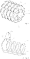
- the in Figure 1 The hob shown has a cylindrical base body 10, on the circumference of which a plurality of cutting teeth 12 are arranged along a helical shape.
- the cylindrical base body 10 has an axial bore 14 for clamping in a machine tool.
- a closed cooling channel system is formed in the hob, which in Figure 2 for illustration without the base body and using a cutting tooth of the in Figure 1 shown hob is shown.
- the closed cooling duct system has a supply duct 16 running helically in the base body 10 around the axial bore 14, one end 18 of which is connected to a coolant supply opening 20 in the base body 10 and the other end 22 of which is connected to a coolant discharge opening 24 in the base body 10.
- coolant for example a coolant, such as a water-oil mixture
- a coolant such as a water-oil mixture
- the helical shape of the supply channel 16 is adapted to the helical shape of the cutting tooth arrangement.
- FIG 2 this is shown by way of illustration for a cutting tooth 12.
- the reference numeral 26 is in Figure 2 the section of the cooling duct branching off from the supply duct 16, which enters the cutting tooth 12.
- the section 28 of the cooling channel which, coming from the cutting tooth 12, flows back into the supply channel 16 can be seen at reference number 28.
- such cooling channels 26, 28 are for each of the cutting teeth 12 of the in Figure 1 shown hob.
- FIG 3 An exemplary embodiment of a course of the cooling channels branching off from the supply channel 16 within the cutting tooth 12 is shown.
- the cooling channels each have a cooling section 30 which runs spirally within the cutting tooth 12.
- FIGS Figures 4 to 7 A further exemplary embodiment for forming the cooling channels within the cutting teeth 12 is shown in FIGS Figures 4 to 7 shown.
- a cooling reservoir 32 which is connected to the respective cooling channel and enlarged in cross-section with respect to the respective cooling channel, is formed within the cutting teeth 12.
- the section 26 of the respective cooling channel coming from the supply channel 16 enters the cooling reservoir 32 from one side.
- the second section 28 of the respective cooling channel leads away from an opposite side of the cooling reservoir 32.
- the cooling reservoirs 32 extend in two degrees of freedom, namely in the direction of FIG Figure 4 shown tooth width B and in the direction of in Figure 3 shown tooth thickness D of the cutting teeth 12. In this way it is ensured that optimal cooling takes place on the outer surfaces of the cutting teeth 12.
- the cooling reservoirs 32 have a three-dimensional shape which favors the cooling effect.
- the cooling reservoir 32 thus forms a funnel shape, which ensures that the required cooling takes place reliably in the vicinity of the outer surfaces of the respective cutting tooth 12.
- the distance S of the cooling reservoirs 32 to the rake face and the distance K of the cooling reservoirs 32 to the outside of the tooth tip are selected so that the hob can be reprocessed when worn by regrinding the cutting teeth and at the same time cooling is sufficiently effective even for new tools that have not yet been reprocessed.
- H is in Fig. 6 the profile height of the respective cutting tooth is shown.
- D is in Fig. 6 the tooth thickness shown.
- K K > 1 + F 1 ⁇ H , where F1 is a factor between 0.05 mm and 0.2 mm. F1 is preferably 0.1 mm.
- S has proven to be particularly suitable if: S > 1.5 + F 2nd ⁇ D , where F2 is a factor between 0.05 mm and 0.4 mm. F2 is preferably 0.2 mm.
- Fig. 8 is shown a hob according to the invention.
- FIGS Figures 1 to 7 This embodiment differs from that in FIGS Figures 1 to 7
- the exemplary embodiments shown are merely characterized in that an open cooling channel system is provided in addition to the closed cooling channel system.
- the in Fig. 8 shown hob can be designed as in the Figures 1 to 7 shown.
- the open cooling channel system has a coolant supply opening 34 arranged on the end face of the base body 10 and a plurality of outlet openings 36, 38 in the region of the cutting teeth 12.
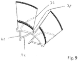
- the course of the cooling channels in the cutting teeth 12 is shown in FIG Fig. 9 recognizable more precisely. It can be seen from a supply channel (not shown in detail) that runs within the base body 10 and leads to the outlet openings 36, 38 and leads to the cooling openings 40, 42 axial bore 14 run.
Landscapes
- Engineering & Computer Science (AREA)
- Mechanical Engineering (AREA)
- Gear Processing (AREA)
Description
- Die Erfindung betrifft einen Wälzfräser mit einem zylindrischen Grundkörper, an dessen Umfang eine Mehrzahl von Schneidzähnen ausgebildet ist. Die Erfindung betrifft außerdem ein Verfahren zum Betreiben eines solchen Wälzfräsers.
- Wälzfräser besitzen einen meist zylindrischen Grundkörper, an dessen Umfang eine Vielzahl von Schneidzähnen ausgebildet ist. Die Schneidzähne dienen zum zerspanenden Bearbeiten eines Werkstücks. Ein Wälzfräser ist beispielsweise bekannt aus
DE 44 45 911 C1 . Bei diesem Wälzfräser ist ein offenes Kühlkanalsystem vorgesehen, durch welches ein Kühlmittel durch den Wälzfräser geleitet wird und durch Öffnungen am Umfang des Grundkörpers zwischen in Umfangsrichtung beabstandeten Schneideinsätzen austritt. Das Kühlkanalsystem wird durch Bohren eingebracht. - Die Geometrie des Kühlkanalsystems ist nur in engen Grenzen variabel, da die Richtung der gebohrten Kühlkanäle nicht ohne weiteres geändert werden kann. Auch ist die durch ein offenes Kühlkanalsystem der beschriebenen Art erreichte Kühlwirkung nicht immer ausreichend.
- Aus
US 2013/0302098 A1 ist ein Wälzfräser bekannt, der aus mehreren scheibenförmigen Segmenten aufgebaut ist. Jedes Segment weist ein zentrales Durchgangsloch auf, welches auf der Drehachse des Wälzfräsers liegt, wobei die Durchgangslöcher gemeinsam eine Leitung für ein Kühlmittel bilden. Diese Kühlleitung kann geschlossen sein.US 2013/0302098 A1 zeigt den Oberbegriff des Anspruchs 1. - Aus
US 2 511 964 A ist ein Wälzfräser bekannt mit einem axialen Einspannabschnitt zum Einspannen in eine Werkzeugmaschine. - Aus
CN 204108438 U undCN 202239838 U sind Werkzeuge mit wendelförmigen Kühlkanälen bekannt. - Aus
DE 10 2004 032 093 A1 ist ein Bauteil bekannt, das in einem selektiven Lasersintervorgang (SLS) hergestellt worden ist. - Aus
DE 20 2013 101 070 U1 ist schließlich ein Werkzeug für eine Werkzeugmaschine bekannt, das einen vollständig in seinem Inneren verlaufenden Kühlmittelkanal aufweist, der sich zwischen einem Kühlmitteleinlass und einem Kühlmittelauslass erstreckt, wobei der Kühlmitteleinlass und der Kühlmittelauslass an ein Kühlmittelkreislauf der Werkzeugmaschiene anschließbar sind. - Ausgehend von dem erläuterten Stand der Technik liegt der Erfindung die Aufgabe zugrunde, einen Wälzfräser sowie Verfahren der eingangs genannten Art bereitzustellen, wobei ein Kühlkanalsystem mit optimierter und flexibel gestaltbarer Kühlwirkung vorgesehen ist.
- Die Erfindung löst die Aufgabe durch die unabhängigen Ansprüche 1 und 12.
- Vorteilhafte Ausgestaltungen finden sich in den abhängigen Ansprüchen, der Beschreibung und den Figuren.
- Für einen Wälzfräser der eingangs genannten Art löst die Erfindung die Aufgabe dadurch, dass in dem Grundkörper ein geschlossenes Kühlkanalsystem für ein Kühlmittel ausgebildet ist, mit einer an einer Stirnseite des Grundkörpers angeordneten Kühlmittelzuführöffnung und einer ebenfalls an einer Stirnseite des Grundkörpers angeordneten Kühlmittelabführöffnung, wobei sich das Kühlkanalsystem über die axiale Ausdehnung des Grundkörpers erstreckt, wobei in dem Grundkörper zusätzlich ein von dem geschlossenen Kühlkanalsystem getrenntes offenes Kühlkanalsystem für ein Kühlmittel ausgebildet ist mit einer an einer Stirnseite des Grundkörpers angeordneten Kühlmittelzuführöffnung und einer Mehrzahl von Austrittsöffnungen im Bereich der Schneidzähne.
- In an sich bekannter Weise besitzt der erfindungsgemäße Wälzfräser einen zylindrischen Grundkörper, an dessen Umfang eine Mehrzahl von insbesondere einstückig mit dem Grundkörper ausgebildeten Schneidzähnen ausgebildet ist. Die Schneidzähne können beispielsweise schneckenförmig über den Umfang des Grundkörpers verteilt angeordnet sein. An den Schneidzähnen können wechselbare Schneidplatten befestigt sein. Erfindungsgemäß ist in dem Wälzfräser ein geschlossenes Kühlkanalsystem vorgesehen. Dieses Kühlkanalsystem besitzt bis auf die Kühlmittelzuführöffnung und die Kühlmittelabführöffnung also keine weiteren Öffnungen, insbesondere keine Austrittsöffnungen am Umfang des Grundkörpers im Bereich der Schneidzähne. Die Kühlmittelzuführöffnung und die Kühlmittelabführöffnung können insbesondere an derselben Stirnseite des Grundkörpers angeordnet sein. Sofern in diesem Zusammenhang auf eine Richtung des Kühlkanalsystems Bezug genommen wird, bezieht sich dies auf die Fließrichtung des Kühlmittels in dem Kühlkanalsystem. Vorgegeben ist diese durch die Kühlmittelzuführöffnung, über die das Kühlmittel in das Kühlkanalsystem eingeleitet wird und die Kühlmittelabführöffnung, über die das Kühlmittel aus dem Kühlkanalsystem abgeführt wird.
- Durch das erfindungsgemäße geschlossene Kühlkanalsystem wird eine optimale Kühlung gewährleistet. Durch eine individuell angepasste Geometrie der Kanäle des Kühlkanalsystems kann sichergestellt werden, dass alle zu kühlenden Bereiche des Wälzfräsers jederzeit ausreichend temperiert werden. Durch eine zuverlässige Temperierung des Wälzfräsers können hohe Bearbeitungsgeschwindigkeiten gewährleistet werden. Außerdem kann der Prozess an der Zerspanstelle trocken gehalten werden, was in manchen Anwendungen wünschenswert ist.
- Die Kanäle des geschlossenen Kühlkanalsystems können beispielsweise einen kreisförmigen Querschnitt besitzen. Zwingend ist dies jedoch nicht. Bei dem durch das Kühlkanalsystem zu leitenden Kühlmittel kann es sich insbesondere um eine Kühlflüssigkeit handeln, beispielsweise Öl und/oder Wasser.
- Der Grundkörper kann einen axialen Einspannabschnitt zum Einspannen des Wälzfräsers in einer Werkzeugmaschine umfassen, wobei das Kühlkanalsystem einen in dem Grundkörper wendelförmig um den axialen Einspannabschnitt verlaufenden Versorgungskanal umfasst, der mit der Kühlmittelzufuhröffnung und der Kühlmittelabführöffnung verbunden ist. Weiterhin können die Schneidzähne entlang einer Wendelform am Umfang des Grundkörpers angeordnet sein und die Wendelform des Versorgungskanals kann der Wendelform der Schneidzahnanordnung entsprechen. Der Einspannabschnitt kann zum Beispiel eine axiale Bohrung zur Aufnahme einer Antriebswelle der Werkzeugmaschine sein. Es kann sich aber auch um einen axialen Fortsatz handeln, der entsprechend in einer Aufnahme der Werkzeugmaschine aufgenommen wird. Oftmals sind die Schneidzähne bei Wälzfräsern schneckenförmig entlang einer Wendel verteilt am Umfang des Grundkörpers angeordnet. Sofern gemäß der o.g. Ausgestaltung die Wendelform des Versorgungskanals der Wendelform der Schneidzahnanordnung entspricht, erstreckt sich der Versorgungskanal unterhalb jedes Schneidzahns, wodurch die Kühlwirkung optimiert wird.
- Von dem Versorgungskanal kann eine Mehrzahl von Kühlkanälen abzweigen, wobei die Kühlkanäle jeweils einen Schneidzahn durchlaufen und anschließend wieder in den Versorgungskanal münden. Es sind dabei insbesondere so viele Kühlkanäle wie Schneidzähne vorgesehen. Jeder Kühlkanal ist einem Schneidzahn zugeordnet, den er durchläuft. Die Abzweigung und Wiedereinmündung in den Versorgungskanal kann innerhalb des Grundkörpers insbesondere jeweils unter dem zugeordneten Schneidzahn vorgesehen sein. Zwischen ihrer Abzweigung aus dem Versorgungskanal und ihrer Wiedereinmündung in den Versorgungskanal sind die Kühlkanäle zumindest abschnittsweise innerhalb des jeweiligen Schneidzahns angeordnet und sorgen dort für eine gezielte Temperierung jedes Schneidzahns.
- Die Kühlkanäle können jeweils einen innerhalb des jeweiligen Schneidzahns spiralförmig verlaufenden Kühlabschnitt aufweisen. Auf diese Weise wird eine gleichmäßige und großflächige Kühlung der Schneidzähne erreicht.
- Nach einer weiteren Ausgestaltung kann vorgesehen sein, dass innerhalb der Schneidzähne ein mit dem jeweiligen Kühlkanal verbundenes und gegenüber dem jeweiligen Kühlkanal im Querschnitt vergrößertes Kühlreservoir ausgebildet ist. Durch diese Ausgestaltung kann die Kühlwirkung weiter verbessert werden. Die Kühlreservoirs werden durch taschenförmige Hohlräume innerhalb der Schneidzähne gebildet, in die jeweils ein erster von dem Versorgungskanal kommender Abschnitt der Kühlkanäle beispielsweise von einer Seite mündet und aus denen jeweils ein zweiter, wieder zurück zu dem Versorgungskanal führender Abschnitt der Kühlkanäle beispielsweise von einer gegenüberliegenden Seite abgeht. Die Kühlreservoirs sind im Querschnitt im Vergleich zu den Kühlkanälen erheblich vergrößert, insbesondere um ein Mehrfaches. Sie erstrecken sich insbesondere in zwei Richtungen, nämlich sowohl in Richtung der Schneidzahnbreite als auch der Schneidzahndicke. Dadurch wird gewährleistet, dass eine optimale Kühlung an den Außenflächen des Schneidzahns erfolgt. Vorteilhaft sind die Kühlreservoirs so gestaltet, dass sowohl die Stabilität des jeweiligen Schneidzahns als auch die optimale Kühlung der Außenflächen gewährleistet ist. Die Kühlreservoirs füllen sich im Betrieb mit Kühlmittel, welches aber gleichwohl über die Kühlkanäle ständig ausgetauscht wird, so dass die insoweit verstärkte Kühlwirkung im Wesentlichen konstant ist.
- Eine weitere Verbesserung der Kühlwirkung lässt sich erreichen, wenn die Kühlreservoirs sich gemäß einer weiteren Ausgestaltung jeweils unterhalb des größten Teils der Zahnkopfoberfläche der Schneidzähne erstrecken.
- Die Querschnittsform der Kühlreservoirs kann nach einer weiteren Ausgestaltung jeweils an die Querschnittsform der Schneidzähne im Bereich des Zahnkopfes angepasst sein. Durch diese individuelle Anpassung der Kühlreservoirs an die Schneidzahngeometrie wird eine weitere Verbesserung der Kühlwirkung erreicht.
- Der Abstand S der Kühlreservoirs zur Spanfläche und der Abstand K der Kühlreservoirs zur Außenseite des Zahnkopfs können dabei jeweils so gewählt werden, dass ein Aufbereiten des Wälzfräsers bei Verschleiß durch Nachschleifen der Schneidzähne ermöglicht wird und gleichzeitig eine Kühlung auch bei neuen Werkzeugen, die noch keiner Aufbereitung unterzogen wurden, ausreichend wirksam ist.
- Als besonders geeignet in dieser Hinsicht hat sich herausgestellt wenn für K gilt:

- Für S hat sich in dieser Hinsicht als besonders geeignet herausgestellt, wenn gilt:

- Erfindungsgemäß ist vorgesehen, dass in dem Grundkörper zusätzlich ein von dem geschlossenen Kühlkanalsystem getrenntes offenes Kühlkanalsystem für ein Kühlmittel ausgebildet ist mit einer an einer Stirnseite des Grundkörpers angeordneten Kühlmittelzuführöffnung und einer Mehrzahl von Austrittsöffnungen im Bereich der Schneidzähne. Ein zusätzliches, offenes Kühlkanalsystem kann neben einer weiteren Kühlwirkung, insbesondere der direkten Kühlung der Außenflächen der Schneidzähne, zum schnellen Abtransport der im Betrieb erzeugten Späne genutzt werden. Bei Zerspanungswerkzeugen ist der Spanabtransport bedeutend, um die Standzeit der Werkzeuge wirtschaftlich zu halten. Es ist erforderlich, Späne so schnell wie möglich von der Wirkstelle zu entfernen, um ein Anhaften am Werkzeug zu vermeiden. Bei Wälzfräsern ist dies besonders bedeutend, da es sich um ein Verfahren mit einem besonders großen Zeitspanvolumen handelt. Das zusätzlich vorgesehene offene Kühlkanalsystem dient also insbesondere zum schnellen und gezielten Abführen von im Betrieb erzeugten Spänen. Dazu kann das offene Kühlkanalsystem zum Beispiel einen mit der Kühlmittelzuführöffnung verbundenen Kühlmittelversorgungskanal umfassen, von dem dann eine Mehrzahl von zu den Austrittsöffnungen führenden Kühlmittelverteilkanälen abgeht. Die Austrittsöffnungen können zum Beispiel so angeordnet sein, dass die unter hohem Druck austretende Kühlflüssigkeit auf die Spanflächen der Schneidzähne trifft. Auch die Kanäle des geschlossenen Kühlkanalsystems können einen kreisförmigen Querschnitt besitzen, zwingend ist dies wiederum nicht.
- Nach einer weiteren Ausgestaltung kann der erfindungsgemäße Wälzfräser in einem additiven Verfahren bzw. einem 3D-Druckverfahren hergestellt worden sein. Durch additive Verfahren lassen sich die erfindungsgemäßen Kühlkanalsysteme besonders flexibel und einfach herstellen. Insbesondere lassen sich flexible Geometrien erzeugen, die durch das herkömmliche Erzeugen von Kühlkanälen durch Bohren nicht möglich sind. Dies betrifft insbesondere die oben erläuterten Geometrien mit wendelfömigem Versorgungskanal, von dem Versorgungskanal abzweigenden Kühlkanälen und innerhalb der Schneidzähne ausgebildeten Kühlmittelreservoirs. Nach dem additiven Verfahren kann noch eine Fertigbearbeitung des Wälzfräsers, insbesondere durch Schleifen, erfolgen. Auch kann insbesondere nach einem additiven Verfahren, und gegebenenfalls nach einer Fertigbearbeitung beispielsweise durch Schleifen, noch eine Beschichtung des Wälzfräsers mit einer Hartstoffschicht erfolgen, vorzugsweise in einem CVD-Verfahren oder einem PVD-Verfahren.
- Der erfindungsgemäße Wälzfräser kann aus einem Schnellarbeitsstahlwerkstoff, insbesondere einer intermetallischen Legierung, oder aus einem Hartmetallwerkstoff oder aus einem Keramikwerkstoff bestehen. Es handelt sich hierbei um besonders verschleißfeste Materialien, die gut in additiven Verfahren verarbeitet werden können.
- Die Erfindung betrifft auch ein Verfahren zum Herstellen eines erfindungsgemäßen Wälzfräsers, bei dem in einem additiven Verfahren in einer Form Material schichtweise aufgebracht und durch selektives Aufschmelzen und/oder Sintern des aufgebrachten Materials zumindest der Grundkörper mit den Schneidzähnen und dem geschlossenen Kühlkanalsystem und gegebenenfalls auch dem offenen Kühlkanalsystem, aufgebaut wird.
- Das insbesondere pulverförmige Material wird für den 3D-Druck schichtweise in eine Form ausgebracht. Bei dem Material kann es sich beispielsweise um einen Metallwerkstoff oder einen Keramikwerkstoff handeln. Das selektive Aufschmelzen oder Sintern des Materials zum Bilden der gewünschten dreidimensionalen Form kann ein selektives Laserschmelzen oder selektives Lasersintern sein. Es erfolgt somit ein schichtweiser Aufbau des Wälzfräsers, insbesondere seines Grundkörpers und der Schneidzähne sowie der Kühlkanäle. Wie erläutert, kann nach dem additiven Verfahren kann noch eine Fertigbearbeitung des Wälzfräsers, insbesondere durch Schleifen, erfolgen. Wie ebenfalls erläutert, kann nach dem additiven Verfahren, und gegebenenfalls nach einer Fertigbearbeitung beispielsweise durch Schleifen, auch noch eine Beschichtung des Wälzfräsers mit einer Hartstoffschicht erfolgen, vorzugsweise in einem CVD-Verfahren oder einem PVD-Verfahren.
- Die Erfindung betrifft außerdem ein Verfahren zum Betreiben eines erfindungsgemäßen Wälzfräsers, mit geschlossenem Kühlkanalsystem und offenem Kühlkanalsystem, wobei im Betrieb durch das geschlossene Kühlkanalsystem ein anderes Kühlmittel geleitet wird als durch das offene Kühlkanalsystem. Beispielsweise kann es sich bei dem durch das geschlossene Kühlkanalsystem geführten Kühlmittel um eine Kühlflüssigkeit mit hoher Kühlwirkung handeln, zum Beispiel ein Öl oder ein Wasser-Öl-Gemisch. Bei dem durch das offene Kühlkanalsystem geführten Kühlmittel kann es sich um eine Kühlflüssigkeit für einen maximalen Spanabtransport handeln, zum Beispiel Wasser. Auch kann das durch das offene Kühlkanalsystem geführte Kühlmittel unter höherem Druck durch das offene Kühlkanalsystem geführt werden als das durch das geschlossene Kühlkanalsystem geführte Kühlmittel. Auf diese Weise wird der Spanabtransport weiter befördert.
- In Bezug auf den erfindungsgemäßen Wälzfräser kann die Kühlmittelzuführöffnung des geschlossenen Kühlkanalsystems mit einer anderen Kühlmittelversorgung, beispielsweise einer Versorgung für Kühlflüssigkeit mit hoher Kühlwirkung, zum Beispiel Öl oder ein Wasser-Öl-Gemisch, oder einem anderen Kühlfluid, wie gekühlte Luft, verbunden sein als die Kühlmittelzuführöffnung des offenen Kühlkanalsystems, welche beispielsweise mit einer Versorgung für Kühlflüssigkeit für maximalen Spanabtransport, zum Beispiel Wasser, verbunden sein kann.
- Ausführungsbeispiele der Erfindung werden nachfolgend anhand von Figuren näher erläutert. Es zeigen schematisch:
- Fig. 1
- einen Wälzfräser in einer perspektivischen Ansicht,
- Fig. 2
- eine Visualisierung des bei dem Wälzfräser aus
Fig. 1 vorgesehenen Kühlkanalsystems anhand eines Schneidzahns des inFig. 1 gezeigten Wälzfräsers, - Fig. 3
- eine Schnittansicht durch einen Schneidzahn des in
Fig. 1 gezeigten Wälzfräsers, - Fig. 4
- eine teiltransparente perspektivische Ansicht eines Schneidzahns des in
Fig. 1 gezeigten Wälzfräsers nach einem weiteren Ausführungsbeispiel, - Fig. 5
- eine Ansicht von vorn auf den in
Fig. 4 gezeigten Schneidzahns, - Fig. 6
- eine Schnittansicht entlang der Linie 6-6 in
Fig. 5 , - Fig. 7
- eine Schnittansicht entlang der Linie 7-7 in
Fig. 5 , - Fig. 8
- einen erfindungsgemäßen Wälzfräser in einer perspektivischen Ansicht, und
- Fig. 9
- eine teiltransparente Seitenansicht zweier Schneidzähne des in
Fig. 8 gezeigten Wälzfräsers. - Soweit nichts anderes angegeben ist, bezeichnen in den Figuren gleiche Bezugszeichen gleiche Gegenstände.
- Der in
Figur 1 gezeigte Wälzfräser besitzt einen zylindrischen Grundkörper 10, an dessen Umfang eine Mehrzahl von Schneidzähnen 12 entlang einer Wendelform angeordnet ist. Der zylindrische Grundkörper 10 besitzt eine axiale Bohrung 14 zum Einspannen in eine Werkzeugmaschine. In dem Wälzfräser ist ein geschlossenes Kühlkanalsystem ausgebildet, welches inFigur 2 zur Veranschaulichung ohne den Grundkörper und anhand eines Schneidzahns des inFigur 1 gezeigten Wälzfräsers dargestellt ist. Das geschlossene Kühlkanalsystem besitzt eine in dem Grundkörper 10 wendelförmig um die axiale Bohrung 14 verlaufenden Versorgungskanal 16, dessen eines Ende 18 mit einer Kühlmittelzuführöffnung 20 in dem Grundköroper 10 verbunden ist und dessen anderes Ende 22 mit einer Kühlmittelabführöffnung 24 in dem Grundkörper 10 verbunden ist. Über die Kühlmittelzuführöffnung 20 wird im Betrieb Kühlmittel, beispielsweise eine Kühlflüssigkeit, wie ein Wasser-Öl-Gemisch, in den Versorgungskanal 16 eingeleitet. Nach Durchlaufen des geschlossenen Kühlkanalsystems tritt das Kühlmittel wieder über die Kühlmittelabführöffnung 24 aus. Die Wendelform des Versorgungskanals 16 ist an die Wendelform der Schneidzahnanordnung angepasst. - Von dem Versorgungskanal 16 zweigt eine Mehrzahl von Kühlkanälen ab, die jeweils einen der Schneidzähne 12 durchlaufen und anschließend wieder in den Versorgungskanal 16 münden. In
Figur 2 ist dies zur Veranschaulichung für einen Schneidzahn 12 dargestellt. Bei dem Bezugszeichen 26 ist inFigur 2 der von dem Versorgungskanal 16 abzweigende Abschnitt des Kühlkanals zu erkennen, der in den Schneidzahn 12 eintritt. Bei dem Bezugszeichen 28 ist der Abschnitt des Kühlkanals zu erkennen, der von dem Schneidzahn 12 kommend wieder in den Versorgungskanal 16 mündet. Wie erwähnt, sind solche Kühlkanäle 26, 28 für jeden der Schneidzähne 12 des inFigur 1 gezeigten Wälzfräsers vorgesehen. - In
Figur 3 ist ein Ausführungsbeispiel eines Verlaufs der von dem Versorgungskanal 16 abzweigenden Kühlkanäle innerhalb des Schneidzahns 12 gezeigt. In diesem Beispiel weisen die Kühlkanäle jeweils einen innerhalb des Schneidzahns 12 spiralförmig verlaufenden Kühlabschnitt 30 auf. - Ein weiteres Ausführungsbeispiel für eine Ausbildung der Kühlkanäle innerhalb der Schneidzähne 12 ist in den
Figuren 4 bis 7 gezeigt. Bei diesem Ausführungsbeispiel ist innerhalb der Schneidzähne 12 jeweils ein mit dem jeweiligen Kühlkanal verbundenes und gegenüber dem jeweiligen Kühlkanal im Querschnitt vergrößertes Kühlreservoir 32 ausgebildet. Wie insbesondere inFigur 6 zu erkennen, tritt der von dem Versorgungskanal 16 kommende Abschnitt 26 des jeweiligen Kühlkanals von einer Seite in das Kühlreservoir 32 ein. Der zweite Abschnitt 28 des jeweiligen Kühlkanals führt von einer gegenüberliegenden Seite des Kühlreservoirs 32 weg. - Wie sich insbesondere aus einem Vergleich der
Figuren 6 und7 ergibt, erstrecken sich die Kühlreservoirs 32 in zwei Freiheitsgrade, nämlich in Richtung der inFigur 4 dargestellten Zahnbreite B und in Richtung der inFigur 3 gezeigten Zahndicke D der Schneidzähne 12. Auf diese Weise wird gewährleistet, dass eine optimale Kühlung an den Außenflächen der Schneidzähne 12 erfolgt. Außerdem ist insbesondere in den Schnittdarstellungen derFiguren 6 und7 zu erkennen, dass die Kühlreservoirs 32 eine die Kühlwirkung begünstigende dreidimensionale Form aufweist. So bildet das Kühlreservoir 32 eine Trichterform aus, die sicherstellt, dass die erforderliche Kühlung in der Nähe der Außenflächen des jeweiligen Schneidzahns 12 zuverlässig erfolgt. - Der Abstand S der Kühlreservoirs 32 zur Spanfläche und der Abstand K der Kühlreservoirs 32 zur Außenseite des Zahnkopfs (s.
Fig. 6 ) sind dabei jeweils so gewählt, dass ein Aufbereiten des Wälzfräsers bei Verschleiß durch Nachschleifen der Schneidzähne ermöglicht wird und gleichzeitig eine Kühlung auch bei neuen Werkzeugen, die noch keiner Aufbereitung unterzogen wurden, ausreichend wirksam ist. Bei H ist inFig. 6 die Profilhöhe des jeweiligen Schneidzahns eingezeichnet. Bei D ist inFig. 6 die Zahndicke gezeigt. - Als besonders geeignet hat es sich herausgestellt wenn für K gilt:

- Für S hat sich als besonders geeignet herausgestellt, wenn gilt:

- In
Fig. 8 ist ein Wälzfräser nach der Erfindung gezeigt. - Dieses Ausführungsbeispiel unterscheidet sich von den in den
Figuren 1 bis 7 gezeigten Ausführungsbeispielen lediglich dadurch, dass zusätzlich zu dem geschlossenen Kühlkanalsystem ein offenes Kühlkanalsystem vorgesehen ist. Abgesehen von diesem Unterschied kann der inFig. 8 gezeigte Wälzfräser ausgebildet sein, wie in denFiguren 1 bis 7 gezeigt. - Das offene Kühlkanalsystem besitzt eine an der Stirnseite des Grundkörpers 10 angeordnete Kühlmittelzuführöffnung 34 und eine Mehrzahl von Austrittsöffnungen 36, 38 im Bereich der Schneidzähne 12. Der Verlauf der Kühlkanäle in den Schneidzähnen 12 ist in
Fig. 9 genauer zu erkennen. Zu erkennen sind von einem nicht näher dargestellten, innerhalb des Grundkörpers 10 verlaufenden Versorgungskanal abgehende, zu den Austrittsöffnungen 36, 38 führende Kühlkanäle 40, 42. Der mit der Kühlmittelzuführöffnung 34 verbundene Versorgungskanal kann ähnlich wie der Versorgungskanal 16 des oben erläuterten geschlossenen Kühlkanalsystems wendelförmig um die axiale Bohrung 14 verlaufen.
Claims (12)
- Wälzfräser mit einem zylindrischen Grundkörper (10), an dessen Umfang eine Mehrzahl von Schneidzähnen (12) ausgebildet ist, wobei in dem Grundkörper (10) ein geschlossenes Kühlkanalsystem für ein Kühlmittel ausgebildet ist, mit einer an einer Stirnseite des Grundkörpers (10) angeordneten Kühlmittelzuführöffnung (20) und einer ebenfalls an einer Stirnseite des Grundkörpers (10) angeordneten Kühlmittelabführöffnung (24), wobei sich das Kühlkanalsystem über die axiale Ausdehnung des Grundkörpers (10) erstreckt, dadurch gekennzeichnet, dass in dem Grundkörper (10) zusätzlich ein von dem geschlossenen Kühlkanalsystem getrenntes offenes Kühlkanalsystem für ein Kühlmittel ausgebildet ist mit einer an einer Stirnseite des Grundkörpers (10) angeordneten Kühlmittelzuführöffnung (34) und einer Mehrzahl von Austrittsöffnungen (36, 38) im Bereich der Schneidzähne (12).
- Wälzfräser nach Anspruch 1, dadurch gekennzeichnet, dass der Grundkörper (10) einen axialen Einspannabschnitt zum Einspannen des Wälzfräsers in einer Werkzeugmaschine umfasst, wobei das Kühlkanalsystem einen in dem Grundkörper (10) wendelförmig um den axialen Einspannabschnitt verlaufenden Versorgungskanal (16) umfasst, der mit der Kühlmittelzuführöffnung (20) und der Kühlmittelabführöffnung (24) verbunden ist.
- Wälzfräser nach Anspruch 2, dadurch gekennzeichnet, dass die Schneidzähne (12) entlang einer Wendelform am Umfang des Grundkörpers (10) angeordnet sind, und dass die Wendelform des Versorgungskanals (16) der Wendelform der Schneidzahnanordnung entspricht.
- Wälzfräser nach einem der Ansprüche 2 oder 3, dadurch gekennzeichnet, dass von dem Versorgungskanal (16) eine Mehrzahl von Kühlkanälen (26, 28) abzweigt, wobei die Kühlkanäle (26, 28) jeweils einen Schneidzahn durchlaufen und anschließend wieder in den Versorgungskanal (16) münden.
- Wälzfräser nach Anspruch 4, dadurch gekennzeichnet, dass die Kühlkanäle (26, 28) jeweils einen innerhalb des jeweiligen Schneidzahns spiralförmig verlaufenden Kühlabschnitt (30) aufweisen.
- Wälzfräser nach einem der Ansprüche 4 oder 5, dadurch gekennzeichnet, dass innerhalb der Schneidzähne (12) ein mit dem jeweiligen Kühlkanal (26, 28) verbundenes und gegenüber dem jeweiligen Kühlkanal (26, 28) im Querschnitt vergrößertes Kühlreservoir (32) ausgebildet ist.
- Wälzfräser nach Anspruch 6, dadurch gekennzeichnet, dass die Kühlreservoirs (32) sich jeweils unterhalb des größten Teils der Zahnkopfoberfläche der Schneidzähne (12) erstrecken.
- Wälzfräser nach einem der Ansprüche 6 oder 7, dadurch gekennzeichnet, dass die Querschnittsform der Kühlreservoirs (32) jeweils an die Querschnittsform der Schneidzähne (12) im Bereich des Zahnkopfes angepasst ist.
- Wälzfräser nach einem der vorhergehenden Ansprüche, dadurch gekennzeichnet, dass er in einem additiven Verfahren hergestellt worden ist.
- Wälzfräser nach einem der vorhergehenden Ansprüche, dadurch gekennzeichnet, dass er aus einem Schnellarbeitsstahlwerkstoff, insbesondere einer intermetallischen Legierung, oder aus einem Hartmetallwerkstoff oder aus einem Keramikwerkstoff besteht.
- Wälzfräser nach einem der vorhergehenden Ansprüche, dadurch gekennzeichnet, dass er mit einer Hartstoffschicht beschichtet ist, vorzugsweise hergestellt in einem CVD-Verfahren oder einem PVD-Verfahren.
- Verfahren zum Betreiben eines Wälzfräsers nach einem der vorhergehenden Ansprüche, dadurch gekennzeichnet, dass im Betrieb durch das geschlossene Kühlkanalsystem ein anderes Kühlmittel geleitet wird als durch das offene Kühlkanalsystem.
Priority Applications (1)
| Application Number | Priority Date | Filing Date | Title |
|---|---|---|---|
| EP15198488.7A EP3178593B1 (de) | 2015-12-08 | 2015-12-08 | Wälzfräser und verfahren zum herstellen und betreiben eines wälzfräsers |
Applications Claiming Priority (1)
| Application Number | Priority Date | Filing Date | Title |
|---|---|---|---|
| EP15198488.7A EP3178593B1 (de) | 2015-12-08 | 2015-12-08 | Wälzfräser und verfahren zum herstellen und betreiben eines wälzfräsers |
Publications (2)
| Publication Number | Publication Date |
|---|---|
| EP3178593A1 EP3178593A1 (de) | 2017-06-14 |
| EP3178593B1 true EP3178593B1 (de) | 2020-03-25 |
Family
ID=54838221
Family Applications (1)
| Application Number | Title | Priority Date | Filing Date |
|---|---|---|---|
| EP15198488.7A Active EP3178593B1 (de) | 2015-12-08 | 2015-12-08 | Wälzfräser und verfahren zum herstellen und betreiben eines wälzfräsers |
Country Status (1)
| Country | Link |
|---|---|
| EP (1) | EP3178593B1 (de) |
Families Citing this family (2)
| Publication number | Priority date | Publication date | Assignee | Title |
|---|---|---|---|---|
| JP6362802B1 (ja) * | 2018-01-23 | 2018-07-25 | 株式会社松浦機械製作所 | 切削工具 |
| CN112548231B (zh) * | 2020-12-01 | 2022-04-29 | 南京迈森智能装备有限公司 | 一种防止切屑残留的自冷式滚刀 |
Family Cites Families (7)
| Publication number | Priority date | Publication date | Assignee | Title |
|---|---|---|---|---|
| US2511964A (en) * | 1946-10-17 | 1950-06-20 | Francis H Boor | Hob |
| DE4445911C1 (de) | 1994-12-22 | 1995-12-21 | Fette Wilhelm Gmbh | Kühlmittel-Zuführeinrichtung in einem Wälzfräser |
| DE102004032093B4 (de) * | 2004-07-01 | 2007-05-16 | Cl Schutzrechtsverwaltungs Gmbh | Durch einen selektiven Lasersintervorgang (SLS) hergestelltes Bauteil |
| CN202239838U (zh) * | 2011-10-13 | 2012-05-30 | 东阳市速博数控刀具有限公司 | 一种硬质合金铣刀 |
| SE536487C2 (sv) * | 2012-05-09 | 2013-12-17 | Sandvik Intellectual Property | Fräsverktyg för hobbning |
| DE202013101070U1 (de) * | 2013-03-12 | 2013-03-18 | Karl Keppler Maschinenbau Gmbh | Werkzeug für eine Werkzeugmaschine |
| CN204108438U (zh) * | 2014-08-08 | 2015-01-21 | 江苏美杰磨具科技有限公司 | 一种用于玻璃磨削的内冷式铣刀 |
-
2015
- 2015-12-08 EP EP15198488.7A patent/EP3178593B1/de active Active
Non-Patent Citations (1)
| Title |
|---|
| None * |
Also Published As
| Publication number | Publication date |
|---|---|
| EP3178593A1 (de) | 2017-06-14 |
Similar Documents
| Publication | Publication Date | Title |
|---|---|---|
| EP3186024B1 (de) | Scheibenfräser und herstellverfahren | |
| EP3285948B1 (de) | Drehwerkzeug mit sich verjüngendem kühlmittelkanal sowie versetzt angeordneten kühlmittelaustrittsleitungen und diesbezügliches herstellverfahren | |
| EP2962796B1 (de) | Reib-, fräs- oder bohrwerkzeug | |
| EP0937528B1 (de) | Reibwerkzeug und Verfahren zu dessen Herstellung | |
| DE102014207510B4 (de) | Zerspanungswerkzeug sowie Verfahren zum Herstellen eines Zerspanungswerkzeugs | |
| DE112009000578B4 (de) | Reibahle | |
| DE102010018339B4 (de) | Feinbearbeitungswerkzeug | |
| EP3791982A1 (de) | Fräswerkzeug mit kühlkanälen | |
| EP2313225B1 (de) | Spanabhebendes werkzeug mit minimalmengen-schmierung (mms) | |
| DE102011106416A1 (de) | Bohr-Reib-Werkzeug | |
| EP2364806A1 (de) | Trennwerkzeug | |
| DE102014108219A1 (de) | Rotationswerkzeug sowie Verfahren zur Herstellung eines Rotationswerkzeugs | |
| DE102012203088A1 (de) | Bohrkrone | |
| DE102017112696A1 (de) | Schneidwerkzeug | |
| DE102011082979A1 (de) | Reibwerkzeug und Verfahren zu dessen Herstellung | |
| EP3743234A1 (de) | Fräswerkzeug | |
| EP3768452B9 (de) | Tieflochbohrer mit mehreren spanformern und mulden in der spanfläche | |
| EP3630400B1 (de) | Einlippenbohrer und verfahren zum herstellen eines einlippenbohrers | |
| EP3178593A1 (de) | Wälzfräser und verfahren zum herstellen und betreiben eines wälzfräsers | |
| DE202016004094U1 (de) | Zerspanungswerkzeug | |
| EP0238477B1 (de) | Rotierbares spanabhebendes Werkzeug | |
| AT504385A1 (de) | Verfahren zur herstellung einer schnecke für einen extruder sowie schnecke | |
| EP3458213B1 (de) | Verfahren zur pulvermetallurgischen herstellung eines stabförmigen körpers | |
| CH705289A2 (de) | Metallrohr. | |
| DE102011076649B4 (de) | Schleifstift zum Schleifen einer Innenoberfläche eines Hohlraumes |
Legal Events
| Date | Code | Title | Description |
|---|---|---|---|
| PUAI | Public reference made under article 153(3) epc to a published international application that has entered the european phase |
Free format text: ORIGINAL CODE: 0009012 |
|
| STAA | Information on the status of an ep patent application or granted ep patent |
Free format text: STATUS: THE APPLICATION HAS BEEN PUBLISHED |
|
| AK | Designated contracting states |
Kind code of ref document: A1 Designated state(s): AL AT BE BG CH CY CZ DE DK EE ES FI FR GB GR HR HU IE IS IT LI LT LU LV MC MK MT NL NO PL PT RO RS SE SI SK SM TR |
|
| AX | Request for extension of the european patent |
Extension state: BA ME |
|
| STAA | Information on the status of an ep patent application or granted ep patent |
Free format text: STATUS: REQUEST FOR EXAMINATION WAS MADE |
|
| 17P | Request for examination filed |
Effective date: 20170823 |
|
| RBV | Designated contracting states (corrected) |
Designated state(s): AL AT BE BG CH CY CZ DE DK EE ES FI FR GB GR HR HU IE IS IT LI LT LU LV MC MK MT NL NO PL PT RO RS SE SI SK SM TR |
|
| RIC1 | Information provided on ipc code assigned before grant |
Ipc: B23F 17/00 20060101ALI20190904BHEP Ipc: B23F 21/16 20060101AFI20190904BHEP Ipc: B23C 5/28 20060101ALI20190904BHEP |
|
| GRAP | Despatch of communication of intention to grant a patent |
Free format text: ORIGINAL CODE: EPIDOSNIGR1 |
|
| STAA | Information on the status of an ep patent application or granted ep patent |
Free format text: STATUS: GRANT OF PATENT IS INTENDED |
|
| INTG | Intention to grant announced |
Effective date: 20191014 |
|
| GRAS | Grant fee paid |
Free format text: ORIGINAL CODE: EPIDOSNIGR3 |
|
| GRAA | (expected) grant |
Free format text: ORIGINAL CODE: 0009210 |
|
| STAA | Information on the status of an ep patent application or granted ep patent |
Free format text: STATUS: THE PATENT HAS BEEN GRANTED |
|
| AK | Designated contracting states |
Kind code of ref document: B1 Designated state(s): AL AT BE BG CH CY CZ DE DK EE ES FI FR GB GR HR HU IE IS IT LI LT LU LV MC MK MT NL NO PL PT RO RS SE SI SK SM TR |
|
| REG | Reference to a national code |
Ref country code: GB Ref legal event code: FG4D Free format text: NOT ENGLISH |
|
| REG | Reference to a national code |
Ref country code: DE Ref legal event code: R096 Ref document number: 502015012085 Country of ref document: DE |
|
| REG | Reference to a national code |
Ref country code: AT Ref legal event code: REF Ref document number: 1248011 Country of ref document: AT Kind code of ref document: T Effective date: 20200415 Ref country code: IE Ref legal event code: FG4D Free format text: LANGUAGE OF EP DOCUMENT: GERMAN |
|
| PG25 | Lapsed in a contracting state [announced via postgrant information from national office to epo] |
Ref country code: RS Free format text: LAPSE BECAUSE OF FAILURE TO SUBMIT A TRANSLATION OF THE DESCRIPTION OR TO PAY THE FEE WITHIN THE PRESCRIBED TIME-LIMIT Effective date: 20200325 Ref country code: NO Free format text: LAPSE BECAUSE OF FAILURE TO SUBMIT A TRANSLATION OF THE DESCRIPTION OR TO PAY THE FEE WITHIN THE PRESCRIBED TIME-LIMIT Effective date: 20200625 Ref country code: FI Free format text: LAPSE BECAUSE OF FAILURE TO SUBMIT A TRANSLATION OF THE DESCRIPTION OR TO PAY THE FEE WITHIN THE PRESCRIBED TIME-LIMIT Effective date: 20200325 |
|
| PG25 | Lapsed in a contracting state [announced via postgrant information from national office to epo] |
Ref country code: LV Free format text: LAPSE BECAUSE OF FAILURE TO SUBMIT A TRANSLATION OF THE DESCRIPTION OR TO PAY THE FEE WITHIN THE PRESCRIBED TIME-LIMIT Effective date: 20200325 Ref country code: SE Free format text: LAPSE BECAUSE OF FAILURE TO SUBMIT A TRANSLATION OF THE DESCRIPTION OR TO PAY THE FEE WITHIN THE PRESCRIBED TIME-LIMIT Effective date: 20200325 Ref country code: HR Free format text: LAPSE BECAUSE OF FAILURE TO SUBMIT A TRANSLATION OF THE DESCRIPTION OR TO PAY THE FEE WITHIN THE PRESCRIBED TIME-LIMIT Effective date: 20200325 Ref country code: BG Free format text: LAPSE BECAUSE OF FAILURE TO SUBMIT A TRANSLATION OF THE DESCRIPTION OR TO PAY THE FEE WITHIN THE PRESCRIBED TIME-LIMIT Effective date: 20200625 Ref country code: GR Free format text: LAPSE BECAUSE OF FAILURE TO SUBMIT A TRANSLATION OF THE DESCRIPTION OR TO PAY THE FEE WITHIN THE PRESCRIBED TIME-LIMIT Effective date: 20200626 |
|
| REG | Reference to a national code |
Ref country code: NL Ref legal event code: MP Effective date: 20200325 |
|
| REG | Reference to a national code |
Ref country code: LT Ref legal event code: MG4D |
|
| PG25 | Lapsed in a contracting state [announced via postgrant information from national office to epo] |
Ref country code: NL Free format text: LAPSE BECAUSE OF FAILURE TO SUBMIT A TRANSLATION OF THE DESCRIPTION OR TO PAY THE FEE WITHIN THE PRESCRIBED TIME-LIMIT Effective date: 20200325 |
|
| PG25 | Lapsed in a contracting state [announced via postgrant information from national office to epo] |
Ref country code: IS Free format text: LAPSE BECAUSE OF FAILURE TO SUBMIT A TRANSLATION OF THE DESCRIPTION OR TO PAY THE FEE WITHIN THE PRESCRIBED TIME-LIMIT Effective date: 20200725 Ref country code: SK Free format text: LAPSE BECAUSE OF FAILURE TO SUBMIT A TRANSLATION OF THE DESCRIPTION OR TO PAY THE FEE WITHIN THE PRESCRIBED TIME-LIMIT Effective date: 20200325 Ref country code: PT Free format text: LAPSE BECAUSE OF FAILURE TO SUBMIT A TRANSLATION OF THE DESCRIPTION OR TO PAY THE FEE WITHIN THE PRESCRIBED TIME-LIMIT Effective date: 20200818 Ref country code: LT Free format text: LAPSE BECAUSE OF FAILURE TO SUBMIT A TRANSLATION OF THE DESCRIPTION OR TO PAY THE FEE WITHIN THE PRESCRIBED TIME-LIMIT Effective date: 20200325 Ref country code: SM Free format text: LAPSE BECAUSE OF FAILURE TO SUBMIT A TRANSLATION OF THE DESCRIPTION OR TO PAY THE FEE WITHIN THE PRESCRIBED TIME-LIMIT Effective date: 20200325 Ref country code: EE Free format text: LAPSE BECAUSE OF FAILURE TO SUBMIT A TRANSLATION OF THE DESCRIPTION OR TO PAY THE FEE WITHIN THE PRESCRIBED TIME-LIMIT Effective date: 20200325 Ref country code: RO Free format text: LAPSE BECAUSE OF FAILURE TO SUBMIT A TRANSLATION OF THE DESCRIPTION OR TO PAY THE FEE WITHIN THE PRESCRIBED TIME-LIMIT Effective date: 20200325 Ref country code: CZ Free format text: LAPSE BECAUSE OF FAILURE TO SUBMIT A TRANSLATION OF THE DESCRIPTION OR TO PAY THE FEE WITHIN THE PRESCRIBED TIME-LIMIT Effective date: 20200325 |
|
| REG | Reference to a national code |
Ref country code: DE Ref legal event code: R097 Ref document number: 502015012085 Country of ref document: DE |
|
| PG25 | Lapsed in a contracting state [announced via postgrant information from national office to epo] |
Ref country code: ES Free format text: LAPSE BECAUSE OF FAILURE TO SUBMIT A TRANSLATION OF THE DESCRIPTION OR TO PAY THE FEE WITHIN THE PRESCRIBED TIME-LIMIT Effective date: 20200325 Ref country code: IT Free format text: LAPSE BECAUSE OF FAILURE TO SUBMIT A TRANSLATION OF THE DESCRIPTION OR TO PAY THE FEE WITHIN THE PRESCRIBED TIME-LIMIT Effective date: 20200325 Ref country code: DK Free format text: LAPSE BECAUSE OF FAILURE TO SUBMIT A TRANSLATION OF THE DESCRIPTION OR TO PAY THE FEE WITHIN THE PRESCRIBED TIME-LIMIT Effective date: 20200325 |
|
| PLBE | No opposition filed within time limit |
Free format text: ORIGINAL CODE: 0009261 |
|
| STAA | Information on the status of an ep patent application or granted ep patent |
Free format text: STATUS: NO OPPOSITION FILED WITHIN TIME LIMIT |
|
| PG25 | Lapsed in a contracting state [announced via postgrant information from national office to epo] |
Ref country code: PL Free format text: LAPSE BECAUSE OF FAILURE TO SUBMIT A TRANSLATION OF THE DESCRIPTION OR TO PAY THE FEE WITHIN THE PRESCRIBED TIME-LIMIT Effective date: 20200325 |
|
| 26N | No opposition filed |
Effective date: 20210112 |
|
| PG25 | Lapsed in a contracting state [announced via postgrant information from national office to epo] |
Ref country code: SI Free format text: LAPSE BECAUSE OF FAILURE TO SUBMIT A TRANSLATION OF THE DESCRIPTION OR TO PAY THE FEE WITHIN THE PRESCRIBED TIME-LIMIT Effective date: 20200325 |
|
| REG | Reference to a national code |
Ref country code: CH Ref legal event code: PL |
|
| GBPC | Gb: european patent ceased through non-payment of renewal fee |
Effective date: 20201208 |
|
| PG25 | Lapsed in a contracting state [announced via postgrant information from national office to epo] |
Ref country code: MC Free format text: LAPSE BECAUSE OF FAILURE TO SUBMIT A TRANSLATION OF THE DESCRIPTION OR TO PAY THE FEE WITHIN THE PRESCRIBED TIME-LIMIT Effective date: 20200325 |
|
| REG | Reference to a national code |
Ref country code: BE Ref legal event code: MM Effective date: 20201231 |
|
| PG25 | Lapsed in a contracting state [announced via postgrant information from national office to epo] |
Ref country code: IE Free format text: LAPSE BECAUSE OF NON-PAYMENT OF DUE FEES Effective date: 20201208 Ref country code: FR Free format text: LAPSE BECAUSE OF NON-PAYMENT OF DUE FEES Effective date: 20201231 Ref country code: LU Free format text: LAPSE BECAUSE OF NON-PAYMENT OF DUE FEES Effective date: 20201208 |
|
| PG25 | Lapsed in a contracting state [announced via postgrant information from national office to epo] |
Ref country code: CH Free format text: LAPSE BECAUSE OF NON-PAYMENT OF DUE FEES Effective date: 20201231 Ref country code: LI Free format text: LAPSE BECAUSE OF NON-PAYMENT OF DUE FEES Effective date: 20201231 Ref country code: GB Free format text: LAPSE BECAUSE OF NON-PAYMENT OF DUE FEES Effective date: 20201208 |
|
| REG | Reference to a national code |
Ref country code: AT Ref legal event code: MM01 Ref document number: 1248011 Country of ref document: AT Kind code of ref document: T Effective date: 20201208 |
|
| PG25 | Lapsed in a contracting state [announced via postgrant information from national office to epo] |
Ref country code: AT Free format text: LAPSE BECAUSE OF NON-PAYMENT OF DUE FEES Effective date: 20201208 |
|
| PG25 | Lapsed in a contracting state [announced via postgrant information from national office to epo] |
Ref country code: TR Free format text: LAPSE BECAUSE OF FAILURE TO SUBMIT A TRANSLATION OF THE DESCRIPTION OR TO PAY THE FEE WITHIN THE PRESCRIBED TIME-LIMIT Effective date: 20200325 Ref country code: MT Free format text: LAPSE BECAUSE OF FAILURE TO SUBMIT A TRANSLATION OF THE DESCRIPTION OR TO PAY THE FEE WITHIN THE PRESCRIBED TIME-LIMIT Effective date: 20200325 Ref country code: CY Free format text: LAPSE BECAUSE OF FAILURE TO SUBMIT A TRANSLATION OF THE DESCRIPTION OR TO PAY THE FEE WITHIN THE PRESCRIBED TIME-LIMIT Effective date: 20200325 |
|
| PG25 | Lapsed in a contracting state [announced via postgrant information from national office to epo] |
Ref country code: MK Free format text: LAPSE BECAUSE OF FAILURE TO SUBMIT A TRANSLATION OF THE DESCRIPTION OR TO PAY THE FEE WITHIN THE PRESCRIBED TIME-LIMIT Effective date: 20200325 Ref country code: AL Free format text: LAPSE BECAUSE OF FAILURE TO SUBMIT A TRANSLATION OF THE DESCRIPTION OR TO PAY THE FEE WITHIN THE PRESCRIBED TIME-LIMIT Effective date: 20200325 |
|
| PG25 | Lapsed in a contracting state [announced via postgrant information from national office to epo] |
Ref country code: BE Free format text: LAPSE BECAUSE OF NON-PAYMENT OF DUE FEES Effective date: 20201231 |
|
| PG25 | Lapsed in a contracting state [announced via postgrant information from national office to epo] |
Ref country code: IS Free format text: LAPSE BECAUSE OF NON-PAYMENT OF DUE FEES Effective date: 20200725 |
|
| PGFP | Annual fee paid to national office [announced via postgrant information from national office to epo] |
Ref country code: DE Payment date: 20260212 Year of fee payment: 11 |