EP3177897B1 - Débitmètre magnétique inductif avec plusieurs paires d'électrodes de mesure et avec conduites aux sections transversales différentes - Google Patents
Débitmètre magnétique inductif avec plusieurs paires d'électrodes de mesure et avec conduites aux sections transversales différentes Download PDFInfo
- Publication number
- EP3177897B1 EP3177897B1 EP15747437.0A EP15747437A EP3177897B1 EP 3177897 B1 EP3177897 B1 EP 3177897B1 EP 15747437 A EP15747437 A EP 15747437A EP 3177897 B1 EP3177897 B1 EP 3177897B1
- Authority
- EP
- European Patent Office
- Prior art keywords
- flow
- measuring
- subsection
- fluid
- section
- Prior art date
- Legal status (The legal status is an assumption and is not a legal conclusion. Google has not performed a legal analysis and makes no representation as to the accuracy of the status listed.)
- Active
Links
- 238000005259 measurement Methods 0.000 title claims description 34
- 230000001939 inductive effect Effects 0.000 title claims description 4
- 239000012530 fluid Substances 0.000 claims description 60
- 230000007704 transition Effects 0.000 claims description 26
- 238000000034 method Methods 0.000 claims description 15
- 230000001965 increasing effect Effects 0.000 claims description 10
- 238000013178 mathematical model Methods 0.000 claims description 8
- 238000011156 evaluation Methods 0.000 claims description 4
- 235000001674 Agaricus brunnescens Nutrition 0.000 claims 1
- XLYOFNOQVPJJNP-UHFFFAOYSA-N water Substances O XLYOFNOQVPJJNP-UHFFFAOYSA-N 0.000 description 7
- 238000013461 design Methods 0.000 description 4
- 238000010586 diagram Methods 0.000 description 4
- 238000010079 rubber tapping Methods 0.000 description 4
- 238000013459 approach Methods 0.000 description 2
- 230000008859 change Effects 0.000 description 2
- 238000001514 detection method Methods 0.000 description 2
- 238000000926 separation method Methods 0.000 description 2
- 238000012935 Averaging Methods 0.000 description 1
- 230000001154 acute effect Effects 0.000 description 1
- 230000008901 benefit Effects 0.000 description 1
- 238000010276 construction Methods 0.000 description 1
- 230000008878 coupling Effects 0.000 description 1
- 238000010168 coupling process Methods 0.000 description 1
- 238000005859 coupling reaction Methods 0.000 description 1
- 230000001419 dependent effect Effects 0.000 description 1
- 230000000694 effects Effects 0.000 description 1
- 238000005516 engineering process Methods 0.000 description 1
- 230000005284 excitation Effects 0.000 description 1
- 230000006698 induction Effects 0.000 description 1
- 150000002500 ions Chemical class 0.000 description 1
- 239000007788 liquid Substances 0.000 description 1
- 239000000463 material Substances 0.000 description 1
- 238000012544 monitoring process Methods 0.000 description 1
- 230000000704 physical effect Effects 0.000 description 1
- 230000002265 prevention Effects 0.000 description 1
- 230000008569 process Effects 0.000 description 1
- 230000009467 reduction Effects 0.000 description 1
- 239000000126 substance Substances 0.000 description 1
- 230000003746 surface roughness Effects 0.000 description 1
Images


Classifications
-
- G—PHYSICS
- G01—MEASURING; TESTING
- G01F—MEASURING VOLUME, VOLUME FLOW, MASS FLOW OR LIQUID LEVEL; METERING BY VOLUME
- G01F1/00—Measuring the volume flow or mass flow of fluid or fluent solid material wherein the fluid passes through a meter in a continuous flow
- G01F1/56—Measuring the volume flow or mass flow of fluid or fluent solid material wherein the fluid passes through a meter in a continuous flow by using electric or magnetic effects
- G01F1/58—Measuring the volume flow or mass flow of fluid or fluent solid material wherein the fluid passes through a meter in a continuous flow by using electric or magnetic effects by electromagnetic flowmeters
- G01F1/588—Measuring the volume flow or mass flow of fluid or fluent solid material wherein the fluid passes through a meter in a continuous flow by using electric or magnetic effects by electromagnetic flowmeters combined constructions of electrodes, coils or magnetic circuits, accessories therefor
-
- G—PHYSICS
- G01—MEASURING; TESTING
- G01F—MEASURING VOLUME, VOLUME FLOW, MASS FLOW OR LIQUID LEVEL; METERING BY VOLUME
- G01F1/00—Measuring the volume flow or mass flow of fluid or fluent solid material wherein the fluid passes through a meter in a continuous flow
- G01F1/56—Measuring the volume flow or mass flow of fluid or fluent solid material wherein the fluid passes through a meter in a continuous flow by using electric or magnetic effects
- G01F1/58—Measuring the volume flow or mass flow of fluid or fluent solid material wherein the fluid passes through a meter in a continuous flow by using electric or magnetic effects by electromagnetic flowmeters
- G01F1/584—Measuring the volume flow or mass flow of fluid or fluent solid material wherein the fluid passes through a meter in a continuous flow by using electric or magnetic effects by electromagnetic flowmeters constructions of electrodes, accessories therefor
-
- G—PHYSICS
- G01—MEASURING; TESTING
- G01F—MEASURING VOLUME, VOLUME FLOW, MASS FLOW OR LIQUID LEVEL; METERING BY VOLUME
- G01F1/00—Measuring the volume flow or mass flow of fluid or fluent solid material wherein the fluid passes through a meter in a continuous flow
- G01F1/56—Measuring the volume flow or mass flow of fluid or fluent solid material wherein the fluid passes through a meter in a continuous flow by using electric or magnetic effects
- G01F1/58—Measuring the volume flow or mass flow of fluid or fluent solid material wherein the fluid passes through a meter in a continuous flow by using electric or magnetic effects by electromagnetic flowmeters
- G01F1/586—Measuring the volume flow or mass flow of fluid or fluent solid material wherein the fluid passes through a meter in a continuous flow by using electric or magnetic effects by electromagnetic flowmeters constructions of coils, magnetic circuits, accessories therefor
-
- G—PHYSICS
- G01—MEASURING; TESTING
- G01F—MEASURING VOLUME, VOLUME FLOW, MASS FLOW OR LIQUID LEVEL; METERING BY VOLUME
- G01F1/00—Measuring the volume flow or mass flow of fluid or fluent solid material wherein the fluid passes through a meter in a continuous flow
- G01F1/56—Measuring the volume flow or mass flow of fluid or fluent solid material wherein the fluid passes through a meter in a continuous flow by using electric or magnetic effects
- G01F1/58—Measuring the volume flow or mass flow of fluid or fluent solid material wherein the fluid passes through a meter in a continuous flow by using electric or magnetic effects by electromagnetic flowmeters
- G01F1/60—Circuits therefor
-
- G—PHYSICS
- G01—MEASURING; TESTING
- G01F—MEASURING VOLUME, VOLUME FLOW, MASS FLOW OR LIQUID LEVEL; METERING BY VOLUME
- G01F7/00—Volume-flow measuring devices with two or more measuring ranges; Compound meters
Definitions
- the invention relates to a device and a method for measuring the flow of a flowing fluid through a measuring tube according to the magnetic-inductive measuring principle.
- Magnetic-inductive flowmeters are widely used in process and automation technology for fluids with an electrical conductivity of around 5 ⁇ S / cm.
- Corresponding flowmeters are sold, for example, by the applicant in a wide variety of embodiments for different areas of application, for example under the name PROMAG.
- the measuring principle is based on Faraday's law of magnetic induction and is known from various publications.
- a magnetic field of a temporally constant strength is generated essentially perpendicular to the direction of flow of the conductive fluid by means of a magnet system attached to a measuring tube section.
- the electrical voltage resulting from this charge separation is tapped off by means of at least one pair of measuring electrodes also fastened in the measuring tube section.
- the tapped voltage is proportional to the flow velocity of the fluid and thus proportional to the volume flow.
- the measuring electrodes should be characterized by sensitive and low-interference measurement signal detection.
- a measuring electrode is usually composed of two parts: an electrode shaft, which is at least almost completely inserted into the wall of the measuring tube, and an electrode head for direct coupling with the fluid and for recording the measuring signal.
- the geometry of the electrode head can be pointed or mushroom-shaped, for example.
- Another approach to increasing the measuring accuracy is to specifically modify the measuring tube itself.
- a division of the measuring tube into an inflow section, a measuring section and an outflow section is disclosed, the three measuring tube sections each having different cross sections.
- a smaller cross section, in particular with a rectangular measuring tube profile, is selected for the measuring tube section than for the other two sections.
- the reduction in cross section then offers the advantage that the flow velocity of the fluid is increased in the area of the measuring section.
- the measurement signal is very low at low flow velocities.
- zero point instabilities can have a more negative influence on the measurement at lower flow velocities.
- a stronger measurement signal is generated by the charge separation achieved due to the magnetic field and correspondingly increased the measurement accuracy.
- Another important aspect concerns the flow profile prevailing in the measuring tube. This depends on the Reynolds number, which in turn depends on the flow velocity, the geometry of the measuring tube and its surface roughness in the inner area, on physical and / or chemical material parameters of the medium, such as the viscosity, and on the inlet conditions of the flowing fluid in the measuring tube in front of the Measuring tube section in which the measuring device is attached depends.
- the flow velocity of the fluid is determined from the cross section of the measuring tube.
- the flow rate which depends on the cross-section of the measuring tube, largely determines the measuring accuracy of the electromagnetic flow measurement.
- the present invention is therefore based on the object of providing a device and a method for measuring the flow rate according to the magnetic-inductive measuring principle, the flow rate of the fluid, on the basis of which the flow rate is determined, for each application, as far as possible, in an optimal range for the flow rate.
- the flow velocities in the at least two sections of the measuring tube are different.
- the section for which the flow rate is in the optimal range for the flow rate can then be selected using various procedures described below.
- a memory unit is assigned to the electronic unit, on which memory unit experimentally determined or fluid-specific and / or measuring tube-specific parameters and / or characteristic curves are stored, and that the electronic unit is designed in such a way that it is based on the Parameters and / or characteristic curves for each section are determined from the flow velocity of the fluid and the cross section of the section, the prevailing flow profile according to an applied mathematical model.
- the electronics unit is further configured such that, as far as possible, it selects the section in which the prevailing flow profile lies outside a transition region between laminar and turbulent flow for determining the flow.
- the electronic unit is designed in such a way that it provides the flow velocities for the various subsections with suitable weighting factors depending on the prevailing flow profile and thus averages the flow velocities in the subsections in order to determine the flow. This procedure makes it possible to compare the two values for the flow rate determined for different flow rates, and to compensate for inaccuracies due to a flow rate which may be too high or too low.
- a sensor element is provided for detecting the electrical conductivity of the fluid.
- the electronics unit should then be designed in such a way that, in the case of fluids with a composition in which the signal noise in the flow range relevant for the measurement increases with increasing flow velocity more than the measurement signal, in particular in the case of fluids with a low electrical conductivity, the pair of measuring electrodes is used to measure the flow is used, which is arranged in the section with the largest cross section.
- the measuring electrodes have different geometries, in particular a pointed, pin-shaped, cylindrical, conical or mushroom-headed geometry.
- the different geometries influence the flowing fluid in different ways, since they protrude differently into the respective section of the measuring tube. Accordingly, the prevailing flow profile is influenced differently depending on the selected geometry of the measuring electrode. Furthermore, the choice of an acute geometry in the section with the larger diameter allows the prevention of Deposits with appropriate media due to the lower flow velocities in this section.
- At least two pairs of measuring electrodes are attached to at least one section.
- this version allows redundant and therefore more precise tapping of the measurement signal.
- the magnet system is constructed in such a way that it extends along all partial sections.
- a separate magnet system can be provided for each section.
- the pair of measuring electrodes which is arranged in the subsection with the smallest cross section, is used at low flow rates.
- the highest flow rate prevails in this section.
- the measuring accuracy is increased accordingly. In the case of water, this concerns, for example, flow velocities of ⁇ 10 cm / s in the sections with a larger diameter.
- the pair of measuring electrodes is used, which is arranged in the section with the largest cross section.
- the flow velocity is lowest there, so that the occurrence of cavitation can be avoided, as is the case in Case of water at flow velocities ⁇ 12m / s can occur.
- the section with a larger diameter can be used. So that the gas bubbles that may occur during cavitation in the partial section with a larger diameter do not lead to faults, the arrangement of the partial sections in the measuring tube in relation to the flow direction should preferably be carried out from partial sections with a larger diameter to those with a smaller diameter.
- FIG. 1 A magnetic-inductive flow meter 1 for measuring the flow of a flowing fluid 2 through a measuring tube 3 is shown.
- the measuring tube is provided with an electrically insulating liner 4 in the area facing the fluid, ie on the inside over the entire length.
- the respective connecting axes of the Measuring electrode pairs 8, 8 ' are each positioned perpendicular to the connecting axis of the field coils 9, 9' on opposite sides of the measuring tube.
- the sensor unit with its respective components such. B, the measuring electrode pairs 8, 8 'and the magnet system 9, 9' is usually at least partially surrounded by a housing 5.
- an electronics unit 6 is also provided which is electrically connected to the field device via a connecting cable 7.
- the electronics unit is used for signal acquisition and / or evaluation and for feeding the coils, and as an interface to the environment, e.g. B. the measured value output or setting of the device.
- Fig. 2 is an example of a measuring tube 3 according to the invention with two sections, a first section 11 with a large cross section d 1 and a second section 11 'with a small cross section d 2 .
- a preferred combination would be given a nominal diameter of DN15 for the first section 11 and DN8 for the second section 11 '.
- the first section 11 there is a first pair of measuring electrodes 8, and in the second section 11 'there is a second pair of measuring electrodes 8'.
- this version is only an example.
- other size ratios can be selected for the different sections 11, 11 ', more than two sections 11, 11' can be used, or at least one further pair of measuring electrodes 8a, 8a 'can be attached to each section 11, 11'.
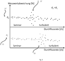
- Fig. 3 shows a schematic graphic with two diagrams on the dependence of the measured value deviation on the prevailing flow profile or on the flow rate, for example for a Newtonian liquid for the two subsections 11, 11 'with the two cross sections d 1 and d 2 , where d 1 > d 2 , as in Fig. 2 shown.
- v For low local flow velocities v there is rather a laminar flow profile and for high flow velocities rather a turbulent flow profile.
- Between these two flow profiles there is a transition area 12, 12 '. Because for a given flow rate the flow velocities and especially Reynolds numbers in the two However, if sections 11, 11 'are not the same, the transition area 12, 12' for the two sections 11, 11 'is at different flow rates.
- the flow velocity in the first section 11 with the larger cross section d 1 is slower in the ratio d 2 2 / d 1 2 than that in the second section 11 'with the smaller cross section d 2 . Accordingly, turbulence occurs in the first section 11 only at higher flow rates, since the critical Reynolds number is exceeded at higher flow rates compared to section 11 '. As a consequence, the transition area 12 for the first section 11 'is at higher flow rates than the transition area 12' for the second section 11 '.
- the considerations here primarily relate to the flow rate.
- the product of flow velocity and diameter is actually decisive for the flow profile. However, since the flow rate at a given flow rate is inversely proportional to the square of the diameter as stated above, the two variables are not independent of one another and in particular the change in speed outweighs the change in diameter with regard to the effect on the Reynolds number.
- the flow rate is determined for both sections 11, 11 'in a first step. Using experimentally determined or stored on the storage unit or using mathematical models Fluid-specific parameters and / or characteristic curves can then again be inferred from the flow rate of the prevailing flow profile.
- the conductivity of the fluid is determined in the present example. This procedure is not absolutely necessary according to the invention, but increases the measurement accuracy under certain circumstances, in particular for fluids with low electrical conductivity. If the conductivity is low, the first section 11 with the larger cross section d 1 is selected, since in this case the speed-dependent signal noise increases more than the measurement signal with increasing flow velocity.
- the choice of subsection 11, 11 ' is determined only by the prevailing flow profile. If the given flow rate is such that there is only a very low flow rate in the first section 11 (d 1 > d 2 ), the second section 12a with the smaller diameter d 2 is selected. In this case the flow rate is highest there, but still in the laminar range. The measuring accuracy is increased accordingly. For low, but somewhat higher flow rates, the transition region 12a already begins in the second subsection 11 '(d 2 ), which is why the first subsection 11 with the larger cross section d 1 is selected, for which the flow profile is still laminar.
- the transition region 12 begins in the first subsection 11 (d 1 ), while a turbulent flow already exists in the second subsection 11a with the smaller cross section d 2 .
- the second section 11 ' is selected accordingly, since the flow profile for it now lies outside the transition region 12, 12'.
- this block diagram can be expanded as desired if, for example, more than two subsections 11, 11 'are used, if more than one pair of measuring electrodes 8, 8' is provided in at least one of the subsections 12, 12 ', or if the transition areas 12, 12 'in the different sections 11, 11' are not at different intervals for the flow rate, and an averaging must be carried out accordingly.
Landscapes
- Physics & Mathematics (AREA)
- Fluid Mechanics (AREA)
- General Physics & Mathematics (AREA)
- Electromagnetism (AREA)
- Engineering & Computer Science (AREA)
- Power Engineering (AREA)
- Measuring Volume Flow (AREA)
Claims (12)
- Dispositif (1) exécuté en vue de la mesure du débit d'un fluide en écoulement d'après le principe de mesure magnéto-inductif, avec(I) un tube de mesure (3) avec au moins deux sections partielles (11, 11') consécutives dans le sens d'écoulement du fluide, les sections partielles (11, 11') se distinguant en termes de diamètre et/ou de géométrie de la surface transversale, de telle sorte que pour un débit donné, différentes vitesses d'écoulement du fluide prédominent dans les aux moins deux sections partielles,(II) au moins un système magnétique (9, 9') avec au moins deux bobines pour la génération d'un champ magnétique (10) pour l'essentiel perpendiculaire au sens d'écoulement du fluide,(III) au moins deux paires d'électrodes de mesure (8, 8') destinées au prélèvement de la tension induite,
au moins une paire d'électrodes de mesure (8) étant disposée dans une première section partielle (11) et une deuxième paire d'électrode de mesure (8') dans une deuxième section partielle (11'),
chaque paire d'électrodes de mesure (8, 8') comprenant une première et une deuxième électrode de mesure,
les électrodes de mesure se faisant face dans ou sur le tube de mesure et la ligne de liaison respective des électrodes de mesure étant orientées verticalement à l'axe de tube et perpendiculairement au champ magnétique (10),
et(IV) une unité électronique (6) destinée à la mesure et/ou à l'évaluation de signaux, ainsi qu'à l'alimentation des bobines,
l'unité électronique (6) étant conçue de telle sorte
à déterminer pour chaque section partielle (11, 11') à partir de la tension induite la vitesse d'écoulement du fluide et/ou le débit,
à déterminer pour chaque section partielle (11, 11') une zone de transition entre l'écoulement laminaire et l'écoulement turbulent,
à contrôler, pour chaque section partielle, si la zone de transition entre l'écoulement laminaire et l'écoulement turbulent est présente lors d'une mesure, à sélectionner, pour la détermination du débit, une section partielle (11, 11') dans laquelle le profil d'écoulement prédominant se situe pour l'essentiel en dehors de la zone de transition (12, 12') respective entre l'écoulement laminaire et l'écoulement turbulent. - Dispositif selon la revendication 1,
pour lequel est attribuée à l'unité électronique (6) une unité de mémoire dans laquelle sont enregistrés des paramètres et/ou des courbes caractéristiques spécifiques au fluide et/ou au tube de mesure, lesquels sont déterminés expérimentalement ou calculés à l'aide de modèles mathématiques,
et pour lequel l'unité électronique (6) est conçue de telle sorte à déterminer le profil d'écoulement prédominant selon un modèle mathématique appliqué à partir de la vitesse d'écoulement du fluide en utilisant les paramètres et/ou les courbes caractéristiques pour chaque sous-section (11, 11'). - Dispositif selon l'une des revendications précédentes,
pour lequel un élément capteur est prévu pour mesurer la conductivité électrique du fluide,
et pour lequel l'unité électronique (6) est conçue de telle manière que pour les fluides ayant une composition pour laquelle le bruit de signal dans la gamme de débit pertinente pour la mesure augmente plus fortement avec la vitesse d'écoulement croissante que le signal de mesure, notamment dans le cas de fluides ayant une faible conductivité électrique, la paire d'électrodes de mesure (8, 8') disposée dans la section (11) avec la plus grande section transversale étant utilisée pour déterminer le débit. - Dispositif selon l'une des revendications précédentes,
pour lequel les différentes électrodes de mesure présentent des géométries différentes, notamment une géométrie pointue, en forme d'épingle, cylindrique, conique ou en forme de tête de champignon. - Dispositif selon l'une des revendications précédentes,
pour lequel au moins deux paires d'électrodes de mesure (8, 8a, 8', 8a') sont installées sur au moins une section partielle (11, 11'). - Dispositif selon l'une des revendications précédentes,
pour lequel le système magnétique (9, 9') est construit de telle sorte à s'étendre le long de toutes les sections partielles (11, 11', ...). - Dispositif selon l'une des revendications 1 à 7,
pour lequel un système magnétique (9, 9a, 9', 9a') est prévu pour chaque section partielle (11, 11'). - Procédé destiné à la mesure d'un fluide en écoulement selon le principe de mesure magnéto-inductif, avec(I) un tube de mesure (3), lequel est composé d'au moins deux sections partielles (11, 11') dans le sens d'écoulement du fluide, les sections partielles (11, 11') se distinguant en termes de diamètre et/ou de géométrie de la surface transversale, de telle sorte que pour un débit donné, différentes vitesses d'écoulement du fluide prédominent dans les aux moins deux sections partielles,(II) un champ magnétique (10) pour l'essentiel perpendiculaire au sens d'écoulement du fluide étant généré, lequel champ traverse le tube de mesure (3),(III) la tension induite étant prélevée dans chaque section partielle (11, 11'), et(IV) la vitesse d'écoulement du fluide et/ou le débit étant déterminés pour chaque section partielle (11, 11') à partir de la tension induite,
une zone partielle entre un écoulement laminaire et un écoulement turbulent étant déterminée pour chaque section partielle,
une vérification étant effectuée pour chaque section partielle, à savoir si la zone de transition entre l'écoulement laminaire et l'écoulement turbulent est présente lors d'une mesure,
une sélection d'une section partielle (11, 11') étant effectuée pour la détermination du débit, section dans laquelle le profil d'écoulement prédominant se situe pour l'essentiel en hors de la zone de transition (12, 12') respective entre l'écoulement laminaire et l'écoulement turbulent. - Procédé selon la revendication 8,
pour lequel le profil d'écoulement prédominant selon le modèle mathématique appliqué est déterminé à partir de la vitesse d'écoulement du fluide sur la base de paramètres et/ou de courbes caractéristiques spécifiques au fluide et/ou au tube de mesure pour chaque section (11, 11'), lesquels paramètres et/ou courbes sont déterminés ou calculés expérimentalement à l'aide de modèles mathématiques, stockés dans une unité de mémoire. - Procédé selon l'une des revendications 8 ou 9,
pour lequel on utilise, en présence de débits faibles, la paire d'électrodes de mesure (8') qui est disposée dans la section partielle (11') ayant la plus petite section transversale. - Procédé selon l'une des revendications 8 à 10,
pour lequel on utilise, en présence de débits faibles, la paire d'électrodes de mesure (8) qui est disposée dans la section partielle (11) ayant la plus grande section transversale. - Procédé selon l'une des revendications 8 à 11,
pour lequel, dans le cas de fluides ayant une composition dans laquelle le bruit de signal augmente, avec une vitesse d'écoulement croissante - dans la gamme de débit pertinente pour la mesure - plus fortement que le signal de mesure, notamment dans le cas de fluides ayant une conductivité électrique faible, on utilise, pour déterminer le débit, la paire d'électrodes de mesure (8, 8') qui est disposée dans la section partielle (11) ayant la plus grande section transversale.
Applications Claiming Priority (2)
| Application Number | Priority Date | Filing Date | Title |
|---|---|---|---|
| DE102014111047.1A DE102014111047B4 (de) | 2014-08-04 | 2014-08-04 | Magnetisch-induktives Durchflussmessgerät mit mehreren Messelektrodenpaaren und unterschiedlichen Messrohrquerschnitten und Verfahren zur Messung des Durchflusses |
| PCT/EP2015/067638 WO2016020277A1 (fr) | 2014-08-04 | 2015-07-31 | Débitmètre à induction magnétique comprenant plusieurs paires d'électrodes de mesure et divers segments transversaux de tubes de mesure |
Publications (2)
| Publication Number | Publication Date |
|---|---|
| EP3177897A1 EP3177897A1 (fr) | 2017-06-14 |
| EP3177897B1 true EP3177897B1 (fr) | 2020-04-01 |
Family
ID=53783714
Family Applications (1)
| Application Number | Title | Priority Date | Filing Date |
|---|---|---|---|
| EP15747437.0A Active EP3177897B1 (fr) | 2014-08-04 | 2015-07-31 | Débitmètre magnétique inductif avec plusieurs paires d'électrodes de mesure et avec conduites aux sections transversales différentes |
Country Status (5)
| Country | Link |
|---|---|
| US (1) | US20170219399A1 (fr) |
| EP (1) | EP3177897B1 (fr) |
| CN (1) | CN106574858B (fr) |
| DE (1) | DE102014111047B4 (fr) |
| WO (1) | WO2016020277A1 (fr) |
Families Citing this family (5)
| Publication number | Priority date | Publication date | Assignee | Title |
|---|---|---|---|---|
| CN107449935A (zh) * | 2017-07-17 | 2017-12-08 | 中国石油化工股份有限公司 | 煤线速度计 |
| CN108469282A (zh) * | 2018-03-02 | 2018-08-31 | 杭州云谷科技股份有限公司 | 一种高精度低功耗电磁式流量传感装置 |
| US10556102B1 (en) * | 2018-08-13 | 2020-02-11 | Biosense Webster (Israel) Ltd. | Automatic adjustment of electrode surface impedances in multi-electrode catheters |
| US11365995B2 (en) * | 2018-09-28 | 2022-06-21 | Georg Fischer Signet Llc | Magnetic flowmeter including auxiliary electrodes upstream and downstream of the pair of measuring electrodes and an adjustable brace |
| DE102018132935A1 (de) | 2018-12-19 | 2020-06-25 | Endress+Hauser Flowtec Ag | Magnetisch-induktives Durchflussmessgerät und Messstelle |
Citations (2)
| Publication number | Priority date | Publication date | Assignee | Title |
|---|---|---|---|---|
| DE3630885A1 (de) * | 1986-09-11 | 1988-03-17 | Turbo Werk Messtechnik Gmbh | Induktiver durchflussmesser |
| DE4104451A1 (de) * | 1991-02-14 | 1992-08-27 | Vollmar Oskar Gmbh | Regenueberlaufbauwerk mit einer messeinrichtung zur bestimmung der ueberlaufwassermenge |
Family Cites Families (22)
| Publication number | Priority date | Publication date | Assignee | Title |
|---|---|---|---|---|
| DE1914335C3 (de) * | 1969-03-21 | 1973-08-02 | Fa Ludwig Krohne, 4100 Duisburg | Induktiver strömungsmesser |
| JPS58176520A (ja) * | 1982-04-10 | 1983-10-17 | Yamatake Honeywell Co Ltd | 電磁流量計 |
| JPS62187181A (ja) * | 1986-02-12 | 1987-08-15 | 株式会社東芝 | 導電性棒体のセラミツクス体への内嵌封着方法 |
| EP0305609B1 (fr) * | 1987-08-05 | 1992-05-20 | MARSH-McBIRNEY, INC. | Capteur de vitesse moyenne pour la mesure de débit de fluide dans un conduit |
| US4688432A (en) * | 1986-02-27 | 1987-08-25 | Marsh Lawrence B | Averaging velocity sensor for measuring fluid flow in a conduit |
| EP0274768A1 (fr) * | 1986-11-25 | 1988-07-20 | Pumptech N.V. | Débitmètre électromagnétique pour fluides conductifs ou diélectriques et son application en particulier dans la pétrochimie |
| US4755757A (en) * | 1987-03-06 | 1988-07-05 | Southwest Research Institute | Fluid leak detection system for determining the fate of fluid leakage through a geomembrane |
| US4912838A (en) * | 1987-12-25 | 1990-04-03 | Yamatake-Honeywell Co., Ltd. | Method of manufacturing electrode for electromagnetic flowmeter |
| DE4010728C2 (de) * | 1990-04-03 | 1999-05-20 | Fischer & Porter Gmbh | Magnetisch induktiver Durchflußmesser |
| US5417118A (en) * | 1993-07-15 | 1995-05-23 | Lew; Hyok S. | Magnetic flowmeter determining flow rate from phase angle difference |
| US6463807B1 (en) * | 2000-11-02 | 2002-10-15 | Murray F. Feller | Magnetic flow sensor and method |
| US6530285B1 (en) * | 2001-08-20 | 2003-03-11 | Murray F. Feller | Magnetic flow sensor probe |
| DE10244647A1 (de) * | 2002-09-25 | 2004-04-08 | Ketelsen, Broder | Induktiver Durchflußmesser für elektrisch leitfähige Flüssigkeiten |
| JP4527484B2 (ja) * | 2004-09-22 | 2010-08-18 | 株式会社山武 | 状態検出装置 |
| JP4754932B2 (ja) * | 2005-10-17 | 2011-08-24 | 株式会社山武 | 電磁流量計 |
| DE102006014679A1 (de) | 2006-03-28 | 2007-10-04 | Endress + Hauser Flowtec Ag | Magnetisch-induktives Durchflussmessgerät |
| DE102007011394A1 (de) * | 2007-03-07 | 2008-09-11 | Fachhochschule Kiel | Verfahren zur Messung der Fließgeschwindigkeit eines Mediums unter Anlegen eines Magnetfelds an das durchsetzte Meßvolumen |
| DE102007014469A1 (de) * | 2007-03-22 | 2008-09-25 | Endress + Hauser Flowtec Ag | Verfahren zur vorausschauenden Wartung und/oder Verfahren zur Bestimmung der elektrischen Leitfähigkeit bei einem magnetischinduktiven Durchflussmessgerät |
| DE102008059067A1 (de) * | 2008-11-26 | 2010-06-02 | Krohne Ag | Magnetisch-induktives Durchflußmeßgerät |
| DE102011119982A1 (de) | 2011-12-02 | 2013-06-06 | Krohne Ag | Magnetisch-induktives Durchflussmessgerät |
| US9021890B2 (en) * | 2012-09-26 | 2015-05-05 | Rosemount Inc. | Magnetic flowmeter with multiple coils |
| DE102012221616B4 (de) * | 2012-11-27 | 2015-03-12 | Siemens Aktiengesellschaft | Magnetisch induktiver Durchflussmesser |
-
2014
- 2014-08-04 DE DE102014111047.1A patent/DE102014111047B4/de active Active
-
2015
- 2015-07-31 US US15/500,694 patent/US20170219399A1/en not_active Abandoned
- 2015-07-31 EP EP15747437.0A patent/EP3177897B1/fr active Active
- 2015-07-31 CN CN201580042131.9A patent/CN106574858B/zh active Active
- 2015-07-31 WO PCT/EP2015/067638 patent/WO2016020277A1/fr active Application Filing
Patent Citations (2)
| Publication number | Priority date | Publication date | Assignee | Title |
|---|---|---|---|---|
| DE3630885A1 (de) * | 1986-09-11 | 1988-03-17 | Turbo Werk Messtechnik Gmbh | Induktiver durchflussmesser |
| DE4104451A1 (de) * | 1991-02-14 | 1992-08-27 | Vollmar Oskar Gmbh | Regenueberlaufbauwerk mit einer messeinrichtung zur bestimmung der ueberlaufwassermenge |
Also Published As
| Publication number | Publication date |
|---|---|
| WO2016020277A1 (fr) | 2016-02-11 |
| DE102014111047A1 (de) | 2016-02-04 |
| DE102014111047B4 (de) | 2016-02-11 |
| CN106574858A (zh) | 2017-04-19 |
| US20170219399A1 (en) | 2017-08-03 |
| EP3177897A1 (fr) | 2017-06-14 |
| CN106574858B (zh) | 2020-02-28 |
Similar Documents
| Publication | Publication Date | Title |
|---|---|---|
| EP3177897B1 (fr) | Débitmètre magnétique inductif avec plusieurs paires d'électrodes de mesure et avec conduites aux sections transversales différentes | |
| EP3775791B1 (fr) | Compteur de débit magnetique-inductif et unité de mesure comportant un tel compteur de débit magnetique-inductif | |
| EP3194900B1 (fr) | Procédé de fabrication d'un débitmètre à induction magnétique de section transversale réduite | |
| EP2227677B1 (fr) | Système de mesure pour un fluide s'écoulant dans une conduite de processus | |
| EP2600119A1 (fr) | Débitmètre à induction magnétique | |
| EP1893951B1 (fr) | Appareil de mesure de debit a induction magnetique | |
| EP3899439B1 (fr) | Procédé de dimensionnement d'un débitmètre magnétique-inductif | |
| EP3891475B1 (fr) | Débitmètre magnetique inductif | |
| WO2016041723A1 (fr) | Débitmètre à induction magnétique pourvu d'un système magnétique à quatre bobines | |
| EP4022259B1 (fr) | Débitmètre à induction magnétique et procédé de fonctionnement d'un débitmètre à induction magnétique | |
| EP3325923B1 (fr) | Débitmètre selon le principe de comptage de tourbillons | |
| DE102017001049A1 (de) | Wirkdruckgeber | |
| DE102014113406A1 (de) | Magnetisch-induktives Durchflussmessgerät mit Einschub | |
| DE102020114515A1 (de) | Magnetisch-induktive Durchflussmessvorrichtung | |
| DE102015112930B4 (de) | Magnetisch-induktives Durchflussmessgerät | |
| DE2702816C3 (de) | Gerät zum Messen des Durchflusses eines Fluids durch eine Leitung | |
| EP4004496B1 (fr) | Débitmètre à induction magnétique et procédé de fonctionnement d'un débitmètre à induction magnétique | |
| WO2024132779A1 (fr) | Débitmètre magnéto-inductif | |
| WO2020200692A1 (fr) | Débitmètre magnéto-inductif | |
| WO2024041812A1 (fr) | Procédé de détermination de fonction de correction | |
| DE102008059510B4 (de) | Infusor und Durchflußmeßgerät | |
| DE202018105414U1 (de) | Strömungsmessung mit Ultraschall | |
| DE202012002451U1 (de) | Sensor zur Messung der Strömungsgeschwindigkeit und des Gasanteils einer Gas-Flüssigkeits-Zweiphasenströmung |
Legal Events
| Date | Code | Title | Description |
|---|---|---|---|
| STAA | Information on the status of an ep patent application or granted ep patent |
Free format text: STATUS: THE INTERNATIONAL PUBLICATION HAS BEEN MADE |
|
| PUAI | Public reference made under article 153(3) epc to a published international application that has entered the european phase |
Free format text: ORIGINAL CODE: 0009012 |
|
| STAA | Information on the status of an ep patent application or granted ep patent |
Free format text: STATUS: REQUEST FOR EXAMINATION WAS MADE |
|
| 17P | Request for examination filed |
Effective date: 20170119 |
|
| AK | Designated contracting states |
Kind code of ref document: A1 Designated state(s): AL AT BE BG CH CY CZ DE DK EE ES FI FR GB GR HR HU IE IS IT LI LT LU LV MC MK MT NL NO PL PT RO RS SE SI SK SM TR |
|
| AX | Request for extension of the european patent |
Extension state: BA ME |
|
| DAV | Request for validation of the european patent (deleted) | ||
| DAX | Request for extension of the european patent (deleted) | ||
| STAA | Information on the status of an ep patent application or granted ep patent |
Free format text: STATUS: EXAMINATION IS IN PROGRESS |
|
| 17Q | First examination report despatched |
Effective date: 20180212 |
|
| GRAP | Despatch of communication of intention to grant a patent |
Free format text: ORIGINAL CODE: EPIDOSNIGR1 |
|
| STAA | Information on the status of an ep patent application or granted ep patent |
Free format text: STATUS: GRANT OF PATENT IS INTENDED |
|
| RIC1 | Information provided on ipc code assigned before grant |
Ipc: G01F 7/00 20060101ALI20191028BHEP Ipc: G01F 1/58 20060101AFI20191028BHEP |
|
| INTG | Intention to grant announced |
Effective date: 20191119 |
|
| RIN1 | Information on inventor provided before grant (corrected) |
Inventor name: BAEHR, GUENTHER Inventor name: KUENG, THOMAS Inventor name: VOIGT, FRANK |
|
| GRAS | Grant fee paid |
Free format text: ORIGINAL CODE: EPIDOSNIGR3 |
|
| GRAA | (expected) grant |
Free format text: ORIGINAL CODE: 0009210 |
|
| STAA | Information on the status of an ep patent application or granted ep patent |
Free format text: STATUS: THE PATENT HAS BEEN GRANTED |
|
| AK | Designated contracting states |
Kind code of ref document: B1 Designated state(s): AL AT BE BG CH CY CZ DE DK EE ES FI FR GB GR HR HU IE IS IT LI LT LU LV MC MK MT NL NO PL PT RO RS SE SI SK SM TR |
|
| REG | Reference to a national code |
Ref country code: GB Ref legal event code: FG4D Free format text: NOT ENGLISH |
|
| REG | Reference to a national code |
Ref country code: AT Ref legal event code: REF Ref document number: 1251945 Country of ref document: AT Kind code of ref document: T Effective date: 20200415 Ref country code: CH Ref legal event code: EP |
|
| REG | Reference to a national code |
Ref country code: DE Ref legal event code: R096 Ref document number: 502015012166 Country of ref document: DE |
|
| REG | Reference to a national code |
Ref country code: IE Ref legal event code: FG4D Free format text: LANGUAGE OF EP DOCUMENT: GERMAN |
|
| REG | Reference to a national code |
Ref country code: NL Ref legal event code: FP |
|
| PG25 | Lapsed in a contracting state [announced via postgrant information from national office to epo] |
Ref country code: BG Free format text: LAPSE BECAUSE OF FAILURE TO SUBMIT A TRANSLATION OF THE DESCRIPTION OR TO PAY THE FEE WITHIN THE PRESCRIBED TIME-LIMIT Effective date: 20200701 |
|
| REG | Reference to a national code |
Ref country code: LT Ref legal event code: MG4D |
|
| PG25 | Lapsed in a contracting state [announced via postgrant information from national office to epo] |
Ref country code: SE Free format text: LAPSE BECAUSE OF FAILURE TO SUBMIT A TRANSLATION OF THE DESCRIPTION OR TO PAY THE FEE WITHIN THE PRESCRIBED TIME-LIMIT Effective date: 20200401 Ref country code: IS Free format text: LAPSE BECAUSE OF FAILURE TO SUBMIT A TRANSLATION OF THE DESCRIPTION OR TO PAY THE FEE WITHIN THE PRESCRIBED TIME-LIMIT Effective date: 20200801 Ref country code: LT Free format text: LAPSE BECAUSE OF FAILURE TO SUBMIT A TRANSLATION OF THE DESCRIPTION OR TO PAY THE FEE WITHIN THE PRESCRIBED TIME-LIMIT Effective date: 20200401 Ref country code: PT Free format text: LAPSE BECAUSE OF FAILURE TO SUBMIT A TRANSLATION OF THE DESCRIPTION OR TO PAY THE FEE WITHIN THE PRESCRIBED TIME-LIMIT Effective date: 20200817 Ref country code: CZ Free format text: LAPSE BECAUSE OF FAILURE TO SUBMIT A TRANSLATION OF THE DESCRIPTION OR TO PAY THE FEE WITHIN THE PRESCRIBED TIME-LIMIT Effective date: 20200401 Ref country code: NO Free format text: LAPSE BECAUSE OF FAILURE TO SUBMIT A TRANSLATION OF THE DESCRIPTION OR TO PAY THE FEE WITHIN THE PRESCRIBED TIME-LIMIT Effective date: 20200701 Ref country code: GR Free format text: LAPSE BECAUSE OF FAILURE TO SUBMIT A TRANSLATION OF THE DESCRIPTION OR TO PAY THE FEE WITHIN THE PRESCRIBED TIME-LIMIT Effective date: 20200702 Ref country code: FI Free format text: LAPSE BECAUSE OF FAILURE TO SUBMIT A TRANSLATION OF THE DESCRIPTION OR TO PAY THE FEE WITHIN THE PRESCRIBED TIME-LIMIT Effective date: 20200401 |
|
| PG25 | Lapsed in a contracting state [announced via postgrant information from national office to epo] |
Ref country code: RS Free format text: LAPSE BECAUSE OF FAILURE TO SUBMIT A TRANSLATION OF THE DESCRIPTION OR TO PAY THE FEE WITHIN THE PRESCRIBED TIME-LIMIT Effective date: 20200401 Ref country code: HR Free format text: LAPSE BECAUSE OF FAILURE TO SUBMIT A TRANSLATION OF THE DESCRIPTION OR TO PAY THE FEE WITHIN THE PRESCRIBED TIME-LIMIT Effective date: 20200401 Ref country code: LV Free format text: LAPSE BECAUSE OF FAILURE TO SUBMIT A TRANSLATION OF THE DESCRIPTION OR TO PAY THE FEE WITHIN THE PRESCRIBED TIME-LIMIT Effective date: 20200401 |
|
| PG25 | Lapsed in a contracting state [announced via postgrant information from national office to epo] |
Ref country code: AL Free format text: LAPSE BECAUSE OF FAILURE TO SUBMIT A TRANSLATION OF THE DESCRIPTION OR TO PAY THE FEE WITHIN THE PRESCRIBED TIME-LIMIT Effective date: 20200401 |
|
| REG | Reference to a national code |
Ref country code: DE Ref legal event code: R097 Ref document number: 502015012166 Country of ref document: DE |
|
| PG25 | Lapsed in a contracting state [announced via postgrant information from national office to epo] |
Ref country code: SM Free format text: LAPSE BECAUSE OF FAILURE TO SUBMIT A TRANSLATION OF THE DESCRIPTION OR TO PAY THE FEE WITHIN THE PRESCRIBED TIME-LIMIT Effective date: 20200401 Ref country code: EE Free format text: LAPSE BECAUSE OF FAILURE TO SUBMIT A TRANSLATION OF THE DESCRIPTION OR TO PAY THE FEE WITHIN THE PRESCRIBED TIME-LIMIT Effective date: 20200401 Ref country code: IT Free format text: LAPSE BECAUSE OF FAILURE TO SUBMIT A TRANSLATION OF THE DESCRIPTION OR TO PAY THE FEE WITHIN THE PRESCRIBED TIME-LIMIT Effective date: 20200401 Ref country code: RO Free format text: LAPSE BECAUSE OF FAILURE TO SUBMIT A TRANSLATION OF THE DESCRIPTION OR TO PAY THE FEE WITHIN THE PRESCRIBED TIME-LIMIT Effective date: 20200401 Ref country code: ES Free format text: LAPSE BECAUSE OF FAILURE TO SUBMIT A TRANSLATION OF THE DESCRIPTION OR TO PAY THE FEE WITHIN THE PRESCRIBED TIME-LIMIT Effective date: 20200401 Ref country code: DK Free format text: LAPSE BECAUSE OF FAILURE TO SUBMIT A TRANSLATION OF THE DESCRIPTION OR TO PAY THE FEE WITHIN THE PRESCRIBED TIME-LIMIT Effective date: 20200401 |
|
| PLBE | No opposition filed within time limit |
Free format text: ORIGINAL CODE: 0009261 |
|
| STAA | Information on the status of an ep patent application or granted ep patent |
Free format text: STATUS: NO OPPOSITION FILED WITHIN TIME LIMIT |
|
| PG25 | Lapsed in a contracting state [announced via postgrant information from national office to epo] |
Ref country code: SK Free format text: LAPSE BECAUSE OF FAILURE TO SUBMIT A TRANSLATION OF THE DESCRIPTION OR TO PAY THE FEE WITHIN THE PRESCRIBED TIME-LIMIT Effective date: 20200401 Ref country code: PL Free format text: LAPSE BECAUSE OF FAILURE TO SUBMIT A TRANSLATION OF THE DESCRIPTION OR TO PAY THE FEE WITHIN THE PRESCRIBED TIME-LIMIT Effective date: 20200401 Ref country code: MC Free format text: LAPSE BECAUSE OF FAILURE TO SUBMIT A TRANSLATION OF THE DESCRIPTION OR TO PAY THE FEE WITHIN THE PRESCRIBED TIME-LIMIT Effective date: 20200401 |
|
| REG | Reference to a national code |
Ref country code: CH Ref legal event code: PL |
|
| 26N | No opposition filed |
Effective date: 20210112 |
|
| GBPC | Gb: european patent ceased through non-payment of renewal fee |
Effective date: 20200731 |
|
| REG | Reference to a national code |
Ref country code: BE Ref legal event code: MM Effective date: 20200731 |
|
| PG25 | Lapsed in a contracting state [announced via postgrant information from national office to epo] |
Ref country code: GB Free format text: LAPSE BECAUSE OF NON-PAYMENT OF DUE FEES Effective date: 20200731 Ref country code: CH Free format text: LAPSE BECAUSE OF NON-PAYMENT OF DUE FEES Effective date: 20200731 Ref country code: FR Free format text: LAPSE BECAUSE OF NON-PAYMENT OF DUE FEES Effective date: 20200731 Ref country code: LU Free format text: LAPSE BECAUSE OF NON-PAYMENT OF DUE FEES Effective date: 20200731 Ref country code: LI Free format text: LAPSE BECAUSE OF NON-PAYMENT OF DUE FEES Effective date: 20200731 |
|
| PG25 | Lapsed in a contracting state [announced via postgrant information from national office to epo] |
Ref country code: SI Free format text: LAPSE BECAUSE OF FAILURE TO SUBMIT A TRANSLATION OF THE DESCRIPTION OR TO PAY THE FEE WITHIN THE PRESCRIBED TIME-LIMIT Effective date: 20200401 Ref country code: BE Free format text: LAPSE BECAUSE OF NON-PAYMENT OF DUE FEES Effective date: 20200731 |
|
| PG25 | Lapsed in a contracting state [announced via postgrant information from national office to epo] |
Ref country code: IE Free format text: LAPSE BECAUSE OF NON-PAYMENT OF DUE FEES Effective date: 20200731 |
|
| REG | Reference to a national code |
Ref country code: AT Ref legal event code: MM01 Ref document number: 1251945 Country of ref document: AT Kind code of ref document: T Effective date: 20200731 |
|
| PG25 | Lapsed in a contracting state [announced via postgrant information from national office to epo] |
Ref country code: AT Free format text: LAPSE BECAUSE OF NON-PAYMENT OF DUE FEES Effective date: 20200731 |
|
| PG25 | Lapsed in a contracting state [announced via postgrant information from national office to epo] |
Ref country code: TR Free format text: LAPSE BECAUSE OF FAILURE TO SUBMIT A TRANSLATION OF THE DESCRIPTION OR TO PAY THE FEE WITHIN THE PRESCRIBED TIME-LIMIT Effective date: 20200401 Ref country code: MT Free format text: LAPSE BECAUSE OF FAILURE TO SUBMIT A TRANSLATION OF THE DESCRIPTION OR TO PAY THE FEE WITHIN THE PRESCRIBED TIME-LIMIT Effective date: 20200401 Ref country code: CY Free format text: LAPSE BECAUSE OF FAILURE TO SUBMIT A TRANSLATION OF THE DESCRIPTION OR TO PAY THE FEE WITHIN THE PRESCRIBED TIME-LIMIT Effective date: 20200401 |
|
| PG25 | Lapsed in a contracting state [announced via postgrant information from national office to epo] |
Ref country code: MK Free format text: LAPSE BECAUSE OF FAILURE TO SUBMIT A TRANSLATION OF THE DESCRIPTION OR TO PAY THE FEE WITHIN THE PRESCRIBED TIME-LIMIT Effective date: 20200401 |
|
| P01 | Opt-out of the competence of the unified patent court (upc) registered |
Effective date: 20230601 |
|
| PGFP | Annual fee paid to national office [announced via postgrant information from national office to epo] |
Ref country code: DE Payment date: 20230719 Year of fee payment: 9 |
|
| PGFP | Annual fee paid to national office [announced via postgrant information from national office to epo] |
Ref country code: NL Payment date: 20240719 Year of fee payment: 10 |