EP3177897B1 - Magnetic inductive flow meter including multiple pairs of measurement electrodes and different measurement pipe cross sections - Google Patents
Magnetic inductive flow meter including multiple pairs of measurement electrodes and different measurement pipe cross sections Download PDFInfo
- Publication number
- EP3177897B1 EP3177897B1 EP15747437.0A EP15747437A EP3177897B1 EP 3177897 B1 EP3177897 B1 EP 3177897B1 EP 15747437 A EP15747437 A EP 15747437A EP 3177897 B1 EP3177897 B1 EP 3177897B1
- Authority
- EP
- European Patent Office
- Prior art keywords
- flow
- measuring
- subsection
- fluid
- section
- Prior art date
- Legal status (The legal status is an assumption and is not a legal conclusion. Google has not performed a legal analysis and makes no representation as to the accuracy of the status listed.)
- Active
Links
- 238000005259 measurement Methods 0.000 title claims description 34
- 230000001939 inductive effect Effects 0.000 title claims description 4
- 239000012530 fluid Substances 0.000 claims description 60
- 230000007704 transition Effects 0.000 claims description 26
- 238000000034 method Methods 0.000 claims description 15
- 230000001965 increasing effect Effects 0.000 claims description 10
- 238000013178 mathematical model Methods 0.000 claims description 8
- 238000011156 evaluation Methods 0.000 claims description 4
- 235000001674 Agaricus brunnescens Nutrition 0.000 claims 1
- XLYOFNOQVPJJNP-UHFFFAOYSA-N water Substances O XLYOFNOQVPJJNP-UHFFFAOYSA-N 0.000 description 7
- 238000013461 design Methods 0.000 description 4
- 238000010586 diagram Methods 0.000 description 4
- 238000010079 rubber tapping Methods 0.000 description 4
- 238000013459 approach Methods 0.000 description 2
- 230000008859 change Effects 0.000 description 2
- 238000001514 detection method Methods 0.000 description 2
- 238000000926 separation method Methods 0.000 description 2
- 238000012935 Averaging Methods 0.000 description 1
- 230000001154 acute effect Effects 0.000 description 1
- 230000008901 benefit Effects 0.000 description 1
- 238000010276 construction Methods 0.000 description 1
- 230000008878 coupling Effects 0.000 description 1
- 238000010168 coupling process Methods 0.000 description 1
- 238000005859 coupling reaction Methods 0.000 description 1
- 230000001419 dependent effect Effects 0.000 description 1
- 230000000694 effects Effects 0.000 description 1
- 238000005516 engineering process Methods 0.000 description 1
- 230000005284 excitation Effects 0.000 description 1
- 230000006698 induction Effects 0.000 description 1
- 150000002500 ions Chemical class 0.000 description 1
- 239000007788 liquid Substances 0.000 description 1
- 239000000463 material Substances 0.000 description 1
- 238000012544 monitoring process Methods 0.000 description 1
- 230000000704 physical effect Effects 0.000 description 1
- 230000002265 prevention Effects 0.000 description 1
- 230000008569 process Effects 0.000 description 1
- 230000009467 reduction Effects 0.000 description 1
- 239000000126 substance Substances 0.000 description 1
- 230000003746 surface roughness Effects 0.000 description 1
Images


Classifications
-
- G—PHYSICS
- G01—MEASURING; TESTING
- G01F—MEASURING VOLUME, VOLUME FLOW, MASS FLOW OR LIQUID LEVEL; METERING BY VOLUME
- G01F1/00—Measuring the volume flow or mass flow of fluid or fluent solid material wherein the fluid passes through a meter in a continuous flow
- G01F1/56—Measuring the volume flow or mass flow of fluid or fluent solid material wherein the fluid passes through a meter in a continuous flow by using electric or magnetic effects
- G01F1/58—Measuring the volume flow or mass flow of fluid or fluent solid material wherein the fluid passes through a meter in a continuous flow by using electric or magnetic effects by electromagnetic flowmeters
- G01F1/588—Measuring the volume flow or mass flow of fluid or fluent solid material wherein the fluid passes through a meter in a continuous flow by using electric or magnetic effects by electromagnetic flowmeters combined constructions of electrodes, coils or magnetic circuits, accessories therefor
-
- G—PHYSICS
- G01—MEASURING; TESTING
- G01F—MEASURING VOLUME, VOLUME FLOW, MASS FLOW OR LIQUID LEVEL; METERING BY VOLUME
- G01F1/00—Measuring the volume flow or mass flow of fluid or fluent solid material wherein the fluid passes through a meter in a continuous flow
- G01F1/56—Measuring the volume flow or mass flow of fluid or fluent solid material wherein the fluid passes through a meter in a continuous flow by using electric or magnetic effects
- G01F1/58—Measuring the volume flow or mass flow of fluid or fluent solid material wherein the fluid passes through a meter in a continuous flow by using electric or magnetic effects by electromagnetic flowmeters
- G01F1/584—Measuring the volume flow or mass flow of fluid or fluent solid material wherein the fluid passes through a meter in a continuous flow by using electric or magnetic effects by electromagnetic flowmeters constructions of electrodes, accessories therefor
-
- G—PHYSICS
- G01—MEASURING; TESTING
- G01F—MEASURING VOLUME, VOLUME FLOW, MASS FLOW OR LIQUID LEVEL; METERING BY VOLUME
- G01F1/00—Measuring the volume flow or mass flow of fluid or fluent solid material wherein the fluid passes through a meter in a continuous flow
- G01F1/56—Measuring the volume flow or mass flow of fluid or fluent solid material wherein the fluid passes through a meter in a continuous flow by using electric or magnetic effects
- G01F1/58—Measuring the volume flow or mass flow of fluid or fluent solid material wherein the fluid passes through a meter in a continuous flow by using electric or magnetic effects by electromagnetic flowmeters
- G01F1/586—Measuring the volume flow or mass flow of fluid or fluent solid material wherein the fluid passes through a meter in a continuous flow by using electric or magnetic effects by electromagnetic flowmeters constructions of coils, magnetic circuits, accessories therefor
-
- G—PHYSICS
- G01—MEASURING; TESTING
- G01F—MEASURING VOLUME, VOLUME FLOW, MASS FLOW OR LIQUID LEVEL; METERING BY VOLUME
- G01F1/00—Measuring the volume flow or mass flow of fluid or fluent solid material wherein the fluid passes through a meter in a continuous flow
- G01F1/56—Measuring the volume flow or mass flow of fluid or fluent solid material wherein the fluid passes through a meter in a continuous flow by using electric or magnetic effects
- G01F1/58—Measuring the volume flow or mass flow of fluid or fluent solid material wherein the fluid passes through a meter in a continuous flow by using electric or magnetic effects by electromagnetic flowmeters
- G01F1/60—Circuits therefor
-
- G—PHYSICS
- G01—MEASURING; TESTING
- G01F—MEASURING VOLUME, VOLUME FLOW, MASS FLOW OR LIQUID LEVEL; METERING BY VOLUME
- G01F7/00—Volume-flow measuring devices with two or more measuring ranges; Compound meters
Definitions
- the invention relates to a device and a method for measuring the flow of a flowing fluid through a measuring tube according to the magnetic-inductive measuring principle.
- Magnetic-inductive flowmeters are widely used in process and automation technology for fluids with an electrical conductivity of around 5 ⁇ S / cm.
- Corresponding flowmeters are sold, for example, by the applicant in a wide variety of embodiments for different areas of application, for example under the name PROMAG.
- the measuring principle is based on Faraday's law of magnetic induction and is known from various publications.
- a magnetic field of a temporally constant strength is generated essentially perpendicular to the direction of flow of the conductive fluid by means of a magnet system attached to a measuring tube section.
- the electrical voltage resulting from this charge separation is tapped off by means of at least one pair of measuring electrodes also fastened in the measuring tube section.
- the tapped voltage is proportional to the flow velocity of the fluid and thus proportional to the volume flow.
- the measuring electrodes should be characterized by sensitive and low-interference measurement signal detection.
- a measuring electrode is usually composed of two parts: an electrode shaft, which is at least almost completely inserted into the wall of the measuring tube, and an electrode head for direct coupling with the fluid and for recording the measuring signal.
- the geometry of the electrode head can be pointed or mushroom-shaped, for example.
- Another approach to increasing the measuring accuracy is to specifically modify the measuring tube itself.
- a division of the measuring tube into an inflow section, a measuring section and an outflow section is disclosed, the three measuring tube sections each having different cross sections.
- a smaller cross section, in particular with a rectangular measuring tube profile, is selected for the measuring tube section than for the other two sections.
- the reduction in cross section then offers the advantage that the flow velocity of the fluid is increased in the area of the measuring section.
- the measurement signal is very low at low flow velocities.
- zero point instabilities can have a more negative influence on the measurement at lower flow velocities.
- a stronger measurement signal is generated by the charge separation achieved due to the magnetic field and correspondingly increased the measurement accuracy.
- Another important aspect concerns the flow profile prevailing in the measuring tube. This depends on the Reynolds number, which in turn depends on the flow velocity, the geometry of the measuring tube and its surface roughness in the inner area, on physical and / or chemical material parameters of the medium, such as the viscosity, and on the inlet conditions of the flowing fluid in the measuring tube in front of the Measuring tube section in which the measuring device is attached depends.
- the flow velocity of the fluid is determined from the cross section of the measuring tube.
- the flow rate which depends on the cross-section of the measuring tube, largely determines the measuring accuracy of the electromagnetic flow measurement.
- the present invention is therefore based on the object of providing a device and a method for measuring the flow rate according to the magnetic-inductive measuring principle, the flow rate of the fluid, on the basis of which the flow rate is determined, for each application, as far as possible, in an optimal range for the flow rate.
- the flow velocities in the at least two sections of the measuring tube are different.
- the section for which the flow rate is in the optimal range for the flow rate can then be selected using various procedures described below.
- a memory unit is assigned to the electronic unit, on which memory unit experimentally determined or fluid-specific and / or measuring tube-specific parameters and / or characteristic curves are stored, and that the electronic unit is designed in such a way that it is based on the Parameters and / or characteristic curves for each section are determined from the flow velocity of the fluid and the cross section of the section, the prevailing flow profile according to an applied mathematical model.
- the electronics unit is further configured such that, as far as possible, it selects the section in which the prevailing flow profile lies outside a transition region between laminar and turbulent flow for determining the flow.
- the electronic unit is designed in such a way that it provides the flow velocities for the various subsections with suitable weighting factors depending on the prevailing flow profile and thus averages the flow velocities in the subsections in order to determine the flow. This procedure makes it possible to compare the two values for the flow rate determined for different flow rates, and to compensate for inaccuracies due to a flow rate which may be too high or too low.
- a sensor element is provided for detecting the electrical conductivity of the fluid.
- the electronics unit should then be designed in such a way that, in the case of fluids with a composition in which the signal noise in the flow range relevant for the measurement increases with increasing flow velocity more than the measurement signal, in particular in the case of fluids with a low electrical conductivity, the pair of measuring electrodes is used to measure the flow is used, which is arranged in the section with the largest cross section.
- the measuring electrodes have different geometries, in particular a pointed, pin-shaped, cylindrical, conical or mushroom-headed geometry.
- the different geometries influence the flowing fluid in different ways, since they protrude differently into the respective section of the measuring tube. Accordingly, the prevailing flow profile is influenced differently depending on the selected geometry of the measuring electrode. Furthermore, the choice of an acute geometry in the section with the larger diameter allows the prevention of Deposits with appropriate media due to the lower flow velocities in this section.
- At least two pairs of measuring electrodes are attached to at least one section.
- this version allows redundant and therefore more precise tapping of the measurement signal.
- the magnet system is constructed in such a way that it extends along all partial sections.
- a separate magnet system can be provided for each section.
- the pair of measuring electrodes which is arranged in the subsection with the smallest cross section, is used at low flow rates.
- the highest flow rate prevails in this section.
- the measuring accuracy is increased accordingly. In the case of water, this concerns, for example, flow velocities of ⁇ 10 cm / s in the sections with a larger diameter.
- the pair of measuring electrodes is used, which is arranged in the section with the largest cross section.
- the flow velocity is lowest there, so that the occurrence of cavitation can be avoided, as is the case in Case of water at flow velocities ⁇ 12m / s can occur.
- the section with a larger diameter can be used. So that the gas bubbles that may occur during cavitation in the partial section with a larger diameter do not lead to faults, the arrangement of the partial sections in the measuring tube in relation to the flow direction should preferably be carried out from partial sections with a larger diameter to those with a smaller diameter.
- FIG. 1 A magnetic-inductive flow meter 1 for measuring the flow of a flowing fluid 2 through a measuring tube 3 is shown.
- the measuring tube is provided with an electrically insulating liner 4 in the area facing the fluid, ie on the inside over the entire length.
- the respective connecting axes of the Measuring electrode pairs 8, 8 ' are each positioned perpendicular to the connecting axis of the field coils 9, 9' on opposite sides of the measuring tube.
- the sensor unit with its respective components such. B, the measuring electrode pairs 8, 8 'and the magnet system 9, 9' is usually at least partially surrounded by a housing 5.
- an electronics unit 6 is also provided which is electrically connected to the field device via a connecting cable 7.
- the electronics unit is used for signal acquisition and / or evaluation and for feeding the coils, and as an interface to the environment, e.g. B. the measured value output or setting of the device.
- Fig. 2 is an example of a measuring tube 3 according to the invention with two sections, a first section 11 with a large cross section d 1 and a second section 11 'with a small cross section d 2 .
- a preferred combination would be given a nominal diameter of DN15 for the first section 11 and DN8 for the second section 11 '.
- the first section 11 there is a first pair of measuring electrodes 8, and in the second section 11 'there is a second pair of measuring electrodes 8'.
- this version is only an example.
- other size ratios can be selected for the different sections 11, 11 ', more than two sections 11, 11' can be used, or at least one further pair of measuring electrodes 8a, 8a 'can be attached to each section 11, 11'.
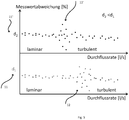
- Fig. 3 shows a schematic graphic with two diagrams on the dependence of the measured value deviation on the prevailing flow profile or on the flow rate, for example for a Newtonian liquid for the two subsections 11, 11 'with the two cross sections d 1 and d 2 , where d 1 > d 2 , as in Fig. 2 shown.
- v For low local flow velocities v there is rather a laminar flow profile and for high flow velocities rather a turbulent flow profile.
- Between these two flow profiles there is a transition area 12, 12 '. Because for a given flow rate the flow velocities and especially Reynolds numbers in the two However, if sections 11, 11 'are not the same, the transition area 12, 12' for the two sections 11, 11 'is at different flow rates.
- the flow velocity in the first section 11 with the larger cross section d 1 is slower in the ratio d 2 2 / d 1 2 than that in the second section 11 'with the smaller cross section d 2 . Accordingly, turbulence occurs in the first section 11 only at higher flow rates, since the critical Reynolds number is exceeded at higher flow rates compared to section 11 '. As a consequence, the transition area 12 for the first section 11 'is at higher flow rates than the transition area 12' for the second section 11 '.
- the considerations here primarily relate to the flow rate.
- the product of flow velocity and diameter is actually decisive for the flow profile. However, since the flow rate at a given flow rate is inversely proportional to the square of the diameter as stated above, the two variables are not independent of one another and in particular the change in speed outweighs the change in diameter with regard to the effect on the Reynolds number.
- the flow rate is determined for both sections 11, 11 'in a first step. Using experimentally determined or stored on the storage unit or using mathematical models Fluid-specific parameters and / or characteristic curves can then again be inferred from the flow rate of the prevailing flow profile.
- the conductivity of the fluid is determined in the present example. This procedure is not absolutely necessary according to the invention, but increases the measurement accuracy under certain circumstances, in particular for fluids with low electrical conductivity. If the conductivity is low, the first section 11 with the larger cross section d 1 is selected, since in this case the speed-dependent signal noise increases more than the measurement signal with increasing flow velocity.
- the choice of subsection 11, 11 ' is determined only by the prevailing flow profile. If the given flow rate is such that there is only a very low flow rate in the first section 11 (d 1 > d 2 ), the second section 12a with the smaller diameter d 2 is selected. In this case the flow rate is highest there, but still in the laminar range. The measuring accuracy is increased accordingly. For low, but somewhat higher flow rates, the transition region 12a already begins in the second subsection 11 '(d 2 ), which is why the first subsection 11 with the larger cross section d 1 is selected, for which the flow profile is still laminar.
- the transition region 12 begins in the first subsection 11 (d 1 ), while a turbulent flow already exists in the second subsection 11a with the smaller cross section d 2 .
- the second section 11 ' is selected accordingly, since the flow profile for it now lies outside the transition region 12, 12'.
- this block diagram can be expanded as desired if, for example, more than two subsections 11, 11 'are used, if more than one pair of measuring electrodes 8, 8' is provided in at least one of the subsections 12, 12 ', or if the transition areas 12, 12 'in the different sections 11, 11' are not at different intervals for the flow rate, and an averaging must be carried out accordingly.
Description
Die Erfindung betrifft eine Vorrichtung und ein Verfahren zur Messung des Durchflusses eines strömenden Fluides durch ein Messrohr nach dem magnetisch-induktiven Messprinzip.The invention relates to a device and a method for measuring the flow of a flowing fluid through a measuring tube according to the magnetic-inductive measuring principle.
Magnetisch-induktive Durchflussmessgeräte finden vielfach Anwendung in der Prozess- und Automatisierungstechnik für Fluide ab einer elektrischen Leitfähigkeit von etwa 5µS/cm. Entsprechende Durchflussmessgeräte werden beispielsweise von der Anmelderin in unterschiedlichsten Ausführungsformen für verschiedene Anwendungsbereiche beispielsweise unter der Bezeichnung PROMAG vertrieben.Magnetic-inductive flowmeters are widely used in process and automation technology for fluids with an electrical conductivity of around 5µS / cm. Corresponding flowmeters are sold, for example, by the applicant in a wide variety of embodiments for different areas of application, for example under the name PROMAG.
Das Messprinzip beruht auf dem Faraday'schen Gesetz der magnetischen Induktion und ist aus diversen Veröffentlichungen bekannt. Mittels eines an einem Messrohrteilabschnitt befestigten Magnetsystems wird im Wesentlichen senkrecht zur Strömungsrichtung des leitfähigen Fluides ein Magnetfeld zeitlich konstanter Stärke erzeugt. Dadurch werden die im strömenden Fluid vorhandenen Ionen in entgegengesetzte Richtungen abgelenkt. Die durch diese Ladungstrennung entstehende elektrische Spannung wird mittels mindestens eines ebenfalls im Messrohrteilabschnitt befestigten Messelektrodenpaares abgegriffen. Die abgegriffene Spannung ist proportional zur Strömungsgeschwindigkeit des Fluides und damit proportional zum Volumendurchfluss.The measuring principle is based on Faraday's law of magnetic induction and is known from various publications. A magnetic field of a temporally constant strength is generated essentially perpendicular to the direction of flow of the conductive fluid by means of a magnet system attached to a measuring tube section. As a result, the ions present in the flowing fluid are deflected in opposite directions. The electrical voltage resulting from this charge separation is tapped off by means of at least one pair of measuring electrodes also fastened in the measuring tube section. The tapped voltage is proportional to the flow velocity of the fluid and thus proportional to the volume flow.
Die Messgenauigkeit eines magnetisch-induktiven Durchflussmessgeräts hängt dabei von vielen verschiedenen Faktoren ab. Manche davon betreffen die Konstruktion an sich, wie beispielsweise die Positioniergenauigkeit des Magnetsystems, oder die Auslesung des Messsignals über das mindestens eine Messelektrodenpaar sowie dessen Geometrie; andere sind durch die jeweilige Fließgeschwindigkeit des Fluides sowie durch dessen physikalische Eigenschaften vorgegeben.The measuring accuracy of a magnetic-inductive flow meter depends on many different factors. Some of these relate to the construction itself, such as the positioning accuracy of the magnet system, or the reading of the measurement signal via the at least one pair of measurement electrodes and its geometry; others are determined by the respective flow rate of the fluid and by its physical properties.
Die Messelektroden sollten sich prinzipiell durch eine empfindliche und gleichzeitig störungsarme Messsignalerfassung auszeichnen. Üblicherweise setzt sich eine Messelektrode aus zwei Teilen zusammen: einem Elektrodenschaft, welcher zumindest fast vollständig in der Wandung des Messrohres eingebracht ist, und einem Elektrodenkopf zur direkten Kopplung mit dem Fluid und zur Erfassung des Messsignals. Die Geometrie des Elektrodenkopfs kann beispielsweise spitz oder pilzkopfförmig sein.In principle, the measuring electrodes should be characterized by sensitive and low-interference measurement signal detection. A measuring electrode is usually composed of two parts: an electrode shaft, which is at least almost completely inserted into the wall of the measuring tube, and an electrode head for direct coupling with the fluid and for recording the measuring signal. The geometry of the electrode head can be pointed or mushroom-shaped, for example.
Bei der Anordnung des mindestens einen Messelektrodenpaares im Messrohrteilabschnitt sollten die Messelektroden sich im Messrohr gegenüber liegen und die Verbindungslinie der Elektrodensollte senkrecht zur Rohrachse und senkrecht zum Magnetfeld orientiert sein.When the at least one pair of measuring electrodes is arranged in the measuring tube section, the measuring electrodes should lie opposite one another in the measuring tube and the connecting line of the electrodes should be oriented perpendicular to the tube axis and perpendicular to the magnetic field.
Neben diesen eher konstruktiven Aspekten spielen die elektrische Leitfähigkeit des Fluides, das im Messrohr vorherrschende Strömungsprofil sowie die Fließgeschwindigkeit des Fluides ein große Rolle für die Messgenauigkeit.In addition to these more constructive aspects, the electrical conductivity of the fluid, the flow profile prevailing in the measuring tube and the flow velocity of the fluid play a major role in the measurement accuracy.
Aus dem Stand der Technik ist es bekannt geworden, mehr als ein Messelektrodenpaar zu verwenden, wie beispielsweise in der
Die
Die
Ein anderer Ansatz zur Erhöhung der Messgenauigkeit besteht darin, das Messrohr selbst gezielt zu modifizieren. In der
Bei geringen Fließgeschwindigkeiten ist das Messsignal nämlich sehr gering. Darüber hinaus können Nullpunktsinstabilitäten die Messung bei kleineren Fließgeschwindigkeiten stärker negativ beeinflussen. Bei einer größeren Fließgeschwindigkeit wird ein stärkeres Messsignal durch die Ladungstrennung aufgrund des Magnetfeldes erzielt und entsprechend auch die Messgenauigkeit erhöht.The measurement signal is very low at low flow velocities. In addition, zero point instabilities can have a more negative influence on the measurement at lower flow velocities. At a higher flow rate, a stronger measurement signal is generated by the charge separation achieved due to the magnetic field and correspondingly increased the measurement accuracy.
Auf der anderen Seite führen sehr hohe Fließgeschwindigkeiten zum Auftreten von Kavitation, welche die Messgenauigkeit ebenfalls negativ beeinflusst, sodass es in Bezug auf die Messgenauigkeit von Vorteil ist, weder bei sehr großen noch bei sehr kleinen Fließgeschwindigkeiten zu messen.On the other hand, very high flow rates lead to the occurrence of cavitation, which also has a negative impact on the measurement accuracy, so that it is advantageous in terms of measurement accuracy not to measure at very high or very low flow rates.
In Bezug auf die Leitfähigkeit ist folgende Ergänzung zu erwähnen. Für Fluide mit geringer elektrischer Leitfähigkeit steigt an den Messelektroden mit zunehmender Fließgeschwindigkeit das Störrauschen an den Messelektroden signifikant stärker an, als das Nutzsignal. Deswegen ist es von Vorteil, bei Fluiden mit geringer elektrischer Leitfähigkeit hohe Fließgeschwindigkeiten zu vermeiden. Für das Beispiel von Wasser gilt dies beispielsweise für Leitfähigkeiten ≤20µS/cm.With regard to conductivity, the following addition should be mentioned. For fluids with low electrical conductivity, the noise at the measuring electrodes increases significantly more than the useful signal at the measuring electrodes with increasing flow velocity. It is therefore advantageous to avoid high flow velocities for fluids with low electrical conductivity. For the example of water, this applies, for example, to conductivities ≤20µS / cm.
Ein wichtiger Aspekt betrifft weiterhin das im Messrohr vorherrschende Strömungsprofil. Dieses ist abhängig von der Reynoldszahl, welche wiederum von der Fließgeschwindigkeit, der Geometrie des Messrohres und dessen Oberflächenrauhigkeit im Inneren Bereich, von physikalischen und/oder chemischen Materialparametern des Mediums, wie beispielsweise der Viskosität, und von den Einlaufbedingungen des strömenden Fluides im Messrohr vor dem Messrohrteilabschnitt, in welchem das Messgerät befestigt ist, abhängt. Bei gegebener Durchflussmenge bzw. bei gegebenem Volumendurchfluss bestimmt sich die Fließgeschwindigkeit des Fluides aus dem Querschnitt des Messrohres. Für sehr geringe Fließgeschwindigkeiten liegt bei einem ausreichend langen geraden Einlaufabschnitt des Messrohres, an welchen sich der Messrohrteilabschnitt anschließt, typischerweise ein laminares Strömungsprofil vor. Erhöht sich die Fließgeschwindigkeit bzw. die Reynoldszahl, gelangt man in einen Übergangsbereich, in welchem die Strömung anfällig wird für kleinste Störungen, bis ab einer bestimmten Fließgeschwindigkeit ein zunehmend turbulentes Strömungsprofil vorliegt.Another important aspect concerns the flow profile prevailing in the measuring tube. This depends on the Reynolds number, which in turn depends on the flow velocity, the geometry of the measuring tube and its surface roughness in the inner area, on physical and / or chemical material parameters of the medium, such as the viscosity, and on the inlet conditions of the flowing fluid in the measuring tube in front of the Measuring tube section in which the measuring device is attached depends. For a given flow rate or for a given volume flow, the flow velocity of the fluid is determined from the cross section of the measuring tube. For very low flow velocities there is typically a laminar flow profile with a sufficiently long straight inlet section of the measuring tube, to which the measuring tube section adjoins. If the flow velocity or the Reynolds number increases, a transition area is reached in which the flow becomes susceptible to the smallest disturbances until an increasingly turbulent flow profile is present at a certain flow velocity.
Nun ist es so, dass bei Messungen, für welche die Reynoldszahl im Übergangsbereich zwischen typisch laminarer und turbulenter Strömung liegt, hohe Messabweichungen und Messwertstreuungen auftreten. Deshalb ist in diesem Falle die mögliche Messabweichung größer als im Falle eines laminaren oder turbulenten Strömungsprofils. Es ist also darüber hinaus von Vorteil bei der Messung des Durchflusses diesen Übergangsbereich zwischen laminarer und turbulenter Strömung zu vermeiden.Now it is the case that measurements for which the Reynolds number lies in the transition range between typically laminar and turbulent flow, result in high measurement deviations and measurement value scatter. Therefore, the possible measurement deviation is larger in this case than in the case of a laminar or turbulent flow profile. It is also advantageous to avoid this transition area between laminar and turbulent flow when measuring the flow.
Zusammenfassend bestimmt die Fließgeschwindigkeit, welche vom Querschnitt des Messrohres abhängt, maßgeblich die Messgenauigkeit der magnetisch-induktiven Durchflussmessung.In summary, the flow rate, which depends on the cross-section of the measuring tube, largely determines the measuring accuracy of the electromagnetic flow measurement.
Der vorliegenden Erfindung liegt somit die Aufgabe zugrunde, eine Vorrichtung und ein Verfahren zur Messung des Durchflusses nach dem magnetisch-induktiven Messprinzip bereitzustellen, wobei die Fließgeschwindigkeit des Fluides, anhand derer die Durchflussrate bestimmt wird, für jede Anwendung, soweit möglich, in einem optimalen Bereich für die Fließgeschwindigkeit liegt.The present invention is therefore based on the object of providing a device and a method for measuring the flow rate according to the magnetic-inductive measuring principle, the flow rate of the fluid, on the basis of which the flow rate is determined, for each application, as far as possible, in an optimal range for the flow rate.
Diese Aufgabe wird erfindungsgemäß gelöst durch eine Vorrichtung ausgeführt zur Messung des Durchflusses eines strömenden Fluides durch ein Messrohr nach dem magnetisch-induktiven Messprinzip mit
- (I) einem Messrohr mit zumindest zwei in Strömungsrichtung des Fluides aufeinanderfolgenden Teilabschnitten, wobei die Teilabschnitte sich im Durchmesser und/oder der Geometrie der Querschnittsfläche unterscheiden, derart dass bei einer gegebener Durchflussrate unterschiedliche Fließgeschwindigkeiten des strömenden Fluides in den mindestens zwei Teilabschnitten vorherrschen,
- (II) zumindest einem Magnetsystem mit zumindest zwei Spulen zur Erzeugung eines Magnetfeldes im Wesentlichen senkrecht zur Strömungsrichtung des Fluides,
- (III) mindestens zwei Messelektrodenpaaren zum Abgreifen der induzierten Spannung, wobei zumindest ein Messelektrodenpaar in einem ersten Teilabschnitt und ein zweites Messelektrodenpaar in einem zweiten Teilabschnitt angeordnet ist, wobei jedes Messelektrodenpaar eine erste und eine zweite Messelektrode umfasst, wobei die Messelektroden sich im Messrohr gegenüber liegen und die jeweilige Verbindungslinie der Messelektroden senkrecht zur Rohrachse und senkrecht zum Magnetfeld orientiert ist,
und - (IV) einer Elektronikeinheit zur Signalerfassung, und/oder -auswertung und Speisung der Spulen, wobei die Elektronikeinheit so ausgestaltet ist, dass sie für jeden Teilabschnitt jeweils aus der induzierten Spannung die Fließgeschwindigkeit des Fluides und/oder die Durchflussrate bestimmt, dass sie für jeden Teilabschnitt einen Übergangsbereich zwischen laminarer und turbulenter Strömung bestimmt, dass sie für jeden Teilabschnitt prüft, ob der Übergangsbereich zwischen laminarer und turbulenter Strömung bei einer Messung vorliegt, dass sie zur Bestimmung des Durchflusses einen Teilabschnitt wählt, in welchem das vorherrschende Strömungsprofil im Wesentlichen außerhalb des jeweiligen Übergangsbereiches zwischen laminarer und turbulenter Strömung liegt.
- (I) a measuring tube with at least two successive sections in the flow direction of the fluid, the sections differing in the diameter and / or the geometry of the cross-sectional area, such that for a given flow rate different flow velocities of the flowing fluid predominate in the at least two sections,
- (II) at least one magnet system with at least two coils for generating a magnetic field substantially perpendicular to the direction of flow of the fluid,
- (III) at least two pairs of measuring electrodes for tapping the induced voltage, at least one pair of measuring electrodes in a first section and a second pair of measuring electrodes in a second Section is arranged, wherein each pair of measuring electrodes comprises a first and a second measuring electrode, the measuring electrodes lying opposite each other in the measuring tube and the respective connecting line of the measuring electrodes being oriented perpendicular to the tube axis and perpendicular to the magnetic field,
and - (IV) an electronic unit for signal detection, and / or evaluation and supply of the coils, the electronic unit being designed in such a way that it determines the flow rate of the fluid and / or the flow rate for each sub-section from the induced voltage in each case Section determines a transition area between laminar and turbulent flow, that it checks for each section whether the transition area between laminar and turbulent flow is present in a measurement, that it chooses a section for determining the flow in which the prevailing flow profile is essentially outside the respective one Transitional area between laminar and turbulent flow.
Bei einer bestimmten Durchflussrate sind somit die Fließgeschwindigkeiten in den mindestens zwei Teilabschnitten des Messrohres unterschiedlich. Anschließend kann mittels verschiedener im Folgenden beschriebener Vorgehensweisen der Teilabschnitt gewählt werden, für welchen die Fließgeschwindigkeit im optimalen Bereich für die Fließgeschwindigkeit liegt.At a certain flow rate, the flow velocities in the at least two sections of the measuring tube are different. The section for which the flow rate is in the optimal range for the flow rate can then be selected using various procedures described below.
Es ist dafür von Vorteil, wenn der Elektronikeinheit eine Speichereinheit zugeordnet ist, auf welcher Speichereinheit experimentell ermittelte oder anhand von mathematischen Modellen errechnete fluidspezifische und/oder messrohrspezifische Parameter und/oder Kennlinien hinterlegt sind, und dass die Elektronikeinheit so ausgestaltet ist, dass sie anhand der Parameter und/oder Kennlinien für jeden Teilabschnitt aus der Fließgeschwindigkeit des Fluides und dem Querschnitt des Teilabschnitts das gemäß einem angewendeten mathematischen Modell vorherrschende Strömungsprofil bestimmt.For this purpose, it is advantageous if a memory unit is assigned to the electronic unit, on which memory unit experimentally determined or fluid-specific and / or measuring tube-specific parameters and / or characteristic curves are stored, and that the electronic unit is designed in such a way that it is based on the Parameters and / or characteristic curves for each section are determined from the flow velocity of the fluid and the cross section of the section, the prevailing flow profile according to an applied mathematical model.
In einer bevorzugten Ausgestaltung ist die Elektronikeinheit ferner so ausgestaltet, dass sie, soweit möglich, zur Bestimmung des Durchflusses den Teilabschnitt wählt, in welchem das vorherrschende Strömungsprofil außerhalb eines Übergangsbereiches zwischen laminarer und turbulenter Strömung liegt.In a preferred embodiment, the electronics unit is further configured such that, as far as possible, it selects the section in which the prevailing flow profile lies outside a transition region between laminar and turbulent flow for determining the flow.
In einer weiteren Ausgestaltung ist die Elektronikeinheit so ausgestaltet, dass sie zur Bestimmung des Durchflusses die Fließgeschwindigkeiten für die verschiedenen Teilabschnitte mit je nach vorherrschendem Strömungsprofil geeigneten Gewichtungsfaktoren versieht und damit über die Fließgeschwindigkeiten in den Teilabschnitten mittelt. Dieses Vorgehen ermöglicht es, die beiden für unterschiedliche Fließgeschwindigkeiten bestimmte Werte für den Durchfluss zu vergleichen, und Ungenauigkeiten aufgrund einer gegebenenfalls zu hohen oder zu niedrigen Fließgeschwindigkeit auszugleichen.In a further embodiment, the electronic unit is designed in such a way that it provides the flow velocities for the various subsections with suitable weighting factors depending on the prevailing flow profile and thus averages the flow velocities in the subsections in order to determine the flow. This procedure makes it possible to compare the two values for the flow rate determined for different flow rates, and to compensate for inaccuracies due to a flow rate which may be too high or too low.
In Bezug auf den oben bereits beschriebenen Einfluss der elektrischen Leitfähigkeit des Fluides ist es von Vorteil, wenn ein Sensorelement zur Erfassung der elektrischen Leitfähigkeit des Fluides vorgesehen ist. Die Elektronikeinheit sollte dann so ausgestaltet sein, dass bei Fluiden mit einer Zusammensetzung, bei der das Signalrauschen in dem für die Messung relevanten Durchflussbereich mit zunehmender Fließgeschwindigkeit stärker zunimmt als das Messsignal, insbesondere bei Fluiden mit einer geringen elektrischen Leitfähigkeit, zur Messung des Durchflusses das Messelektrodenpaar verwendet wird, welches in dem Teilabschnitt mit dem größten Querschnitt angeordnet ist.With regard to the influence of the electrical conductivity of the fluid already described above, it is advantageous if a sensor element is provided for detecting the electrical conductivity of the fluid. The electronics unit should then be designed in such a way that, in the case of fluids with a composition in which the signal noise in the flow range relevant for the measurement increases with increasing flow velocity more than the measurement signal, in particular in the case of fluids with a low electrical conductivity, the pair of measuring electrodes is used to measure the flow is used, which is arranged in the section with the largest cross section.
Es ist ferner von Vorteil, wenn die Messelektroden unterschiedliche Geometrien aufweisen, insbesondere eine spitze, stiftförmige, zylindrische, konische oder pilzköpfige Geometrie. Die unterschiedlichen Geometrien beeinflussen das strömende Fluid auf unterschiedliche Weise, da sie unterschiedlich weit in den jeweiligen Teilabschnitt des Messrohres hineinragen. Entsprechend wird das vorherrschende Strömungsprofil je nach der gewählten Geometrie der Messelektrode unterschiedlich beeinflusst. Weiterhin erlaubt die Wahl einer spitzen Geometrie im Teilabschnitt mit dem größeren Durchmesser die Verhinderung von Ablagerungen bei entsprechenden Medien aufgrund der in diesem Teilabschnitt herrschenden niedrigeren Fließgeschwindigkeiten.It is also advantageous if the measuring electrodes have different geometries, in particular a pointed, pin-shaped, cylindrical, conical or mushroom-headed geometry. The different geometries influence the flowing fluid in different ways, since they protrude differently into the respective section of the measuring tube. Accordingly, the prevailing flow profile is influenced differently depending on the selected geometry of the measuring electrode. Furthermore, the choice of an acute geometry in the section with the larger diameter allows the prevention of Deposits with appropriate media due to the lower flow velocities in this section.
In einer bevorzugten Ausführung sind an mindestens einem Teilabschnitt mindestens zwei Messelektrodenpaare angebracht. Neben der Messung an Teilabschnitten mit verschiedenen Querschnitten erlaubt diese Ausführung einen redundanten und damit genaueren Abgriff des Messsignals.In a preferred embodiment, at least two pairs of measuring electrodes are attached to at least one section. In addition to measuring on sections with different cross-sections, this version allows redundant and therefore more precise tapping of the measurement signal.
In einer weiteren bevorzugten Ausgestaltung ist das Magnetsystem so konstruiert, dass es sich entlang aller Teilabschnitte erstreckt. Alternativ kann für jeden Teilabschnitt ein separates Magnetsystem vorgesehen sein.In a further preferred embodiment, the magnet system is constructed in such a way that it extends along all partial sections. Alternatively, a separate magnet system can be provided for each section.
Die erfindungsgemäße Aufgabe wird ferner gelöst durch ein Verfahren zur Messung eines strömenden Fluides durch ein Messrohr nach dem magnetisch induktiven Messprinzip mit
- (I) einem Messrohr, welches aus zumindest zwei in Strömungsrichtung des Fluides aufeinanderfolgenden Teilabschnitten zusammengesetzt wird, wobei die Teilabschnitte sich im Durchmesser und/oder der Geometrie der Querschnittsfläche unterscheiden, derart dass bei gegebener Durchflussrate unterschiedliche Fließgeschwindigkeiten des strömenden Fluides in den mindestens zwei Teilabschnitten vorherrschen,
- (II) wobei ein Magnetfeld im Wesentlichen senkrecht zur Strömungsrichtung des Fluides erzeugt wird, welches das Messrohr durchsetzt,
- (III) wobei die induzierte Spannung in jedem Teilabschnitt abgegriffen wird, und
- (IV) wobei für jeden Teilabschnitt jeweils aus der induzierten Spannung die Fließgeschwindigkeit des Fluides und/oder die Durchflussrate bestimmt wird, wobei für jeden Teilabschnitt ein Übergangsbereich zwischen laminarer und turbulenter Strömung bestimmt wird,
wobei für jeden Teilabschnitt geprüft wird, ob der Übergangsbereich zwischen laminarer und turbulenter Strömung bei einer Messung vorliegt, wobei zur Bestimmung des Durchflusses ein Teilabschnitt gewählt wird, in welchem das vorherrschende Strömungsprofil im Wesentlichen außerhalb des jeweiligen Übergangsbereiches zwischen laminarer und turbulenter Strömung liegt.
- (I) a measuring tube, which is composed of at least two successive sections in the flow direction of the fluid, the sections differing in the diameter and / or the geometry of the cross-sectional area, such that for a given flow rate different flow velocities of the flowing fluid predominate in the at least two sections ,
- (II) wherein a magnetic field is generated essentially perpendicular to the direction of flow of the fluid which passes through the measuring tube,
- (III) tapping the induced voltage in each section, and
- (IV) the flow velocity of the fluid and / or the flow rate being determined for each subsection from the induced voltage, a transition region between laminar and turbulent flow being determined for each subsection,
wherein for each section it is checked whether the transition area between laminar and turbulent flow is present during a measurement, a section being selected in which the prevailing flow profile lies essentially outside the respective transition area between laminar and turbulent flow.
Dabei ist es von Vorteil, wenn anhand auf einer Speichereinheit hinterlegter experimentell ermittelter oder anhand von mathematischen Modellen errechneter fluidspezifischer und/oder messrohrspezifischer Parameter und/oder Kennlinien für jeden Teilabschnitt aus der Fließgeschwindigkeit des Fluides und dem Querschnitt des Teilabschnitts das gemäß einem angewendeten mathematischen Modell vorherrschende Strömungsprofil bestimmt wird.It is advantageous if, based on experimentally ascertained fluid-specific and / or measuring tube-specific parameters and / or characteristic curves for each subsection stored on a storage unit or calculated using mathematical models, the prevailing according to an applied mathematical model for each subsection from the flow velocity of the fluid and the cross-section of the subsection Flow profile is determined.
Ebenso ist es vorteilhaft, wenn zur Bestimmung des Durchflusses, soweit möglich, einerseits der Teilabschnitt gewählt wird, in welchem das vorherrschende Strömungsprofil außerhalb eines Übergangsbereiches zwischen laminarer und turbulenter Strömung liegt und andererseits keine extrem geringe oder große Fließgeschwindigkeit auftritt.It is also advantageous if, on the one hand, the portion in which the prevailing flow profile lies outside a transition region between laminar and turbulent flow and, on the other hand, no extremely low or high flow velocity occurs is selected for determining the flow, as far as possible.
In einer bevorzugten Ausgestaltung werden zur Bestimmung des Durchflusses die Fließgeschwindigkeiten für die verschiedenen Teilabschnitte mit je nach vorherrschendem Strömungsprofil geeigneten Gewichtungsfaktoren versehen. Anschließend wird damit über die Fließgeschwindigkeiten der verschiedenen Teilabschnitte gemittelt.In a preferred embodiment, the flow velocities for the different sections are provided with suitable weighting factors depending on the prevailing flow profile in order to determine the flow. It is then used to average the flow velocities of the different sections.
In einer besonders bevorzugten Ausgestaltung wird bei geringen Durchflussraten das Messelektrodenpaar verwendet, welches im Teilabschnitt mit dem kleinsten Querschnitt angeordnet ist. In diesem Teilabschnitt herrscht jeweils die höchste Fließgeschwindigkeit. Entsprechend wird die Messgenauigkeit erhöht. Im Falle von Wasser betrifft dies beispielsweise Fließgeschwindigkeiten ≤10cm/s in den Teilabschnitten mit größerem Durchmesser.In a particularly preferred embodiment, the pair of measuring electrodes, which is arranged in the subsection with the smallest cross section, is used at low flow rates. The highest flow rate prevails in this section. The measuring accuracy is increased accordingly. In the case of water, this concerns, for example, flow velocities of ≤10 cm / s in the sections with a larger diameter.
Auf ähnliche Weise ist es von Vorteil, wenn bei hohen Durchflussraten das Messelektrodenpaar verwendet wird, welches im Teilabschnitt mit dem größten Querschnitt angeordnet ist. Dort ist in diesem Falle die Fließgeschwindigkeit am geringsten, so dass das Auftreten von Kavitation vermieden werden kann, wie sie im Falle von Wasser bei Fließgeschwindigkeiten ≥12m/s auftreten kann. Bei diesen Fließgeschwindigkeiten in den Teilabschnitten mit kleinerem Durchmesser kann der Teilabschnitt mit größerem Durchmesser verwendet werden. Damit die eventuell bei Kavitation auftretenden Gasblasen im Teilabschnitt mit größerem Durchmesser nicht zu Störungen führen, ist die Anordnung der Teilabschnitte im Messrohr bezogen auf die Durchflussrichtung bevorzugt von Teilabschnitten mit größerem Durchmesser zu solchen mit kleinerem Durchmesser vorzunehmen.In a similar way, it is advantageous if, at high flow rates, the pair of measuring electrodes is used, which is arranged in the section with the largest cross section. In this case the flow velocity is lowest there, so that the occurrence of cavitation can be avoided, as is the case in Case of water at flow velocities ≥12m / s can occur. At these flow velocities in the sections with a smaller diameter, the section with a larger diameter can be used. So that the gas bubbles that may occur during cavitation in the partial section with a larger diameter do not lead to faults, the arrangement of the partial sections in the measuring tube in relation to the flow direction should preferably be carried out from partial sections with a larger diameter to those with a smaller diameter.
Die Erfindung wird im Folgenden anhand der Figuren
-
Fig. 1 ein magnetisch-induktives Durchflussmessgerät gemäß dem Stand der Technik -
Fig. 2 ein erfindungsgemäßes Messrohr mit zwei Teilabschnitten mit unterschiedlichen Querschnitten -
Fig.3 eine schematische Grafik zur Illustration der Abhängigkeit der Messwertabweichung vom vorherrschenden Strömungsprofil -
Fig. 4 ein Blockdiagramm eines erfindungsgemäßen Verfahrens zur Ermittlung des Durchflusses gemäß der Anordnung ausFig. 2 .
-
Fig. 1 a magnetic-inductive flow meter according to the prior art -
Fig. 2 an inventive measuring tube with two sections with different cross sections -
Fig. 3 a schematic graphic to illustrate the dependence of the measured value deviation on the prevailing flow profile -
Fig. 4 a block diagram of a method according to the invention for determining the flow according to the arrangementFig. 2 .
In
Die Sensoreinheit mit ihren jeweiligen Komponenten wie z. B, den Messelektrodenpaaren 8, 8' und dem Magnetsystem 9, 9' ist üblicherweise zumindest teilweise von einem Gehäuse 5 umgeben. Im Gehäuse 5 oder im vorliegenden Falle außerhalb des Gehäuses 5 ist weiterhin eine Elektronikeinheit 6 vorgesehen welche über ein Verbindungskabel 7 mit dem Feldgerät elektrisch verbunden ist. Die Elektronikeinheit dient der Signalerfassung und/oder-auswertung und der Speisung der Spulen, sowie als Schnittstelle zur Umgebung, z. B. der Messwertausgabe oder Einstellung des Geräts.The sensor unit with its respective components such. B, the measuring electrode pairs 8, 8 'and the
In
Erfindungsgemäß wird für beide Teilabschnitte 11,11' in einem ersten Schritt die Fließgeschwindigkeit bestimmt. Anhand von auf der Speichereinheit hinterlegten experimentell ermittelten oder anhand von mathematischen Modellen errechneten fluidspezifischen Parametern und/oder Kennlinien kann dann wiederum aus der Fließgeschwindigkeit auf das vorherrschende Strömungsprofil geschlossen werden. In einem zweiten Schritt wird in dem vorliegenden Beispiel die Leitfähigkeit des Fluides bestimmt. Dieses Vorgehen ist erfindungsgemäß nicht zwangsläufig notwendig, erhöht jedoch unter bestimmten Umständen die Messgenauigkeit, insbesondere für Fluide mit geringer elektrischer Leitfähigkeit. Ist die Leitfähigkeit nämlich gering, wird der erste Teilabschnitt 11 mit dem größeren Querschnitt d1 gewählt, da in diesem Fall mit zunehmender Fließgeschwindigkeit das geschwindigkeitsabhängige Signalrauschen stärker zunimmt als das Messsignal.According to the invention, the flow rate is determined for both
Für mittlere und hohe elektrische Leitfähigkeiten bestimmt sich die Wahl des Teilabschnittes 11, 11' nur noch über das vorherrschende Strömungsprofil. Ist die gegebene Durchflussrate so, dass im ersten Teilabschnitt 11 (d1>d2) nur eine sehr geringe Fließgeschwindigkeit vorherrscht, wird der zweite Teilabschnitt 12a mit dem geringeren Durchmesser d2 gewählt. In diesem Fall ist dort die Fließgeschwindigkeit am höchsten, aber noch im laminaren Bereich. Entsprechend wird die Messgenauigkeit erhöht. Für geringe, jedoch etwas höhere Durchflussraten beginnt im zweiten Teilabschnitt 11' (d2) bereits der Übergangsbereich 12a, weshalb der erste Teilabschnitt 11 mit dem größeren Querschnitt d1 gewählt ist, für welchen das Strömungsprofil noch laminar ist.For medium and high electrical conductivities, the choice of
Für mittlere Durchflussraten kehrt die Situation sich um. Im ersten Teilabschnitt 11 (d1) beginnt der Übergangsbereich 12, während im zweiten Teilabschnitt 11a mit dem geringeren Querschnitt d2 bereits eine turbulente Strömung vorliegt. Entsprechend wird der zweite Teilabschnitt 11' gewählt, da nun für diesen das Strömungsprofil außerhalb des Übergangsbereiches 12, 12' liegt.The situation is reversed for medium flow rates. The
Für sehr hohe Fließgeschwindigkeiten ist das Strömungsprofil in beiden Teilabschnitten 11, 11' turbulent. Allerdings kommt es im zweiten Teilabschnitt 11' mit dem geringeren Querschnitt d2 früher zu Kavitation, weshalb der erste Teilabschnitt 11 (d1) gewählt wird.For very high flow velocities, the flow profile in both
Es versteht sich von selbst, dass dieses Blockdiagramm beliebig erweitert werden kann, wenn beispielsweise mehr als zwei Teilabschnitte 11, 11' verwendet werden, wenn mehr als ein Messelektrodenpaar 8, 8' in mindestens einem der Teilabschnitte 12, 12' vorgesehen ist, oder wenn die Übergangsbereiche 12, 12' in den verschiedenen Teilabschnitten 11, 11' nicht in unterschiedlichen Intervallen für die Fließgeschwindigkeit liegen, und entsprechend eine Mittelung vorgenommen werden muss.It goes without saying that this block diagram can be expanded as desired if, for example, more than two
- 11
- magnetisch induktives Durchflussmessgerät gemäß Stand der TechnikMagnetic inductive flow meter according to the state of the art
- 22nd
- strömendes Fluidflowing fluid
- 33rd
- MessrohrMeasuring tube
- 44th
- elektrisch isolierende Auskleidung, Linerelectrically insulating lining, liner
- 55
- Gehäuseeinheit oder GehäuseHousing unit or housing
- 66
- ElektronikeinheitElectronics unit
- 77
- Verbindungskabelconnection cable
- 8, 8'8, 8 '
-
Messelektrodenpaare in den Teilabschnitten 12, 12'Measuring electrode pairs in
sections 12, 12 ' - 8a, 8a'8a, 8a '
-
weitere Messelektrodenpaare in den Teilabschnitten 12, 12'further pairs of measuring electrodes in
sections 12, 12 ' - 9, 9'9, 9 '
- Magnetsystem mit zumindest zwei Spulen und je nach Ausführung auch Polschuhen, und zwar bei einteiliger Ausführung oder in einem Teilabschnitt bei mehrteiliger AusführungMagnet system with at least two coils and, depending on the design, also pole pieces, in one-piece design or in one section in multi-piece design
- 9a,9a'9a, 9a '
- weiteres Magnetsystem bei mehrteiliger Ausführungadditional magnet system with multi-part design
- 1010th
- Magnetfeld senkrecht zur Strömungsrichtung des Fluides und zu den jeweiligen Verbindungsachsen der MesselektrodenpaareMagnetic field perpendicular to the flow direction of the fluid and to the respective connection axes of the measuring electrode pairs
- 11,11'11.11 '
- erster Teilabschnitt (d1), zweiter Teilabschnitt 2 (d2)first section (d 1 ), second section 2 (d 2 )
- 12,12'12.12 '
- erster Übergangsbereich, zweiter Übergangsbereichfirst transition area, second transition area
Claims (12)
- Apparatus (1) designed to measure the flow of a flowing fluid according to the electromagnetic measuring principle, with(I) a measuring tube (3) with at least two consecutive subsections (11, 11') in the flow direction of the fluid, wherein the subsections (11, 11') differ from one another in terms of the diameter and/or geometry of the cross-sectional area in such a way that, at a given flow, different flow velocities of the flowing fluid prevail in the at least two subsections,(II) at least a magnet system (9, 9') with at least two coils for the generation of a magnetic field (10) essentially perpendicular to the flow direction of the fluid,(III) at least two pairs of measuring electrodes (8, 8') to measure the induced voltage,
wherein at least one pair of measuring electrodes (8) is arranged in a first subsection (11) and a second pair of measuring electrodes (8') is arranged in a second subsection (11'),
wherein each pair of measuring electrodes (8, 8') comprises a first and a second measuring electrode,
wherein the measuring electrodes are opposed to one another in or on the measuring tube and the connecting line of the measuring electrodes is oriented perpendicular to the tube axis et perpendicular to the magnetic field (10),
and(IV) an electronic unit (6) designed for signal measurement and/or evaluation, and to feed the coils,
wherein said electronic unit (6) is designed in such a way that it determines, for each subsection (11, 11'), the flow velocity of the fluid and/or the flow rate from the induced voltage,
it determines, for each subsection (11, 11'), a transition zone between laminar and turbulent flow,
it checks, for each subsection, whether the transition zone between the laminar flow and the turbulent flow is present for a measurement,
it selects, for the purpose of determining the flow, a subsection (11, 11') in which the prevailing flow profile is essentially situated outside the transition zone (12, 12') between the laminar flow and the turbulent flow. - Apparatus as claimed in Claim 1,
wherein the electronic unit (6) is assigned a memory unit on which are saved fluid-specific and/or measuring tube-specific parameters and/or characteristic curves, which have been determined experimentally or using mathematical models, and wherein the electronic unit (6) is designed in such a way that - on the basis of the parameters and/or characteristic curves - it determines the prevailing flow profile for each subsection (11, 11') from the flow velocity of the fluid in accordance with an applied mathematical model. - Apparatus as claimed in one of the previous claims,
wherein a sensor element is provided to measure the electrical conductivity of the fluid,
and wherein the electronic unit (6) is designed in such a way that the measuring electrode pair (8, 8') that is arranged in the subsection (11) with the largest cross-section is used to determine the flow for fluids with a composition where the signal noise in the flow range that is relevant for the measurement increases more than the measuring signal with increasing flow velocity, particularly in the case of fluids with low electrical conductivity. - Apparatus as claimed in one of the previous claims,
wherein the individual measuring electrodes have different geometries, particularly a geometry that is pointed, pin-shaped, cylindrical, conical or in the shape of a mushroom head. - Apparatus as claimed in one of the previous claims,
wherein at least two pairs of measuring electrodes (8, 8a, 8', 8a') are arranged on at least one subsection (11, 11'). - Apparatus as claimed in one of the previous claims,
wherein the magnet system (9, 9') is designed in such a way that it extends along all subsections (11, 11', ...). - Apparatus as claimed in one of the Claims 1 to 7,
wherein a separate magnet system (9, 9a, 9', 9a') is provided for each subsection (11, 11'). - Procedure for measuring a flowing fluid according to the magnetic inductive measuring principle, with(I) a measuring tube (3), which is composed of at least two consecutive subsections (11, 11') in the flow direction of the fluid, wherein the subsections (11, 11') differ in terms of the diameter and/or geometry of the cross-sectional area in such a way that, at a given flow rate, different flow velocities of the flowing fluid prevail in the at least two subsections,(II) wherein a magnetic field (10) essentially perpendicular to the flow direction of the fluid is generated, wherein said field passes through the measuring tube (3),(III) wherein the induced voltage is measured in each subsection (11, 11'), and(IV) wherein the flow velocity of the fluid and/or the flow rate is determined from the induced voltage for each subsection (11, 11'),
wherein a transitional range between laminar flow and turbulent flow is determined for each subsection,
wherein, for each subsection, a check is carried out to verify whether the transition zone between the laminar flow and the turbulent flow is present for a measurement,
wherein, for the purpose of determining the flow, a subsection (11, 11') is selected in which the prevailing flow profile is essentially situated outside the transition zone (12, 12') between the laminar flow and the turbulent flow. - Procedure as claimed in Claim 8,
wherein the prevailing flow profile according to the mathematical model applied is determined for each subsection (11, 11') from the flow velocity of the fluid on the basis of fluid-specific and/or measuring tube-specific parameters and/or characteristic curves which are saved on a memory unit and determined experimentally or calculated using mathematical models. - Procedure as claimed in one of the Claims 8 or 9,
wherein the measuring electrode pair (8') which is arranged in the subsection (11') with the smallest cross-section is used at low flow rates. - Procedure as claimed in one of the Claims 8 to 10,
wherein the measuring electrode pair (8) which is arranged in the subsection (11') with the largest cross-section is used at high flow rates. - Procedure as claimed in one of the Claims 8 to 11,
wherein the measuring electrode pair (8, 8') that is arranged in the subsection (11) with the largest cross-section is used to determine the flow for fluids with a composition where the signal noise in the flow range relevant for the measurement increases more than the measuring signal with increasing flow velocity, particularly in the case of fluids with a low electrical conductivity.
Applications Claiming Priority (2)
| Application Number | Priority Date | Filing Date | Title |
|---|---|---|---|
| DE102014111047.1A DE102014111047B4 (en) | 2014-08-04 | 2014-08-04 | Magnetic-inductive flowmeter with several measuring electrode pairs and different measuring tube cross-sections and method for measuring the flow |
| PCT/EP2015/067638 WO2016020277A1 (en) | 2014-08-04 | 2015-07-31 | Magnetoinductive flowmeter having a plurality of measuring electrode pairs and different measuring tube cross sections |
Publications (2)
| Publication Number | Publication Date |
|---|---|
| EP3177897A1 EP3177897A1 (en) | 2017-06-14 |
| EP3177897B1 true EP3177897B1 (en) | 2020-04-01 |
Family
ID=53783714
Family Applications (1)
| Application Number | Title | Priority Date | Filing Date |
|---|---|---|---|
| EP15747437.0A Active EP3177897B1 (en) | 2014-08-04 | 2015-07-31 | Magnetic inductive flow meter including multiple pairs of measurement electrodes and different measurement pipe cross sections |
Country Status (5)
| Country | Link |
|---|---|
| US (1) | US20170219399A1 (en) |
| EP (1) | EP3177897B1 (en) |
| CN (1) | CN106574858B (en) |
| DE (1) | DE102014111047B4 (en) |
| WO (1) | WO2016020277A1 (en) |
Families Citing this family (5)
| Publication number | Priority date | Publication date | Assignee | Title |
|---|---|---|---|---|
| CN107449935A (en) * | 2017-07-17 | 2017-12-08 | 中国石油化工股份有限公司 | Seam speedometer |
| CN108469282A (en) * | 2018-03-02 | 2018-08-31 | 杭州云谷科技股份有限公司 | A kind of high-precision low-power consumption electromagnetic flow sensing device |
| US10556102B1 (en) * | 2018-08-13 | 2020-02-11 | Biosense Webster (Israel) Ltd. | Automatic adjustment of electrode surface impedances in multi-electrode catheters |
| US11365995B2 (en) * | 2018-09-28 | 2022-06-21 | Georg Fischer Signet Llc | Magnetic flowmeter including auxiliary electrodes upstream and downstream of the pair of measuring electrodes and an adjustable brace |
| DE102018132935A1 (en) * | 2018-12-19 | 2020-06-25 | Endress+Hauser Flowtec Ag | Magnetic-inductive flow meter and measuring point |
Citations (2)
| Publication number | Priority date | Publication date | Assignee | Title |
|---|---|---|---|---|
| DE3630885A1 (en) * | 1986-09-11 | 1988-03-17 | Turbo Werk Messtechnik Gmbh | Inductive flowmeter |
| DE4104451A1 (en) * | 1991-02-14 | 1992-08-27 | Vollmar Oskar Gmbh | Rain overflow arrangement with measurement system for overflow reservoir - has several measurement devices with different ranges connected in series and=or in parallel |
Family Cites Families (22)
| Publication number | Priority date | Publication date | Assignee | Title |
|---|---|---|---|---|
| DE1914335C3 (en) * | 1969-03-21 | 1973-08-02 | Fa Ludwig Krohne, 4100 Duisburg | INDUCTIVE FLOW METER |
| JPS58176520A (en) * | 1982-04-10 | 1983-10-17 | Yamatake Honeywell Co Ltd | Electromagnetic flowmeter |
| JPS62187181A (en) * | 1986-02-12 | 1987-08-15 | 株式会社東芝 | Lining sealing method of electoconductive rod in ceramic body |
| US4688432A (en) * | 1986-02-27 | 1987-08-25 | Marsh Lawrence B | Averaging velocity sensor for measuring fluid flow in a conduit |
| EP0305609B1 (en) * | 1987-08-05 | 1992-05-20 | MARSH-McBIRNEY, INC. | Averaging velocity sensor for measuring fluid flow in a conduit |
| EP0274768A1 (en) * | 1986-11-25 | 1988-07-20 | Pumptech N.V. | Electromagnetic flowmeter for conductive and dielectric fluids and its applications in particular in oilfield |
| US4755757A (en) * | 1987-03-06 | 1988-07-05 | Southwest Research Institute | Fluid leak detection system for determining the fate of fluid leakage through a geomembrane |
| US4912838A (en) * | 1987-12-25 | 1990-04-03 | Yamatake-Honeywell Co., Ltd. | Method of manufacturing electrode for electromagnetic flowmeter |
| DE4010728C2 (en) * | 1990-04-03 | 1999-05-20 | Fischer & Porter Gmbh | Magnetic inductive flow meter |
| US5417118A (en) * | 1993-07-15 | 1995-05-23 | Lew; Hyok S. | Magnetic flowmeter determining flow rate from phase angle difference |
| US6463807B1 (en) * | 2000-11-02 | 2002-10-15 | Murray F. Feller | Magnetic flow sensor and method |
| US6530285B1 (en) * | 2001-08-20 | 2003-03-11 | Murray F. Feller | Magnetic flow sensor probe |
| DE10244647A1 (en) * | 2002-09-25 | 2004-04-08 | Ketelsen, Broder | Inductive flow meter for electrically conductive liquids |
| JP4527484B2 (en) * | 2004-09-22 | 2010-08-18 | 株式会社山武 | Condition detection device |
| JP4754932B2 (en) * | 2005-10-17 | 2011-08-24 | 株式会社山武 | Electromagnetic flow meter |
| DE102006014679A1 (en) | 2006-03-28 | 2007-10-04 | Endress + Hauser Flowtec Ag | Magnetic-inductive flow meter for volumetric medium flow measurement, has two sets of measuring electrodes positioned and moved with respect to each other in direction of measuring pipe axis, and circuit summing induced measuring voltages |
| DE102007011394A1 (en) * | 2007-03-07 | 2008-09-11 | Fachhochschule Kiel | Method for measuring the flow rate of a medium while applying a magnetic field to the traversed measuring volume |
| DE102007014469A1 (en) * | 2007-03-22 | 2008-09-25 | Endress + Hauser Flowtec Ag | A method for predictive maintenance and / or method for determining the electrical conductivity in a magnetic inductive flowmeter |
| DE102008059067A1 (en) * | 2008-11-26 | 2010-06-02 | Krohne Ag | Magnetic-inductive flowmeter |
| DE102011119982A1 (en) | 2011-12-02 | 2013-06-06 | Krohne Ag | Magnetic-inductive flowmeter |
| US9021890B2 (en) * | 2012-09-26 | 2015-05-05 | Rosemount Inc. | Magnetic flowmeter with multiple coils |
| DE102012221616B4 (en) * | 2012-11-27 | 2015-03-12 | Siemens Aktiengesellschaft | Electromagnetic flowmeter |
-
2014
- 2014-08-04 DE DE102014111047.1A patent/DE102014111047B4/en active Active
-
2015
- 2015-07-31 US US15/500,694 patent/US20170219399A1/en not_active Abandoned
- 2015-07-31 CN CN201580042131.9A patent/CN106574858B/en active Active
- 2015-07-31 WO PCT/EP2015/067638 patent/WO2016020277A1/en active Application Filing
- 2015-07-31 EP EP15747437.0A patent/EP3177897B1/en active Active
Patent Citations (2)
| Publication number | Priority date | Publication date | Assignee | Title |
|---|---|---|---|---|
| DE3630885A1 (en) * | 1986-09-11 | 1988-03-17 | Turbo Werk Messtechnik Gmbh | Inductive flowmeter |
| DE4104451A1 (en) * | 1991-02-14 | 1992-08-27 | Vollmar Oskar Gmbh | Rain overflow arrangement with measurement system for overflow reservoir - has several measurement devices with different ranges connected in series and=or in parallel |
Also Published As
| Publication number | Publication date |
|---|---|
| CN106574858B (en) | 2020-02-28 |
| EP3177897A1 (en) | 2017-06-14 |
| CN106574858A (en) | 2017-04-19 |
| US20170219399A1 (en) | 2017-08-03 |
| DE102014111047B4 (en) | 2016-02-11 |
| DE102014111047A1 (en) | 2016-02-04 |
| WO2016020277A1 (en) | 2016-02-11 |
Similar Documents
| Publication | Publication Date | Title |
|---|---|---|
| EP3177897B1 (en) | Magnetic inductive flow meter including multiple pairs of measurement electrodes and different measurement pipe cross sections | |
| EP0046965B1 (en) | Method and device for determining mass flow dynamically and independent of fluid density | |
| EP3775791B1 (en) | Magnetic-inductive flow meter and measuring unit with such a magnetic-inductive flow meter | |
| EP2227677B1 (en) | Measuring system for a medium flowing in a process line | |
| EP2600119A1 (en) | Magnetic-inductive flow measuring apparatus | |
| EP1893951B1 (en) | Magnetically inductive flowmeter | |
| WO2016041724A1 (en) | Method for producing a magneto-inductive flowmeter with a partly reduced cross-section | |
| EP3325923B1 (en) | Flow meter according to the vortex counting principle | |
| EP3899439B1 (en) | Method of dimensioning a magnetic-inductive flowmeter | |
| WO2016041723A1 (en) | Magnetoinductive flowmeter having a four-coil magnetic system | |
| EP3891475B1 (en) | Magnetic inductive flowmeter | |
| DE102017001049A1 (en) | Differential pressure transmitters | |
| WO2021037491A1 (en) | Magnetic-inductive flow meter and method for operating a magnetic-inductive flow meter | |
| DE102014113406A1 (en) | Magnetic-inductive flowmeter with insert | |
| EP3376176B1 (en) | Method for determining the flow profile, measuring transducer, magnetic-inductive flow measuring apparatus and use of a magnetic-inductive flow measuring apparatus | |
| DE102015112930B4 (en) | Electromagnetic flow meter | |
| DE2702816C3 (en) | Device for measuring the flow of a fluid through a pipe | |
| EP4004496B1 (en) | Magnetically inductive flow meter and method for operating a magnetically inductive flow meter | |
| DE102020114515A1 (en) | Electromagnetic flow measuring device | |
| WO2020200692A1 (en) | Magnetically inductive flowmeter | |
| WO2024041812A1 (en) | Method for determining a correction function | |
| DE102008059510B4 (en) | Infuser and flowmeter | |
| DE102018132603A1 (en) | Magnetic-inductive flow measuring probe, measuring setup and method for determining a flow and / or an installation angle | |
| DE202018105414U1 (en) | Flow measurement with ultrasound | |
| DE202012002451U1 (en) | Sensor for measuring the flow rate and gas content of a gas-liquid two-phase flow |
Legal Events
| Date | Code | Title | Description |
|---|---|---|---|
| STAA | Information on the status of an ep patent application or granted ep patent |
Free format text: STATUS: THE INTERNATIONAL PUBLICATION HAS BEEN MADE |
|
| PUAI | Public reference made under article 153(3) epc to a published international application that has entered the european phase |
Free format text: ORIGINAL CODE: 0009012 |
|
| STAA | Information on the status of an ep patent application or granted ep patent |
Free format text: STATUS: REQUEST FOR EXAMINATION WAS MADE |
|
| 17P | Request for examination filed |
Effective date: 20170119 |
|
| AK | Designated contracting states |
Kind code of ref document: A1 Designated state(s): AL AT BE BG CH CY CZ DE DK EE ES FI FR GB GR HR HU IE IS IT LI LT LU LV MC MK MT NL NO PL PT RO RS SE SI SK SM TR |
|
| AX | Request for extension of the european patent |
Extension state: BA ME |
|
| DAV | Request for validation of the european patent (deleted) | ||
| DAX | Request for extension of the european patent (deleted) | ||
| STAA | Information on the status of an ep patent application or granted ep patent |
Free format text: STATUS: EXAMINATION IS IN PROGRESS |
|
| 17Q | First examination report despatched |
Effective date: 20180212 |
|
| GRAP | Despatch of communication of intention to grant a patent |
Free format text: ORIGINAL CODE: EPIDOSNIGR1 |
|
| STAA | Information on the status of an ep patent application or granted ep patent |
Free format text: STATUS: GRANT OF PATENT IS INTENDED |
|
| RIC1 | Information provided on ipc code assigned before grant |
Ipc: G01F 7/00 20060101ALI20191028BHEP Ipc: G01F 1/58 20060101AFI20191028BHEP |
|
| INTG | Intention to grant announced |
Effective date: 20191119 |
|
| RIN1 | Information on inventor provided before grant (corrected) |
Inventor name: BAEHR, GUENTHER Inventor name: KUENG, THOMAS Inventor name: VOIGT, FRANK |
|
| GRAS | Grant fee paid |
Free format text: ORIGINAL CODE: EPIDOSNIGR3 |
|
| GRAA | (expected) grant |
Free format text: ORIGINAL CODE: 0009210 |
|
| STAA | Information on the status of an ep patent application or granted ep patent |
Free format text: STATUS: THE PATENT HAS BEEN GRANTED |
|
| AK | Designated contracting states |
Kind code of ref document: B1 Designated state(s): AL AT BE BG CH CY CZ DE DK EE ES FI FR GB GR HR HU IE IS IT LI LT LU LV MC MK MT NL NO PL PT RO RS SE SI SK SM TR |
|
| REG | Reference to a national code |
Ref country code: GB Ref legal event code: FG4D Free format text: NOT ENGLISH |
|
| REG | Reference to a national code |
Ref country code: AT Ref legal event code: REF Ref document number: 1251945 Country of ref document: AT Kind code of ref document: T Effective date: 20200415 Ref country code: CH Ref legal event code: EP |
|
| REG | Reference to a national code |
Ref country code: DE Ref legal event code: R096 Ref document number: 502015012166 Country of ref document: DE |
|
| REG | Reference to a national code |
Ref country code: IE Ref legal event code: FG4D Free format text: LANGUAGE OF EP DOCUMENT: GERMAN |
|
| REG | Reference to a national code |
Ref country code: NL Ref legal event code: FP |
|
| PG25 | Lapsed in a contracting state [announced via postgrant information from national office to epo] |
Ref country code: BG Free format text: LAPSE BECAUSE OF FAILURE TO SUBMIT A TRANSLATION OF THE DESCRIPTION OR TO PAY THE FEE WITHIN THE PRESCRIBED TIME-LIMIT Effective date: 20200701 |
|
| REG | Reference to a national code |
Ref country code: LT Ref legal event code: MG4D |
|
| PG25 | Lapsed in a contracting state [announced via postgrant information from national office to epo] |
Ref country code: SE Free format text: LAPSE BECAUSE OF FAILURE TO SUBMIT A TRANSLATION OF THE DESCRIPTION OR TO PAY THE FEE WITHIN THE PRESCRIBED TIME-LIMIT Effective date: 20200401 Ref country code: IS Free format text: LAPSE BECAUSE OF FAILURE TO SUBMIT A TRANSLATION OF THE DESCRIPTION OR TO PAY THE FEE WITHIN THE PRESCRIBED TIME-LIMIT Effective date: 20200801 Ref country code: LT Free format text: LAPSE BECAUSE OF FAILURE TO SUBMIT A TRANSLATION OF THE DESCRIPTION OR TO PAY THE FEE WITHIN THE PRESCRIBED TIME-LIMIT Effective date: 20200401 Ref country code: PT Free format text: LAPSE BECAUSE OF FAILURE TO SUBMIT A TRANSLATION OF THE DESCRIPTION OR TO PAY THE FEE WITHIN THE PRESCRIBED TIME-LIMIT Effective date: 20200817 Ref country code: CZ Free format text: LAPSE BECAUSE OF FAILURE TO SUBMIT A TRANSLATION OF THE DESCRIPTION OR TO PAY THE FEE WITHIN THE PRESCRIBED TIME-LIMIT Effective date: 20200401 Ref country code: NO Free format text: LAPSE BECAUSE OF FAILURE TO SUBMIT A TRANSLATION OF THE DESCRIPTION OR TO PAY THE FEE WITHIN THE PRESCRIBED TIME-LIMIT Effective date: 20200701 Ref country code: GR Free format text: LAPSE BECAUSE OF FAILURE TO SUBMIT A TRANSLATION OF THE DESCRIPTION OR TO PAY THE FEE WITHIN THE PRESCRIBED TIME-LIMIT Effective date: 20200702 Ref country code: FI Free format text: LAPSE BECAUSE OF FAILURE TO SUBMIT A TRANSLATION OF THE DESCRIPTION OR TO PAY THE FEE WITHIN THE PRESCRIBED TIME-LIMIT Effective date: 20200401 |
|
| PG25 | Lapsed in a contracting state [announced via postgrant information from national office to epo] |
Ref country code: RS Free format text: LAPSE BECAUSE OF FAILURE TO SUBMIT A TRANSLATION OF THE DESCRIPTION OR TO PAY THE FEE WITHIN THE PRESCRIBED TIME-LIMIT Effective date: 20200401 Ref country code: HR Free format text: LAPSE BECAUSE OF FAILURE TO SUBMIT A TRANSLATION OF THE DESCRIPTION OR TO PAY THE FEE WITHIN THE PRESCRIBED TIME-LIMIT Effective date: 20200401 Ref country code: LV Free format text: LAPSE BECAUSE OF FAILURE TO SUBMIT A TRANSLATION OF THE DESCRIPTION OR TO PAY THE FEE WITHIN THE PRESCRIBED TIME-LIMIT Effective date: 20200401 |
|
| PG25 | Lapsed in a contracting state [announced via postgrant information from national office to epo] |
Ref country code: AL Free format text: LAPSE BECAUSE OF FAILURE TO SUBMIT A TRANSLATION OF THE DESCRIPTION OR TO PAY THE FEE WITHIN THE PRESCRIBED TIME-LIMIT Effective date: 20200401 |
|
| REG | Reference to a national code |
Ref country code: DE Ref legal event code: R097 Ref document number: 502015012166 Country of ref document: DE |
|
| PG25 | Lapsed in a contracting state [announced via postgrant information from national office to epo] |
Ref country code: SM Free format text: LAPSE BECAUSE OF FAILURE TO SUBMIT A TRANSLATION OF THE DESCRIPTION OR TO PAY THE FEE WITHIN THE PRESCRIBED TIME-LIMIT Effective date: 20200401 Ref country code: EE Free format text: LAPSE BECAUSE OF FAILURE TO SUBMIT A TRANSLATION OF THE DESCRIPTION OR TO PAY THE FEE WITHIN THE PRESCRIBED TIME-LIMIT Effective date: 20200401 Ref country code: IT Free format text: LAPSE BECAUSE OF FAILURE TO SUBMIT A TRANSLATION OF THE DESCRIPTION OR TO PAY THE FEE WITHIN THE PRESCRIBED TIME-LIMIT Effective date: 20200401 Ref country code: RO Free format text: LAPSE BECAUSE OF FAILURE TO SUBMIT A TRANSLATION OF THE DESCRIPTION OR TO PAY THE FEE WITHIN THE PRESCRIBED TIME-LIMIT Effective date: 20200401 Ref country code: ES Free format text: LAPSE BECAUSE OF FAILURE TO SUBMIT A TRANSLATION OF THE DESCRIPTION OR TO PAY THE FEE WITHIN THE PRESCRIBED TIME-LIMIT Effective date: 20200401 Ref country code: DK Free format text: LAPSE BECAUSE OF FAILURE TO SUBMIT A TRANSLATION OF THE DESCRIPTION OR TO PAY THE FEE WITHIN THE PRESCRIBED TIME-LIMIT Effective date: 20200401 |
|
| PLBE | No opposition filed within time limit |
Free format text: ORIGINAL CODE: 0009261 |
|
| STAA | Information on the status of an ep patent application or granted ep patent |
Free format text: STATUS: NO OPPOSITION FILED WITHIN TIME LIMIT |
|
| PG25 | Lapsed in a contracting state [announced via postgrant information from national office to epo] |
Ref country code: SK Free format text: LAPSE BECAUSE OF FAILURE TO SUBMIT A TRANSLATION OF THE DESCRIPTION OR TO PAY THE FEE WITHIN THE PRESCRIBED TIME-LIMIT Effective date: 20200401 Ref country code: PL Free format text: LAPSE BECAUSE OF FAILURE TO SUBMIT A TRANSLATION OF THE DESCRIPTION OR TO PAY THE FEE WITHIN THE PRESCRIBED TIME-LIMIT Effective date: 20200401 Ref country code: MC Free format text: LAPSE BECAUSE OF FAILURE TO SUBMIT A TRANSLATION OF THE DESCRIPTION OR TO PAY THE FEE WITHIN THE PRESCRIBED TIME-LIMIT Effective date: 20200401 |
|
| REG | Reference to a national code |
Ref country code: CH Ref legal event code: PL |
|
| 26N | No opposition filed |
Effective date: 20210112 |
|
| GBPC | Gb: european patent ceased through non-payment of renewal fee |
Effective date: 20200731 |
|
| REG | Reference to a national code |
Ref country code: BE Ref legal event code: MM Effective date: 20200731 |
|
| PG25 | Lapsed in a contracting state [announced via postgrant information from national office to epo] |
Ref country code: GB Free format text: LAPSE BECAUSE OF NON-PAYMENT OF DUE FEES Effective date: 20200731 Ref country code: CH Free format text: LAPSE BECAUSE OF NON-PAYMENT OF DUE FEES Effective date: 20200731 Ref country code: FR Free format text: LAPSE BECAUSE OF NON-PAYMENT OF DUE FEES Effective date: 20200731 Ref country code: LU Free format text: LAPSE BECAUSE OF NON-PAYMENT OF DUE FEES Effective date: 20200731 Ref country code: LI Free format text: LAPSE BECAUSE OF NON-PAYMENT OF DUE FEES Effective date: 20200731 |
|
| PG25 | Lapsed in a contracting state [announced via postgrant information from national office to epo] |
Ref country code: SI Free format text: LAPSE BECAUSE OF FAILURE TO SUBMIT A TRANSLATION OF THE DESCRIPTION OR TO PAY THE FEE WITHIN THE PRESCRIBED TIME-LIMIT Effective date: 20200401 Ref country code: BE Free format text: LAPSE BECAUSE OF NON-PAYMENT OF DUE FEES Effective date: 20200731 |
|
| PG25 | Lapsed in a contracting state [announced via postgrant information from national office to epo] |
Ref country code: IE Free format text: LAPSE BECAUSE OF NON-PAYMENT OF DUE FEES Effective date: 20200731 |
|
| REG | Reference to a national code |
Ref country code: AT Ref legal event code: MM01 Ref document number: 1251945 Country of ref document: AT Kind code of ref document: T Effective date: 20200731 |
|
| PG25 | Lapsed in a contracting state [announced via postgrant information from national office to epo] |
Ref country code: AT Free format text: LAPSE BECAUSE OF NON-PAYMENT OF DUE FEES Effective date: 20200731 |
|
| PG25 | Lapsed in a contracting state [announced via postgrant information from national office to epo] |
Ref country code: TR Free format text: LAPSE BECAUSE OF FAILURE TO SUBMIT A TRANSLATION OF THE DESCRIPTION OR TO PAY THE FEE WITHIN THE PRESCRIBED TIME-LIMIT Effective date: 20200401 Ref country code: MT Free format text: LAPSE BECAUSE OF FAILURE TO SUBMIT A TRANSLATION OF THE DESCRIPTION OR TO PAY THE FEE WITHIN THE PRESCRIBED TIME-LIMIT Effective date: 20200401 Ref country code: CY Free format text: LAPSE BECAUSE OF FAILURE TO SUBMIT A TRANSLATION OF THE DESCRIPTION OR TO PAY THE FEE WITHIN THE PRESCRIBED TIME-LIMIT Effective date: 20200401 |
|
| PG25 | Lapsed in a contracting state [announced via postgrant information from national office to epo] |
Ref country code: MK Free format text: LAPSE BECAUSE OF FAILURE TO SUBMIT A TRANSLATION OF THE DESCRIPTION OR TO PAY THE FEE WITHIN THE PRESCRIBED TIME-LIMIT Effective date: 20200401 |
|
| P01 | Opt-out of the competence of the unified patent court (upc) registered |
Effective date: 20230601 |
|
| PGFP | Annual fee paid to national office [announced via postgrant information from national office to epo] |
Ref country code: NL Payment date: 20230719 Year of fee payment: 9 |
|
| PGFP | Annual fee paid to national office [announced via postgrant information from national office to epo] |
Ref country code: DE Payment date: 20230719 Year of fee payment: 9 |