EP3177503B1 - Method and apparatus to conduct a vehicle to a target position - Google Patents
Method and apparatus to conduct a vehicle to a target position Download PDFInfo
- Publication number
- EP3177503B1 EP3177503B1 EP15734571.1A EP15734571A EP3177503B1 EP 3177503 B1 EP3177503 B1 EP 3177503B1 EP 15734571 A EP15734571 A EP 15734571A EP 3177503 B1 EP3177503 B1 EP 3177503B1
- Authority
- EP
- European Patent Office
- Prior art keywords
- vehicle
- mobile terminal
- target position
- terminal device
- control unit
- Prior art date
- Legal status (The legal status is an assumption and is not a legal conclusion. Google has not performed a legal analysis and makes no representation as to the accuracy of the status listed.)
- Active
Links
- 238000000034 method Methods 0.000 title claims description 12
- 238000012937 correction Methods 0.000 claims description 3
- 238000004891 communication Methods 0.000 claims description 2
- 230000003213 activating effect Effects 0.000 claims 1
- 230000007613 environmental effect Effects 0.000 description 7
- 230000001133 acceleration Effects 0.000 description 5
- 230000008901 benefit Effects 0.000 description 5
- 238000011161 development Methods 0.000 description 3
- 230000018109 developmental process Effects 0.000 description 3
- 230000004913 activation Effects 0.000 description 2
- 230000001419 dependent effect Effects 0.000 description 2
- 238000001514 detection method Methods 0.000 description 2
- 230000005358 geomagnetic field Effects 0.000 description 2
- 238000013459 approach Methods 0.000 description 1
- 230000010354 integration Effects 0.000 description 1
- 238000012544 monitoring process Methods 0.000 description 1
- 230000008569 process Effects 0.000 description 1
- 230000004044 response Effects 0.000 description 1
- 238000002604 ultrasonography Methods 0.000 description 1
Images
Classifications
-
- B—PERFORMING OPERATIONS; TRANSPORTING
- B60—VEHICLES IN GENERAL
- B60W—CONJOINT CONTROL OF VEHICLE SUB-UNITS OF DIFFERENT TYPE OR DIFFERENT FUNCTION; CONTROL SYSTEMS SPECIALLY ADAPTED FOR HYBRID VEHICLES; ROAD VEHICLE DRIVE CONTROL SYSTEMS FOR PURPOSES NOT RELATED TO THE CONTROL OF A PARTICULAR SUB-UNIT
- B60W30/00—Purposes of road vehicle drive control systems not related to the control of a particular sub-unit, e.g. of systems using conjoint control of vehicle sub-units, or advanced driver assistance systems for ensuring comfort, stability and safety or drive control systems for propelling or retarding the vehicle
- B60W30/06—Automatic manoeuvring for parking
-
- B—PERFORMING OPERATIONS; TRANSPORTING
- B62—LAND VEHICLES FOR TRAVELLING OTHERWISE THAN ON RAILS
- B62D—MOTOR VEHICLES; TRAILERS
- B62D15/00—Steering not otherwise provided for
- B62D15/02—Steering position indicators ; Steering position determination; Steering aids
- B62D15/027—Parking aids, e.g. instruction means
- B62D15/0285—Parking performed automatically
-
- B—PERFORMING OPERATIONS; TRANSPORTING
- B62—LAND VEHICLES FOR TRAVELLING OTHERWISE THAN ON RAILS
- B62D—MOTOR VEHICLES; TRAILERS
- B62D6/00—Arrangements for automatically controlling steering depending on driving conditions sensed and responded to, e.g. control circuits
-
- G—PHYSICS
- G05—CONTROLLING; REGULATING
- G05D—SYSTEMS FOR CONTROLLING OR REGULATING NON-ELECTRIC VARIABLES
- G05D1/00—Control of position, course or altitude of land, water, air, or space vehicles, e.g. automatic pilot
- G05D1/0011—Control of position, course or altitude of land, water, air, or space vehicles, e.g. automatic pilot associated with a remote control arrangement
-
- G—PHYSICS
- G05—CONTROLLING; REGULATING
- G05D—SYSTEMS FOR CONTROLLING OR REGULATING NON-ELECTRIC VARIABLES
- G05D1/00—Control of position, course or altitude of land, water, air, or space vehicles, e.g. automatic pilot
- G05D1/02—Control of position or course in two dimensions
- G05D1/021—Control of position or course in two dimensions specially adapted to land vehicles
- G05D1/0212—Control of position or course in two dimensions specially adapted to land vehicles with means for defining a desired trajectory
-
- G—PHYSICS
- G05—CONTROLLING; REGULATING
- G05D—SYSTEMS FOR CONTROLLING OR REGULATING NON-ELECTRIC VARIABLES
- G05D1/00—Control of position, course or altitude of land, water, air, or space vehicles, e.g. automatic pilot
- G05D1/02—Control of position or course in two dimensions
- G05D1/021—Control of position or course in two dimensions specially adapted to land vehicles
- G05D1/0276—Control of position or course in two dimensions specially adapted to land vehicles using signals provided by a source external to the vehicle
- G05D1/0278—Control of position or course in two dimensions specially adapted to land vehicles using signals provided by a source external to the vehicle using satellite positioning signals, e.g. GPS
-
- B—PERFORMING OPERATIONS; TRANSPORTING
- B60—VEHICLES IN GENERAL
- B60T—VEHICLE BRAKE CONTROL SYSTEMS OR PARTS THEREOF; BRAKE CONTROL SYSTEMS OR PARTS THEREOF, IN GENERAL; ARRANGEMENT OF BRAKING ELEMENTS ON VEHICLES IN GENERAL; PORTABLE DEVICES FOR PREVENTING UNWANTED MOVEMENT OF VEHICLES; VEHICLE MODIFICATIONS TO FACILITATE COOLING OF BRAKES
- B60T2201/00—Particular use of vehicle brake systems; Special systems using also the brakes; Special software modules within the brake system controller
- B60T2201/10—Automatic or semi-automatic parking aid systems
Definitions
- the invention relates to a method for bringing a vehicle to a target position, starting from a starting position of the vehicle.
- the DE 10 2013 015 349 A1 discloses a method and an apparatus for operating a vehicle, in particular for approaching a parking space, in a non-accessible, off-road parking zone by the vehicle, in which environmental data of the vehicle are detected.
- Dispensing with on-board sensors parking lots that are approached repeatedly are approached without surveying and parked on these regularly used parking spaces in the non-visible parking zones on the basis of previously recorded and stored environmental data or driving data.
- This system is after self-learning repeated parking in one and the same area, wherein when driving this parking zone suitable information, such as determined driving data or detected environmental data, such as steering yaw angle, vehicle speed, GPS data and trajectory trailed stored and already stored driving data or environmental data are updated so that the maneuver can be retrained.
- the driver can pre-empt the driving maneuver to be performed by the vehicle and can determine the orientation of the vehicle in the target position.
- Another advantage of the invention is that no additional vehicle sensors are needed to plan the driving maneuver.
- the planning of the driving maneuver is very easy for the driver to carry out.
- the driving maneuver recorded by the mobile terminal can then be left to the driver via a remote control.
- the vehicle drives autonomously without the assistance of the driver.
- the starting position can also be determined by the driver by setting the starting position via an operating device on the mobile terminal. Also, the start position may also be determined by the event "driver opens driver door to exit" or "driver sets P on gear selector lever".
- the vehicle or mobile terminal When activated by the driver or by an event, the vehicle or mobile terminal then determines the current position of the vehicle and sets this position as the starting position of the parking process. This has the advantage that the driver has the opportunity without much effort to determine the starting position.
- the determination of the starting position can be flexible and easy.
- the starting or the destination position of the vehicle is determined by an orientation of the mobile terminal in a global coordinate system. By using this global coordinate system, the target position as well as the starting position can be simply transferred to the vehicle and further processed there.
- the alignment of the mobile terminal in the global coordinate system is performed by sensor data received from the mobile terminal and forwarded to the vehicle.
- This orientation of the mobile terminal makes it easy to represent the target position of the vehicle, so that it is easy to use for planning a driving maneuver.
- the mobile terminal is moved from the start position to the target position, wherein the mobile terminal continuously receives data and evaluates for a driving maneuver planning.
- a roadway is characterized, which can be regarded as the basis for a driving maneuver of the vehicle.
- the device can calculate a real roadway, which is to run the vehicle for parking or taking in the non-visible target position, even without having to evaluate the vehicle's own sensor data.
- control device comprises a web control device, which is connected to a position determination device of the control device, which determines a start position of the vehicle.
- a possible trajectory of the vehicle can be determined independently of the vehicle. It can then be transferred wirelessly to a control unit of the vehicle, which can adjust the proposed driving maneuver by means of its own position data and from this determines and executes a desired driving lane of the vehicle.
- the position calculation unit is for calculating a yaw angle connected to a gyroscope or a magnetic field sensor or an acceleration sensor, which outputs sensor data that includes all three spatial directions.
- a three-dimensional positioning of the mobile device can be specified very precisely both in a start position of the vehicle and in a possible target position of the vehicle.
- the target position can be uniquely determined three-dimensionally.
- the position determination unit is connected to a wireless location system.
- a wireless location system should be understood to mean a mobile radio network or a WLAN network or satellite-based systems, such as GPS. These are particularly advantageous if it is necessary to dispense with additional sensors in the mobile device.
- the location system data may also be used to balance the data determined by the mobile device sensors.
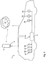
- a vehicle 1 which has a driver assistance system, by means of which the vehicle 1 from a start position S in a target position E, which is not visible from the vehicle 1, can be spent.
- the driver assistance system comprises a mobile terminal 5 and a control unit 3 of the vehicle 1.
- the control unit 3 communicates via a transmitting / receiving unit 7 wirelessly with the mobile terminal 5 and a satellite positioning system 11.
- the control unit 5 receives signals from the vehicle's own sensors, such as a speed sensor 35, a gyroscope 37, a magnetic field sensor 39 and at least one environmental sensor 41, for example an ultrasonic sensor, a radar sensor, a laser scanner or a camera.
- the control unit 3 issues control commands to a steering device or a braking device 31 or an engine control 33 of the vehicle 1.
- the mobile terminal 5 also communicates wirelessly with the satellite positioning service 11 via its transmitting / receiving unit 9.
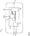
- a mobile terminal 5 which is designed as a smartphone and comprises a computing unit 13.
- the arithmetic unit 13 has a position calculation unit 15, to which a gyroscope 17 and a magnetic field sensor 19 of the mobile terminal 5 are connected in order to determine an alignment of the mobile terminal 5 in the global coordinate system KS.
- the gyroscope 17, which operates in all three spatial directions and the magnetic field sensor 19, which also takes into account all three spatial directions, and the orientation, comparable to a compass, in the earth's magnetic field, and acceleration sensors can be arranged in the mobile terminal 5, the accelerations of the Mobile terminal 5 also measure in all three directions.
- the yaw angle thus calculated in the position calculation unit 15 is supplied to a position determination unit 21, which additionally compensates this position with GPS position data or signals from location services 11, such as mobile radio or WLAN.
- location services 11 such as mobile radio or WLAN.
- the position determination in the mobile network or with respect to existing WLAN networks can also be carried out alternatively to the position calculation via the yaw angle.
- satellite-based positioning with GPS is also common.
- Both the yaw angle determined by the position calculation unit 15 and a path determined by the position determination unit 21 become in the global coordinate system KS issued to a driving maneuver planning device 23.
- a marked by the driver start position S and an end position E is further input, from which the mobile terminal 5 determines a plan for the driving maneuver of the vehicle 1 from the starting position S to the target position E, via the transmitting / receiving unit 9 at the control unit 3 of the vehicle 1 is output.
- the planned driving maneuver is only output from the mobile terminal 5 to the control unit 3 when the mobile terminal 5 has determined that the planned path for the driving maneuver is also feasible.
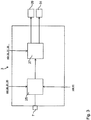
- the transceiver unit 7 of the control unit 3 receives the planned driving maneuver from the mobile terminal 5.
- the control unit 3 comprises a path planning unit 25 in which parameters emitted by the vehicle's own sensors 35, 37, 39, such as wheel speeds, the yaw rate and a magnetic field , are processed.
- data from environmental sensors 41 of the vehicle 1, such as ultrasound sensor, radar sensor, laser scanner or camera, can also be detected and forwarded to the path planning unit 25 of the control unit 3.
- a desired path of the vehicle 1 is calculated, which is to be moved from the start position S to the target position E.
- This target path of the vehicle 1 is output to a web control unit 27, which also receives from vehicle sensors 31, 33, 35 parameters such as wheel speeds, yaw angle and kink angle. In response to these parameters and the desired trajectory, the web control unit 27 outputs control signals in the form of a desired steering angle to a steering device 29 of the vehicle 1 and in the form of a target travel speed to a motor control 33 and / or brake 31.
- the starting position S of the vehicle 1 is located at the origin of the global coordinate system KS.
- this coordinate system KS the driving maneuver is planned and executed.
- the position of the mobile terminal 3 within the global coordinate system via the sensors of the mobile terminal 5.
- the position of the vehicle 15 in the global coordinate system KS via the vehicle sensors.
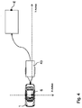
- Fig. 4 the motor vehicle 1 is shown with a trailer 43, which is to be moved to a parking lot, the target position E, so the parking lot, can not be detected by the vehicle's own sensors. Thus, the vehicle 1 is unable to determine the target position E of the trailer 43. With the help of the mobile terminal 5, for example, a smartphone, it is easy to bring the trailer 43 in the desired target position E. First, the driver takes place in the motor vehicle 1 on the driver's seat and marks the current position of the mobile terminal 5 as the starting position S for the driving maneuver. Alternatively, however, the starting position can also be detected by the control unit 3 of the vehicle 1.
- the driver gets off and runs to the desired target position E of the trailer 43. Also at this point, the driver marks the parking lot as the target position E for the driving maneuver on the mobile terminal 5. In addition, the orientation of the mobile terminal 1 at the destination position E set the orientation of the hanger 43 at the target position E.
- a maneuver of the vehicle 1 for suitable movement of the trailer 43 is planned in the maneuvering planning unit 23 of the mobile terminal 5, which is transmitted to the control unit 3 becomes.
- a desired path of the vehicle 1 is determined in the path planning unit 25, by means of which the trailer 43 is to be brought from the start position S to the end position E.
- the trajectory control unit 27 controls the autonomous drive of the vehicle 1 and corrects the desired trajectory based on the parameters of the explained vehicle sensors 35, 37, 39, 41 and control commands to the steering device 29 or the engine control 33 or the braking device 31 outputs.
- the movement of the trailer 43 relative to the vehicle 1 is detected with the aid of a kink angle sensor, not shown, which is preferably integrated in the ball head of the trailer device and sends signals to the control unit 3.
- a kink angle sensor not shown, which is preferably integrated in the ball head of the trailer device and sends signals to the control unit 3.
- the driver must continuously perform the circular movement on a touchscreen of the mobile terminal 5 in order to move the vehicle 1 from the start position S to the end position E. If the trailer 43 has arrived in its end position E, this is displayed to the driver on the mobile terminal 5.
- the different lanes which are predetermined corrected by the mobile terminal 5 but also by the control unit 3, can be displayed not only on the mobile terminal 3 but also on a display in the vehicle 1.
- the driver can select the preferred driving maneuver.
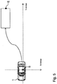
- FIG. 5 shows the described driving maneuver with a trailerless vehicle 1. Where also the starting point S for the driving maneuver in the vehicle 1 is located, which also forms the origin of the global coordinate system KS. After the driver has detected the starting position in the vehicle 1, he runs with the mobile terminal 5 to the target position E of the driving maneuver and detects this in place. The following signals are calculated in the mobile terminal 5 from the start position S to the end position E:
- three yaw angles are generated in the global coordinate system KS. These yaw angles describe the rotation of the mobile terminal 5 in the global coordinate system KS.
- the magnetic field sensor 19 can be used to assist the yaw rate calculation.
- the yaw angles are used to convert the three components of the acceleration sensor into the global coordinate system KS. By a two-fold integration of the three acceleration components in the global coordinate system KS, the path traveled by the driver can be recorded.
- GPS position data or position data of other positioning services 11 are used to support the route calculation in the position determination unit 21.
- the driver has reached the desired target position E, he confirms this on the mobile terminal 5, whereby this is marked. Subsequently, the driver on the mobile terminal 5 has the option to set the orientation of the vehicle 2 to the target position E by rotation of a schematic representation of the vehicle 1. If the driver agrees, the driving maneuver can begin by actuating the mobile terminal 5. During the driving maneuver, the driver can specify small course corrections via the mobile terminal 1 when the planned driving maneuver is being traveled by the vehicle 1, ie the driver can shift the vehicle 1 by a small offset about the planned path.
- different driving maneuvers can be planned with the mobile terminal 5 and displayed to the user for selection, for example, parking a normal vehicle or parking / parking with a trailer.
Description
Die Erfindung betrifft ein Verfahren zum Verbringen eines Fahrzeuges in eine Zielposition, wobei von einer Startposition des Fahrzeuges ausgegangen wird.The invention relates to a method for bringing a vehicle to a target position, starting from a starting position of the vehicle.
Aktuelle (semi-)automatische Parksysteme funktionieren nur, wenn sie die anzufahrende Parklücke zumindest teilweise mit einer On-Bord-Sensorik vermessen können. Dabei kann das Fahrzeug seine Position mit Hilfe von fahrzeugeigenen Sensoren in einer gelernten Umgebung feststellen und wird so in die Lage versetzt, eine bereits gefahrene Bahn wieder abzufahren. Allerdings kann eine vom Fahrzeug nicht erfassbare Zielposition nicht angefahren werden.Current (semi) automatic parking systems only work if they can at least partially measure the parking space to be approached with an on-board sensor system. In this case, the vehicle can determine its position with the aid of vehicle-mounted sensors in a learned environment and is thus enabled to drive off an already traveled lane again. However, a target position that can not be detected by the vehicle can not be approached.
Aus der
Die
Die Erfindung ergibt sich aus den Merkmalen der unabhängigen Ansprüche. Vorteilhafte Weiterbildungen und Ausgestaltungen sind Gegenstand der abhängigen Ansprüche. Weitere Merkmale, Anwendungsmöglichkeiten und Vorteile der Erfindung ergeben sich aus der nachfolgenden Beschreibung, sowie der Erläuterung von Ausführungsbeispielen der Erfindung, die in den Figuren dargestellt sind.
Die Aufgabe ist mit einem Verfahren dadurch gelöst, dass
- die Startposition von einem mobilen Endgerät oder dem Fahrzeug ermittelt wird,
- die Zielposition von dem mobilen Endgerät bestimmt wird,
- eine Fahrtrajektorie des Fahrzeuges innerhalb des Fahrzeuges geplant wird,
- ein Abfahren der Fahrtrajektorie des Fahrzeuges durch das Fahrzeug oder das mobile Endgerät initiiert wird.
The invention results from the features of the independent claims. Advantageous developments and refinements are the subject of the dependent claims. Other features, applications and advantages of the invention will become apparent from the following description, as well as the explanation of embodiments of the invention, which are illustrated in the figures.
The problem is solved by a method in that
- the starting position is determined by a mobile terminal or the vehicle,
- the destination position is determined by the mobile terminal,
- a driving trajectory of the vehicle is planned within the vehicle,
- a departure of the driving trajectory of the vehicle by the vehicle or the mobile terminal is initiated.
Dies hat den Vorteil, dass aufgrund der Verwendung des mobilen Endgerätes der Fahrer das vom Fahrzeug durchzuführende Fahrmanöver im Vorhinein abschreiten und die Ausrichtung des Fahrzeuges in der Zielposition festlegen kann. Ein weiterer Vorteil der Erfindung besteht darin, dass keine zusätzlichen Fahrzeugsensoren zur Planung des Fahrmanövers benötigt werden. Die Planung des Fahrmanövers ist für den Fahrer sehr einfach durchführbar. Das von dem mobilen Endgerät aufgezeichnete Fahrmanöver kann der Fahrer anschließend über eine Remote-Bedienung abfahren lassen. Dabei fährt das Fahrzeug autonom ohne Unterstützung des Fahrers.
Die Startposition kann auch durch den Fahrer festgelegt werden, indem er über eine Bedieneinrichtung auf dem mobilen Endgerät die Startposition festlegt. Ebenfalls kann die Startposition kann auch durch das Ereignis "Fahrer öffnet Fahrertür um Auszusteigen" oder "Fahrer legt P am Gangwahlhebel ein" festgelegt werden. Bei einer Aktivierung durch den Fahrer oder durch ein Ereignis ermittelt dann das Fahrzeug oder das mobile Endgerät die aktuelle Position des Fahrzeugs und setzt diese Position als Startposition des Parkvorgangs. Dies hat der Vorteil, dass der Fahrer die Möglichkeit hat ohne großen Aufwand die Startposition zu bestimmen. Die Bestimmung der Startposition kann flexibel und einfach erfolgen.
Vorteilhafterweise wird die Start- oder die Zielposition des Fahrzeuges über eine Ausrichtung des mobilen Endgerätes in einem globalen Koordinatensystem bestimmt. Durch die Verwendung dieses globalen Koordinatensystems lässt sich die Ziel- als auch die Startposition einfach auf das Fahrzeug übertragen und dort weiter verarbeiten.This has the advantage that due to the use of the mobile terminal, the driver can pre-empt the driving maneuver to be performed by the vehicle and can determine the orientation of the vehicle in the target position. Another advantage of the invention is that no additional vehicle sensors are needed to plan the driving maneuver. The planning of the driving maneuver is very easy for the driver to carry out. The driving maneuver recorded by the mobile terminal can then be left to the driver via a remote control. The vehicle drives autonomously without the assistance of the driver.
The starting position can also be determined by the driver by setting the starting position via an operating device on the mobile terminal. Also, the start position may also be determined by the event "driver opens driver door to exit" or "driver sets P on gear selector lever". When activated by the driver or by an event, the vehicle or mobile terminal then determines the current position of the vehicle and sets this position as the starting position of the parking process. This has the advantage that the driver has the opportunity without much effort to determine the starting position. The determination of the starting position can be flexible and easy.
Advantageously, the starting or the destination position of the vehicle is determined by an orientation of the mobile terminal in a global coordinate system. By using this global coordinate system, the target position as well as the starting position can be simply transferred to the vehicle and further processed there.
In der Erfindung erfolgt die Ausrichtung des mobilen Endgerätes in dem globalen Koordinatensystems mittels von dem mobilen Endgerät aufgenommenen Sensordaten, die an das Fahrzeug weitergeleitet werden. Über diese Ausrichtung des mobilen Endgerätes lässt sich einfach die Zielposition des Fahrzeuges darstellen, so dass diese für eine Planung eines Fahrmanövers einfach zu verwenden ist.In the invention, the alignment of the mobile terminal in the global coordinate system is performed by sensor data received from the mobile terminal and forwarded to the vehicle. This orientation of the mobile terminal makes it easy to represent the target position of the vehicle, so that it is easy to use for planning a driving maneuver.
In einer Variante wird das mobile Endgerät von der Startposition in die Zielposition verbracht, wobei das mobile Endgerät laufend Daten aufnimmt und für eine Fahrmanöverplanung auswertet. Aufgrund dieser laufend ermittelten Daten wird eine Fahrbahn charakterisiert, welche als Grundlage für ein Fahrmanöver des Fahrzeuges angesehen werden kann.In one variant, the mobile terminal is moved from the start position to the target position, wherein the mobile terminal continuously receives data and evaluates for a driving maneuver planning. On the basis of this continuously determined data, a roadway is characterized, which can be regarded as the basis for a driving maneuver of the vehicle.
In einer Ausführungsform werden über das mobile Endgerät während des Fahrmanövers des Fahrzeuges Kurskorrekturen des Fahrzeuges vorgenommen. Dadurch wird eine ständige Überwachung des Fahrmanövers des autonom fahrenden Fahrzeuges durch den Fahrer gewährleistet, wobei der Fahrer bei einer möglichen Kollision in das Fahrmanöver eingreifen kann.
Eine Weiterbildung der Erfindung betrifft eine Vorrichtung zum Verbringen eines Fahrzeuges in eine Zielposition, umfassend ein Steuergerät, welches mit einer Lenkeinrichtung und einer Motorsteuereinrichtung und/oder einer Bremseinrichtung des Fahrzeuges verbunden ist. Bei einer Vorrichtung, mit welcher das Fahrzeug eine von Sensoren nicht erfassbare Zielposition anfahren kann, ist
- ein mobiles Endgerät über eine drahtlose Kommunikationseinrichtung mit dem Steuergerät verbunden, welches eine Startposition oder eine Zielposition des Fahrzeuges ermittelt, und
- das Steuergerät eine Sollbahn auf der Grundlage des von dem mobilen Endgerät Erstellten Fahrmanöverplan bestimmt und die Sollbahn durch Ansteuerung der Lenkeinrichtung und der Motorsteuerung oder der Bremseinrichtung durchführt.
A development of the invention relates to a device for bringing a vehicle into a target position, comprising a control device which is connected to a steering device and a motor control device and / or a braking device of the vehicle. In a device with which the vehicle can approach a non-detectable by sensors target position is
- a mobile terminal connected via a wireless communication device to the controller, which determines a start position or a target position of the vehicle, and
- the controller sets a desired trajectory based on the one of the mobile terminal Determined driving maneuver determined and performs the desired path by driving the steering device and the engine control or braking device.
Aufgrund eines von dem mobilen Endgerät vorgeschlagenen Fahrmanövers kann die Vorrichtung eine wirkliche Fahrbahn, welche das Fahrzeug zum Einparken oder Einnehmen der nicht einsehbaren Zielposition abfahren soll, berechnen, auch ohne dass fahrzeugeigene Sensordaten ausgewertet werden müssen.On the basis of a driving maneuver proposed by the mobile terminal, the device can calculate a real roadway, which is to run the vehicle for parking or taking in the non-visible target position, even without having to evaluate the vehicle's own sensor data.
Vorteilhafterweise umfasst das Steuergerät eine Bahnregeleinrichtung, die mit einer Positionsbestimmungseinrichtung des Steuergerätes verbunden ist, welche eine Startposition des Fahrzeuges ermittelt. Durch die selbstständige Festlegung der Startposition des Fahrzeuges unabhängig von dem mobilen Endgerät wird die Genauigkeit der von dem Steuergerät ausgegebenen Sollbahn verbessert.Advantageously, the control device comprises a web control device, which is connected to a position determination device of the control device, which determines a start position of the vehicle. By independently setting the starting position of the vehicle independently of the mobile terminal, the accuracy of the output from the control unit nominal path is improved.
Eine weitere Weiterbildung der Erfindung betrifft ein Vorrichtung zur Fahrmanöverplanung eines Fahrzeuges, umfassend eine Recheneinheit. Bei einer solchen Vorrichtung, welche zur Steuerung einer nicht von fahrzeugeigenen Sensoren erfassbaren Zielposition geeignet ist, ist
- die Recheneinheit mit mindestens einem Positionserfassungssensor zur Bestimmung einer Startposition oder einer Zielposition oder einer möglichen Fahrbahn des Fahrzeuges verbunden,
- der mindestens eine Positionserfassungssensor an eine Positionsberechnungeinheit der Recheneinheit geführt ist, die die Position der Vorrichtung in einem globalen Koordinatensystem bestimmt und
- die Positionsberechnungseinheit und eine Positionsbestimmungseinheit mit einer Fahrmanöverplanungseinheit verbunden sind, welche das Fahrmanöver plant und
- die Recheneinheit mit einer Sende-/Empfangseinheit verknüpft ist, welche die Startposition oder die Zielposition oder das geplante Fahrmanöver an das Fahrzeug sendet.
- the computing unit is connected to at least one position detection sensor for determining a start position or a target position or a possible roadway of the vehicle,
- the at least one position detection sensor is guided to a position calculation unit of the arithmetic unit, which determines the position of the device in a global coordinate system, and
- the position calculation unit and a position determination unit are connected to a driving maneuver planning unit that plans the driving maneuver and
- the arithmetic unit is linked to a transmitting / receiving unit which transmits the starting position or the target position or the planned driving maneuver to the vehicle.
Mittels einer solchen mobilen Vorrichtung lässt sich unabhängig vom Fahrzeug eine mögliche Fahrtbahn des Fahrzeuges ermitteln. Es kann dann drahtlos an ein Steuergerät des Fahrzeuges übergeben werden, welches das vorgeschlagene Fahrmanöver mittels eigener Positionsdaten abgleichen kann und daraus eine Sollfahrbahn des Fahrzeuges ermittelt und ausführt.By means of such a mobile device, a possible trajectory of the vehicle can be determined independently of the vehicle. It can then be transferred wirelessly to a control unit of the vehicle, which can adjust the proposed driving maneuver by means of its own position data and from this determines and executes a desired driving lane of the vehicle.
Vorteilhafterweise ist die Positionsberechnungseinheit zur Berechnung eines Gier-Winkels mit einem Gyroskop oder einem Magnetfeldsensor oder einem Beschleunigungssensor verbunden, welche Sensordaten ausgeben, die alle drei Raumrichtungen umfassen. Mittels solcher in der mobilen Vorrichtung enthaltenen Positionssensoren lässt sich sehr genau eine dreidimensionale Positionierung der mobilen Vorrichtung sowohl in einer Startposition des Fahrzeuges als auch in einer möglichen Zielposition des Fahrzeuges angeben. Insbesondere durch die Ausrichtung der mobilen Vorrichtung in dem globalen Koordinatensystem lässt sich eindeutig die Zielposition dreidimensional ermitteln.Advantageously, the position calculation unit is for calculating a yaw angle connected to a gyroscope or a magnetic field sensor or an acceleration sensor, which outputs sensor data that includes all three spatial directions. By means of such position sensors contained in the mobile device, a three-dimensional positioning of the mobile device can be specified very precisely both in a start position of the vehicle and in a possible target position of the vehicle. In particular, by the orientation of the mobile device in the global coordinate system, the target position can be uniquely determined three-dimensionally.
In einer Variante ist die Positionsbestimmungseinheit mit einem drahtlosen Ortungssystem verbunden. Unter einem solchen drahtlosen Ortungssystem sollen dabei ein Mobilfunknetz oder ein WLAN-Netz oder satellitengestützte Systeme, wie beispielsweise GPS verstanden werden. Diese sind insbesondere dann von Vorteil, wenn auf zusätzliche Sensoren in der mobilen Vorrichtung verzichtet werden soll. Alternativ können die Daten der Ortungssysteme auch zum Abgleich der, durch die Sensoren der mobilen Vorrichtung bestimmten Daten verwendet werden.In one variant, the position determination unit is connected to a wireless location system. Such a wireless location system should be understood to mean a mobile radio network or a WLAN network or satellite-based systems, such as GPS. These are particularly advantageous if it is necessary to dispense with additional sensors in the mobile device. Alternatively, the location system data may also be used to balance the data determined by the mobile device sensors.
Weitere Vorteile, Merkmale und Einzelheiten ergeben sich aus der nachfolgenden Beschreibung, in der - gegebenenfalls unter Bezug auf die Zeichnung - zumindest ein Ausführungsbeispiel im Einzelnen beschrieben ist. Beschriebene oder bildlich dargestellte Merkmale können für sich oder in beliebiger, sinnvoller Kombination den Gegenstand der Erfindung bilden, gegebenenfalls auch unabhängig von den Ansprüchen, und können insbesondere zusätzlich auch Gegenstand einer oder mehrerer separater Anmeldung/en sein. Gleiche, ähnliche oder funktionsgleiche Teile sind mit gleichen Bezugszeichen versehen.Further advantages, features and details will become apparent from the following description in which - where appropriate, with reference to the drawings - at least one embodiment is described in detail. Described or illustrated features may form the subject of the invention itself or in any meaningful combination, optionally also independent of the claims, and in particular may additionally be the subject of one or more separate application / s. The same, similar or functionally identical parts are provided with the same reference numerals.
Es zeigen:
- Fig. 1
- ein Ausführungsbeispiel für ein Fahrzeug mit einem erfindungsgemäßen Fahrerassistenzsystem,
- Fig. 2
- ein Ausführungsbeispiel für ein erfindungsgemäßes mobiles Endgerät,
- Fig. 3
- ein Ausführungsbeispiel für eine erfindungsgemäße Vorrichtung zum autonomen Verbringen eines Fahrzeuges in eine Zielposition,
- Fig. 4
- ein Ausführungsbeispiel für eine Fahrmanöverplanung eines Kraftfahrzeuges mit einem Hänger,
- Fig. 5
- ein Beispiel für eine Fahrmanöverplanung eines hängerlosen Fahrzeuges.
- Fig. 1
- An exemplary embodiment of a vehicle with a driver assistance system according to the invention,
- Fig. 2
- an embodiment of a mobile terminal according to the invention,
- Fig. 3
- An embodiment of an inventive device for autonomous movement of a vehicle in a target position,
- Fig. 4
- an embodiment for a driving maneuver planning of a motor vehicle with a trailer,
- Fig. 5
- an example of a driving maneuver planning a trailerless vehicle.
In
In
Der so in der Positionsberechnungseinheit 15 berechnete Gierwinkel wird einer Positionsbestimmungseinheit 21 zugeführt, welche diese Position zusätzlich mit GPS-Positionsdaten oder Signalen aus Ortungsdiensten 11, wie Mobilfunk oder WLAN, abgleicht. Die Positionsbestimmung im Mobilfunknetz oder gegenüber vorhandenen WLAN-Netzen kann aber auch alternativ zu der Positionsberechnung über den Gierwinkel erfolgen. Üblich ist auch eine satellitengestützte Positionsbestimmung mit GPS.The yaw angle thus calculated in the
Sowohl der von der Positionsberechnungseinheit 15 bestimmte Gierwinkel als auch ein von der Positionsbestimmungseinheit 21 bestimmter Weg werden in dem globalen Koordinatensystem KS an eine Fahrmanöverplanungseinrichtung 23 ausgegeben. In diese Fahrmanöverplanungseinrichtung 23 wird weiterhin eine von dem Fahrer markierte Startposition S und eine Endposition E eingegeben, woraus das mobile Endgerät 5 einen Plan für das Fahrmanöver des Fahrzeuges 1 von der Startposition S zur Zielposition E bestimmt, der über die Sende- / Empfangseinheit 9 an das Steuergerät 3 des Fahrzeuges 1 ausgegeben wird.Both the yaw angle determined by the
Das geplante Fahrmanöver wird dabei nur dann von dem mobilen Endgerät 5 an das Steuergerät 3 ausgegeben, wenn das mobile Endgerät 5 festgestellt hat, dass die geplante Bahn für das Fahrmanöver auch durchführbar ist.The planned driving maneuver is only output from the
Wie in
Wie in
In
Erfasst der Fahrer die Startposition des Fahrmanövers auf dem Fahrersitz im Fahrzeug 1, müssen folgende Sensordaten erfasst werden:
- Ausrichtung des Fahrzeuges 1 im Erdmagnetfeld
- Ausrichtung des mobilen Endgerätes 5 im Erdmagnetfeld
- zusätzlich können Positionsdaten vom GPS oder einem anderen Ortungsdienst 11 genutzt werden.
- Alignment of the
vehicle 1 in the earth's magnetic field - Alignment of the
mobile terminal 5 in the earth's magnetic field - In addition, position data can be used by the GPS or another
location service 11.
Anschließend steigt der Fahrer aus und läuft an die gewünschte Zielposition E des Anhängers 43. Auch an dieser Stelle markiert der Fahrer den Parkplatz als Zielposition E für das Fahrmanöver auf dem mobilen Endgerät 5. Außerdem wird über die Ausrichtung des mobilen Endgerätes 1 an der Zielposition E die Ausrichtung des Hängers 43 an der Zielposition E festgelegt.Subsequently, the driver gets off and runs to the desired target position E of the
Aus dem Weg, welchen die Positionsbestimmungseinheit 21 des mobilen Endgerätes 5 von der Startposition S bis zur Endposition E aufzeichnet, wird in der Manöverplanungseinheit 23 des mobilen Endgerätes 5 ein Fahrmanöver des Fahrzeuges 1 zu geeigneten Verbringung des Hängers 43 geplant, welches an das Steuergerät 3 übertragen wird. In dem Steuergerät 3 wird eine Sollbahn des Fahrzeuges 1 in der Bahnplanungseinheit 25 bestimmt, mittels welcher der Anhänger 43 von der Startposition S in die Endposition E gebracht werden soll. Nach der Bestimmung der Sollbahn startet der Fahrer das Fahrmanöver über das mobile Endgerät 5, wobei die Bahnreglereinheit 27 die autonome Fahrt des Fahrzeuges 1 steuert und die Sollbahn anhand der Parameter der erläuterten fahrzeugeigenen Sensoren 35, 37, 39, 41 korrigiert und Steuerbefehle an die Lenkeinrichtung 29 oder die Motorsteuerung 33 oder die Bremseinrichtung 31 ausgibt. Die Bewegung des Anhängers 43 gegenüber dem Fahrzeug 1 wird mit der Hilfe eines nicht weiter dargestellten Knickwinkelsensors erfasst, welcher vorzugsweise im Kugelkopf der Anhängervorrichtung integriert ist und Signale an das Steuergerät 3 sendet. Dabei muss der Fahrer die Kreisbewegung auf einem Touchscreen des mobilen Endgerätes 5 fortlaufend durchführen, um das Fahrzeug 1 von der Startposition S bis zur Endposition E zu bewegen. Ist der Anhänger 43 in seiner Endposition E angekommen, wird dies dem Fahrer auf dem mobilen Endgerät 5 angezeigt.From the path which the
Die verschiedenen Fahrbahnen, welche durch das mobile Endgerät 5 aber auch durch das Steuergerät 3 korrigiert vorgegeben werden, lassen sich nicht bloß auf dem mobilen Endgerät 3 sondern auch auf einem Display im Fahrzeug 1 anzeigen. Der Fahrer kann dabei die von ihm favorisierte Fahrmanöverbahn auswählen.The different lanes, which are predetermined corrected by the
Diese Fahrmanöverplanung mit Hilfe des mobilen Endgerätes 5 ist nicht auf die Steuerung eines Gespanns aus Fahrzeug 5 und Anhänger 43 beschränkt, sondern kann auch als Erweiterung für automatisierte Parkfunktionen ohne Anhänger genutzt werden.
Durch Integration der drei Gierraten aus dem Gyroskop 17 des mobilen Endgerätes 5 werden drei Gierwinkel im globalen Koordinatensystem KS generiert. Diese Gierwinkel beschreiben die Drehung des mobilen Endgerätes 5 im globalen Koordinatensystem KS. Zusätzlich kann der Magnetfeldsensor 19 benutzt werden, um die Gierwinkel-Berechnung zu unterstützen. Die Gierwinkel werden dazu benutzt, die drei Komponenten des Beschleunigungssensors in das globale Koordinatensystem KS umzurechnen. Durch eine zweifache Integration der drei Beschleunigungskomponenten im globalen Koordinatensystem KS kann der vom Fahrer gelaufene Weg aufgezeichnet werden. Außerdem werden GPS-Positionsdaten bzw. Positionsdaten anderer Ortungsdienste 11 genutzt, um die Wegberechnung im der Positionsbestimmungseinheit 21 zu unterstützen.By integrating the three yaw rates from the
Hat der Fahrer die gewünschte Zielposition E erreicht, bestätigt er dies auf dem mobilen Endgerät 5, wodurch diese markiert wird. Anschließend hat der Fahrer auf dem mobilen Endgerät 5 die Möglichkeit, durch Drehung einer schematischen Darstellung des Fahrzeuges 1 die Ausrichtung des Fahrzeuges 2 an die Zielposition E festzulegen. Ist der Fahrer damit einverstanden, kann durch Betätigung des mobilen Endgerätes 5 das Fahrmanöver beginnen. Während des Fahrmanövers kann der Fahrer beim Abfahren des geplanten Fahrmanövers durch das Fahrzeug 1 kleine Kurskorrekturen über das mobile Endgerät 1 vorgeben, d.h. der Fahrer kann das Fahrzeug 1 um einen kleinen Versatz um die geplante Bahn verschieben.If the driver has reached the desired target position E, he confirms this on the
Wie beschrieben können mit dem mobilen Endgerät 5 verschiedene Fahrmanöver geplant und dem Benutzer zur Auswahl angezeigt werden, zum Beispiel ein Ein-/Ausparken eines normalen Fahrzeuges oder ein Ein-/Ausparken mit Hänger.As described, different driving maneuvers can be planned with the
Obwohl die Erfindung im Detail durch bevorzugte Ausführungsbeispiele näher illustriert und erläutert wurde, so ist die Erfindung nicht durch die offenbarten Beispiele eingeschränkt und andere Variationen können vom Fachmann hieraus abgeleitet werden, ohne den Schutzumfang der Erfindung zu verlassen. Es ist daher klar, dass eine Vielzahl von Variationsmöglichkeiten existiert. Es ist ebenfalls klar, dass beispielhaft genannte Ausführungsformen wirklich nur Beispiele darstellen, die nicht in irgendeiner Weise als Begrenzung etwa des Schutzbereichs, der Anwendungsmöglichkeiten oder der Konfiguration der Erfindung aufzufassen sind. Vielmehr versetzen die vorhergehende Beschreibung und die Figurenbeschreibung den Fachmann in die Lage, die beispielhaften Ausführungsformen konkret umzusetzen, wobei der Fachmann in Kenntnis des offenbarten Erfindungsgedankens vielfältige Änderungen beispielsweise hinsichtlich der Funktion oder der Anordnung einzelner, in einer beispielhaften Ausführungsform genannter Elemente vornehmen kann, ohne den Schutzbereich zu verlassen, der durch die Ansprüche und deren rechtliche Entsprechungen, wie etwa weitergehenden Erläuterungen in der Beschreibung, definiert sind.Although the invention has been further illustrated and explained in detail by way of preferred embodiments, the invention is not limited by the disclosed examples, and other variations can be derived therefrom by those skilled in the art without departing from the scope of the invention. It is therefore clear that a multitude of possible variations exists. It is also to be understood that exemplified embodiments are really only examples that are not to be construed in any way as limiting the scope, applicability, or configuration of the invention. Rather, the foregoing description and description of the figures enable one skilled in the art to practice the exemplary embodiments, and those of skill in the knowledge of the disclosed inventive concept may make various changes, for example as to the function or arrangement of particular elements recited in an exemplary embodiment, without Protection area defined by the claims and their legal equivalents, such as further explanations in the description.
Claims (7)
- Method for conducting a vehicle (1) from a starting position (S) to a target position (E) along a set path determined in the vehicle (1), wherein the travelling of the set path is initiated by the vehicle (1) or by a mobile terminal device (5) and wherein the starting position (S) is determined by a mobile terminal device (5) or by the vehicle (1) and the target position (E) is determined by the mobile terminal device (5),
characterised in that
the orientation of the vehicle (1) in the target position is defined by way of an orientation of the mobile terminal device (5) in a global coordinate system (KS). - Method according to claim 1,
characterised in that
the determination of the starting or target position (S, E) of the vehicle (1) is activated by an event and the starting or target position (S, E) is determined by way of an orientation of the mobile terminal device (5) in a global coordinate system (KS). - Method according to claims 1 and 2,
characterised in that
the orientation of the mobile terminal device (5) in the global coordinate system (KS) is determined by means of sensor data recorded by the mobile terminal device (5) and transferred to the motor vehicle (25). - Method according to claim 3,
characterised in that
the mobile terminal device (5) is conducted from the starting position (S) to the target position (E), the mobile terminal device (5) continuously recording data and evaluating them for driving manoeuvre planning. - Method according to one or more of the preceding claims,
characterised in that
course corrections of the vehicle (1) are performed by way of the mobile terminal device (5) during the driving manoeuvre of the vehicle (1). - Device for conducting a vehicle (1) from a starting position (S) to a target position (E), the device comprising a control unit (3) connected to a steering device (29) and an engine control unit (33) or a braking device (31) of the vehicle (1), wherein
a mobile terminal device (5) is connected to the control unit (3), which determines the starting position (S) or the target position (E) of the vehicle (1), via a wireless communication device (7, 9), and wherein the control unit (3) determines a set path on the basis of a driving manoeuvre plan provided by the mobile terminal device (5) and travels the set path by activating the steering device (29) and the engine control unit (33) or the braking device (31),
characterised in that
the orientation of the vehicle (1) in the target position is defined by way of an orientation of the mobile terminal device (5) in a global coordinate system (KS). - Device according to claim 6,
characterised in that
the control unit (3) comprises a path controller unit (25), which is connected to a position detecting device of the control unit (3), which position detecting device detects a starting position (S) of the vehicle (1).
Applications Claiming Priority (2)
| Application Number | Priority Date | Filing Date | Title |
|---|---|---|---|
| DE102014011796.0A DE102014011796A1 (en) | 2014-08-08 | 2014-08-08 | Method and device for moving a vehicle to a destination position |
| PCT/EP2015/001289 WO2016020024A1 (en) | 2014-08-08 | 2015-06-26 | Method and device for moving a vehicle into a target position |
Publications (2)
| Publication Number | Publication Date |
|---|---|
| EP3177503A1 EP3177503A1 (en) | 2017-06-14 |
| EP3177503B1 true EP3177503B1 (en) | 2018-10-10 |
Family
ID=53524717
Family Applications (1)
| Application Number | Title | Priority Date | Filing Date |
|---|---|---|---|
| EP15734571.1A Active EP3177503B1 (en) | 2014-08-08 | 2015-06-26 | Method and apparatus to conduct a vehicle to a target position |
Country Status (6)
| Country | Link |
|---|---|
| US (1) | US10179585B2 (en) |
| EP (1) | EP3177503B1 (en) |
| JP (1) | JP6452801B2 (en) |
| CN (1) | CN106660584B (en) |
| DE (1) | DE102014011796A1 (en) |
| WO (1) | WO2016020024A1 (en) |
Families Citing this family (16)
| Publication number | Priority date | Publication date | Assignee | Title |
|---|---|---|---|---|
| US9926008B2 (en) * | 2011-04-19 | 2018-03-27 | Ford Global Technologies, Llc | Trailer backup assist system with waypoint selection |
| DE102014019487A1 (en) | 2014-12-23 | 2016-06-23 | Daimler Ag | Method and device for locating a mobile unit in a vehicle |
| CN107444264A (en) * | 2016-05-31 | 2017-12-08 | 法拉第未来公司 | Use the object of camera calibration du vehicule |
| DE102016116857A1 (en) | 2016-09-08 | 2018-03-08 | Knorr-Bremse Systeme für Nutzfahrzeuge GmbH | System and method for operating commercial vehicles |
| DE102016116860A1 (en) | 2016-09-08 | 2018-03-08 | Knorr-Bremse Systeme für Nutzfahrzeuge GmbH | System and method for operating autonomously driving commercial vehicles |
| DE102016226008A1 (en) | 2016-12-22 | 2018-06-28 | Bayerische Motoren Werke Aktiengesellschaft | Remote control of a vehicle function of a motor vehicle by means of a touch gesture on the remote control |
| CN106970629B (en) * | 2017-05-22 | 2020-03-03 | 北京京东尚科信息技术有限公司 | Control method and device for automated guided vehicle |
| CA3072034C (en) * | 2017-08-10 | 2023-06-20 | Nissan Motor Co., Ltd. | Parking control method and parking control device |
| CN108563219B (en) * | 2017-12-29 | 2021-07-13 | 青岛海通机器人系统有限公司 | AGV avoidance method |
| US10705529B2 (en) | 2018-01-05 | 2020-07-07 | Honda Motor Co., Ltd. | Autonomous all-terrain vehicle (ATV) |
| JP6897597B2 (en) * | 2018-02-16 | 2021-06-30 | トヨタ自動車株式会社 | Parking support device |
| JP7032950B2 (en) * | 2018-02-19 | 2022-03-09 | 株式会社デンソーテン | Vehicle remote control device, vehicle remote control system and vehicle remote control method |
| US10976733B2 (en) | 2018-09-26 | 2021-04-13 | Ford Global Technologies, Llc | Interfaces for remote trailer maneuver assist |
| DE102019201186A1 (en) * | 2019-01-30 | 2020-07-30 | Continental Teves Ag & Co. Ohg | Ultrasound system and a method for locating a driver |
| CN112428981B (en) * | 2019-08-20 | 2022-05-24 | 北京图森智途科技有限公司 | Control method and device for automatically driving truck and automatically driving truck |
| CN114001745B (en) * | 2021-10-25 | 2023-11-24 | 东南大学 | Electric automobile parking guide system and position detection and evaluation method thereof |
Family Cites Families (16)
| Publication number | Priority date | Publication date | Assignee | Title |
|---|---|---|---|---|
| DE10117650A1 (en) | 2001-04-09 | 2002-10-10 | Daimler Chrysler Ag | Bringing vehicle to target position, involves outputting control commands to drive train, braking system and/or steering so vehicle can be steered to target position independently of driver |
| JP4052198B2 (en) | 2003-07-25 | 2008-02-27 | 株式会社デンソー | Vehicle guidance device and route determination program |
| JP2008009913A (en) | 2006-06-30 | 2008-01-17 | Toyota Motor Corp | Automatic vehicle driving system |
| JP5115782B2 (en) * | 2006-11-07 | 2013-01-09 | アイシン精機株式会社 | Parking assistance device |
| US8682576B2 (en) * | 2008-12-04 | 2014-03-25 | Verizon Patent And Licensing Inc. | Navigation based on user-defined points and paths |
| JP5004031B2 (en) | 2008-12-09 | 2012-08-22 | 株式会社安川電機 | MOBILE BODY CONTROL METHOD, CONTROL DEVICE, AND MOBILE BODY SYSTEM |
| KR101453172B1 (en) * | 2010-04-12 | 2014-10-27 | 도요타 지도샤(주) | Vehicle remote operation system and on-board device |
| US8793036B2 (en) * | 2010-09-22 | 2014-07-29 | The Boeing Company | Trackless transit system with adaptive vehicles |
| KR20120086140A (en) * | 2011-01-25 | 2012-08-02 | 한국전자통신연구원 | Mobile and apparatus for providing auto valet parking service and method thereof |
| JP5729176B2 (en) | 2011-07-01 | 2015-06-03 | アイシン・エィ・ダブリュ株式会社 | Movement guidance system, movement guidance apparatus, movement guidance method, and computer program |
| DE102012200725A1 (en) | 2012-01-19 | 2013-07-25 | Robert Bosch Gmbh | Remote control of parking and maneuvering maneuvers of motor vehicles |
| JP2014065392A (en) | 2012-09-25 | 2014-04-17 | Aisin Seiki Co Ltd | Portable terminal, remote control system, remote control method, and program |
| DE102012022087A1 (en) | 2012-11-09 | 2014-05-15 | Volkswagen Aktiengesellschaft | Method for controlling parking operation of car, involves determining position of vehicle associated with and located outside of vehicle, and controlling parking operation in response to evaluation of position of reference device |
| KR102027917B1 (en) * | 2013-08-07 | 2019-10-02 | 현대모비스 주식회사 | Smartkey System using movement pattern recognition of a mobile device and operation method thereof |
| DE102013015349A1 (en) | 2013-09-17 | 2014-04-10 | Daimler Ag | Method for starting-up of vehicle for parking in parking lot, involves determining whether vehicle is to be parked in home parking lot or home parking zone when starting-up vehicle, based on identified environmental data of vehicle |
| DE102013016342A1 (en) * | 2013-09-30 | 2015-04-02 | Daimler Ag | Method for assisting reversing a team, driver assistance system |
-
2014
- 2014-08-08 DE DE102014011796.0A patent/DE102014011796A1/en not_active Withdrawn
-
2015
- 2015-06-26 EP EP15734571.1A patent/EP3177503B1/en active Active
- 2015-06-26 WO PCT/EP2015/001289 patent/WO2016020024A1/en active Application Filing
- 2015-06-26 JP JP2017505146A patent/JP6452801B2/en active Active
- 2015-06-26 US US15/502,292 patent/US10179585B2/en active Active
- 2015-06-26 CN CN201580042522.0A patent/CN106660584B/en active Active
Non-Patent Citations (1)
| Title |
|---|
| None * |
Also Published As
| Publication number | Publication date |
|---|---|
| JP6452801B2 (en) | 2019-01-16 |
| EP3177503A1 (en) | 2017-06-14 |
| DE102014011796A1 (en) | 2016-02-11 |
| CN106660584A (en) | 2017-05-10 |
| WO2016020024A1 (en) | 2016-02-11 |
| US10179585B2 (en) | 2019-01-15 |
| JP2017524594A (en) | 2017-08-31 |
| US20170225679A1 (en) | 2017-08-10 |
| CN106660584B (en) | 2020-09-11 |
Similar Documents
| Publication | Publication Date | Title |
|---|---|---|
| EP3177503B1 (en) | Method and apparatus to conduct a vehicle to a target position | |
| EP3268826B1 (en) | Guiding of a motor vehicle in a parking lot | |
| EP3177504B1 (en) | Method for the at least semi-autonomous manoeuvring of a motor vehicle, driver assistance system and motor vehicle | |
| EP3224118B1 (en) | Method and device for assisted driving of a vehicle | |
| EP3401190B1 (en) | Method for operating a driver assistance system of a motor vehicle in order to manoeuvre the motor vehicle in a drivable area, driver assistance system and motor vehicle | |
| EP3224117B1 (en) | Method and device for assisted guiding of a vehicle | |
| EP3095676B1 (en) | Method for user-defined provision of a vehicle | |
| DE102013019771A1 (en) | Method for positioning a motor vehicle in an automated parking operation and a motor vehicle with a driver assistance system | |
| DE102015001631B4 (en) | Method for operating a motor vehicle in a navigation environment and navigation environment | |
| WO2014029492A1 (en) | Method for controlling an autonomous vehicle system and motor vehicle | |
| DE102016218876B4 (en) | Method for operating a motor vehicle, motor vehicle and method for determining setpoint trajectory information | |
| EP3565756B1 (en) | Control unit and method for determining a trajectory for a reversing assistance system | |
| EP3333049A1 (en) | Method for autonomous manoeuvring of a motor vehicle on a parking lot by determining a vehicle path using a digital map, infrastructure device, vehicle driver assistance systems, motor vehicle and communication systems | |
| DE102014216577A1 (en) | Method and device for assisting a driver of a motor vehicle | |
| DE102012023498A1 (en) | Method for guiding automatic and/or assistive vehicle i.e. motor car, involves transmitting stored information to vehicle to decide whether track portion is suitable to guide automatic and/or assisting vehicle by environment sensor system | |
| DE102014013219A1 (en) | Assistance system for maneuvering a team and method for operating such an assistance system | |
| WO2018099740A1 (en) | Method for autonomously maneuvering a motor vehicle on a parking surface with a step of determining a position deviation, infrastructure device, driver assistance systems, motor vehicle, and communication system | |
| WO2018086835A1 (en) | Method for manoeuvring a motor vehicle taking into account position values determined in a recording phase, driver assistance system and motor vehicle | |
| DE102020107941A1 (en) | Method for providing different driver assistance functions for a vehicle for the automated driving of previously recorded routes, computing device and driver assistance device | |
| DE102013212708B4 (en) | Method and device for carrying out autonomous driving maneuvers of a vehicle | |
| EP2975593A1 (en) | Method for supporting a driver when parking of a motor vehicle, driver assistance system and motor vehicle | |
| DE102015202469A1 (en) | Method and device for reducing a risk of collision between two vehicles driving in a parking lot | |
| EP3395652B1 (en) | Driving assist system for a vehicle with an assistant for driving out of a parking space and a slow travel assistant | |
| EP2982564B1 (en) | Method for supporting a driver when parking of a motor vehicle, driver assistance system and motor vehicle | |
| EP3584142A1 (en) | Method for determining a target trajectory for carrying out a shunting process with a vehicle set |
Legal Events
| Date | Code | Title | Description |
|---|---|---|---|
| STAA | Information on the status of an ep patent application or granted ep patent |
Free format text: STATUS: THE INTERNATIONAL PUBLICATION HAS BEEN MADE |
|
| PUAI | Public reference made under article 153(3) epc to a published international application that has entered the european phase |
Free format text: ORIGINAL CODE: 0009012 |
|
| STAA | Information on the status of an ep patent application or granted ep patent |
Free format text: STATUS: REQUEST FOR EXAMINATION WAS MADE |
|
| 17P | Request for examination filed |
Effective date: 20170206 |
|
| AK | Designated contracting states |
Kind code of ref document: A1 Designated state(s): AL AT BE BG CH CY CZ DE DK EE ES FI FR GB GR HR HU IE IS IT LI LT LU LV MC MK MT NL NO PL PT RO RS SE SI SK SM TR |
|
| AX | Request for extension of the european patent |
Extension state: BA ME |
|
| DAV | Request for validation of the european patent (deleted) | ||
| DAX | Request for extension of the european patent (deleted) | ||
| GRAP | Despatch of communication of intention to grant a patent |
Free format text: ORIGINAL CODE: EPIDOSNIGR1 |
|
| STAA | Information on the status of an ep patent application or granted ep patent |
Free format text: STATUS: GRANT OF PATENT IS INTENDED |
|
| INTG | Intention to grant announced |
Effective date: 20180426 |
|
| GRAS | Grant fee paid |
Free format text: ORIGINAL CODE: EPIDOSNIGR3 |
|
| GRAA | (expected) grant |
Free format text: ORIGINAL CODE: 0009210 |
|
| STAA | Information on the status of an ep patent application or granted ep patent |
Free format text: STATUS: THE PATENT HAS BEEN GRANTED |
|
| AK | Designated contracting states |
Kind code of ref document: B1 Designated state(s): AL AT BE BG CH CY CZ DE DK EE ES FI FR GB GR HR HU IE IS IT LI LT LU LV MC MK MT NL NO PL PT RO RS SE SI SK SM TR |
|
| REG | Reference to a national code |
Ref country code: GB Ref legal event code: FG4D Free format text: NOT ENGLISH |
|
| REG | Reference to a national code |
Ref country code: CH Ref legal event code: EP Ref country code: AT Ref legal event code: REF Ref document number: 1050884 Country of ref document: AT Kind code of ref document: T Effective date: 20181015 |
|
| REG | Reference to a national code |
Ref country code: DE Ref legal event code: R096 Ref document number: 502015006344 Country of ref document: DE Ref country code: IE Ref legal event code: FG4D Free format text: LANGUAGE OF EP DOCUMENT: GERMAN |
|
| REG | Reference to a national code |
Ref country code: NL Ref legal event code: MP Effective date: 20181010 |
|
| REG | Reference to a national code |
Ref country code: LT Ref legal event code: MG4D |
|
| PG25 | Lapsed in a contracting state [announced via postgrant information from national office to epo] |
Ref country code: NL Free format text: LAPSE BECAUSE OF FAILURE TO SUBMIT A TRANSLATION OF THE DESCRIPTION OR TO PAY THE FEE WITHIN THE PRESCRIBED TIME-LIMIT Effective date: 20181010 |
|
| PG25 | Lapsed in a contracting state [announced via postgrant information from national office to epo] |
Ref country code: ES Free format text: LAPSE BECAUSE OF FAILURE TO SUBMIT A TRANSLATION OF THE DESCRIPTION OR TO PAY THE FEE WITHIN THE PRESCRIBED TIME-LIMIT Effective date: 20181010 Ref country code: PL Free format text: LAPSE BECAUSE OF FAILURE TO SUBMIT A TRANSLATION OF THE DESCRIPTION OR TO PAY THE FEE WITHIN THE PRESCRIBED TIME-LIMIT Effective date: 20181010 Ref country code: HR Free format text: LAPSE BECAUSE OF FAILURE TO SUBMIT A TRANSLATION OF THE DESCRIPTION OR TO PAY THE FEE WITHIN THE PRESCRIBED TIME-LIMIT Effective date: 20181010 Ref country code: LV Free format text: LAPSE BECAUSE OF FAILURE TO SUBMIT A TRANSLATION OF THE DESCRIPTION OR TO PAY THE FEE WITHIN THE PRESCRIBED TIME-LIMIT Effective date: 20181010 Ref country code: IS Free format text: LAPSE BECAUSE OF FAILURE TO SUBMIT A TRANSLATION OF THE DESCRIPTION OR TO PAY THE FEE WITHIN THE PRESCRIBED TIME-LIMIT Effective date: 20190210 Ref country code: FI Free format text: LAPSE BECAUSE OF FAILURE TO SUBMIT A TRANSLATION OF THE DESCRIPTION OR TO PAY THE FEE WITHIN THE PRESCRIBED TIME-LIMIT Effective date: 20181010 Ref country code: BG Free format text: LAPSE BECAUSE OF FAILURE TO SUBMIT A TRANSLATION OF THE DESCRIPTION OR TO PAY THE FEE WITHIN THE PRESCRIBED TIME-LIMIT Effective date: 20190110 Ref country code: LT Free format text: LAPSE BECAUSE OF FAILURE TO SUBMIT A TRANSLATION OF THE DESCRIPTION OR TO PAY THE FEE WITHIN THE PRESCRIBED TIME-LIMIT Effective date: 20181010 Ref country code: NO Free format text: LAPSE BECAUSE OF FAILURE TO SUBMIT A TRANSLATION OF THE DESCRIPTION OR TO PAY THE FEE WITHIN THE PRESCRIBED TIME-LIMIT Effective date: 20190110 |
|
| PG25 | Lapsed in a contracting state [announced via postgrant information from national office to epo] |
Ref country code: RS Free format text: LAPSE BECAUSE OF FAILURE TO SUBMIT A TRANSLATION OF THE DESCRIPTION OR TO PAY THE FEE WITHIN THE PRESCRIBED TIME-LIMIT Effective date: 20181010 Ref country code: GR Free format text: LAPSE BECAUSE OF FAILURE TO SUBMIT A TRANSLATION OF THE DESCRIPTION OR TO PAY THE FEE WITHIN THE PRESCRIBED TIME-LIMIT Effective date: 20190111 Ref country code: PT Free format text: LAPSE BECAUSE OF FAILURE TO SUBMIT A TRANSLATION OF THE DESCRIPTION OR TO PAY THE FEE WITHIN THE PRESCRIBED TIME-LIMIT Effective date: 20190210 Ref country code: AL Free format text: LAPSE BECAUSE OF FAILURE TO SUBMIT A TRANSLATION OF THE DESCRIPTION OR TO PAY THE FEE WITHIN THE PRESCRIBED TIME-LIMIT Effective date: 20181010 Ref country code: SE Free format text: LAPSE BECAUSE OF FAILURE TO SUBMIT A TRANSLATION OF THE DESCRIPTION OR TO PAY THE FEE WITHIN THE PRESCRIBED TIME-LIMIT Effective date: 20181010 |
|
| REG | Reference to a national code |
Ref country code: DE Ref legal event code: R097 Ref document number: 502015006344 Country of ref document: DE |
|
| PG25 | Lapsed in a contracting state [announced via postgrant information from national office to epo] |
Ref country code: DK Free format text: LAPSE BECAUSE OF FAILURE TO SUBMIT A TRANSLATION OF THE DESCRIPTION OR TO PAY THE FEE WITHIN THE PRESCRIBED TIME-LIMIT Effective date: 20181010 Ref country code: CZ Free format text: LAPSE BECAUSE OF FAILURE TO SUBMIT A TRANSLATION OF THE DESCRIPTION OR TO PAY THE FEE WITHIN THE PRESCRIBED TIME-LIMIT Effective date: 20181010 Ref country code: IT Free format text: LAPSE BECAUSE OF FAILURE TO SUBMIT A TRANSLATION OF THE DESCRIPTION OR TO PAY THE FEE WITHIN THE PRESCRIBED TIME-LIMIT Effective date: 20181010 |
|
| PLBE | No opposition filed within time limit |
Free format text: ORIGINAL CODE: 0009261 |
|
| STAA | Information on the status of an ep patent application or granted ep patent |
Free format text: STATUS: NO OPPOSITION FILED WITHIN TIME LIMIT |
|
| PG25 | Lapsed in a contracting state [announced via postgrant information from national office to epo] |
Ref country code: RO Free format text: LAPSE BECAUSE OF FAILURE TO SUBMIT A TRANSLATION OF THE DESCRIPTION OR TO PAY THE FEE WITHIN THE PRESCRIBED TIME-LIMIT Effective date: 20181010 Ref country code: SK Free format text: LAPSE BECAUSE OF FAILURE TO SUBMIT A TRANSLATION OF THE DESCRIPTION OR TO PAY THE FEE WITHIN THE PRESCRIBED TIME-LIMIT Effective date: 20181010 Ref country code: SM Free format text: LAPSE BECAUSE OF FAILURE TO SUBMIT A TRANSLATION OF THE DESCRIPTION OR TO PAY THE FEE WITHIN THE PRESCRIBED TIME-LIMIT Effective date: 20181010 Ref country code: EE Free format text: LAPSE BECAUSE OF FAILURE TO SUBMIT A TRANSLATION OF THE DESCRIPTION OR TO PAY THE FEE WITHIN THE PRESCRIBED TIME-LIMIT Effective date: 20181010 |
|
| 26N | No opposition filed |
Effective date: 20190711 |
|
| PG25 | Lapsed in a contracting state [announced via postgrant information from national office to epo] |
Ref country code: SI Free format text: LAPSE BECAUSE OF FAILURE TO SUBMIT A TRANSLATION OF THE DESCRIPTION OR TO PAY THE FEE WITHIN THE PRESCRIBED TIME-LIMIT Effective date: 20181010 |
|
| PG25 | Lapsed in a contracting state [announced via postgrant information from national office to epo] |
Ref country code: MC Free format text: LAPSE BECAUSE OF FAILURE TO SUBMIT A TRANSLATION OF THE DESCRIPTION OR TO PAY THE FEE WITHIN THE PRESCRIBED TIME-LIMIT Effective date: 20181010 |
|
| REG | Reference to a national code |
Ref country code: CH Ref legal event code: PL |
|
| REG | Reference to a national code |
Ref country code: BE Ref legal event code: MM Effective date: 20190630 |
|
| PG25 | Lapsed in a contracting state [announced via postgrant information from national office to epo] |
Ref country code: TR Free format text: LAPSE BECAUSE OF FAILURE TO SUBMIT A TRANSLATION OF THE DESCRIPTION OR TO PAY THE FEE WITHIN THE PRESCRIBED TIME-LIMIT Effective date: 20181010 |
|
| PG25 | Lapsed in a contracting state [announced via postgrant information from national office to epo] |
Ref country code: IE Free format text: LAPSE BECAUSE OF NON-PAYMENT OF DUE FEES Effective date: 20190626 |
|
| PG25 | Lapsed in a contracting state [announced via postgrant information from national office to epo] |
Ref country code: CH Free format text: LAPSE BECAUSE OF NON-PAYMENT OF DUE FEES Effective date: 20190630 Ref country code: LI Free format text: LAPSE BECAUSE OF NON-PAYMENT OF DUE FEES Effective date: 20190630 Ref country code: BE Free format text: LAPSE BECAUSE OF NON-PAYMENT OF DUE FEES Effective date: 20190630 Ref country code: LU Free format text: LAPSE BECAUSE OF NON-PAYMENT OF DUE FEES Effective date: 20190626 |
|
| REG | Reference to a national code |
Ref country code: DE Ref legal event code: R081 Ref document number: 502015006344 Country of ref document: DE Owner name: MERCEDES-BENZ GROUP AG, DE Free format text: FORMER OWNER: DAIMLER AG, 70327 STUTTGART, DE Ref country code: DE Ref legal event code: R082 Ref document number: 502015006344 Country of ref document: DE Representative=s name: JENSEN & SON, GB Ref country code: DE Ref legal event code: R081 Ref document number: 502015006344 Country of ref document: DE Owner name: DAIMLER AG, DE Free format text: FORMER OWNER: DAIMLER AG, 70327 STUTTGART, DE Ref country code: DE Ref legal event code: R082 Ref document number: 502015006344 Country of ref document: DE Representative=s name: JENSENS IP LIMITED, IE |
|
| REG | Reference to a national code |
Ref country code: DE Ref legal event code: R082 Ref document number: 502015006344 Country of ref document: DE Representative=s name: JENSENS IP LIMITED, IE |
|
| PG25 | Lapsed in a contracting state [announced via postgrant information from national office to epo] |
Ref country code: CY Free format text: LAPSE BECAUSE OF FAILURE TO SUBMIT A TRANSLATION OF THE DESCRIPTION OR TO PAY THE FEE WITHIN THE PRESCRIBED TIME-LIMIT Effective date: 20181010 |
|
| PG25 | Lapsed in a contracting state [announced via postgrant information from national office to epo] |
Ref country code: HU Free format text: LAPSE BECAUSE OF FAILURE TO SUBMIT A TRANSLATION OF THE DESCRIPTION OR TO PAY THE FEE WITHIN THE PRESCRIBED TIME-LIMIT; INVALID AB INITIO Effective date: 20150626 Ref country code: MT Free format text: LAPSE BECAUSE OF FAILURE TO SUBMIT A TRANSLATION OF THE DESCRIPTION OR TO PAY THE FEE WITHIN THE PRESCRIBED TIME-LIMIT Effective date: 20181010 |
|
| REG | Reference to a national code |
Ref country code: AT Ref legal event code: MM01 Ref document number: 1050884 Country of ref document: AT Kind code of ref document: T Effective date: 20200626 |
|
| PG25 | Lapsed in a contracting state [announced via postgrant information from national office to epo] |
Ref country code: AT Free format text: LAPSE BECAUSE OF NON-PAYMENT OF DUE FEES Effective date: 20200626 |
|
| REG | Reference to a national code |
Ref country code: DE Ref legal event code: R081 Ref document number: 502015006344 Country of ref document: DE Owner name: MERCEDES-BENZ GROUP AG, DE Free format text: FORMER OWNER: DAIMLER AG, STUTTGART, DE Ref country code: DE Ref legal event code: R082 Ref document number: 502015006344 Country of ref document: DE |
|
| PG25 | Lapsed in a contracting state [announced via postgrant information from national office to epo] |
Ref country code: MK Free format text: LAPSE BECAUSE OF FAILURE TO SUBMIT A TRANSLATION OF THE DESCRIPTION OR TO PAY THE FEE WITHIN THE PRESCRIBED TIME-LIMIT Effective date: 20181010 |
|
| PGFP | Annual fee paid to national office [announced via postgrant information from national office to epo] |
Ref country code: FR Payment date: 20230622 Year of fee payment: 9 Ref country code: DE Payment date: 20230627 Year of fee payment: 9 |
|
| PGFP | Annual fee paid to national office [announced via postgrant information from national office to epo] |
Ref country code: GB Payment date: 20230620 Year of fee payment: 9 |