JP6452801B2 - Method and apparatus for moving a car to a target position - Google Patents
Method and apparatus for moving a car to a target position Download PDFInfo
- Publication number
- JP6452801B2 JP6452801B2 JP2017505146A JP2017505146A JP6452801B2 JP 6452801 B2 JP6452801 B2 JP 6452801B2 JP 2017505146 A JP2017505146 A JP 2017505146A JP 2017505146 A JP2017505146 A JP 2017505146A JP 6452801 B2 JP6452801 B2 JP 6452801B2
- Authority
- JP
- Japan
- Prior art keywords
- mobile terminal
- target position
- car
- calculation unit
- determined
- Prior art date
- Legal status (The legal status is an assumption and is not a legal conclusion. Google has not performed a legal analysis and makes no representation as to the accuracy of the status listed.)
- Active
Links
- 238000000034 method Methods 0.000 title claims description 17
- 230000001133 acceleration Effects 0.000 claims description 6
- 230000005540 biological transmission Effects 0.000 claims description 6
- 238000001514 detection method Methods 0.000 claims description 4
- 238000004891 communication Methods 0.000 claims description 2
- 230000001960 triggered effect Effects 0.000 claims 1
- 230000008901 benefit Effects 0.000 description 5
- 238000013459 approach Methods 0.000 description 3
- 238000012937 correction Methods 0.000 description 3
- 238000011161 development Methods 0.000 description 3
- 230000018109 developmental process Effects 0.000 description 3
- 238000010295 mobile communication Methods 0.000 description 3
- 230000002093 peripheral effect Effects 0.000 description 3
- 230000004913 activation Effects 0.000 description 2
- 238000005452 bending Methods 0.000 description 2
- 230000001419 dependent effect Effects 0.000 description 2
- 230000008569 process Effects 0.000 description 2
- WHGYBXFWUBPSRW-FOUAGVGXSA-N beta-cyclodextrin Chemical compound OC[C@H]([C@H]([C@@H]([C@H]1O)O)O[C@H]2O[C@@H]([C@@H](O[C@H]3O[C@H](CO)[C@H]([C@@H]([C@H]3O)O)O[C@H]3O[C@H](CO)[C@H]([C@@H]([C@H]3O)O)O[C@H]3O[C@H](CO)[C@H]([C@@H]([C@H]3O)O)O[C@H]3O[C@H](CO)[C@H]([C@@H]([C@H]3O)O)O3)[C@H](O)[C@H]2O)CO)O[C@@H]1O[C@H]1[C@H](O)[C@@H](O)[C@@H]3O[C@@H]1CO WHGYBXFWUBPSRW-FOUAGVGXSA-N 0.000 description 1
- 230000008859 change Effects 0.000 description 1
- 230000005358 geomagnetic field Effects 0.000 description 1
- 238000005259 measurement Methods 0.000 description 1
- 238000012544 monitoring process Methods 0.000 description 1
- 230000004044 response Effects 0.000 description 1
- 238000012546 transfer Methods 0.000 description 1
Images


Classifications
-
- B—PERFORMING OPERATIONS; TRANSPORTING
- B60—VEHICLES IN GENERAL
- B60W—CONJOINT CONTROL OF VEHICLE SUB-UNITS OF DIFFERENT TYPE OR DIFFERENT FUNCTION; CONTROL SYSTEMS SPECIALLY ADAPTED FOR HYBRID VEHICLES; ROAD VEHICLE DRIVE CONTROL SYSTEMS FOR PURPOSES NOT RELATED TO THE CONTROL OF A PARTICULAR SUB-UNIT
- B60W30/00—Purposes of road vehicle drive control systems not related to the control of a particular sub-unit, e.g. of systems using conjoint control of vehicle sub-units, or advanced driver assistance systems for ensuring comfort, stability and safety or drive control systems for propelling or retarding the vehicle
- B60W30/06—Automatic manoeuvring for parking
-
- B—PERFORMING OPERATIONS; TRANSPORTING
- B62—LAND VEHICLES FOR TRAVELLING OTHERWISE THAN ON RAILS
- B62D—MOTOR VEHICLES; TRAILERS
- B62D15/00—Steering not otherwise provided for
- B62D15/02—Steering position indicators ; Steering position determination; Steering aids
- B62D15/027—Parking aids, e.g. instruction means
- B62D15/0285—Parking performed automatically
-
- B—PERFORMING OPERATIONS; TRANSPORTING
- B62—LAND VEHICLES FOR TRAVELLING OTHERWISE THAN ON RAILS
- B62D—MOTOR VEHICLES; TRAILERS
- B62D6/00—Arrangements for automatically controlling steering depending on driving conditions sensed and responded to, e.g. control circuits
-
- G—PHYSICS
- G05—CONTROLLING; REGULATING
- G05D—SYSTEMS FOR CONTROLLING OR REGULATING NON-ELECTRIC VARIABLES
- G05D1/00—Control of position, course or altitude of land, water, air, or space vehicles, e.g. automatic pilot
- G05D1/0011—Control of position, course or altitude of land, water, air, or space vehicles, e.g. automatic pilot associated with a remote control arrangement
-
- G—PHYSICS
- G05—CONTROLLING; REGULATING
- G05D—SYSTEMS FOR CONTROLLING OR REGULATING NON-ELECTRIC VARIABLES
- G05D1/00—Control of position, course or altitude of land, water, air, or space vehicles, e.g. automatic pilot
- G05D1/02—Control of position or course in two dimensions
- G05D1/021—Control of position or course in two dimensions specially adapted to land vehicles
- G05D1/0212—Control of position or course in two dimensions specially adapted to land vehicles with means for defining a desired trajectory
-
- G—PHYSICS
- G05—CONTROLLING; REGULATING
- G05D—SYSTEMS FOR CONTROLLING OR REGULATING NON-ELECTRIC VARIABLES
- G05D1/00—Control of position, course or altitude of land, water, air, or space vehicles, e.g. automatic pilot
- G05D1/02—Control of position or course in two dimensions
- G05D1/021—Control of position or course in two dimensions specially adapted to land vehicles
- G05D1/0276—Control of position or course in two dimensions specially adapted to land vehicles using signals provided by a source external to the vehicle
- G05D1/0278—Control of position or course in two dimensions specially adapted to land vehicles using signals provided by a source external to the vehicle using satellite positioning signals, e.g. GPS
-
- B—PERFORMING OPERATIONS; TRANSPORTING
- B60—VEHICLES IN GENERAL
- B60T—VEHICLE BRAKE CONTROL SYSTEMS OR PARTS THEREOF; BRAKE CONTROL SYSTEMS OR PARTS THEREOF, IN GENERAL; ARRANGEMENT OF BRAKING ELEMENTS ON VEHICLES IN GENERAL; PORTABLE DEVICES FOR PREVENTING UNWANTED MOVEMENT OF VEHICLES; VEHICLE MODIFICATIONS TO FACILITATE COOLING OF BRAKES
- B60T2201/00—Particular use of vehicle brake systems; Special systems using also the brakes; Special software modules within the brake system controller
- B60T2201/10—Automatic or semi-automatic parking aid systems
Description
本発明は、自動車の出発位置から開始して自動車を目標位置に移動させる方法及び装置に関する。 The present invention relates to a method and apparatus for moving a car to a target position starting from the starting position of the car.
実際の(半)自動駐車システムは、アプローチすべき駐車スペースをこのシステムが少なくとも部分的にオンボードセンサを用いて計測できる場合にのみ機能する。その際、自動車は、その位置を自動車固有のセンサを用いて学習した周辺において決定でき、既に走行した進路を再度走行するという状態に置かれる。しかし、自動車によって検知できない目標位置には、アプローチすることができない。 The actual (semi) automatic parking system only works if the parking space to be approached can be measured at least partly using on-board sensors. At that time, the vehicle can be determined in the vicinity where its position has been learned using a vehicle-specific sensor, and is placed in a state of traveling again on a route that has already traveled. However, a target position that cannot be detected by the vehicle cannot be approached.
特許文献1から、自動車を目標位置に移動させる方法及び装置が公知であり、この方法及び装置では、自動車は、目指す目標位置に近い出発位置に移動され、運転者側での第1の起動後、自動車の周辺は、目標位置を検知するために連続してスキャンされ、実際の自動車の位置は、連続して決定され、決定された周辺情報及び位置情報に基づいて、自動車を目標位置に移動させるための制御情報が決定される。運転者側での第2の起動に応じて、制御情報に依存する制御命令は、自動車のパワートレイン及び/又はブレーキ装置及び/又はステアリングに出力され、これにより、自動車は、運転者によらずに目標位置に走行する。 A method and device for moving a vehicle to a target position is known from US Pat. No. 6,057,017, in which the vehicle is moved to a starting position close to the target position and after the first start on the driver side. The car periphery is continuously scanned to detect the target position, the actual car position is continuously determined, and the car is moved to the target position based on the determined peripheral information and position information. The control information for making it go is determined. In response to the second activation at the driver side, a control command that depends on the control information is output to the vehicle powertrain and / or brake device and / or steering so that the vehicle is not dependent on the driver. Drive to the target position.
特許文献2は、自動車の運転、特に道路から離れた自動車から見えない駐車区域の駐車場へのアプローチの方法及び装置を開示しており、この方法では、自動車の周辺データが検知される。オンボードセンサを使用せずに、繰り返し目標として向かうべき駐車場に測定なしでアプローチし、いつも使用している見えない駐車区域の駐車場に、以前検知して保存した周辺データ又は走行データに基づいて駐車する。このシステムは、繰り返し駐車を基準としてある範囲及び同一の範囲で自己学習し、アプローチ時に、決定された走行データ又は検知された周辺データなど、ステアリングヨー角、自動車速度、GPSデータ、及び走行軌道などのこの駐車区域に適合する情報は、保存され、既に保存された走行データ又は周辺データは、更新され、その結果、この操縦は、再学習することができる。 Patent document 2 discloses a method and an apparatus for driving a car, in particular, approaching a parking lot in a parking area invisible from a car away from a road. In this method, surrounding data of the car is detected. Without using on-board sensors, approach the parking lot to be repeated as a target without measurement, and based on the surrounding or driving data previously detected and stored in the parking lot of the invisible parking area that is always used Park. This system is self-learning in a certain range and the same range based on repeated parking, and at the time of approach, such as determined driving data or detected peripheral data, steering yaw angle, vehicle speed, GPS data, driving track, etc. The information that fits this parking area is saved and the already saved driving or surrounding data is updated so that this maneuver can be re-learned.
本発明の課題は、自律駐車システムの利用可能性を改良するための方法及び装置を提供することである。 It is an object of the present invention to provide a method and apparatus for improving the availability of an autonomous parking system.
本発明は、独立請求項の特徴から明らかとなる。有利な発展形態及び実施形態は、従属請求項の主題である。本発明の更なる特徴、利用可能性、及び利点は、以下の説明から、かつ図に示された本発明の実施例の説明から明らかとなる。 The invention will become apparent from the features of the independent claims. Advantageous developments and embodiments are the subject matter of the dependent claims. Further features, applicability and advantages of the present invention will become apparent from the following description and from the description of the embodiments of the invention shown in the figures.
本課題は、以下による方法を用いて解決され、その方法は、
−出発位置は、モバイル端末又は自動車によって決定されること、
−目標位置は、モバイル端末によって決定されること、
−自動車の走行軌道は、自動車内で計画されること、
−自動車の走行軌道に沿った自動車の走行は、自動車又はモバイル端末によって開始されること、である。
This problem is solved using a method according to the following:
The starting position is determined by the mobile terminal or the car,
The target position is determined by the mobile terminal,
-The trajectory of the car is planned within the car,
The driving of the car along the driving track of the car is initiated by the car or the mobile terminal.
これは、運転者のモバイル端末の使用に基づいて自動車によって実行される走行操縦を前もって点検でき、目標位置における自動車の向きを確定できるという利点を有する。本発明の更なる利点は、走行操縦の計画のために追加の自動車センサが必要ではないということである。走行操縦の計画は、運転者にとって非常に容易に実行できる。続いて、運転者は、モバイル端末によって記録された走行操縦を遠隔操作によって発進させることができる。その際、自動車は、運転者の補助なしで自律的に走行する。 This has the advantage that the driving maneuver performed by the vehicle based on the use of the driver's mobile terminal can be checked in advance and the orientation of the vehicle at the target position can be determined. A further advantage of the present invention is that no additional vehicle sensors are required for driving maneuver planning. Driving maneuver planning is very easy for the driver. Subsequently, the driver can start the driving operation recorded by the mobile terminal by remote control. At that time, the car travels autonomously without the assistance of the driver.
出発位置はまた、モバイル端末上の操作装置を用いて出発位置を決定する運転者によって決定されることもできる。同様に、出発位置はまた、「運転者が降車のために運転席ドアを開ける」又は「運転者がギアチェンジレバーをPに入れる」という事象によっても決定することができる。運転者による又はある事象による起動時に、その場合、自動車又はモバイル端末は、自動車の実際の位置を決定し、この位置を駐車過程の開始位置として設定する。これには、運転者が多大な労力をかけずに出発位置を決定できるという利点がある。出発位置の決定は、柔軟かつ容易に実現できる。 The departure position can also be determined by a driver who determines the departure position using an operating device on the mobile terminal. Similarly, the departure position can also be determined by the event “the driver opens the driver's door for getting off” or “the driver puts the gear change lever into P”. Upon activation by the driver or by some event, the car or mobile terminal then determines the actual position of the car and sets this position as the starting position for the parking process. This has the advantage that the driver can determine the starting position without much effort. The determination of the starting position can be realized flexibly and easily.
有利には、自動車の出発又は目標位置は、グローバル座標系におけるモバイル端末の向きによって決定される。グローバル座標系を使用することによって、目標位置だけではなく出発位置も自動車に容易に送信でき、自動車で更に処理される。 Advantageously, the departure or target position of the vehicle is determined by the orientation of the mobile terminal in the global coordinate system. By using the global coordinate system, not only the target position but also the starting position can be easily transmitted to the car and further processed by the car.
一実施形態では、グローバル座標系におけるモバイル端末の向きは、モバイル端末によって取得され、自動車に送信されるセンサデータを用いて行われる。モバイル端末のこの向きによって、自動車の目標位置は、容易に設定でき、その結果、目標位置は、走行操作の計画のために容易に利用することができる。 In one embodiment, the orientation of the mobile terminal in the global coordinate system is performed using sensor data obtained by the mobile terminal and transmitted to the vehicle. With this orientation of the mobile terminal, the target position of the automobile can be easily set, so that the target position can be easily used for planning of the driving operation.
変形形態では、モバイル端末は、出発位置から目標位置に運ばれるものであり、モバイル端末は、進行中のデータを取得し、それを走行操作の計画に利用する。この進行中のデータに基づいて、自動車の走行操作用の基盤とみなすことができる走行進路は、特徴付けられる。 In a variant, the mobile terminal is transported from the starting position to the target position, and the mobile terminal obtains ongoing data and uses it for the planning of the driving operation. Based on this ongoing data, the travel path that can be considered as the basis for the driving operation of the vehicle is characterized.
一実施形態では、モバイル端末を介して自動車の走行操作中、自動車の経路補正が行われる。これにより、自律走行する自動車の走行操作の常時監視は、運転者によって確保され、運転者は、起こり得る衝突時に走行操作に介入できる。 In one embodiment, the route correction of the automobile is performed during the driving operation of the automobile via the mobile terminal. Thereby, the continuous monitoring of the driving operation of the autonomously traveling automobile is ensured by the driver, and the driver can intervene in the driving operation at the time of a possible collision.
本発明の発展形態は、自動車を目標位置に移動させるための装置に関し、この装置は、自動車のステアリング装置及びエンジン制御システム及び/又はブレーキ装置に接続された制御装置を含む。センサによって検知できない目標位置に自動車がアプローチできるようにする装置では、
−モバイル端末が、無線通信装置を介して、自動車の出発位置又は目標位置を決定する制御装置と接続され、
−制御装置は、モバイル端末によって作成された走行操作計画に基づいて設定進路を決定し、ステアリング装置及びエンジン制御システム又はブレーキ装置を制御することによって、この設定進路を実行する。
A development of the invention relates to a device for moving a motor vehicle to a target position, which device includes a steering device and a control device connected to an engine control system and / or a brake device. In a device that allows a car to approach a target position that cannot be detected by a sensor,
The mobile terminal is connected via a wireless communication device to a control device that determines the starting or target position of the car;
The control device determines the set route based on the travel operation plan created by the mobile terminal, and executes the set route by controlling the steering device and the engine control system or the brake device.
モバイル端末によって提案された走行操作に基づいて、装置は、観察できない目標位置で駐車又は占有するために自動車が進むこととなる実際の走行進路を、自動車固有のセンサデータの評価を必要とすることなく計算することもできる。 Based on the driving maneuver proposed by the mobile terminal, the device needs to evaluate the car-specific sensor data for the actual driving path that the car will travel to park or occupy at unobservable target positions. You can also calculate without.
有利には、制御装置は、自動車の出発位置を決定する制御装置の位置決定装置と接続される進路制御装置を含む。モバイル端末によらずに自動車の出発位置を独立に決定することによって、制御装置によって出力された設定進路の精度は、改良される。 Advantageously, the control device comprises a course control device connected to the position determination device of the control device for determining the starting position of the vehicle. By independently determining the starting position of the vehicle without relying on the mobile terminal, the accuracy of the set route output by the control device is improved.
本発明の更に別の発展形態は、計算ユニットを含む、自動車の走行操作計画のための装置に関する。自動車固有のセンサによって検知できない目標位置の制御のために適したそのような装置では、
−計算ユニットは、自動車の出発位置、又は目標位置、又は可能な走行進路を決定するための少なくとも1つの位置検知センサと接続され、
−この少なくとも1つの位置検知センサは、グローバル座標系における装置の位置を決定する計算ユニットの位置算出ユニットで管理され、
−位置算出ユニット及び位置決定ユニットは、走行操作を計画する走行操作計画ユニットと接続され、
−計算ユニットは、出発位置又は目標位置又は計画された走行操作を自動車に送信する、送信/受信ユニット接続される。
Yet another development of the invention relates to a device for driving operation planning of a motor vehicle, comprising a calculation unit. In such a device suitable for controlling a target position that cannot be detected by a vehicle-specific sensor,
The calculation unit is connected to at least one position detection sensor for determining the starting position or target position of the car or possible driving course;
The at least one position detection sensor is managed by a position calculation unit of a calculation unit for determining the position of the device in the global coordinate system;
The position calculation unit and the position determination unit are connected to a travel operation planning unit for planning a travel operation;
The calculation unit is connected to a transmission / reception unit which transmits the starting position or the target position or the planned driving operation to the vehicle.
そのようなモバイル装置を用いて、自動車によらずに、自動車の可能な走行進路を決定できる。その場合、自動車の制御装置に無線で転送することができ、自動車は、提案された走行操作を固有の位置データを用いて比較でき、それ基づいて自動車の設定走行進路を決定し、実行する。 Using such a mobile device, it is possible to determine a possible travel route of the automobile regardless of the automobile. In that case, it can be transferred wirelessly to the control device of the vehicle, and the vehicle can compare the proposed driving operation with the unique position data, and determine and execute the set driving course of the vehicle based on it.
有利には、位置算出ユニットは、ヨー角を算出するために、3つの空間方向すべてを含むセンサデータを出力するジャイロスコープ、又は磁気センサ、又は加速度センサと接続される。モバイル装置内に含まれるそのような位置センサを用いて、モバイル装置の三次元位置決めは、自動車の出発位置においてだけではなく自動車の可能な目標位置においてもまた、非常に正確に提示することができる。特にグローバル座標系におけるモバイル装置の向きによって、目標位置は、三次元的に明確に決定できる。 Advantageously, the position calculating unit is connected to a gyroscope, a magnetic sensor or an acceleration sensor that outputs sensor data including all three spatial directions in order to calculate the yaw angle. With such a position sensor included in the mobile device, the three-dimensional positioning of the mobile device can be presented very accurately not only at the starting position of the car but also at the possible target position of the car. . In particular, the target position can be clearly determined three-dimensionally depending on the orientation of the mobile device in the global coordinate system.
変形形態では、位置決定ユニットは、無線追尾システムと接続される。その際、そのような無線追尾システムとは、モバイル通信ネットワーク若しくはWLANネットワーク、又は、例えば、GPSなどの衛星支援システムであると理解されたい。これらは、特に、モバイル装置において追加のセンサを使用しないこととなっている場合に、有利である。別法として、追尾システムのデータは、モバイル装置のセンサによって決定されたデータの比較のためにも使用することができる。 In a variant, the positioning unit is connected with a wireless tracking system. In this context, such a wireless tracking system is understood to be a mobile communication network or a WLAN network or a satellite support system such as, for example, GPS. These are particularly advantageous when no additional sensors are to be used in the mobile device. Alternatively, the tracking system data can also be used for comparison of data determined by sensors of the mobile device.
更なる利点、特徴、及び詳細は、以下の説明から、場合により図面を参照して、少なくとも1つの実施例において個々に説明される。記載された又は図示された特徴は、それ自体で又は好ましい有意義な組み合わせで、場合により、特許請求の範囲から独立してもまた、本発明の主題を形成し、特にそれに加えて、1つ又は複数の個別の出願の主題にもなり得る。同一の、類似のかつ/又は機能的に同一の部分には同じ参照符号が付されている。 Further advantages, features and details are described individually in at least one embodiment from the following description, optionally with reference to the drawings. The features described or illustrated may form the subject matter of the present invention by itself or in a preferred meaningful combination, optionally independent of the claims, and in particular in addition to one or It can also be the subject of multiple individual applications. Identical, similar and / or functionally identical parts are provided with the same reference signs.
図1に、走行支援システムを有する自動車1を示してあり、このシステムを用いて、自動車1は、出発位置Sから、自動車1から見えない目標位置Eに移動することができる。走行支援システムは、モバイル端末5及び自動車1の制御装置3を含む。制御装置3は、送信/受信ユニット7を介してモバイル端末5及び衛星追尾システム11と無線で通信する。とりわけ、制御装置5は、回転数センサ35、ジャイロスコープ37、磁気センサ39、及び少なくとも1つの周辺センサ41、例えば、超音波センサ、レーダセンサ、又はカメラなどの自動車固有のセンサの信号を受信する。同時に、制御装置3は、自動車1のステアリング装置又はブレーキ装置31又はエンジン制御システム33に制御命令を与える。モバイル端末5は、同様にその送信/受信ユニット9を介して衛星追尾サービス11と無線で通信する。
FIG. 1 shows an automobile 1 having a driving support system. By using this system, the automobile 1 can move from a starting position S to a target position E that cannot be seen from the automobile 1. The driving support system includes a
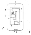
図2に、スマートフォンとして形成され、計算ユニット13を含む本発明によるモバイル端末5の実施例を示す。計算ユニット13は、位置算出ユニット15を有し、この位置算出ユニットに、グローバル座標系KSにおけるモバイル端末5の向きを決定するためにモバイル端末5のジャイロスコープ17及び磁気センサ19が接続される。3つの空間方向全てで作動するジャイロスコープ17及び同様に3つの空間方向すべてを考慮し、かつ地磁気におけるコンパスと同等の方位を示す磁気センサ19の他に、モバイル端末5の加速度を同様に3つの空間方向すべてで測定する加速度センサもまた、モバイル端末5内に配置することができる。
FIG. 2 shows an embodiment of the
位置算出ユニット15でそのように算出されたヨー角は、その位置を補足的にGPS位置データ又はモバイル通信若しくはWLANなどの追尾サービス11からの信号と比較する位置決定ユニット21に送られる。モバイル通信ネットワークにおける又は使用可能なWLANネットワークに対する位置決定はまた、位置算出について別法としてヨー角を介しても行うことができる。GPSを用いる衛星支援位置決定もまた、一般的である。
The yaw angle thus calculated by the
位置算出ユニット15によって決定されたヨー角および位置決定ユニット21によって決定された経路が、グローバル座標系KSにおいて走行操作計画ユニット23に出力される。この走行操作計画ユニット23では更に、運転者によって指定された出発位置S及び目標位置Eが入力され、これらの位置から、モバイル端末5は、出発位置Sから目標位置Eへの自動車1の走行操作に関する計画を決定し、その計画は、送信/受信ユニット9を介して自動車1の制御装置3に出力される。
The yaw angle determined by the
その際、計画された走行操作は、走行操作に対して計画された進路がまた実行可能であることをモバイル端末5が確認した場合にのみ、モバイル端末5から制御装置3に出力される。
At that time, the planned traveling operation is output from the
図3に示したように、制御装置3の送信/受信ユニット7は、計画された走行操作をモバイル端末5から受信する。制御装置3は、自動車固有のセンサ35、37、39によって出力された、車輪回転数、ヨー速度、及び磁場などのパラメータを処理する進路計画ユニット25を含む。任意選択的に、超音波センサ、レーダセンサ、レーザセンサ、又はカメラなどの自動車1の周辺センサ41によってデータをまた、検知することができ、そして制御装置3の進路計画ユニット25に送信することができる。進路計画ユニット25では、出発位置Sから目標位置Eへ移動されることとなる自動車1の設定進路が算出される。自動車1のこの設定進路は、進路制御ユニット27に出力され、このユニットは、同様に自動車固有のセンサ31、33、35から、車輪回転数、ヨー角、及び屈曲角などのパラメータを受信する。これらのパラメータ及び設定進路に応じて、進路制御ユニット27は、制御信号を設定ステアリング角の形式で自動車1のステアリング装置29に出力し、かつ、設定走行速度の形式でエンジン制御システム33及び/又はブレーキ装置31に出力する。
As shown in FIG. 3, the transmission / reception unit 7 of the
図4に明示したように、自動車1の出発位置Sは、グローバル座標系KSの原点に位置する。このグローバル座標系KSで、走行操作は、計画され、実行される。グローバル座標系内でのモバイル端末3の位置決定は、モバイル端末5のセンサを介して行われる。グローバル座標系KSにおける自動車15の位置決定は、自動車センサを介して行われる。
As clearly shown in FIG. 4, the starting position S of the automobile 1 is located at the origin of the global coordinate system KS. In this global coordinate system KS, the traveling operation is planned and executed. The position of the
図4に、トレーラ43を有する、駐車場を目指して移動されることとなる自動車1を示してあり、目標位置E、すなわち駐車場は、自動車固有のセンサによって検知することができない。したがって、自動車1は、トレーラ43の目標位置Eを決定する状況にない。モバイル端末5、例えば、スマートフォンを使用すると、トレーラ43を所望の目標位置Eに移送することは容易である。初めに、運転者は、自動車1内で運転席に座り、モバイル端末5の実際の位置を走行操作に対する出発位置Sとして指定する。別法として、出発位置はまた、自動車1の制御装置3によっても検知することができる。
FIG. 4 shows an automobile 1 having a trailer 43 to be moved toward the parking lot, and the target position E, that is, the parking lot cannot be detected by a sensor unique to the automobile. Therefore, the automobile 1 is not in a situation of determining the target position E of the trailer 43. When the
運転者が走行操作の出発位置を自動車1内の運転席で検知する場合、以下のセンサデータが検知される必要がある。
−地磁気における自動車1の向き、
−地磁気におけるモバイル端末5の向き、
−GPS又は他の追尾サービス11の位置データをまた利用することができる。
When the driver detects the starting position of the driving operation at the driver's seat in the automobile 1, the following sensor data needs to be detected.
-The orientation of the car 1 in geomagnetism,
- the orientation of the
GPS or other tracking service 11 location data can also be used.
それに続いて、運転者は、降車し、トレーラ43の所望の目標位置Eに移動する。
この地点でもまた、運転者は、駐車場を走行操作に対する目標位置Eとしてモバイル端末5上で指定する。更に、目標位置Eにおけるモバイル端末1の向きによって、目標位置Eにおけるトレーラ43の向きが決定される。
Subsequently, the driver gets off and moves to the desired target position E of the trailer 43.
Also at this point, the driver designates the parking lot on the
モバイル端末5の位置決定ユニット21が出発位置Sから目標位置Eまで記録する経路から、モバイル端末5の操作計画ユニット23において、トレーラ43を適切に移動させるための自動車1の走行操作が計画され、この走行操作は、制御装置3に送信される。制御装置3では、自動車1の設定進路が進路計画ユニット25で決定され、この設定進路を用いて、トレーラ43は、出発位置Sから目標位置Eに移動されることとなる。設定進路の決定後、運転者は、走行操作をモバイル端末5を介して開始し、進路制御ユニット27は、自動車1の自動走行を制御し、設定進路を前述の自動車固有のセンサ35、37、39、41のパラメータに基づいて補正し、制御命令をステアリング装置29又はエンジン制御システム33又はブレーキ装置31に出力する。自動車1に対するトレーラ43の動きは、屈曲角センサ(別に図示せず)を用いて検知され、この屈曲角センサは、好適には牽引棒の球状ヘッド内に一体化され、信号を制御装置3に送信する。その際、運転者は、自動車1を出発位置Sから目標位置Eまで動かすために、モバイル端末5のタッチスクリーン上で円を描く動きを連続して実行する。トレーラ43がその目標位置Eに到達した場合、到達したことが運転者に対してモバイル端末5上に表示される。
From the route recorded by the
モバイル端末5によって設定されるが、制御装置3によって補正された様々な走行進路は、モバイル端末3上だけではなく自動車1内のディスプレイ上にも表示される。その際、運転者は、自身が好む走行操作進路を選択できる。
Various travel routes set by the
モバイル端末5を使用するこの走行操作計画は、自動車5及びトレーラ43からなるタンデムの制御に制限されず、トレーラがない自動駐車機能に対する拡張としても使用することができる。図5は、トレーラがない自動車1を伴う、記述された走行操作を示す。このとき、この場合もまた、走行操作に対する出発位置Sは、自動車1に位置しており、出発位置は、同様にグローバル座標系KSの原点である。運転者が自動車1における出発位置を検知した後で、運転者は、モバイル端末5を伴って運転操作の目標位置Eに移動し、これをその場で検知する。その際、以下の信号がモバイル端末5において出発位置から目標位置Eまで算出される。
This travel operation plan using the
モバイル端末5のジャイロスコープ17に基づく3つのヨー速度の積分によって、グローバル座標系KSにおける3つのヨー角は、生成される。このヨー角は、グローバル座標系KSにおけるモバイル端末5の方向転換を記述する。それに加えて、ヨー角算出を支援するために、磁気センサ19を使用することができる。ヨー角は、加速度センサの3成分をグローバル座標系KSに変換するために使用される。グローバル座標系KSにおける3つの加速度成分の2回積分によって、運転者が移動した経路を記録することができる。更に、位置決定ユニット21での経路算出を支援するために、GPS位置データ又は他の追尾サービス11の位置データが使用される。
Three yaw angles in the global coordinate system KS are generated by integrating three yaw velocities based on the gyroscope 17 of the
運転者が所望の目標位置Eに到達した場合、運転者は、到達したことを示すモバイル端末5上でこれを確認する。そして、運転者は、図示された自動車1の方向転換によって、目標位置Eにおける自動車2の向きを設定する選択肢を、モバイル端末5上に有する。運転者がその選択肢を承諾すると、モバイル端末5の操作によって、走行操作を開始できる。走行操作中に、運転者は、自動車1による計画された走行操作の発進時に、モバイル端末1を介してわずかな経路補正を行うことができる、すなわち、運転者は、自動車1を計画された進路についてわずかな補正値の分だけ移動させることができる。
When the driver reaches the desired target position E, the driver confirms this on the
記載したようにモバイル端末5を用いて、様々な走行操作を計画すること、及び、例えば、通常の自動車の駐車場所への出入り又はトレーラ付きでの駐車場所への出入りを、ユーザが選択するために表示することができる。
For the user to select various driving operations using the
本発明は、好ましい実施例によって詳細に例示され、かつ説明されたにもかかわらず、本発明は、開示された例によって制限されず、他の変形形態は、本発明の保護範囲から逸脱することなく当業者によって導出可能である。したがって、多数の変形形態の可能性が存在することが明らかである。例示的に言及された実施形態は、ただ単に例を示しており、この例は、いかなる場合も、例えば、本発明の保護範囲、利用可能性、又は構成を制限するものとして解釈すべきではないことも同時に明らかである。より正確に言えば、上記の説明及び図の説明は、例示的な実施形態を完全に変換する立場に当業者を置き、当業者は、開示された本発明の概念の知見において、多様な変更を、例えば、例示的な実施形態で言及された個々の要素の機能又は配置を考慮して、特許請求の範囲及び、例えば、明細書における更なる説明などの特許請求の範囲の適法な同等物によって定義される保護範囲を逸脱することなく行うことができる。
Although the invention has been illustrated and described in detail by the preferred embodiments, the invention is not limited by the disclosed examples and other variations will depart from the protection scope of the invention. And can be derived by one skilled in the art. Thus, it is clear that there are many possible variations. The exemplary embodiments mentioned are merely examples, and in no way should this example be construed as limiting, for example, the protection scope, applicability, or configuration of the invention. It is also clear at the same time. More precisely, the above description and the description of the figures place those skilled in the art in a position to completely transform the exemplary embodiments, and those skilled in the art will be able to make various changes in the knowledge of the disclosed inventive concept. For example, considering the function or arrangement of individual elements referred to in the exemplary embodiments, and the legal equivalents of the claims, such as the further description in the specification. Can be made without departing from the scope of protection defined by.
Claims (9)
前記設定進路に沿った前記自動車(1)の走行が、前記自動車(1)又はモバイル端末(5)によって開始され、及び
前記出発位置(S)は、モバイル端末(5)又は前記自動車(1)によって決定され、前記目標位置(E)は、前記モバイル端末(5)によって決定される、
方法において、
前記設定進路は、前記出発位置(S)から前記目標位置(E)に運ばれる前記モバイル端末(5)で記録される進行中のデータを利用した走行操作計画に基づいて決定されること、及び
前記目標位置における前記自動車(1)の向きは、グローバル座標系(KS)における前記モバイル端末(5)の向きによって決定されることを特徴とする、方法。 A method of moving a car (1) from a starting position (S) to a target position (E) along a set course determined in the car (1),
The vehicle (1) travels along the set route by the vehicle (1) or the mobile terminal (5), and the starting position (S) is the mobile terminal (5) or the vehicle (1). The target position (E) is determined by the mobile terminal (5),
In the method
The set course is determined based on a driving operation plan using ongoing data recorded by the mobile terminal (5) carried from the starting position (S) to the target position (E); and Method according to claim 1, characterized in that the orientation of the car (1) at the target position is determined by the orientation of the mobile terminal (5) in a global coordinate system (KS).
前記自動車(1)の前記出発又は目標位置(S、E)の決定は、運転者によって又は運転者に係る事象によって起動され、前記出発又は目標位置(S、E)は、グローバル座標系(KS)における前記モバイル端末(5)の向きによって決定されることを特徴とする、方法。 The method of claim 1, comprising:
The determination of the departure or target position (S, E) of the car (1) is triggered by the driver or by an event relating to the driver, the departure or target position (S, E) being expressed in the global coordinate system (KS). ), Which is determined by the orientation of the mobile terminal (5).
前記グローバル座標系(KS)における前記モバイル端末(5)の向きは、前記自動車(1)に送信される前記モバイル端末(5)によって検知されたセンサデータを用いて決定されることを特徴とする、方法。 The method according to claim 1 or 2, wherein
The orientation of the mobile terminal (5) in the global coordinate system (KS) is determined using sensor data detected by the mobile terminal (5) transmitted to the automobile (1). ,Method.
前記自動車(1)の走行操作が実行されているとき、前記モバイル端末(5)によって前記自動車(1)の経路が補正され得ることを特徴とする、方法。 A method according to at least one of claims 1-3 .
Method, characterized in that the route of the car (1) can be corrected by the mobile terminal (5) when a driving operation of the car (1) is being performed.
前記設定進路は、前記出発位置(S)から前記目標位置(E)に運ばれる前記モバイル端末(5)で記録される進行中のデータを利用した走行操作計画に基づいて決定されること、及び
前記目標位置における前記自動車(1)の向きは、グローバル座標系における前記モバイル端末(5)の向きによって決定されることを特徴とする、装置。 A device for moving the vehicle (1) from the starting position (S) to the target position (E), which is connected to the steering device (29) and the engine control system (33) or the brake device (31) of the vehicle (1). The mobile terminal (5) determines the starting position (S) or the target position (E) of the automobile (1) via the wireless communication device (7, 9). Connected to the control device (3), and the control device (3) determines a set course based on a travel operation plan created by the mobile terminal (5), and the steering device (29) and the engine In the device that departs the set course by controlling the control (33) or the brake device (31),
The set course is determined based on a driving operation plan using ongoing data recorded by the mobile terminal (5) carried from the starting position (S) to the target position (E); and Device according to claim 1, characterized in that the orientation of the car (1) at the target position is determined by the orientation of the mobile terminal (5) in a global coordinate system.
前記制御装置(3)は、前記モバイル端末(5)によって作成された走行操作計画に基づいて設定進路を決定する進路計画ユニット(25)、および前記進路計画ユニット(25)と接続される、前記ステアリング装置(29)及び前記エンジン制御(33)又は前記ブレーキ装置(31)に制御命令を出力する進路制御ユニット(27)を含むことを特徴とする、装置。 The apparatus of claim 5 , comprising:
The control device (3) is connected to a route planning unit (25) for determining a set route based on a traveling operation plan created by the mobile terminal (5), and the route planning unit (25), A device comprising a steering device (29) and a course control unit (27) for outputting a control command to the engine control (33) or the brake device (31).
−計算ユニット(13)と、
−前記自動車(1)の出発位置(S)又は目標位置(E)又は可能な走行進路を決定するために前記計算ユニット(13)と接続される少なくとも1つの位置検知センサ(17、19)と、
−前記出発位置(S)、前記目標位置(E)、又は計画された走行操作を前記自動車(1)に送信する、前記計算ユニット(13)と接続された送信/受信ユニット(9)とを含む装置において、
−前記計算ユニット(13)は、位置算出ユニット(15)を含み、それに前記少なくとも1つの位置検知センサ(17、19)が接続され、それはグローバル座標系(KS)における前記装置の向きを決定し、
−前記計算ユニット(13)は、位置決定ユニット(21)を含み、それは前記位置算出ユニット(15)と接続され、前記自動車(1)の経路を決定し、
−前記計算ユニット(13)は、走行操作計画ユニット(23)を含み、それは前記位置算出ユニット(15)及び前記位置決定ユニット(21)と接続され、前記出発位置(S)から前記目標位置(E)に運ばれる前記装置で記録される進行中のデータを利用した前記走行操作を計画することを特徴とする、装置。 A device for planning a driving operation of an automobile,
A calculation unit (13);
-At least one position detection sensor (17, 19) connected to the calculation unit (13) in order to determine the starting position (S) or the target position (E) or possible driving path of the car (1); ,
A transmission / reception unit (9) connected to the calculation unit (13) for transmitting the starting position (S), the target position (E) or a planned driving operation to the vehicle (1); In the apparatus including
The calculation unit (13) comprises a position calculation unit (15), to which the at least one position detection sensor (17, 19) is connected, which determines the orientation of the device in the global coordinate system (KS); ,
The calculation unit (13) comprises a position determination unit (21), which is connected to the position calculation unit (15) and determines the route of the car (1);
The calculation unit (13) comprises a travel operation planning unit (23), which is connected to the position calculation unit (15) and the position determination unit (21) and from the starting position (S) to the target position ( E. Planning the driving operation using ongoing data recorded by the device carried to E) .
前記位置算出ユニット(15)は、ヨー角を算出するために、3つの空間方向すべてを含むセンサデータを出力するジャイロスコープ(1)又は磁気センサ(19)又は加速度センサと接続されることを特徴とする、装置。 The apparatus according to claim 7 , comprising:
The position calculation unit (15) is connected to a gyroscope (1), a magnetic sensor (19), or an acceleration sensor that outputs sensor data including all three spatial directions in order to calculate a yaw angle. And the device.
前記位置決定ユニット(21)は、無線追尾システム(11)と接続されることを特徴とする、装置。
The device according to claim 7 or 8 , comprising:
Device, characterized in that the positioning unit (21) is connected to a radio tracking system (11).
Applications Claiming Priority (3)
| Application Number | Priority Date | Filing Date | Title |
|---|---|---|---|
| DE102014011796.0A DE102014011796A1 (en) | 2014-08-08 | 2014-08-08 | Method and device for moving a vehicle to a destination position |
| DE102014011796.0 | 2014-08-08 | ||
| PCT/EP2015/001289 WO2016020024A1 (en) | 2014-08-08 | 2015-06-26 | Method and device for moving a vehicle into a target position |
Publications (3)
| Publication Number | Publication Date |
|---|---|
| JP2017524594A JP2017524594A (en) | 2017-08-31 |
| JP2017524594A5 JP2017524594A5 (en) | 2018-07-19 |
| JP6452801B2 true JP6452801B2 (en) | 2019-01-16 |
Family
ID=53524717
Family Applications (1)
| Application Number | Title | Priority Date | Filing Date |
|---|---|---|---|
| JP2017505146A Active JP6452801B2 (en) | 2014-08-08 | 2015-06-26 | Method and apparatus for moving a car to a target position |
Country Status (6)
| Country | Link |
|---|---|
| US (1) | US10179585B2 (en) |
| EP (1) | EP3177503B1 (en) |
| JP (1) | JP6452801B2 (en) |
| CN (1) | CN106660584B (en) |
| DE (1) | DE102014011796A1 (en) |
| WO (1) | WO2016020024A1 (en) |
Families Citing this family (16)
| Publication number | Priority date | Publication date | Assignee | Title |
|---|---|---|---|---|
| US9926008B2 (en) * | 2011-04-19 | 2018-03-27 | Ford Global Technologies, Llc | Trailer backup assist system with waypoint selection |
| DE102014019487A1 (en) | 2014-12-23 | 2016-06-23 | Daimler Ag | Method and device for locating a mobile unit in a vehicle |
| CN107444264A (en) * | 2016-05-31 | 2017-12-08 | 法拉第未来公司 | Use the object of camera calibration du vehicule |
| DE102016116860A1 (en) | 2016-09-08 | 2018-03-08 | Knorr-Bremse Systeme für Nutzfahrzeuge GmbH | System and method for operating autonomously driving commercial vehicles |
| DE102016116857A1 (en) | 2016-09-08 | 2018-03-08 | Knorr-Bremse Systeme für Nutzfahrzeuge GmbH | System and method for operating commercial vehicles |
| DE102016226008A1 (en) | 2016-12-22 | 2018-06-28 | Bayerische Motoren Werke Aktiengesellschaft | Remote control of a vehicle function of a motor vehicle by means of a touch gesture on the remote control |
| CN106970629B (en) * | 2017-05-22 | 2020-03-03 | 北京京东尚科信息技术有限公司 | Control method and device for automated guided vehicle |
| JP6819790B2 (en) * | 2017-08-10 | 2021-01-27 | 日産自動車株式会社 | Parking control method and parking control device |
| CN108563219B (en) * | 2017-12-29 | 2021-07-13 | 青岛海通机器人系统有限公司 | AGV avoidance method |
| US10705529B2 (en) | 2018-01-05 | 2020-07-07 | Honda Motor Co., Ltd. | Autonomous all-terrain vehicle (ATV) |
| JP6897597B2 (en) * | 2018-02-16 | 2021-06-30 | トヨタ自動車株式会社 | Parking support device |
| JP7032950B2 (en) * | 2018-02-19 | 2022-03-09 | 株式会社デンソーテン | Vehicle remote control device, vehicle remote control system and vehicle remote control method |
| US10976733B2 (en) | 2018-09-26 | 2021-04-13 | Ford Global Technologies, Llc | Interfaces for remote trailer maneuver assist |
| DE102019201186A1 (en) * | 2019-01-30 | 2020-07-30 | Continental Teves Ag & Co. Ohg | Ultrasound system and a method for locating a driver |
| CN112428981B (en) * | 2019-08-20 | 2022-05-24 | 北京图森智途科技有限公司 | Control method and device for automatically driving truck and automatically driving truck |
| CN114001745B (en) * | 2021-10-25 | 2023-11-24 | 东南大学 | Electric automobile parking guide system and position detection and evaluation method thereof |
Family Cites Families (16)
| Publication number | Priority date | Publication date | Assignee | Title |
|---|---|---|---|---|
| DE10117650A1 (en) | 2001-04-09 | 2002-10-10 | Daimler Chrysler Ag | Bringing vehicle to target position, involves outputting control commands to drive train, braking system and/or steering so vehicle can be steered to target position independently of driver |
| JP4052198B2 (en) * | 2003-07-25 | 2008-02-27 | 株式会社デンソー | Vehicle guidance device and route determination program |
| JP2008009913A (en) | 2006-06-30 | 2008-01-17 | Toyota Motor Corp | Automatic vehicle driving system |
| JP5115782B2 (en) * | 2006-11-07 | 2013-01-09 | アイシン精機株式会社 | Parking assistance device |
| US8682576B2 (en) * | 2008-12-04 | 2014-03-25 | Verizon Patent And Licensing Inc. | Navigation based on user-defined points and paths |
| JP5004031B2 (en) | 2008-12-09 | 2012-08-22 | 株式会社安川電機 | MOBILE BODY CONTROL METHOD, CONTROL DEVICE, AND MOBILE BODY SYSTEM |
| EP2560150B1 (en) * | 2010-04-12 | 2015-05-20 | Toyota Jidosha Kabushiki Kaisha | Vehicle remote operation system and on-board device |
| US8793036B2 (en) * | 2010-09-22 | 2014-07-29 | The Boeing Company | Trackless transit system with adaptive vehicles |
| KR20120086140A (en) * | 2011-01-25 | 2012-08-02 | 한국전자통신연구원 | Mobile and apparatus for providing auto valet parking service and method thereof |
| JP5729176B2 (en) | 2011-07-01 | 2015-06-03 | アイシン・エィ・ダブリュ株式会社 | Movement guidance system, movement guidance apparatus, movement guidance method, and computer program |
| DE102012200725A1 (en) | 2012-01-19 | 2013-07-25 | Robert Bosch Gmbh | Remote control of parking and maneuvering maneuvers of motor vehicles |
| JP2014065392A (en) * | 2012-09-25 | 2014-04-17 | Aisin Seiki Co Ltd | Portable terminal, remote control system, remote control method, and program |
| DE102012022087A1 (en) * | 2012-11-09 | 2014-05-15 | Volkswagen Aktiengesellschaft | Method for controlling parking operation of car, involves determining position of vehicle associated with and located outside of vehicle, and controlling parking operation in response to evaluation of position of reference device |
| KR102027917B1 (en) * | 2013-08-07 | 2019-10-02 | 현대모비스 주식회사 | Smartkey System using movement pattern recognition of a mobile device and operation method thereof |
| DE102013015349A1 (en) | 2013-09-17 | 2014-04-10 | Daimler Ag | Method for starting-up of vehicle for parking in parking lot, involves determining whether vehicle is to be parked in home parking lot or home parking zone when starting-up vehicle, based on identified environmental data of vehicle |
| DE102013016342A1 (en) * | 2013-09-30 | 2015-04-02 | Daimler Ag | Method for assisting reversing a team, driver assistance system |
-
2014
- 2014-08-08 DE DE102014011796.0A patent/DE102014011796A1/en not_active Withdrawn
-
2015
- 2015-06-26 JP JP2017505146A patent/JP6452801B2/en active Active
- 2015-06-26 WO PCT/EP2015/001289 patent/WO2016020024A1/en active Application Filing
- 2015-06-26 EP EP15734571.1A patent/EP3177503B1/en active Active
- 2015-06-26 US US15/502,292 patent/US10179585B2/en active Active
- 2015-06-26 CN CN201580042522.0A patent/CN106660584B/en active Active
Also Published As
| Publication number | Publication date |
|---|---|
| CN106660584B (en) | 2020-09-11 |
| US20170225679A1 (en) | 2017-08-10 |
| WO2016020024A1 (en) | 2016-02-11 |
| EP3177503B1 (en) | 2018-10-10 |
| CN106660584A (en) | 2017-05-10 |
| US10179585B2 (en) | 2019-01-15 |
| EP3177503A1 (en) | 2017-06-14 |
| DE102014011796A1 (en) | 2016-02-11 |
| JP2017524594A (en) | 2017-08-31 |
Similar Documents
| Publication | Publication Date | Title |
|---|---|---|
| JP6452801B2 (en) | Method and apparatus for moving a car to a target position | |
| US11845473B2 (en) | Autonomous driving apparatus including a driving state switcher | |
| EP3088280B1 (en) | Autonomous driving vehicle system | |
| US9796416B2 (en) | Automated driving apparatus and automated driving system | |
| US10202123B2 (en) | Vehicle control system | |
| CN109891472B (en) | Vehicle control system, vehicle control method, and storage medium | |
| JP2017524594A5 (en) | ||
| US9896098B2 (en) | Vehicle travel control device | |
| CN109923018B (en) | Vehicle control system, vehicle control method, and storage medium | |
| US10053090B2 (en) | Method for providing user-defined customization of a vehicle | |
| JP2019532292A (en) | Autonomous vehicle with vehicle location | |
| CN102910167A (en) | Driving assistance apparatus for assistance with driving along narrow roadways | |
| US20180056745A1 (en) | Methods And Systems To Calculate And Store GPS Coordinates Of Location-Based Features | |
| US20200073398A1 (en) | System and methods for reverse braking during automated hitch alignment | |
| WO2020039786A1 (en) | Automatic travel system | |
| US11787395B2 (en) | Automated valet parking system | |
| US20220212657A1 (en) | Automated valet parking system, control method of automated valet parking system, and autonomous driving vehicle | |
| JP2020056733A (en) | Vehicle control device | |
| JP2019089513A (en) | Vehicle control device and parking space | |
| US20220258727A1 (en) | Automated valet parking system, control method of automated valet parking system, and autonomous driving vehicle | |
| JP7108499B2 (en) | automatic driving system | |
| CN109923374B (en) | Method and device for interacting with a local guidance system in a motor vehicle | |
| JP7225297B2 (en) | Driving support device, driving support method, and program | |
| JP6997052B2 (en) | Autonomous driving system | |
| CN114423656A (en) | Vehicle remote control method and vehicle remote control device |
Legal Events
| Date | Code | Title | Description |
|---|---|---|---|
| A977 | Report on retrieval |
Free format text: JAPANESE INTERMEDIATE CODE: A971007 Effective date: 20180111 |
|
| A131 | Notification of reasons for refusal |
Free format text: JAPANESE INTERMEDIATE CODE: A131 Effective date: 20180116 |
|
| A601 | Written request for extension of time |
Free format text: JAPANESE INTERMEDIATE CODE: A601 Effective date: 20180413 |
|
| A524 | Written submission of copy of amendment under article 19 pct |
Free format text: JAPANESE INTERMEDIATE CODE: A524 Effective date: 20180611 |
|
| A131 | Notification of reasons for refusal |
Free format text: JAPANESE INTERMEDIATE CODE: A131 Effective date: 20180821 |
|
| A521 | Request for written amendment filed |
Free format text: JAPANESE INTERMEDIATE CODE: A523 Effective date: 20181031 |
|
| TRDD | Decision of grant or rejection written | ||
| A01 | Written decision to grant a patent or to grant a registration (utility model) |
Free format text: JAPANESE INTERMEDIATE CODE: A01 Effective date: 20181120 |
|
| A61 | First payment of annual fees (during grant procedure) |
Free format text: JAPANESE INTERMEDIATE CODE: A61 Effective date: 20181211 |
|
| R150 | Certificate of patent or registration of utility model |
Ref document number: 6452801 Country of ref document: JP Free format text: JAPANESE INTERMEDIATE CODE: R150 |
|
| R250 | Receipt of annual fees |
Free format text: JAPANESE INTERMEDIATE CODE: R250 |
|
| R250 | Receipt of annual fees |
Free format text: JAPANESE INTERMEDIATE CODE: R250 |
|
| S531 | Written request for registration of change of domicile |
Free format text: JAPANESE INTERMEDIATE CODE: R313531 |
|
| S533 | Written request for registration of change of name |
Free format text: JAPANESE INTERMEDIATE CODE: R313533 |
|
| R350 | Written notification of registration of transfer |
Free format text: JAPANESE INTERMEDIATE CODE: R350 |
|
| R250 | Receipt of annual fees |
Free format text: JAPANESE INTERMEDIATE CODE: R250 |