EP3176920A2 - Covering device for an electronics enclosure of an electric motor - Google Patents
Covering device for an electronics enclosure of an electric motor Download PDFInfo
- Publication number
- EP3176920A2 EP3176920A2 EP16200878.3A EP16200878A EP3176920A2 EP 3176920 A2 EP3176920 A2 EP 3176920A2 EP 16200878 A EP16200878 A EP 16200878A EP 3176920 A2 EP3176920 A2 EP 3176920A2
- Authority
- EP
- European Patent Office
- Prior art keywords
- electronics housing
- segment
- cover
- base segment
- covering device
- Prior art date
- Legal status (The legal status is an assumption and is not a legal conclusion. Google has not performed a legal analysis and makes no representation as to the accuracy of the status listed.)
- Granted
Links
- 238000001816 cooling Methods 0.000 claims abstract description 49
- 239000007787 solid Substances 0.000 claims abstract description 7
- 238000011109 contamination Methods 0.000 description 4
- 238000011161 development Methods 0.000 description 3
- 230000018109 developmental process Effects 0.000 description 3
- 230000002349 favourable effect Effects 0.000 description 3
- 230000000295 complement effect Effects 0.000 description 2
- 238000009434 installation Methods 0.000 description 2
- 230000001681 protective effect Effects 0.000 description 2
- 230000005484 gravity Effects 0.000 description 1
Images


Classifications
-
- H—ELECTRICITY
- H02—GENERATION; CONVERSION OR DISTRIBUTION OF ELECTRIC POWER
- H02K—DYNAMO-ELECTRIC MACHINES
- H02K11/00—Structural association of dynamo-electric machines with electric components or with devices for shielding, monitoring or protection
- H02K11/0094—Structural association with other electrical or electronic devices
-
- H—ELECTRICITY
- H02—GENERATION; CONVERSION OR DISTRIBUTION OF ELECTRIC POWER
- H02K—DYNAMO-ELECTRIC MACHINES
- H02K11/00—Structural association of dynamo-electric machines with electric components or with devices for shielding, monitoring or protection
- H02K11/30—Structural association with control circuits or drive circuits
- H02K11/33—Drive circuits, e.g. power electronics
-
- H—ELECTRICITY
- H02—GENERATION; CONVERSION OR DISTRIBUTION OF ELECTRIC POWER
- H02K—DYNAMO-ELECTRIC MACHINES
- H02K5/00—Casings; Enclosures; Supports
- H02K5/04—Casings or enclosures characterised by the shape, form or construction thereof
- H02K5/18—Casings or enclosures characterised by the shape, form or construction thereof with ribs or fins for improving heat transfer
-
- H—ELECTRICITY
- H02—GENERATION; CONVERSION OR DISTRIBUTION OF ELECTRIC POWER
- H02K—DYNAMO-ELECTRIC MACHINES
- H02K5/00—Casings; Enclosures; Supports
- H02K5/04—Casings or enclosures characterised by the shape, form or construction thereof
- H02K5/20—Casings or enclosures characterised by the shape, form or construction thereof with channels or ducts for flow of cooling medium
- H02K5/207—Casings or enclosures characterised by the shape, form or construction thereof with channels or ducts for flow of cooling medium with openings in the casing specially adapted for ambient air
-
- H—ELECTRICITY
- H02—GENERATION; CONVERSION OR DISTRIBUTION OF ELECTRIC POWER
- H02K—DYNAMO-ELECTRIC MACHINES
- H02K7/00—Arrangements for handling mechanical energy structurally associated with dynamo-electric machines, e.g. structural association with mechanical driving motors or auxiliary dynamo-electric machines
- H02K7/14—Structural association with mechanical loads, e.g. with hand-held machine tools or fans
-
- H—ELECTRICITY
- H02—GENERATION; CONVERSION OR DISTRIBUTION OF ELECTRIC POWER
- H02K—DYNAMO-ELECTRIC MACHINES
- H02K9/00—Arrangements for cooling or ventilating
- H02K9/02—Arrangements for cooling or ventilating by ambient air flowing through the machine
-
- H—ELECTRICITY
- H05—ELECTRIC TECHNIQUES NOT OTHERWISE PROVIDED FOR
- H05K—PRINTED CIRCUITS; CASINGS OR CONSTRUCTIONAL DETAILS OF ELECTRIC APPARATUS; MANUFACTURE OF ASSEMBLAGES OF ELECTRICAL COMPONENTS
- H05K5/00—Casings, cabinets or drawers for electric apparatus
- H05K5/02—Details
- H05K5/03—Covers
-
- H—ELECTRICITY
- H05—ELECTRIC TECHNIQUES NOT OTHERWISE PROVIDED FOR
- H05K—PRINTED CIRCUITS; CASINGS OR CONSTRUCTIONAL DETAILS OF ELECTRIC APPARATUS; MANUFACTURE OF ASSEMBLAGES OF ELECTRICAL COMPONENTS
- H05K7/00—Constructional details common to different types of electric apparatus
- H05K7/20—Modifications to facilitate cooling, ventilating, or heating
- H05K7/20009—Modifications to facilitate cooling, ventilating, or heating using a gaseous coolant in electronic enclosures
- H05K7/20136—Forced ventilation, e.g. by fans
- H05K7/20145—Means for directing air flow, e.g. ducts, deflectors, plenum or guides
Definitions
- the invention relates to a covering device for an electronics housing of an electric motor.
- the engine electronics is received, on which extends a built-in electronics housing cooling air passage over.
- Electric motors from the field of the invention are used in particular for driving fans. They are regularly mounted on the stator bushing on mounting walls or supporting structures, whereby effective cooling is difficult.
- the power range and the service life of the electric motor are determined by the component temperatures reached during operation, in particular the integrated motor electronics, electrical power components, bearings and motor drive components. For this reason, a sufficient and permanent cooling of the components of great importance.
- the invention is therefore based on the object to provide a variably usable cover device for an electric motor with electronics housing, which protects an electronics housing opening for the intake of cooling air against clogging by solids. It is another object of the invention to provide an electric motor, the cooling of which is permanently ensured in outdoor use.
- a covering device for an electronics housing of an electric motor which has at least one base segment and at least one rib formed on the base segment, wherein the base segment is geometrically designed to cover at least in sections an electronics housing opening for sucking in a cooling air volume flow Electronics housing opening against ingress of solids at least partially close.
- the base segment forms, with the at least one rib, at least one flow channel which is fluidically connectable to the electronics housing opening, and wherein the cover device is designed as a modular insert for the electronics housing (2).
- the base segment covers the electronics housing opening over conventional protective grids surface, but with the at least one rib on the base segment provides an always open flow channel for the suction of cooling air in the electronics housing opening and thus in a cooling channel in the electronics housing.
- the at least one flow channel runs perpendicular to the suction direction, which is determined by the orientation of the electronics housing opening.
- the suction takes place in the axial direction parallel to the axis of rotation of the electric motor.
- the at least one flow channel then preferably runs in the radial direction. If solids such as leaves fall axially on the electronics housing opening and the cover, the intake of cooling air takes place in the radial direction through the at least one flow channel.
- a plurality of ribs are formed as axial ribs on the base segment, which each form a flow channel with the surface of the base segment. The base segment thus covers the electronics housing opening with a first side and, together with the axial ribs, forms the flow channels with the opposite surface side.
- the covering device is formed from a base segment and an axially spaced cover segment, wherein between the base segment and the cover segment the spaced apart ribs extend, which also in the embodiment with base and cover segment between them form the flow channels, which are fluidly connected to the electronics housing opening.
- the design of the covering device with base segment and cover segment offers the advantage of a defined support surface for dirt such as leaves, leaves or the like on the deck segment, while at the same time one or more flow channels between base segment and cover segment are ensured.
- the flow can be optimized by the geometry of the flow channels. The cover thus serves as a spoiler for defined cooling.
- the cover device is annular.
- at least the base segment of the covering device is conical and thus provides a nozzle-like air guide radially inwardly toward the electronics housing opening.
- an embodiment is providable, in which the cover segment is arranged radially inwardly offset relative to a radial outer edge of the base segment. The air inlet between the base segment and cover segment at the radial outer edge is thereby increased.
- embodiments are encompassed in which the cover segment in the projection does not completely cover the base segment, so that the ribs or axial ribs have free axial ends, ie not covered by the cover segment.
- the ribs or axial ribs extend radially inwardly beyond a radial inner edge of the cover disk in the radial direction.
- the ribs or axial ribs each have a radial outer edge which directly connects the radial outer edge of the base segment and a radial outer edge of the deck segment.
- the radial outer edges thus form a lattice-like radial termination between the base segment and cover segment.
- the ribs or axial ribs terminate flush with the radially outer edge of the base segment and / or flush with the radially outer edge of the deck segment. As a result, no regions of the ribs or axial ribs remain on the covering device, in which dirt could catch. Rather, lying dirt can be removed, for example by wind again.
- the ribs or axial ribs of the covering device extend in a straight line radially outward.
- an axial distance between the base segment and the cover segment is advantageously constant, so that the base segment and the cover segment run at least substantially parallel.
- the covering device is designed as a modular insert for the electronics housing, so that it can be variably used, retrofitted or exchanged.
- this allows the use of certain covering devices for different mounting positions of the electric motor, e.g. horizontal or vertical.
- the covering device is preferably formed in one piece.
- the base segment and the ribs or axial ribs are in one piece.
- base segment and deck segment is a one-piece Design also preferred.
- the cover device can also be composed of several circumferential segments.
- the invention further comprises an electric motor which comprises an electronics housing with motor electronics accommodated therein, the electronics housing having an integrated cooling air channel extending past the engine electronics at least in the axial direction, through which the cooling air volume flow can be conveyed and which ends at the electronics housing opening.
- the covering device described above is fastened to the electric motor so that the electronics housing opening always remains open and is protected against clogging by solids. About the cover and the electronics housing opening is always the air flow in the cooling air duct sucked.
- the electronics housing opening of the electronics housing is formed by cooling ribs.
- the ribs or axial ribs of the covering device extend parallel and / or in radial extension in alignment with the cooling ribs of the electronics housing.
- the axial ribs of the cover are arranged in a favorable abutting the ribs of the electronics housing.
- the electronics housing opening has a radial opening section, which is aligned perpendicular to the axis of rotation of the electric motor.
- the radial opening portion is preferably fluidly connected directly to the flow channel of the cover device to allow suction of cooling air in a direction perpendicular to the axis of rotation of the electric motor.
- the covering device lies flat on the axial end faces of the cooling fins of the electronics housing with the base segment.
- the axial ribs of the covering device can be formed in a predefined shape and extent in order to interact with the electronics housing opening in the best possible way in terms of flow.
- the axial ribs can narrow the flow channels in the direction of the electronics housing opening, in order to increase the flow velocity of the sucked air volume flow.
- the cover device can thus serve not only as protection against contamination, but as a flow guide towards the electronics housing opening.
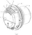
- FIGS. 1 to 3 is in a first embodiment, an electric motor 1 with an electronics housing 2 and an axially connected thereto stator bush 28 with rotor 30 shown. Between the electronics housing 2 and the rotor 30, an impeller 29 is arranged, which generates an air volume flow during engine operation, which flows in the axial direction for cooling the motor electronics received in the electronics housing 2 through the cooling air channel 6 integrated in the electronics housing 2.
- the cooling air channel 6 extends up to the axial electronics housing opening 7 in the axial end portion of the electronics housing 2.
- On the electronics housing 2 is the outside of the axial electronics housing opening 7 adjacent and this partially covering the covering 3 arranged.
- the covering device 3 is designed as a ring segment and has a plurality of linearly extending in the radial direction axial ribs 13, which each form radial flow channels 8 between them.
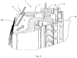
- the cover 3 is in Fig. 2 screwed to the electronics housing 2, wherein the radial Opening portion 10 of the electronics housing opening 7 is fluidly connected to the radial flow channels 8.
- the electronics housing opening 7 of the electronics housing 2 is formed by the cooling fins 12 formed on the electronics housing 2.
- the cooling fins 12 are spaced from each other in the circumferential direction and extend as flat, flat plate body in the axial and radial directions.
- the covering device 3 has, as the main body of the ring segment, a base segment 4 designed as a base plate, on the upper side of which the one-piece axial ribs 13 extending in a straight line in the radial direction are formed.
- the cover 3 is flat on axial end faces of the cooling fins 12 of the electronics housing 2.
- the axial ribs 13 of the cover 3 extend in a radial extension in alignment and abutting the cooling fins 12 of the electronics housing 2, so that the flow channels 8 of the cover 3 pass directly into the formed by the cooling fins 12 radial opening portion 10 of the electronics housing opening 7.
- FIG. 3 shows by way of example contamination of the axial side of the channel entrance 7 of the embodiment according to FIG. 2 with foliage 100, so that the inflow of the illustrated with arrows air volume flow into the cooling air duct 6 takes place mainly from the radial direction through the flow channels 8 of the cover 3.
- FIG. 4 shows a first alternative embodiment of an electronics housing 2 with cover 3 in an exploded view.
- the cover 3 corresponds in terms of its features according to the embodiment Fig. 1
- her Fig. 1 formed as a closed ring, which is fully brought to the cooling fins 12 of the electronics housing 2 to rest.
- the cooling fins 12 have frontally a complementary shape to the tapered base segment 4 of the cover 3.
- the axial ribs 13 extend in extension and parallel to the cooling fins 12 of the electronics housing 2, so that the flow channels 8 of the cover 3 pass directly into the formed by the cooling fins 12 radial opening portion 10 of the electronics housing opening 7.
- the cooling air duct 6 surrounds the entire electronics housing 2 in the circumferential direction in this embodiment.
- the cooling ribs 12 of the electronics housing 2 extend in the axial direction further beyond the electronics housing opening 7 to the axial end portion of the electronics housing 2. They form recesses on the outer surface of the electronics housing 2 and thereby increase the total cooling surface.
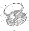
- the cover device 3 is an exchangeable modular component and has, in addition to the base segment 4, the cover segment 5, wherein between the base segment 4 and the cover segment 5, the mutually spaced axial ribs 13 extend, each of which form the radial flow channels 8.
- the cover 3 according to FIG. 5 is a one-piece ring segment which is screwed to the electronics housing 2.
- the base segment 4 has a conically tapering cross section which is complementary to the frontal profile of the cooling fins 12.
- the cover segment 5 extends in the radial direction up to the electronics housing opening 7, which is formed by the cooling ribs 12. Opposite the radial outer edge of the base segment 4 is the cover segment 5 with respect to its radial Outer edge arranged radially inwardly offset.
- the axial ribs 13 extend with their radial outer edges obliquely between the base segment 4 and the cover segment 5 and each terminate flush with the radial outer edge of the base segment 4 and the radial outer edge of the deck segment 5.
- the axial distance between the base segment 4 and the cover segment 5 is constant. The inflow occurs at a contamination of the axial side of the electronics housing opening 7 radially over the flow channels 8, which are formed between the axial ribs 13 and the cover and base segments 5, 4th
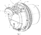
- FIGS. 7 and 8th show a further embodiment, which differs from the embodiment of the Figures 5 and 6 differs in that the cover segment 5 of the cover 3 completely covers the electronics housing opening 7 and therefore the cooling fins 12 in the axial direction. This creates an exclusively radial inflow direction. Therefore, the embodiment is suitable for a direction of installation of the electric motor in the vertical direction, so that falling leaves on the deck segment 5 comes to rest, but the radial flow channels 8 always remain open.
- the features are identical to the execution proper FIG. 5 and on the execution according to FIG. 7 transferable.
- the invention is not limited in its execution to the above-mentioned preferred embodiments. Also included are embodiments in which a cover according to FIG. 5 as a full ring according to FIG. 4 formed and placed on ribs 12 of the electronics housing 2 over its entire circumference. Also, the axial ribs 13 of the cover device may extend radially inwardly beyond a radially inner edge of the deck segment 5 and into the ribs 12 of the electronics housing be brought to the plant or replace the axially outwardly free standing portion of the cooling fins 12.
- the cover device is connected with a geometry according to the embodiments shown above directly to the electronics housing 2, cohesively or in one piece. An example of this would be a complete die cast part.
- the covering device is made of plastic.
Abstract
Die Erfindung betrifft eine Abdeckvorrichtung (3) für ein Elektronikgehäuse (2) eines Elektromotors (1) mit zumindest einem Basissegment (4) und zumindest einer an dem Basissegment (4) ausgebildeten Rippe (13), wobei das Basissegment (4) geometrisch ausgebildet ist, eine Elektronikgehäuseöffnung zur Ansaugung eines Kühlluftvolumenstroms zumindest abschnittsweise zu überdecken, um die Elektronikgehäuseöffnung gegen Eindringen von Feststoffen zumindest abschnittsweise zu verschließen, und das Basissegment (4) mit der zumindest einen Rippe (13) zumindest einen Strömungskanal (8) ausbildet, der mit der Elektronikgehäuseöffnung strömungsverbindbar ist, und wobei die Abdeckvorrichtung als modularer Einsatz für das Elektronikgehäuse (2) ausgebildet ist.The invention relates to a covering device (3) for an electronics housing (2) of an electric motor (1) having at least one base segment (4) and at least one rib (13) formed on the base segment (4), wherein the base segment (4) is geometrically formed to cover at least sections an electronics housing opening for sucking a cooling air volume flow to at least partially close the electronics housing opening against ingress of solids, and the base segment (4) with the at least one rib (13) at least one flow channel (8) forms, with the electronics housing opening is strömungsverbindbar, and wherein the cover device is designed as a modular insert for the electronics housing (2).
Description
Die Erfindung betrifft eine Abdeckvorrichtung für ein Elektronikgehäuse eines Elektromotors. In dem Elektronikgehäuse wird die Motorelektronik aufgenommen, an der sich ein in das Elektronikgehäuse integrierter Kühlluftkanal vorbei erstreckt.The invention relates to a covering device for an electronics housing of an electric motor. In the electronics housing, the engine electronics is received, on which extends a built-in electronics housing cooling air passage over.
Elektromotoren aus dem Bereich der Erfindung werden insbesondere zum Antrieb von Ventilatoren eingesetzt. Dabei werden sie regelmäßig über die Statorbuchse an Befestigungswänden oder Tragkonstruktionen montiert, wodurch eine effektive Kühlung erschwert wird. Der Leistungsbereich sowie die Lebensdauer des Elektromotors bestimmen sich unter anderem auch nach den im Betrieb erreichten Bauteiltemperaturen, vor allem der integrierten Motorelektronik, elektrischen Leistungsbauteile, Lager und Motorantriebsbauteile. Aus diesem Grund ist eine ausreichende und dauerhafte Kühlung der Bauteile von großer Bedeutung.Electric motors from the field of the invention are used in particular for driving fans. They are regularly mounted on the stator bushing on mounting walls or supporting structures, whereby effective cooling is difficult. Among other things, the power range and the service life of the electric motor are determined by the component temperatures reached during operation, in particular the integrated motor electronics, electrical power components, bearings and motor drive components. For this reason, a sufficient and permanent cooling of the components of great importance.
Aus dem Stand der Technik, beispielsweise der
Der Erfindung liegt deshalb die Aufgabe zugrunde, eine variabel einsetzbare Abdeckvorrichtung für einen Elektromotor mit Elektronikgehäuse bereitzustellen, die eine Elektronikgehäuseöffnung zur Ansaugung von Kühlluft gegenüber einem Verstopfen durch Feststoffe schützt. Ferner ist es Aufgabe der Erfindung, einen Elektromotor bereit zu stellen, dessen Kühlung im Außeneinsatz dauerhaft sichergestellt ist.The invention is therefore based on the object to provide a variably usable cover device for an electric motor with electronics housing, which protects an electronics housing opening for the intake of cooling air against clogging by solids. It is another object of the invention to provide an electric motor, the cooling of which is permanently ensured in outdoor use.
Diese Aufgabe wird gelöst durch die Merkmalskombination gemäß der Patentansprüche 1 und 13.This object is achieved by the feature combination according to
Erfindungsgemäß wird eine Abdeckvorrichtung für ein Elektronikgehäuse eines Elektromotors vorgeschlagen, das zumindest ein Basissegment und zumindest eine an dem Basissegment ausgebildeten Rippe aufweist, wobei das Basissegment geometrisch derart ausgebildet ist, eine Elektronikgehäuseöffnung zur Ansaugung eines Kühlluftvolumenstroms zumindest abschnittsweise flächig zu überdecken, um die Elektronikgehäuseöffnung gegen Eindringen von Feststoffen zumindest abschnittsweise zu verschließen. Das Basissegment bildet mit der zumindest einen Rippe zumindest einen Strömungskanal aus, der mit der Elektronikgehäuseöffnung strömungsverbindbar ist, und wobei die Abdeckvorrichtung als modularer Einsatz für das Elektronikgehäuse (2) ausgebildet ist.According to the invention, a covering device for an electronics housing of an electric motor is proposed, which has at least one base segment and at least one rib formed on the base segment, wherein the base segment is geometrically designed to cover at least in sections an electronics housing opening for sucking in a cooling air volume flow Electronics housing opening against ingress of solids at least partially close. The base segment forms, with the at least one rib, at least one flow channel which is fluidically connectable to the electronics housing opening, and wherein the cover device is designed as a modular insert for the electronics housing (2).
Das Basissegment überdeckt die Elektronikgehäuseöffnung gegenüber herkömmlichen Schutzgittern flächig, bietet jedoch mit der zumindest einen Rippe an dem Basissegment einen stets offenen Strömungskanal zur Ansaugung von Kühlluft in die Elektronikgehäuseöffnung und mithin in einen Kühlkanal im Elektronikgehäuse.The base segment covers the electronics housing opening over conventional protective grids surface, but with the at least one rib on the base segment provides an always open flow channel for the suction of cooling air in the electronics housing opening and thus in a cooling channel in the electronics housing.
In einer vorteilhaften Ausführung verläuft der zumindest eine Strömungskanal senkrecht zur Ansaugrichtung, die bestimmt wird durch die Ausrichtung der Elektronikgehäuseöffnung. Üblicherweise erfolgt die Ansaugung in axialer Richtung parallel zur Rotationsachse des Elektromotors. Der zumindest eine Strömungskanal verläuft dann vorzugsweise in radialer Richtung. Wenn Feststoffe wie Laub axial auf die Elektronikgehäuseöffnung und die Abdeckvorrichtung fallen, erfolgt die Ansaugung von Kühlluft in radialer Richtung durch den zumindest einen Strömungskanal. In einer günstigen Ausführung sind an dem Basissegment mehrere Rippen als Axialrippen ausgebildet, die mit der Oberfläche des Basissegments jeweils einen Strömungskanal bilden. Das Basissegment überdeckt somit mit einer ersten Seite die Elektronikgehäuseöffnung und bildet mit der gegenüberliegenden Oberflächenseite zusammen mit den Axialrippen die Strömungskanäle.In an advantageous embodiment, the at least one flow channel runs perpendicular to the suction direction, which is determined by the orientation of the electronics housing opening. Usually, the suction takes place in the axial direction parallel to the axis of rotation of the electric motor. The at least one flow channel then preferably runs in the radial direction. If solids such as leaves fall axially on the electronics housing opening and the cover, the intake of cooling air takes place in the radial direction through the at least one flow channel. In a favorable embodiment, a plurality of ribs are formed as axial ribs on the base segment, which each form a flow channel with the surface of the base segment. The base segment thus covers the electronics housing opening with a first side and, together with the axial ribs, forms the flow channels with the opposite surface side.
In einer weiteren Ausführungsvariante ist die Abdeckvorrichtung aus einem Basissegment und einem axial hierzu beabstandeten Decksegment gebildet, wobei sich zwischen dem Basissegment und dem Decksegment die zueinander beabstandet die Rippen erstrecken, die auch in der Ausführung mit Basis- und Decksegment jeweils zwischen sich die Strömungskanäle bilden, die mit der Elektronikgehäuseöffnung strömungsverbunden sind. Die Ausführung der Abdeckvorrichtung mit Basissegment und Decksegment bietet den Vorteil einer definierten Auflagefläche für Verschmutzungen wie Laub, Blätter oder dergleichen auf dem Decksegment, während gleichzeitig ein oder mehrere Strömungskanäle zwischen Basissegment und Decksegment gewährleistet sind. Zudem kann die Strömung durch die Geometrie der Strömungskanäle optimiert werden. Die Abdeckvorrichtung dient mithin als Luftleitelement zur definierten Kühlung.In a further embodiment variant, the covering device is formed from a base segment and an axially spaced cover segment, wherein between the base segment and the cover segment the spaced apart ribs extend, which also in the embodiment with base and cover segment between them form the flow channels, which are fluidly connected to the electronics housing opening. The design of the covering device with base segment and cover segment offers the advantage of a defined support surface for dirt such as leaves, leaves or the like on the deck segment, while at the same time one or more flow channels between base segment and cover segment are ensured. In addition, the flow can be optimized by the geometry of the flow channels. The cover thus serves as a spoiler for defined cooling.
In einem Ausführungsbeispiel ist die Abdeckvorrichtung ringförmig. In einer Weiterbildung ist zumindest das Basissegment der Abdeckvorrichtung konisch ausgebildet und bietet somit eine düsenartige Luftführung nach radial einwärts hin zur Elektronikgehäuseöffnung.In one embodiment, the cover device is annular. In a further development, at least the base segment of the covering device is conical and thus provides a nozzle-like air guide radially inwardly toward the electronics housing opening.
Ferner ist eine Ausführung vorsehbar, bei der das Decksegment gegenüber einem radialen Außenrand des Basissegments radial einwärts versetzt angeordnet ist. Der Lufteinlass zwischen Basissegment und Decksegment am radialen Außenrand wird hierdurch vergrößert. Zudem werden Ausführungen umfasst, bei denen das Decksegment in der Projektion das Basissegment nicht vollständig überdeckt, so dass die Rippen bzw. Axialrippen freie, d.h. vom Decksegment nicht überdeckte axiale Stirnseiten aufweisen. Die Rippen bzw. Axialrippen erstrecken sich dabei in radialer Richtung über einen radialen Innenrand der Deckscheibe hinaus radial einwärts. Hierdurch sind durch die Abdeckvorrichtung selbst zwei Einströmrichtungen radial und axial entlang der Rippen bzw. Axialrippen gewährleistbar. Soweit zwei Einströmrichtungen gegeben sind, spielt die Einbaurichtung des Elektromotors keine Rolle, da eine Verschmutzung durch Laub, Blätter und dergleichen schwerkraftbedingt üblicherweise nur von einer Seite erfolgt.Furthermore, an embodiment is providable, in which the cover segment is arranged radially inwardly offset relative to a radial outer edge of the base segment. The air inlet between the base segment and cover segment at the radial outer edge is thereby increased. In addition, embodiments are encompassed in which the cover segment in the projection does not completely cover the base segment, so that the ribs or axial ribs have free axial ends, ie not covered by the cover segment. The ribs or axial ribs extend radially inwardly beyond a radial inner edge of the cover disk in the radial direction. As a result, two inflow directions can be ensured radially and axially along the ribs or axial ribs by the covering device itself. As far as two directions of inflow are given, the direction of installation of the electric motor does not matter, as contamination by leaves, leaves and the like due to gravity usually done only from one side.
Ferner ist günstig, wenn die Rippen bzw. Axialrippen jeweils eine radiale Außenkante aufweisen, welche den radialen Außenrand des Basissegments und einen radialen Außenrand des Decksegments unmittelbar verbindet. Die radialen Außenkanten bilden somit einen gitterartigen radialen Abschluss zwischen Basissegment und Decksegment.Furthermore, it is favorable if the ribs or axial ribs each have a radial outer edge which directly connects the radial outer edge of the base segment and a radial outer edge of the deck segment. The radial outer edges thus form a lattice-like radial termination between the base segment and cover segment.
In einem Ausführungsbeispiel schließen die Rippen bzw. Axialrippen bündig mit dem radialen Außenrand des Basissegments und/oder bündig mit dem radialen Außenrand des Decksegments ab. Es verbleiben hierdurch keine Bereiche der Rippen bzw. Axialrippen an der Abdeckvorrichtung, in denen sich Verschmutzungen verfangen könnten. Vielmehr können aufliegende Verschmutzungen beispielsweise durch Wind auch wieder entfernt werden.In one embodiment, the ribs or axial ribs terminate flush with the radially outer edge of the base segment and / or flush with the radially outer edge of the deck segment. As a result, no regions of the ribs or axial ribs remain on the covering device, in which dirt could catch. Rather, lying dirt can be removed, for example by wind again.
In einer Weiterbildung ist zudem vorgesehen, dass die Rippen bzw. Axialrippen der Abdeckvorrichtung geradlinig nach radial außen verlaufen. Zudem ist ein Axialabstand zwischen dem Basissegment und dem Decksegment vorteilhafterweise konstant, so dass das Basissegment und das Decksegment zumindest im Wesentlichen parallel verlaufen.In a further development, it is additionally provided that the ribs or axial ribs of the covering device extend in a straight line radially outward. In addition, an axial distance between the base segment and the cover segment is advantageously constant, so that the base segment and the cover segment run at least substantially parallel.
Erfindungsgemäß ist die Abdeckvorrichtung als modularen Einsatz für das Elektronikgehäuse ausgebildet, so dass sie variabel einsetzbar, nachrüstbar oder austauschbar ist. Insbesondere ermöglicht dies den Einsatz bestimmter Abdeckvorrichtungen für unterschiedliche Einbaulagen des Elektromotors, z.B. horizontal oder vertikal.According to the invention, the covering device is designed as a modular insert for the electronics housing, so that it can be variably used, retrofitted or exchanged. In particular, this allows the use of certain covering devices for different mounting positions of the electric motor, e.g. horizontal or vertical.
Die Abdeckvorrichtung wird bevorzugt einteilig ausgebildet. Insbesondere sind das Basissegment und die Rippen bzw. Axialrippen einteilig. Bei einer Ausführung mit Basissegment und Decksegment ist eine einteilige Ausführung ebenfalls bevorzugt. Jedoch kann die Abdeckvorrichtung auch aus mehreren Umfangssegmenten zusammengesetzt werden.The covering device is preferably formed in one piece. In particular, the base segment and the ribs or axial ribs are in one piece. In an embodiment with base segment and deck segment is a one-piece Design also preferred. However, the cover device can also be composed of several circumferential segments.
Die Erfindung umfasst ferner einen Elektromotor, der ein Elektronikgehäuse mit darin aufgenommener Motorelektronik umfasst, wobei das Elektronikgehäuse einen integrierten und sich zumindest in axialer Richtung an der Motorelektronik vorbei erstreckenden Kühlluftkanal aufweist, durch den der kühlende Luftvolumenstrom förderbar ist und der an der Elektronikgehäuseöffnung endet. An dem Elektromotor wird die oben beschriebene Abdeckvorrichtung befestigt, so dass die Elektronikgehäuseöffnung stets offen bleibt und vor einem Verstopfen durch Feststoffe geschützt ist. Über die Abdeckvorrichtung und die Elektronikgehäuseöffnung ist stets der Luftvolumenstrom in den Kühlluftkanal ansaugbar.The invention further comprises an electric motor which comprises an electronics housing with motor electronics accommodated therein, the electronics housing having an integrated cooling air channel extending past the engine electronics at least in the axial direction, through which the cooling air volume flow can be conveyed and which ends at the electronics housing opening. The covering device described above is fastened to the electric motor so that the electronics housing opening always remains open and is protected against clogging by solids. About the cover and the electronics housing opening is always the air flow in the cooling air duct sucked.
In einer Ausführungsvariante ist an dem Elektromotor vorgesehen, dass die Elektronikgehäuseöffnung des Elektronikgehäuses durch Kühlrippen gebildet ist. Zudem erstrecken sich die Rippen bzw. Axialrippen der Abdeckvorrichtung parallel und/oder in radialer Verlängerung fluchtend zu den Kühlrippen des Elektronikgehäuses. Die Axialrippen der Abdeckvorrichtung sind in einer günstigen stoßend an den Rippen des Elektronikgehäuses angeordnet.In one embodiment, it is provided on the electric motor that the electronics housing opening of the electronics housing is formed by cooling ribs. In addition, the ribs or axial ribs of the covering device extend parallel and / or in radial extension in alignment with the cooling ribs of the electronics housing. The axial ribs of the cover are arranged in a favorable abutting the ribs of the electronics housing.
Die Elektronikgehäuseöffnung weist in einer Ausführung einen radialen Öffnungsabschnitt auf, der senkrecht zur Rotationsachse des Elektromotors ausgerichtet ist. Der radiale Öffnungsabschnitt ist vorzugsweise unmittelbar mit dem Strömungskanal der Abdeckvorrichtung strömungsverbunden, um eine Ansaugung von Kühlluft in einer Richtung senkrecht zur Rotationsachse des Elektromotors zu ermöglichen.In one embodiment, the electronics housing opening has a radial opening section, which is aligned perpendicular to the axis of rotation of the electric motor. The radial opening portion is preferably fluidly connected directly to the flow channel of the cover device to allow suction of cooling air in a direction perpendicular to the axis of rotation of the electric motor.
Die Abdeckvorrichtung liegt in einer Ausführung mit dem Basissegment auf axialen Stirnseiten der Kühlrippen des Elektronikgehäuses flächig auf.In one embodiment, the covering device lies flat on the axial end faces of the cooling fins of the electronics housing with the base segment.
Die Axialrippen der Abdeckvorrichtung können in einer vordefinierten Form und Erstreckung ausgebildet werden, um strömungstechnisch bestmöglich mit der Elektronikgehäuseöffnung zusammen zu wirken. Beispielsweise können die Axialrippen in Richtung zur Elektronikgehäuseöffnung die Strömungskanäle verengen, um die Strömungsgeschwindigkeit des angesaugten Luftvolumentstromes zu erhöhen. Die Abdeckvorrichtung kann somit nicht nur als Schutz gegen Verschmutzung, sondern als Strömungsleitelement hin zur Elektronikgehäuseöffnung dienen.The axial ribs of the covering device can be formed in a predefined shape and extent in order to interact with the electronics housing opening in the best possible way in terms of flow. For example, the axial ribs can narrow the flow channels in the direction of the electronics housing opening, in order to increase the flow velocity of the sucked air volume flow. The cover device can thus serve not only as protection against contamination, but as a flow guide towards the electronics housing opening.
Grundsätzlich können alle offenbarten Merkmale beliebig kombiniert werden, soweit dies technisch möglich ist. Soweit vorliegend von "radial" gesprochen wird, geltenden die entsprechenden Merkmale gleichzeitig auch für nicht runde Bauteile offenbart, wobei sie sich dann mutatis mutandis auf die Umfangserstreckung beziehen.In principle, all disclosed features can be combined as desired, as far as this is technically possible. As far as the present case of "radial" is spoken, apply the corresponding features simultaneously also disclosed for non-round components, which then mutatis mutandis refer to the circumferential extent.
Andere vorteilhafte Weiterbildungen der Erfindung sind in den Unteransprüchen gekennzeichnet bzw. werden nachstehend zusammen mit der Beschreibung der bevorzugten Ausführung der Erfindung anhand der Figuren näher dargestellt. Es zeigen:
- Fig. 1
- eine perspektivische Ansicht eines Elektromotors, teilweise in Explosionsdarstellung;
- Fig. 2
- den Elektromotor aus
Fig. 1 im montierten Zustand; - Fig. 3
- einen Ausschnitt einer seitlichen Schnittansicht des Elektromotors aus
Figur 2 ; - Fig. 4
- eine perspektivische Ansicht eines Elektronikgehäuses, teilweise in Explosionsdarstellung, in einer alternativen Ausführung;
- Fig. 5.
- eine perspektivische Ansicht eines Elektromotors, teilweise in Explosionsdarstellung, in einer weiteren alternativen Ausführung;
- Fig. 6
- den Elektromotor aus
Fig. 5 im montierten Zustand; - Fig. 7
- eine perspektivische Ansicht eines Elektromotors, teilweise in Explosionsdarstellung, in einer weiteren alternativen Ausführung;
- Fig. 8
- den Elektromotor aus
Fig. 7 im montierten Zustand;
- Fig. 1
- a perspective view of an electric motor, partially in exploded view;
- Fig. 2
- the electric motor
Fig. 1 in the assembled state; - Fig. 3
- a section of a side sectional view of the electric motor
FIG. 2 ; - Fig. 4
- a perspective view of an electronics housing, partially in exploded view, in an alternative embodiment;
- Fig. 5.
- a perspective view of an electric motor, partially in exploded view, in a further alternative embodiment;
- Fig. 6
- the electric motor
Fig. 5 in the assembled state; - Fig. 7
- a perspective view of an electric motor, partially in exploded view, in a further alternative embodiment;
- Fig. 8
- the electric motor
Fig. 7 in the assembled state;
Die Figuren zeigen verschiedene Ausführungsbeispiele der Erfindung, wobei gleiche Bezugszeichen gleiche Teile benennen.The figures show various embodiments of the invention, wherein like reference numerals designate like parts.
In den
Die Abdeckvorrichtung 3 weist als Grundkörper des Ringsegments ein als Bodenplatte ausgebildetes Basissegment 4 auf, auf dessen Oberseite einteilig die sich in radialer Richtung geradlinig erstreckenden Axialrippen 13 ausgebildet sind. Die Abdeckvorrichtung 3 liegt auf axialen Stirnseiten der Kühlrippen 12 des Elektronikgehäuses 2 flächig auf. Die Axialrippen 13 der Abdeckvorrichtung 3 erstrecken sich in radialer Verlängerung fluchtend und aneinander stoßend zu den Kühlrippen 12 des Elektronikgehäuses 2, so dass die Strömungskanäle 8 des Abdeckprofils 3 unmittelbar in die durch die Kühlrippen 12 gebildeten radialen Öffnungsabschnitt 10 der Elektronikgehäuseöffnung 7 übergehen.The
In den
Die Abdeckvorrichtung 3 ist ein austauschbares modulares Bauteil und weist zusätzlich zu dem Basissegment 4 das Decksegment 5 auf, wobei sich zwischen dem Basissegment 4 und dem Decksegment 5 die zueinander beabstandeten Axialrippen 13 erstrecken, die jeweils zwischen sich die radialen Strömungskanäle 8 bilden. Die Abdeckvorrichtung 3 gemäß
Die
Die Erfindung beschränkt sich in ihrer Ausführung nicht auf die vorstehend angegebenen bevorzugten Ausführungsbeispiele. Ebenfalls umfasst werden Ausführungen, bei denen eine Abdeckvorrichtung gemäß
In einer weiteren nicht dargestellten Ausführungsvariante wird die Abdeckvorrichtung mit einer Geometrie gemäß der oben dargestellten Ausführungsbeispiele unmittelbar an dem Elektronikgehäuse 2 angebunden, stoffschlüssig oder einteilig. Beispielhaft hierfür wäre ein komplettes Druckgussteil. In einer alternativen Variante ist die Abdeckvorrichtung aus Kunststoff hergestellt.In a further embodiment, not shown, the cover device is connected with a geometry according to the embodiments shown above directly to the
Claims (15)
Applications Claiming Priority (1)
| Application Number | Priority Date | Filing Date | Title |
|---|---|---|---|
| DE102015121166.1A DE102015121166A1 (en) | 2015-12-04 | 2015-12-04 | Covering device for an electronics housing of an electric motor |
Publications (3)
| Publication Number | Publication Date |
|---|---|
| EP3176920A2 true EP3176920A2 (en) | 2017-06-07 |
| EP3176920A3 EP3176920A3 (en) | 2017-06-28 |
| EP3176920B1 EP3176920B1 (en) | 2022-08-03 |
Family
ID=56599658
Family Applications (1)
| Application Number | Title | Priority Date | Filing Date |
|---|---|---|---|
| EP16200878.3A Active EP3176920B1 (en) | 2015-12-04 | 2016-11-28 | Covering device for an electronics enclosure of an electric motor |
Country Status (4)
| Country | Link |
|---|---|
| US (1) | US10211697B2 (en) |
| EP (1) | EP3176920B1 (en) |
| CN (1) | CN205453349U (en) |
| DE (1) | DE102015121166A1 (en) |
Families Citing this family (3)
| Publication number | Priority date | Publication date | Assignee | Title |
|---|---|---|---|---|
| DE102015121166A1 (en) | 2015-12-04 | 2017-06-08 | Ebm-Papst Mulfingen Gmbh & Co. Kg | Covering device for an electronics housing of an electric motor |
| TWI694662B (en) * | 2018-07-23 | 2020-05-21 | 大陸商昆山廣興電子有限公司 | Motor and its rotor |
| DE102018118925A1 (en) * | 2018-08-03 | 2020-02-06 | Ebm-Papst Mulfingen Gmbh & Co. Kg | Fan with heat sink |
Citations (1)
| Publication number | Priority date | Publication date | Assignee | Title |
|---|---|---|---|---|
| DE102012107109A1 (en) | 2012-08-02 | 2014-02-06 | Ebm-Papst Mulfingen Gmbh & Co. Kg | "Active cooling of a motor with integrated cooling channel" |
Family Cites Families (11)
| Publication number | Priority date | Publication date | Assignee | Title |
|---|---|---|---|---|
| DE10313273B9 (en) * | 2003-03-24 | 2016-10-20 | Ebm-Papst Mulfingen Gmbh & Co. Kg | Electric motor with high IP protection |
| EP1622244A1 (en) * | 2004-07-30 | 2006-02-01 | Siemens Aktiengesellschaft | Electric motor with electronic module, in particular for a cooling fan |
| EP1722462B1 (en) * | 2005-05-10 | 2008-11-05 | Siemens Aktiengesellschaft | Electric machine |
| DE102009044240A1 (en) * | 2008-10-16 | 2010-07-22 | DENSO CORPORATION, Kariya-shi | Electric power converter for, e.g. generator motor for motor vehicle e.g. passenger car, has low side MOSFETs and high side MOSFETs that are mounted on main surface of substrate, where substrate is made of aluminum material |
| US8519582B2 (en) * | 2009-09-29 | 2013-08-27 | Regal Beloit America, Inc. | Air cooled electric motor |
| US8760017B2 (en) * | 2010-07-05 | 2014-06-24 | Hanning Elektro-Werke Gmbh & Co. Kg | Electric machine |
| US9153971B2 (en) * | 2011-11-30 | 2015-10-06 | Ebm-Pabst Mulfingen Gmbh & Co. Kg | Housing for accommodating an electronic circuit |
| DE202012013649U1 (en) * | 2012-07-20 | 2018-12-02 | Ebm-Papst Mulfingen Gmbh & Co. Kg | Electronics housing for an electric motor with contact protection |
| CN104079119A (en) | 2013-03-26 | 2014-10-01 | 德昌电机(深圳)有限公司 | Motor assembly and household appliance comprising motor assembly |
| GB2513662B (en) * | 2013-05-03 | 2015-10-21 | Dyson Technology Ltd | Compressor flow path |
| DE102015121166A1 (en) | 2015-12-04 | 2017-06-08 | Ebm-Papst Mulfingen Gmbh & Co. Kg | Covering device for an electronics housing of an electric motor |
-
2015
- 2015-12-04 DE DE102015121166.1A patent/DE102015121166A1/en active Pending
- 2015-12-29 CN CN201521129695.XU patent/CN205453349U/en active Active
-
2016
- 2016-11-28 EP EP16200878.3A patent/EP3176920B1/en active Active
- 2016-12-02 US US15/368,097 patent/US10211697B2/en active Active
Patent Citations (1)
| Publication number | Priority date | Publication date | Assignee | Title |
|---|---|---|---|---|
| DE102012107109A1 (en) | 2012-08-02 | 2014-02-06 | Ebm-Papst Mulfingen Gmbh & Co. Kg | "Active cooling of a motor with integrated cooling channel" |
Also Published As
| Publication number | Publication date |
|---|---|
| EP3176920A3 (en) | 2017-06-28 |
| US10211697B2 (en) | 2019-02-19 |
| CN205453349U (en) | 2016-08-10 |
| US20170163122A1 (en) | 2017-06-08 |
| EP3176920B1 (en) | 2022-08-03 |
| DE102015121166A1 (en) | 2017-06-08 |
Similar Documents
| Publication | Publication Date | Title |
|---|---|---|
| EP2338581B1 (en) | Ventilation unit for filter ventilator | |
| EP2677174B1 (en) | Fan and electric motor | |
| EP1895166B1 (en) | Flow director for a fan | |
| DE102010046565A1 (en) | Hand-guided blower | |
| WO2011038884A1 (en) | Cross-flow fan | |
| DE4136293A1 (en) | Rotor for compressor - has carrier rings with open pockets for weights | |
| EP1891335A2 (en) | Radial fan | |
| DE102008056459A1 (en) | diagonal fan | |
| DE102009015422A1 (en) | Powered tool | |
| EP2696480B1 (en) | Electronically commutated outer rotor motor | |
| EP3176920A2 (en) | Covering device for an electronics enclosure of an electric motor | |
| DE102013208705A1 (en) | Portable planer | |
| WO2016162130A1 (en) | Electric motor having improved cooling | |
| DE102015218748B4 (en) | Hybrid drive module for a motor vehicle | |
| DE102015210647A1 (en) | centrifugal blower | |
| DE202015106402U1 (en) | Fluid driven actuator and actuator | |
| EP3234369B1 (en) | Axial ventilator | |
| DE202013012688U1 (en) | External rotor motor with a radial fan | |
| EP2940311B1 (en) | Radial fan with improved leading edge geometry | |
| DE202005015357U1 (en) | Fan with a fan | |
| DE202016102350U1 (en) | Engine cradle | |
| DE202007005784U1 (en) | Ventilation unit for forced ventilation of an electric motor | |
| DE202015106628U1 (en) | Covering device for an electronics housing of an electric motor | |
| EP2465647A2 (en) | Hand tool machine with air circulation element | |
| DE102020000478A1 (en) | Drive system, having an electric motor, a housing and an adapter having a fan |
Legal Events
| Date | Code | Title | Description |
|---|---|---|---|
| PUAL | Search report despatched |
Free format text: ORIGINAL CODE: 0009013 |
|
| AK | Designated contracting states |
Kind code of ref document: A2 Designated state(s): AL AT BE BG CH CY CZ DE DK EE ES FI FR GB GR HR HU IE IS IT LI LT LU LV MC MK MT NL NO PL PT RO RS SE SI SK SM TR |
|
| AX | Request for extension of the european patent |
Extension state: BA ME |
|
| PUAI | Public reference made under article 153(3) epc to a published international application that has entered the european phase |
Free format text: ORIGINAL CODE: 0009012 |
|
| STAA | Information on the status of an ep patent application or granted ep patent |
Free format text: STATUS: THE APPLICATION HAS BEEN PUBLISHED |
|
| AK | Designated contracting states |
Kind code of ref document: A3 Designated state(s): AL AT BE BG CH CY CZ DE DK EE ES FI FR GB GR HR HU IE IS IT LI LT LU LV MC MK MT NL NO PL PT RO RS SE SI SK SM TR |
|
| AX | Request for extension of the european patent |
Extension state: BA ME |
|
| RIC1 | Information provided on ipc code assigned before grant |
Ipc: H02K 11/33 20160101ALI20170524BHEP Ipc: H02K 9/02 20060101ALI20170524BHEP Ipc: H02K 7/14 20060101AFI20170524BHEP |
|
| STAA | Information on the status of an ep patent application or granted ep patent |
Free format text: STATUS: REQUEST FOR EXAMINATION WAS MADE |
|
| 17P | Request for examination filed |
Effective date: 20171201 |
|
| RBV | Designated contracting states (corrected) |
Designated state(s): AL AT BE BG CH CY CZ DE DK EE ES FI FR GB GR HR HU IE IS IT LI LT LU LV MC MK MT NL NO PL PT RO RS SE SI SK SM TR |
|
| RIN1 | Information on inventor provided before grant (corrected) |
Inventor name: SAUER, THOMAS Inventor name: STURM, MICHAEL |
|
| STAA | Information on the status of an ep patent application or granted ep patent |
Free format text: STATUS: EXAMINATION IS IN PROGRESS |
|
| 17Q | First examination report despatched |
Effective date: 20190905 |
|
| STAA | Information on the status of an ep patent application or granted ep patent |
Free format text: STATUS: EXAMINATION IS IN PROGRESS |
|
| STAA | Information on the status of an ep patent application or granted ep patent |
Free format text: STATUS: EXAMINATION IS IN PROGRESS |
|
| GRAP | Despatch of communication of intention to grant a patent |
Free format text: ORIGINAL CODE: EPIDOSNIGR1 |
|
| STAA | Information on the status of an ep patent application or granted ep patent |
Free format text: STATUS: GRANT OF PATENT IS INTENDED |
|
| INTG | Intention to grant announced |
Effective date: 20220222 |
|
| GRAS | Grant fee paid |
Free format text: ORIGINAL CODE: EPIDOSNIGR3 |
|
| GRAA | (expected) grant |
Free format text: ORIGINAL CODE: 0009210 |
|
| STAA | Information on the status of an ep patent application or granted ep patent |
Free format text: STATUS: THE PATENT HAS BEEN GRANTED |
|
| AK | Designated contracting states |
Kind code of ref document: B1 Designated state(s): AL AT BE BG CH CY CZ DE DK EE ES FI FR GB GR HR HU IE IS IT LI LT LU LV MC MK MT NL NO PL PT RO RS SE SI SK SM TR |
|
| REG | Reference to a national code |
Ref country code: AT Ref legal event code: REF Ref document number: 1509557 Country of ref document: AT Kind code of ref document: T Effective date: 20220815 Ref country code: CH Ref legal event code: EP |
|
| REG | Reference to a national code |
Ref country code: DE Ref legal event code: R096 Ref document number: 502016015125 Country of ref document: DE |
|
| REG | Reference to a national code |
Ref country code: IE Ref legal event code: FG4D Free format text: LANGUAGE OF EP DOCUMENT: GERMAN |
|
| REG | Reference to a national code |
Ref country code: NL Ref legal event code: FP |
|
| REG | Reference to a national code |
Ref country code: LT Ref legal event code: MG9D |
|
| PG25 | Lapsed in a contracting state [announced via postgrant information from national office to epo] |
Ref country code: SE Free format text: LAPSE BECAUSE OF FAILURE TO SUBMIT A TRANSLATION OF THE DESCRIPTION OR TO PAY THE FEE WITHIN THE PRESCRIBED TIME-LIMIT Effective date: 20220803 Ref country code: RS Free format text: LAPSE BECAUSE OF FAILURE TO SUBMIT A TRANSLATION OF THE DESCRIPTION OR TO PAY THE FEE WITHIN THE PRESCRIBED TIME-LIMIT Effective date: 20220803 Ref country code: PT Free format text: LAPSE BECAUSE OF FAILURE TO SUBMIT A TRANSLATION OF THE DESCRIPTION OR TO PAY THE FEE WITHIN THE PRESCRIBED TIME-LIMIT Effective date: 20221205 Ref country code: NO Free format text: LAPSE BECAUSE OF FAILURE TO SUBMIT A TRANSLATION OF THE DESCRIPTION OR TO PAY THE FEE WITHIN THE PRESCRIBED TIME-LIMIT Effective date: 20221103 Ref country code: LV Free format text: LAPSE BECAUSE OF FAILURE TO SUBMIT A TRANSLATION OF THE DESCRIPTION OR TO PAY THE FEE WITHIN THE PRESCRIBED TIME-LIMIT Effective date: 20220803 Ref country code: LT Free format text: LAPSE BECAUSE OF FAILURE TO SUBMIT A TRANSLATION OF THE DESCRIPTION OR TO PAY THE FEE WITHIN THE PRESCRIBED TIME-LIMIT Effective date: 20220803 Ref country code: FI Free format text: LAPSE BECAUSE OF FAILURE TO SUBMIT A TRANSLATION OF THE DESCRIPTION OR TO PAY THE FEE WITHIN THE PRESCRIBED TIME-LIMIT Effective date: 20220803 Ref country code: ES Free format text: LAPSE BECAUSE OF FAILURE TO SUBMIT A TRANSLATION OF THE DESCRIPTION OR TO PAY THE FEE WITHIN THE PRESCRIBED TIME-LIMIT Effective date: 20220803 |
|
| PG25 | Lapsed in a contracting state [announced via postgrant information from national office to epo] |
Ref country code: PL Free format text: LAPSE BECAUSE OF FAILURE TO SUBMIT A TRANSLATION OF THE DESCRIPTION OR TO PAY THE FEE WITHIN THE PRESCRIBED TIME-LIMIT Effective date: 20220803 Ref country code: IS Free format text: LAPSE BECAUSE OF FAILURE TO SUBMIT A TRANSLATION OF THE DESCRIPTION OR TO PAY THE FEE WITHIN THE PRESCRIBED TIME-LIMIT Effective date: 20221203 Ref country code: HR Free format text: LAPSE BECAUSE OF FAILURE TO SUBMIT A TRANSLATION OF THE DESCRIPTION OR TO PAY THE FEE WITHIN THE PRESCRIBED TIME-LIMIT Effective date: 20220803 Ref country code: GR Free format text: LAPSE BECAUSE OF FAILURE TO SUBMIT A TRANSLATION OF THE DESCRIPTION OR TO PAY THE FEE WITHIN THE PRESCRIBED TIME-LIMIT Effective date: 20221104 |
|
| PG25 | Lapsed in a contracting state [announced via postgrant information from national office to epo] |
Ref country code: SM Free format text: LAPSE BECAUSE OF FAILURE TO SUBMIT A TRANSLATION OF THE DESCRIPTION OR TO PAY THE FEE WITHIN THE PRESCRIBED TIME-LIMIT Effective date: 20220803 Ref country code: RO Free format text: LAPSE BECAUSE OF FAILURE TO SUBMIT A TRANSLATION OF THE DESCRIPTION OR TO PAY THE FEE WITHIN THE PRESCRIBED TIME-LIMIT Effective date: 20220803 Ref country code: DK Free format text: LAPSE BECAUSE OF FAILURE TO SUBMIT A TRANSLATION OF THE DESCRIPTION OR TO PAY THE FEE WITHIN THE PRESCRIBED TIME-LIMIT Effective date: 20220803 Ref country code: CZ Free format text: LAPSE BECAUSE OF FAILURE TO SUBMIT A TRANSLATION OF THE DESCRIPTION OR TO PAY THE FEE WITHIN THE PRESCRIBED TIME-LIMIT Effective date: 20220803 |
|
| REG | Reference to a national code |
Ref country code: DE Ref legal event code: R097 Ref document number: 502016015125 Country of ref document: DE |
|
| PG25 | Lapsed in a contracting state [announced via postgrant information from national office to epo] |
Ref country code: SK Free format text: LAPSE BECAUSE OF FAILURE TO SUBMIT A TRANSLATION OF THE DESCRIPTION OR TO PAY THE FEE WITHIN THE PRESCRIBED TIME-LIMIT Effective date: 20220803 Ref country code: EE Free format text: LAPSE BECAUSE OF FAILURE TO SUBMIT A TRANSLATION OF THE DESCRIPTION OR TO PAY THE FEE WITHIN THE PRESCRIBED TIME-LIMIT Effective date: 20220803 |
|
| PLBE | No opposition filed within time limit |
Free format text: ORIGINAL CODE: 0009261 |
|
| STAA | Information on the status of an ep patent application or granted ep patent |
Free format text: STATUS: NO OPPOSITION FILED WITHIN TIME LIMIT |
|
| P01 | Opt-out of the competence of the unified patent court (upc) registered |
Effective date: 20230522 |
|
| PG25 | Lapsed in a contracting state [announced via postgrant information from national office to epo] |
Ref country code: MC Free format text: LAPSE BECAUSE OF FAILURE TO SUBMIT A TRANSLATION OF THE DESCRIPTION OR TO PAY THE FEE WITHIN THE PRESCRIBED TIME-LIMIT Effective date: 20220803 Ref country code: AL Free format text: LAPSE BECAUSE OF FAILURE TO SUBMIT A TRANSLATION OF THE DESCRIPTION OR TO PAY THE FEE WITHIN THE PRESCRIBED TIME-LIMIT Effective date: 20220803 |
|
| REG | Reference to a national code |
Ref country code: CH Ref legal event code: PL |
|
| 26N | No opposition filed |
Effective date: 20230504 |
|
| REG | Reference to a national code |
Ref country code: BE Ref legal event code: MM Effective date: 20221130 |
|
| PG25 | Lapsed in a contracting state [announced via postgrant information from national office to epo] |
Ref country code: LI Free format text: LAPSE BECAUSE OF NON-PAYMENT OF DUE FEES Effective date: 20221130 Ref country code: CH Free format text: LAPSE BECAUSE OF NON-PAYMENT OF DUE FEES Effective date: 20221130 |
|
| PG25 | Lapsed in a contracting state [announced via postgrant information from national office to epo] |
Ref country code: SI Free format text: LAPSE BECAUSE OF FAILURE TO SUBMIT A TRANSLATION OF THE DESCRIPTION OR TO PAY THE FEE WITHIN THE PRESCRIBED TIME-LIMIT Effective date: 20220803 Ref country code: LU Free format text: LAPSE BECAUSE OF NON-PAYMENT OF DUE FEES Effective date: 20221128 |
|
| PG25 | Lapsed in a contracting state [announced via postgrant information from national office to epo] |
Ref country code: IE Free format text: LAPSE BECAUSE OF NON-PAYMENT OF DUE FEES Effective date: 20221128 |
|
| PG25 | Lapsed in a contracting state [announced via postgrant information from national office to epo] |
Ref country code: BE Free format text: LAPSE BECAUSE OF NON-PAYMENT OF DUE FEES Effective date: 20221130 |
|
| PGFP | Annual fee paid to national office [announced via postgrant information from national office to epo] |
Ref country code: NL Payment date: 20231122 Year of fee payment: 8 |
|
| PGFP | Annual fee paid to national office [announced via postgrant information from national office to epo] |
Ref country code: GB Payment date: 20231123 Year of fee payment: 8 |
|
| PGFP | Annual fee paid to national office [announced via postgrant information from national office to epo] |
Ref country code: IT Payment date: 20231130 Year of fee payment: 8 Ref country code: FR Payment date: 20231124 Year of fee payment: 8 Ref country code: DE Payment date: 20231120 Year of fee payment: 8 Ref country code: AT Payment date: 20231117 Year of fee payment: 8 |
|
| PG25 | Lapsed in a contracting state [announced via postgrant information from national office to epo] |
Ref country code: HU Free format text: LAPSE BECAUSE OF FAILURE TO SUBMIT A TRANSLATION OF THE DESCRIPTION OR TO PAY THE FEE WITHIN THE PRESCRIBED TIME-LIMIT; INVALID AB INITIO Effective date: 20161128 |