EP3176398A2 - Verfahren zur herstellung einer katalysatorgehäuseanordnung mit wenigstens einem sensorträger für eine abgasanlage eines fahrzeugs - Google Patents
Verfahren zur herstellung einer katalysatorgehäuseanordnung mit wenigstens einem sensorträger für eine abgasanlage eines fahrzeugs Download PDFInfo
- Publication number
- EP3176398A2 EP3176398A2 EP16201378.3A EP16201378A EP3176398A2 EP 3176398 A2 EP3176398 A2 EP 3176398A2 EP 16201378 A EP16201378 A EP 16201378A EP 3176398 A2 EP3176398 A2 EP 3176398A2
- Authority
- EP
- European Patent Office
- Prior art keywords
- sensor
- housing
- catalyst
- sensor carrier
- measure
- Prior art date
- Legal status (The legal status is an assumption and is not a legal conclusion. Google has not performed a legal analysis and makes no representation as to the accuracy of the status listed.)
- Granted
Links
Images



Classifications
-
- B—PERFORMING OPERATIONS; TRANSPORTING
- B23—MACHINE TOOLS; METAL-WORKING NOT OTHERWISE PROVIDED FOR
- B23P—METAL-WORKING NOT OTHERWISE PROVIDED FOR; COMBINED OPERATIONS; UNIVERSAL MACHINE TOOLS
- B23P15/00—Making specific metal objects by operations not covered by a single other subclass or a group in this subclass
-
- F—MECHANICAL ENGINEERING; LIGHTING; HEATING; WEAPONS; BLASTING
- F01—MACHINES OR ENGINES IN GENERAL; ENGINE PLANTS IN GENERAL; STEAM ENGINES
- F01N—GAS-FLOW SILENCERS OR EXHAUST APPARATUS FOR MACHINES OR ENGINES IN GENERAL; GAS-FLOW SILENCERS OR EXHAUST APPARATUS FOR INTERNAL-COMBUSTION ENGINES
- F01N13/00—Exhaust or silencing apparatus characterised by constructional features
- F01N13/008—Mounting or arrangement of exhaust sensors in or on exhaust apparatus
-
- B—PERFORMING OPERATIONS; TRANSPORTING
- B01—PHYSICAL OR CHEMICAL PROCESSES OR APPARATUS IN GENERAL
- B01D—SEPARATION
- B01D53/00—Separation of gases or vapours; Recovering vapours of volatile solvents from gases; Chemical or biological purification of waste gases, e.g. engine exhaust gases, smoke, fumes, flue gases, aerosols
- B01D53/34—Chemical or biological purification of waste gases
- B01D53/92—Chemical or biological purification of waste gases of engine exhaust gases
- B01D53/94—Chemical or biological purification of waste gases of engine exhaust gases by catalytic processes
-
- B—PERFORMING OPERATIONS; TRANSPORTING
- B21—MECHANICAL METAL-WORKING WITHOUT ESSENTIALLY REMOVING MATERIAL; PUNCHING METAL
- B21J—FORGING; HAMMERING; PRESSING METAL; RIVETING; FORGE FURNACES
- B21J5/00—Methods for forging, hammering, or pressing; Special equipment or accessories therefor
- B21J5/06—Methods for forging, hammering, or pressing; Special equipment or accessories therefor for performing particular operations
- B21J5/063—Friction heat forging
- B21J5/066—Flow drilling
-
- B—PERFORMING OPERATIONS; TRANSPORTING
- B23—MACHINE TOOLS; METAL-WORKING NOT OTHERWISE PROVIDED FOR
- B23K—SOLDERING OR UNSOLDERING; WELDING; CLADDING OR PLATING BY SOLDERING OR WELDING; CUTTING BY APPLYING HEAT LOCALLY, e.g. FLAME CUTTING; WORKING BY LASER BEAM
- B23K31/00—Processes relevant to this subclass, specially adapted for particular articles or purposes, but not covered by any single one of main groups B23K1/00 - B23K28/00
- B23K31/02—Processes relevant to this subclass, specially adapted for particular articles or purposes, but not covered by any single one of main groups B23K1/00 - B23K28/00 relating to soldering or welding
-
- F—MECHANICAL ENGINEERING; LIGHTING; HEATING; WEAPONS; BLASTING
- F01—MACHINES OR ENGINES IN GENERAL; ENGINE PLANTS IN GENERAL; STEAM ENGINES
- F01N—GAS-FLOW SILENCERS OR EXHAUST APPARATUS FOR MACHINES OR ENGINES IN GENERAL; GAS-FLOW SILENCERS OR EXHAUST APPARATUS FOR INTERNAL-COMBUSTION ENGINES
- F01N13/00—Exhaust or silencing apparatus characterised by constructional features
- F01N13/18—Construction facilitating manufacture, assembly, or disassembly
- F01N13/1872—Construction facilitating manufacture, assembly, or disassembly the assembly using stamp-formed parts or otherwise deformed sheet-metal
-
- F—MECHANICAL ENGINEERING; LIGHTING; HEATING; WEAPONS; BLASTING
- F01—MACHINES OR ENGINES IN GENERAL; ENGINE PLANTS IN GENERAL; STEAM ENGINES
- F01N—GAS-FLOW SILENCERS OR EXHAUST APPARATUS FOR MACHINES OR ENGINES IN GENERAL; GAS-FLOW SILENCERS OR EXHAUST APPARATUS FOR INTERNAL-COMBUSTION ENGINES
- F01N3/00—Exhaust or silencing apparatus having means for purifying, rendering innocuous, or otherwise treating exhaust
- F01N3/08—Exhaust or silencing apparatus having means for purifying, rendering innocuous, or otherwise treating exhaust for rendering innocuous
- F01N3/10—Exhaust or silencing apparatus having means for purifying, rendering innocuous, or otherwise treating exhaust for rendering innocuous by thermal or catalytic conversion of noxious components of exhaust
- F01N3/24—Exhaust or silencing apparatus having means for purifying, rendering innocuous, or otherwise treating exhaust for rendering innocuous by thermal or catalytic conversion of noxious components of exhaust characterised by constructional aspects of converting apparatus
- F01N3/28—Construction of catalytic reactors
-
- F—MECHANICAL ENGINEERING; LIGHTING; HEATING; WEAPONS; BLASTING
- F01—MACHINES OR ENGINES IN GENERAL; ENGINE PLANTS IN GENERAL; STEAM ENGINES
- F01N—GAS-FLOW SILENCERS OR EXHAUST APPARATUS FOR MACHINES OR ENGINES IN GENERAL; GAS-FLOW SILENCERS OR EXHAUST APPARATUS FOR INTERNAL-COMBUSTION ENGINES
- F01N3/00—Exhaust or silencing apparatus having means for purifying, rendering innocuous, or otherwise treating exhaust
- F01N3/08—Exhaust or silencing apparatus having means for purifying, rendering innocuous, or otherwise treating exhaust for rendering innocuous
- F01N3/10—Exhaust or silencing apparatus having means for purifying, rendering innocuous, or otherwise treating exhaust for rendering innocuous by thermal or catalytic conversion of noxious components of exhaust
- F01N3/24—Exhaust or silencing apparatus having means for purifying, rendering innocuous, or otherwise treating exhaust for rendering innocuous by thermal or catalytic conversion of noxious components of exhaust characterised by constructional aspects of converting apparatus
- F01N3/28—Construction of catalytic reactors
- F01N3/2882—Catalytic reactors combined or associated with other devices, e.g. exhaust silencers or other exhaust purification devices
-
- F—MECHANICAL ENGINEERING; LIGHTING; HEATING; WEAPONS; BLASTING
- F01—MACHINES OR ENGINES IN GENERAL; ENGINE PLANTS IN GENERAL; STEAM ENGINES
- F01N—GAS-FLOW SILENCERS OR EXHAUST APPARATUS FOR MACHINES OR ENGINES IN GENERAL; GAS-FLOW SILENCERS OR EXHAUST APPARATUS FOR INTERNAL-COMBUSTION ENGINES
- F01N2450/00—Methods or apparatus for fitting, inserting or repairing different elements
- F01N2450/22—Methods or apparatus for fitting, inserting or repairing different elements by welding or brazing
-
- F—MECHANICAL ENGINEERING; LIGHTING; HEATING; WEAPONS; BLASTING
- F01—MACHINES OR ENGINES IN GENERAL; ENGINE PLANTS IN GENERAL; STEAM ENGINES
- F01N—GAS-FLOW SILENCERS OR EXHAUST APPARATUS FOR MACHINES OR ENGINES IN GENERAL; GAS-FLOW SILENCERS OR EXHAUST APPARATUS FOR INTERNAL-COMBUSTION ENGINES
- F01N2560/00—Exhaust systems with means for detecting or measuring exhaust gas components or characteristics
- F01N2560/02—Exhaust systems with means for detecting or measuring exhaust gas components or characteristics the means being an exhaust gas sensor
- F01N2560/025—Exhaust systems with means for detecting or measuring exhaust gas components or characteristics the means being an exhaust gas sensor for measuring or detecting O2, e.g. lambda sensors
-
- F—MECHANICAL ENGINEERING; LIGHTING; HEATING; WEAPONS; BLASTING
- F01—MACHINES OR ENGINES IN GENERAL; ENGINE PLANTS IN GENERAL; STEAM ENGINES
- F01N—GAS-FLOW SILENCERS OR EXHAUST APPARATUS FOR MACHINES OR ENGINES IN GENERAL; GAS-FLOW SILENCERS OR EXHAUST APPARATUS FOR INTERNAL-COMBUSTION ENGINES
- F01N2560/00—Exhaust systems with means for detecting or measuring exhaust gas components or characteristics
- F01N2560/02—Exhaust systems with means for detecting or measuring exhaust gas components or characteristics the means being an exhaust gas sensor
- F01N2560/026—Exhaust systems with means for detecting or measuring exhaust gas components or characteristics the means being an exhaust gas sensor for measuring or detecting NOx
-
- F—MECHANICAL ENGINEERING; LIGHTING; HEATING; WEAPONS; BLASTING
- F01—MACHINES OR ENGINES IN GENERAL; ENGINE PLANTS IN GENERAL; STEAM ENGINES
- F01N—GAS-FLOW SILENCERS OR EXHAUST APPARATUS FOR MACHINES OR ENGINES IN GENERAL; GAS-FLOW SILENCERS OR EXHAUST APPARATUS FOR INTERNAL-COMBUSTION ENGINES
- F01N2560/00—Exhaust systems with means for detecting or measuring exhaust gas components or characteristics
- F01N2560/06—Exhaust systems with means for detecting or measuring exhaust gas components or characteristics the means being a temperature sensor
Definitions
- the present invention relates to a method for producing a catalyst housing assembly having at least one sensor carrier for an exhaust system of a vehicle.
- the US 2007/00178026 A1 discloses a catalyst arrangement on which a sensor carrier for a sensor, for example a gas sensor, can be provided.
- This catalyst arrangement is in Fig. 1 represented and generally designated 10. It comprises a catalyst housing arrangement 12 with a housing-like central region 14 formed in a tube-like manner, that is to say substantially cylindrical, for example with a circular cross-section, and at each end region thereof in each case a conical housing end region 16, 18.
- a catalyst housing 19 of the catalyst housing assembly 12 is made with the housing central portion 14 and the housing end portions 16, 18 of sheet metal, for example. In the interior of the catalyst housing 19, two catalyst units 20,22 are provided.
- Each catalyst unit 20, 22 comprises a catalyst block 24, 26 of monolithic construction, for example, and a bearing mat 28, 30 surrounding it and supported by a press fit in the housing central region 14. Via an opening 32 of the housing end region 16, the exhaust gases emitted by an internal combustion engine can enter the catalyst arrangement 10. Via an opening 34 of the housing end portion 18, the exhaust gases can escape from the catalyst assembly 10.
- an example ring-like projection 36 is provided, on which a trained as an internal threaded element sensor carrier can be determined by welding.
- a sensor for example a gas sensor, can be screwed into the sensor carrier and thus into a sensor opening 38 provided on the catalyst housing 19 intervene between the two catalyst units 20,22 formed gap 40 and there detect the gas composition, for example, the oxygen content or the nitrogen oxide content.
- the formation of at least one sensor receiving opening by means of flow-hole forming simultaneously generates an accumulation of material in the area surrounding the opening when this opening is produced.
- the opening has an opening length which is greater than the initial thickness of the sensor carrier sheet blank, so that material is provided for producing a sufficiently long internal thread.
- the sensor carrier sheet metal blank can be fixed on the catalyst housing arrangement even before the opening of an opening therein or before the introduction of the internal thread.
- the finished, so already provided with opening and threaded sensor carrier can be fixed to the catalyst housing assembly.
- the catalyst housing can already be provided as a housing composed of several parts or areas, or can be used for further processing with the individual parts not yet assembled into a housing, in particular also for mounting one or more sensor carriers or Sensor carrier sheet blanks are provided.
- the measure e) comprises welding.
- the measure e) may include the placement of at least one sensor carrier sheet metal blank or sensor carrier on an outer surface of the catalyst housing and fixing by fillet welding.
- the measure e) it can be provided for a flush transition of the sensor carrier to the outer surface of the catalyst housing that the measure e) the insertion of at least one sensor carrier sheet blank or sensor carrier in a formed on the catalyst housing in the region of a sensor opening Sensor relieeinsenkung and fixing by I-seam welding.
- the measure d) may comprise providing the catalyst housing with a substantially cylindrical housing central region and at least one end of the housing central region with a substantially conical housing end region, and / or may comprise providing the catalyst housing with at least one sensor opening in the housing central region.
- the construction with sheet metal material is simple and inexpensive to carry out and enables the stable connection of one or more sensor carrier by welding.
- the measure d) may further comprise providing the catalyst housing with at least one sensor opening in at least one housing end area, and / or may include providing the catalyst housing with at least one sensor opening in at least one transition area from the housing center area to a housing end area.
- the present invention further relates to a catalyst arrangement for an exhaust system of a vehicle, comprising a catalyst housing arrangement produced by a method according to the invention.
- At least one sensor is preferably carried by threaded engagement on at least one sensor carrier fixed to the catalyst housing arrangement.
- the threaded engagement allows on the one hand a stable, on the other hand, a gas-tight connection of a sensor via the sensor carrier to the catalyst housing assembly.
- At least one sensor carried on the catalyst housing assembly may be a gas sensor, preferably an O 2 sensor or an NO x sensor, and / or at least one sensor carried on the catalyst housing assembly may be a temperature sensor.
- a gas sensor preferably an O 2 sensor or an NO x sensor
- at least one sensor carried on the catalyst housing assembly may be a temperature sensor.
- a plurality of, for example, different sensors can be carried at different positions on the catalyst housing arrangement, in order thus to be able to provide comprehensive information about the state or the composition of the combustion exhaust gases.
- At least one catalyst unit may be supported.
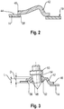
- the Fig. 2 shows sensor carrier sheet metal blank 42, generally designated 42, in abutment with an outer surface 44 of catalyst housing 19, here housing central region 14.
- the sensor support sheet blank 42 may be cut out, such as by punching or cutting, from a sheet stock, such as a sheet panel, first be provided substantially flat component and then in the desired shape for later use form, for example by pressing, bending or deep drawing, are transformed.
- the sensor carrier sheet metal blank 42 is provided with an edge region 46 shaped to rest on the catalyst housing 19 in such a way that this edge region 46 can rest on the outer surface 44 in the entire area surrounding the sensor opening 38.
- a sensor receiving opening 48 in the sensor carrier sheet blank 42 is produced by flow-hole forming.
- Flow-hole forming commonly known as “flow drilling” or “thermal friction drilling” is accomplished using a mandrel-like tool 50 heated to a high temperature and rotating about its longitudinal axis. The tool 50 is pressed against the sensor carrier sheet blank 42. In this case, in the area acted upon by the tool 50, the metal material of the sensor carrier sheet metal blank 42 is locally melted and to Side displaced.
- a material thickening 52 is formed on both sides of the sensor carrier sheet blank 42 so that the sensor receiving opening 48 passing through this material thickening 52 has an opening length L which is greater than the starting thickness D of the sheet metal material of the sensor carrier sheet blank 42.
- the tool 50 can be used to provide the sensor carrier sheet metal blank 42 in the region of the material thickening 52 with a substantially planar contact surface 54 for a sensor.
- the contact surface 54 is, as shown below, in the finished catalyst housing assembly 12 on the outside
- an internal thread 56 is cut into the sensor receiving opening 48 formed in the region of the material thickening 52.
- the internal thread 56 can be produced by a corresponding tool 58 immediately after the sensor receiving opening 38 is produced while the sensor carrier sheet blank 42 is still hot, or can be generated when the sensor carrier sheet metal blank 42 has already substantially cooled.
- the sensor carrier sheet metal blank 42 is substantially finished, so that a sensor carrier, generally designated 60, is provided.
- a sensor carrier generally designated 60
- This one is in a Fig. 5 illustrated operation with its edge region 46 on the outer surface 44 of the catalyst housing 19, in the illustrated example of the housing central region 14, fixed by welding.
- the edge portion 46 is placed on the substantially stepless, due to the tubular design of the housing central region 14, however, curved outer surface 44.
- fillet weld 62 surrounding the entire edge region 46 and thus bonding it to the catalyst housing 19 can be produced by fillet welding.
- a stable and in particular gas-tight connection between the sensor carrier 60 and the catalyst housing 19 is generated.
- a generally designated 64 sensor can then be screwed so that an external thread 66 provided thereon is in threaded engagement with the internal thread 56.
- the sensor 64 can be screwed in until a stop 68 formed thereon, for example as an external hexagon, abuts gas-tightly against the abutment surface 54 of the sensor carrier 60, possibly with intermediate storage of an annular sealing element.
- the various work steps described above can also be performed in a different chronological order.
- the sensor carrier sheet blank 42 after providing the sensor carrier sheet blank 42 with the desired shape, it can be set by welding to the catalyst housing 19. Subsequently, the sensor receiving opening 48 can then be provided by flow-hole forming, in which then the internal thread 56 is generated.
- the sensor receiving aperture 48 has been produced therein by flow-hole forming but before the female thread 56 is cut into the sensor receiving aperture 38, the sensor carrier metal blank 42 could be secured by welding to the catalyst housing 19.
- the Fig. 7 shows an alternative way of connecting the sensor carrier 60 or the sensor carrier sheet blank 42, depending on the sequence of operations, to the catalyst housing 19.
- the catalyst housing 19 for example, at the housing central region 14, in its peripheral contour of the peripheral contour of the sensor carrier 60th or the sensor carrier sheet blank 42 corresponding sensor support sink 70 is provided.
- the sensor carrier 60 or the sensor carrier sheet metal blank 42 is inserted into this sensor carrier depression 70, so that a gap remains between the edge region 46 and a wall 72 surrounding the sensor carrier depression 70.
- This space is a surrounding the entire edge region 46 and the gap substantially completely filling 1-weld 64, too introduced as a two-sided full seam introduced.
- the edge region 46 of the sensor carrier 60 or sensor carrier sheet metal blank 42 thus passes over the weld seam 74 into the outer surface 44 of the catalyst housing 19 substantially flush, that is, substantially without a step.
- the Fig. 8-10 show various ways of positioning a sensor carrier 60 on the catalyst housing 19.
- the in Fig. 8 Positioning shown corresponds essentially to those positioning, as they are for a sensor carrier in the structure of Fig. 1 is provided.
- the sensor opening 38 is provided in the housing central region 14, in particular in the region of the intermediate space 40 formed between the two catalyst units 20, 22.
- a sensor to be fixed to the sensor carrier 60 can engage in this intermediate space 40 or detect the gas composition or the temperature of the gas in this region ,
- the sensor carrier 60 is provided in a transition region 76 between the housing central region 14 and, for example, the housing end region 18.
- the sensor opening 38 is formed, for example, partially in the housing central region 14 and partially in the housing end region 18.
- the edge region 46 of the sensor carrier 60 or of the sensor carrier sheet metal blank 42 is fixed, for example, by fillet welding to the outer surface 44 of the catalyst housing 19.
- the sensor carrier 60 or the sensor carrier sheet metal blank 42 is completely provided, for example, on the housing end region 18.
- the sensor opening 38 is arranged completely in the conical region of the housing end region 18.
- a sensor carrier 60 By positioning a sensor carrier 60, it is advantageous to connect the various regions or components of the catalyst housing 19, such as the housing central region 14 and the housing end regions 16, 18, by welding or / and press-fitting, for example, before the sensor carrier 60 is attached to the transition region 76. at in the FIGS. 8 and 10 As shown, the sensor carrier 60 can be fixed to the respective area or component of the catalyst housing 19 before or after these areas or components of the catalyst housing 19 are assembled.
- a plurality of sensor carriers 60 may be provided on the catalyst housing 19.
- at least one sensor carrier 60 can be provided at each of the two housing end regions 16, 18, for example, to be able to detect the gas composition or gas temperature in the region upstream of the two catalyst units 20, 22 and in the region downstream of the catalyst units 20, 22, or in these Regions to be able to detect different measured variables.
- a plurality of sensor carriers 60 for example in the circumferential direction, to be provided successively on the housing central region 14.
- a plurality of sensor receiving openings for example two sensor receiving openings next to one another, can be provided in at least one of the sensor carriers, so that a plurality of sensors, for example configured for detecting different measured variables, can be carried on a single sensor carrier.
- the sensor carrier on the one hand and the sensor opening provided in association with it on the catalyst housing on the other hand are to be sized correspondingly larger.
- sensor carriers of different shapes can be provided on a catalyst housing in order to be able to ensure the suitable installation position, for example, depending on the installation location for the sensors to be arranged there.
Landscapes
- Engineering & Computer Science (AREA)
- Chemical & Material Sciences (AREA)
- Mechanical Engineering (AREA)
- Chemical Kinetics & Catalysis (AREA)
- Combustion & Propulsion (AREA)
- General Engineering & Computer Science (AREA)
- Analytical Chemistry (AREA)
- Health & Medical Sciences (AREA)
- Toxicology (AREA)
- Biomedical Technology (AREA)
- Environmental & Geological Engineering (AREA)
- General Chemical & Material Sciences (AREA)
- Oil, Petroleum & Natural Gas (AREA)
- Exhaust Gas After Treatment (AREA)
Abstract
Description
- Die vorliegende Erfindung betrifft ein Verfahren zur Herstellung einer Katalysatorgehäuseanordnung mit wenigstens einem Sensorträger für eine Abgasanlage eines Fahrzeugs.
- Die
US 2007/00178026 A1 Fig. 1 dargestellt und allgemein mit 10 bezeichnet. Sie umfasst eine Katalysatorgehäuseanordnung 12 mit einem rohrartig, also im Wesentlichen zylindrisch, beispielsweise mit kreisrundem Querschnitt, ausgebildeten Gehäusezentralbereich 14 und an beiden Endbereichen davon jeweils einem konischen Gehäuseendbereich 16,18. Ein Katalysatorgehäuse 19 der Katalysatorgehäuseanordnung 12 ist mit dem Gehäusezentralbereich 14 und den Gehäuseendbereichen 16, 18 beispielsweise aus Blechmaterial hergestellt. Im Innenraum des Katalysatorgehäuses 19 sind zwei Katalysatoreinheiten 20,22 vorgesehen. Jede Katalysatoreinheit 20,22 umfasst einen beispielsweise monolithisch ausgebildeten Katalysatorblock 24, 26 und eine diesen umgebende und durch Presspassung im Gehäusezentralbereich 14 lagernde Lagermatte 28,30. Über eine Öffnung 32 des Gehäuseendbereichs 16 können die von einer Brennkraftmaschine ausgestoßenen Abgase in die Katalysatoranordnung 10 eintreten. Über eine Öffnung 34 des Gehäuseendbereichs 18 können die Abgase aus der Katalysatoranordnung 10 austreten. - Am Gehäusezentralbereich 14 ist ein beispielsweise ringartiger Ansatz 36 vorgesehen, an welchem ein als Innengewindeelement ausgebildeter Sensorträger durch Verschweißung festgelegt werden kann. Ein Sensor, beispielsweise Gassensor, kann in den Sensorträger eingeschraubt werden und somit durch eine am Katalysatorgehäuse 19 vorgesehene Sensoröffnung 38 hindurch in einen zwischen den beiden Katalysatoreinheiten 20,22 gebildeten Zwischenraum 40 eingreifen und dort die Gaszusammensetzung, beispielsweise den Sauerstoffanteil oder den Stickoxidanteil, erfassen.
- Es ist die Aufgabe der vorliegenden Erfindung, ein Verfahren bereitzustellen, mit welchem in einfacher Weise eine eine zuverlässige Halterung wenigstens eines Sensors zulassende Katalysatorgehäuseanordnung für eine Abgasanlage eines Fahrzeugs hergestellt werden kann.
- Erfindungsgemäß wird diese Aufgabe gelöst durch ein Verfahren zur Herstellung einer Katalysatorgehäuseanordnung mit wenigstens einem Sensorträger für eine Abgasanlage eines Fahrzeugs, umfassend die Maßnahmen:
- a) Bereitstellen wenigstens eines Sensorträger-Blechrohlings,
- b) Bilden wenigstens einer Sensoraufnahmeöffnung in dem Sensorträger-Blechrohling durch Fließlochformen derart, dass eine Öffnungslänge größer ist als eine Materialstärke des Sensorträger-Blechrohlings vor Durchführung der Maßnahme b),
- c) Erzeugen eines Innengewindes in der wenigstens einen Sensoraufnahmeöffnung zum Bereitstellen eines Sensorträgers.
- Bei dem erfindungsgemäßen Verfahren wird durch das Bilden wenigstens einer Sensoraufnahmeöffnung durch Fließlochformen bei Erzeugung dieser Öffnung gleichzeitig auch eine Materialanhäufung in dem die Öffnung umgebenden Bereich erzeugt. Somit weist die Öffnung eine Öffnungslänge auf, die größer ist, als die Ausgangsdicke des Sensorträger-Blechrohlings, so dass Material zur Erzeugung eines ausreichend langen Innengewindes zur Verfügung gestellt ist.
- Das erfindungsgemäße Verfahren kann ferner folgende Maßnahmen umfassen:
- d) Bereitstellen eines Katalysatorgehäuses, vorzugsweise aus Blechmaterial, mit wenigstens einer Sensoröffnung,
- e) Festlegen wenigstens eines Sensorträger-Blechrohlings oder Sensorträgers an dem Katalysatorgehäuse vor der Maßnahme b) oder nach der Maßnahme c) oder nach der Maßnahme b) und vor der Maßnahme c).
- Bei dieser Vorgehensweise kann also der Sensorträger-Blechrohling noch vor dem Erzeugen einer Öffnung darin oder vor dem Einbringen des Innengewindes an der Katalysatorgehäuseanordnung festgelegt werden. Alternativ kann der fertiggestellte, also bereits mit Öffnung und Gewinde versehene Sensorträger an der Katalysatorgehäuseanordnung festgelegt werden. Das Katalysatorgehäuse kann dabei, je nach Art der Weiterbearbeitung, bereits als aus mehreren Teilen bzw. Bereichen zusammengesetztes Gehäuse bereitgestellt werden, oder kann mit den noch nicht zu einem Gehäuse zusammengesetzten Einzelteilen desselben zur weiteren Bearbeitung, insbesondere auch zur an Anbringung eines oder mehrerer Sensorträger oder Sensorträger-Blechrohlinge, bereitgestellt werden.
- Um eine stabile und gasdichte Anbindung eines Sensorträgers an das Katalysatorgehäuse gewährleisten zu können, wird vorgeschlagen, dass die Maßnahme e) das Festlegen durch Schweißen umfasst.
- Dabei kann beispielsweise vorgesehen sein, die Maßnahme e) das Auflegen wenigstens eines Sensorträger-Blechrohlings oder Sensorträgers auf eine Außenoberfläche des Katalysatorgehäuses und das Festlegen durch Kehlnahtschweißen umfasst. Alternativ kann für einen bündigen Übergang des Sensorträgers zur Außenoberfläche des Katalysatorgehäuses vorgesehen sein, dass die Maßnahme e) das Einlegen wenigstens eines Sensorträger-Blechrohlings oder Sensorträgers in eine an dem Katalysatorgehäuse im Bereich einer Sensoröffnung gebildete Sensorträgereinsenkung und das Festlegen durch I-Nahtschweißen umfasst.
- Die Maßnahme d) kann das Bereitstellen des Katalysatorgehäuses mit einem im Wesentlichen zylindrischen Gehäusezentralbereich und an wenigstens einem Ende des Gehäusezentralbereichs mit einem im Wesentlichen konischen Gehäuseendbereich umfassen, oder/und kann das Bereitstellen des Katalysatorgehäuses mit wenigstens einer Sensoröffnung in dem Gehäusezentralbereich umfassen. Insbesondere der Aufbau mit Blechmaterial ist einfach und kostengünstig durchzuführen und ermöglicht die stabile Anbindung eines oder mehrerer Sensorträger durch Verschweißung.
- Die Maßnahme d) kann ferner das Bereitstellen des Katalysatorgehäuses mit wenigstens einer Sensoröffnung in wenigstens einem Gehäuseendbereich umfassen, oder /und kann das Bereitstellen des Katalysatorgehäuses mit wenigstens einer Sensoröffnung in wenigstens einem Übergangsbereich von dem Gehäusezentralbereich zu einem Gehäuseendbereich umfassen.
- Die vorliegende Erfindung betrifft ferner eine Katalysatoranordnung für eine Abgasanlage eines Fahrzeugs, umfassend eine mit einem erfindungsgemäßen Verfahren hergestellte Katalysatorgehäuseanordnung.
- Vorzugsweise ist dabei an wenigstens einem an der Katalysatorgehäuseanordnung festgelegten Sensorträger wenigstens ein Sensor durch Gewindeeingriff getragen. Der Gewindeeingriff ermöglicht einerseits eine stabile, andererseits eine gasdichte Anbindung eines Sensors über den Sensorträger an die Katalysatorgehäuseanordnung.
- Wenigstens ein an der Katalysatorgehäuseanordnung getragener Sensor kann ein Gassensor, vorzugsweise O2-Sensor oder NOx-Sensor, sein, oder/und wenigstens ein an der Katalysatorgehäuseanordnung getragener Sensor kann ein Temperatursensor sein. Grundsätzlich können also an der Katalysatorgehäuseanordnung auch mehrere, beispielsweise verschiedene Sensoren an verschiedenen Positionen getragen sein, um somit umfassende Informationen über den Zustand bzw. die Zusammensetzung der Verbrennungsabgase bereitstellen zu können.
- In der Katalysatorgehäuseanordnung kann wenigstens eine Katalysatoreinheit getragen sein.
- Die vorliegende Erfindung wird nachfolgend mit Bezug auf die beiliegenden Figuren detailliert beschrieben. Es zeigt:
- Fig. 1
- eine Längsschnittansicht einer aus dem Stand der Technik bekannten Katalysatoranordnung;
- Fig. 2
- eine Schnittdarstellung eines Sensorträger-Blechrohlings;
- Fig. 3
- den Sensorträger-Blech Rohling der
Fig. 2 bei Durchführung eines Fließlochformungs-Vorgangs; - Fig. 4
- den Sensorträger-Blechrohling bei einem Gewindeschneide-Vorgang;
- Fig. 5
- einen Sensorträger an einem Katalysatorgehäuse mit einem daran getragenen Sensor;
- Fig. 6
- einen mit einer Kehlschweißnaht an einem Katalysatorgehäuse festgelegten Sensorträger;
- Fig. 7
- einen mit einer 1-Schweißnaht an einem Katalysatorgehäuse festgelegten Sensorträger;
- Fig. 8
- einen im Bereich eines Gehäusezentralbereichs festgelegten Sensorträger;
- Fig. 9
- einen in einem Übergangsbereich von einem Gehäusezentralbereich zu einem Gehäuseendbereich festgelegten Sensorträger;
- Fig. 10
- einen in einem Gehäuseendbereich festgelegten Sensorträger.
- Bevor im Folgenden detailliert ein Verfahren zur Herstellung einer Katalysatorgehäuseanordnung, insbesondere eines Sensorträgers dafür, eingegangen wird, ist darauf hinzuweisen, dass grundsätzlich der Aufbau einer so herzustellenden Katalysatorgehäuseanordnung bzw. einer diese umfassenden Katalysatoranordnung so beschaffen sein kann, wie in
Fig. 1 dargestellt und vorangehend mit Bezug aufFig. 1 beschrieben. Es wird daher im Folgenden unter Verwendung der eingangs bereits verwendeten Bezugszeichen auch im Kontext der vorliegenden Erfindung auf den grundsätzlichen Aufbau einer derartigen Katalysatorgehäuseanordnung bzw. Katalysatoranordnung Bezug genommen, wie sie inFig. 1 dargestellt ist. - Die
Fig. 2 zeigt einen allgemein mit 42 bezeichneten Sensorträger-Blechrohling 42 in Anlage an einer Außenoberfläche 44 des Katalysatorgehäuses 19, hier des Gehäusezentralbereichs 14. Der Sensorträger-Blechrohling 42 kann durch Heraustrennen, beispielsweise durch Ausstanzen oder Ausschneiden, aus einem Blechgrundmaterial, beispielsweise einer Blechtafel, als zunächst im Wesentlichen ebenes Bauteil bereitgestellt werden und dann in die für den späteren Einsatz gewünschte Form, z.B. durch Pressen, Biegen oder Tiefziehen, umgeformt werden. Dabei wird der Sensorträger-Blechrohling 42 mit einem zur Anlage am Katalysatorgehäuse 19 geformten Randbereich 46 derart bereitgestellt, dass dieser Randbereich 46 an der Außenoberfläche 44 im gesamten die Sensoröffnung 38 umgebenden Bereich anliegen kann. - In einem dann folgenden und
Fig. 3 veranschaulichten Arbeitsschritt wird durch Fließlochformen eine Sensoraufnahmeöffnung 48 im Sensorträger-Blechrohling 42 erzeugt. Das Fließlochformen, allgemein auch bekannt als "Flow Drilling" oder "Thermal Friction Drilling", wird unter Einsatz eines auf eine hohe Temperatur erwärmten und um seine Längsachse rotierenden, dornartigen Werkzeugs 50 durchgeführt. Das Werkzeug 50 wird gegen den Sensorträger-Blechrohling 42 gepresst. Dabei wird in dem durch das Werkzeug 50 beaufschlagten Bereich das Metallmaterial des Sensorträger-Blechrohlings 42 lokal aufgeschmolzen und zur Seite verdrängt. Es entsteht dabei in dem die Sensoraufnahmeöffnung 48 umgebenden Bereich eine Materialaufdickung 52 an beiden Seiten des Sensorträger-Blechrohlings 42, so dass die diese Materialaufdickung 52 durchsetzende Sensoraufnahmeöffnung 48 eine Öffnungslänge L aufweist, welche größer ist, als die Ausgangsdicke D des Blechmaterials des Sensorträger-Blechrohlings 42. Durch das Werkzeug 50 kann beim Fließlochformen der Sensorträger-Blechrohling 42 im Bereich der Materialaufdickung 52 auch mit einer im Wesentlichen planen Anlagefläche 54 für einen Sensor bereitgestellt werden. Die Anlagefläche 54 liegt, wie nachfolgend noch dargestellt, in der fertiggestellten Katalysatorgehäuseanordnung 12 an der Außenseite - In einem in
Fig. 4 veranschaulichten, dann folgenden Arbeitsschritt wird in die im Bereich der Materialaufdickung 52 gebildete Sensoraufnahmeöffnung 48 ein Innengewinde 56 geschnitten. Das Innengewinde 56 kann durch ein entsprechendes Werkzeug 58 unmittelbar nach dem Erzeugen der Sensoraufnahmeöffnung 38 im noch heißen Zustand des Sensorträger-Blechrohlings 42 erzeugt werden, oder kann dann erzeugt werden, wenn der Sensorträger-Blechrohling 42 bereits im Wesentlichen abgekühlt ist. - Nach dem Erzeugen des Innengewindes 56 ist der Sensorträger-Blechrohling 42 im Wesentlichen fertig bearbeitet, so dass ein allgemein mit 60 bezeichneter Sensorträger bereitgestellt ist. Dieser wird in einem in
Fig. 5 veranschaulichten Arbeitsschritt mit seinem Randbereich 46 an der Außenoberfläche 44 des Katalysatorgehäuses 19, im dargestellten Beispiel des Gehäusezentralbereichs 14, durch Verschweißung festgelegt. Bei der in denFig. 5 und6 dargestellten Art der Festlegung durch Verschweißen wird der Randbereich 46 auf die im Wesentlichen stufenfreie, aufgrund der rohrartigen Ausgestaltung des Gehäusezentralbereich 14 jedoch gekrümmte Außenoberfläche 44 aufgelegt. In dem winkeligen Übergangsbereich zwischen dem Randbereich 46 und der Außenoberfläche 44 kann durch Kehlnahtschweißen eine den gesamten Randbereich 46 umgebende und diesen somit an das Katalysatorgehäuse 19 anbindende Schweißnaht 62 erzeugt werden. Somit wird eine stabile und insbesondere gasdichte Verbindung zwischen dem Sensorträger 60 und dem Katalysatorgehäuse 19 erzeugt. - In den Sensorträger 60 kann dann ein allgemein mit 64 bezeichneter Sensor eingeschraubt werden, so dass ein daran vorgesehenes Außengewinde 66 in Gewindeeingriff mit dem Innengewinde 56 ist. Der Sensor 64 kann so weit eingeschraubt werden, bis ein daran beispielsweise als Außensechskant ausgebildeter Anschlag 68 an der Anlagefläche 54 des Sensorträgers 60, gegebenenfalls unter Zwischenlagerung eines ringartigen Dichtungselement, gasdicht anliegt.
- Bei der Herstellung bzw. Festlegung des Sensorträgers 60 können die verschiedenen vorangehend beschriebenen Arbeitsschritte auch in anderer zeitlicher Abfolge durchgeführt werden. So kann beispielsweise nach Bereitstellung des Sensorträger-Blechrohlings 42 mit der gewünschten Form dieser durch Verschweißung am Katalysatorgehäuse 19 festgelegt werden. Nachfolgend kann dann durch Fließlochformen die Sensoraufnahmeöffnung 48 bereitgestellt werden, in welcher dann das Innengewinde 56 erzeugt wird. Alternativ könnte der Sensorträger-Blechrohling 42 dann, wenn in diesem durch Fließlochformen die Sensoraufnahmeöffnung 48 erzeugt worden ist, jedoch bevor das Innengewinde 56 in die Sensoraufnahmeöffnung 38 geschnitten wird, durch Verschweißung am Katalysatorgehäuse 19 festgelegt werden.
- Die
Fig. 7 zeigt eine alternative Art der Anbindung des Sensorträgers 60 bzw. des Sensorträger-Blechrohlings 42, je nach Abfolge der Arbeitsschritte, an das Katalysatorgehäuse 19. Bei dieser Variante ist am Katalysatorgehäuse 19, beispielsweise am Gehäusezentralbereich 14, eine in ihrer Umfangskontur der Umfangskontur des Sensorträgers 60 bzw. des Sensorträger-Blechrohlings 42 entsprechende Sensorträgereinsenkung 70 vorgesehen. In diese Sensorträgereinsenkung 70 wird der Sensorträger 60 bzw. der Sensorträger-Blechrohling 42 eingelegt, so dass zwischen dem Randbereich 46 und einer die Sensorträgereinsenkung 70 umgebenden Wandung 72 ein Zwischenraum verbleibt. In diesen Zwischenraum wird eine den gesamten Randbereich 46 umgebende und den Zwischenraum im Wesentlichen vollständig ausfüllende 1-Schweißnaht 64, auch als zweiseitige Vollnaht bezeichnet, eingebracht. Der Randbereich 46 des Sensorträgers 60 bzw. Sensorträger-Blechrohlings 42 geht somit im Wesentlichen bündig, also im Wesentlichen ohne Stufe, über die Schweißnaht 74 in die Außenoberfläche 44 des Katalysatorgehäuses 19 über. - Die
Fig. 8-10 zeigen verschiedene Arten der Positionierung eines Sensorträgers 60 am Katalysatorgehäuse 19. Die inFig. 8 dargestellte Positionierung entspricht im Wesentlichen auch derjenigen Positionierung, wie sie für einen Sensorträger bei dem Aufbau derFig. 1 vorgesehen ist. Die Sensoröffnung 38 ist im Gehäusezentralbereich 14 vorgesehen, insbesondere im Bereich des zwischen den beiden Katalysatoreinheiten 20,22 gebildeten Zwischenraums 40. Ein an dem Sensorträger 60 festzulegender Sensor kann in diesen Zwischenraum 40 eingreifen bzw. die Gaszusammensetzung oder die Temperatur des Gases in diesem Bereich erfassen. - Bei der Ausgestaltungsform gemäß
Fig. 9 ist der Sensorträger 60 in einem Übergangsbereich 76 zwischen dem Gehäusezentralbereich 14 und beispielsweise dem Gehäuseendbereich 18 vorgesehen. Bei dieser Variante ist die Sensoröffnung 38 beispielsweise teilweise im Gehäusezentralbereich 14 und teilweise im Gehäuseendbereich 18 ausgebildet. Der Randbereich 46 des Sensorträgers 60 bzw. des Sensorträger-Blechrohlings 42 ist beispielsweise durch Kehlnahtschweißen an der Außenoberfläche 44 des Katalysatorgehäuses 19 festgelegt. - Bei der in
Fig. 10 dargestellten Ausgestaltungsvariante ist der Sensorträger 60 bzw. der Sensorträger-Blechrohling 42 vollständig beispielsweise am Gehäuseendbereich 18 vorgesehen. Die Sensoröffnung 38 ist vollständig im konischen Bereich des Gehäuseendbereichs 18 angeordnet. - Bei der in
Fig. 9 veranschaulichen Positionierung eines Sensorträgers 60 ist es vorteilhaft, die verschiedenen Bereiche bzw. Komponenten des Katalysatorgehäuses 19 also den Gehäusezentralbereich 14 und die Gehäuseendbereiche 16,18, beispielsweise durch Verschweißung oder/und Presspassung miteinander zu verbinden, bevor der Sensorträger 60 am Übergangsbereich 76 angebracht wird. Bei den in denFig. 8 und 10 dargestellten Positionierungen kann der Sensorträger 60 an dem jeweiligen Bereich bzw. der jeweiligen Komponente des Katalysatorgehäuses 19 festgelegt werden, bevor oder nachdem diese Bereiche bzw. Komponenten des Katalysatorgehäuses 19 zusammengesetzt werden. - Es ist darauf hinzuweisen, dass an dem Katalysatorgehäuse 19 mehrere Sensorträger 60 vorgesehen sein können. So kann beispielsweise an jedem der beiden Gehäuseendbereiche 16, 18 jeweils mindestens ein Sensorträger 60 vorgesehen sein, um beispielsweise die Gaszusammensetzung oder Gastemperatur im Bereich stromaufwärts der beiden Katalysatoreinheiten 20, 22 und im Bereich stromabwärts der Katalysatoreinheiten 20, 22 erfassen zu können, oder in diesen Bereichen jeweils unterschiedliche Meßgrößen erfassen zu können. Alternativ oder zusätzlich können auch am Gehäusezentralbereich 14 mehrere Sensorträger 60, beispielsweise in Umfangsrichtung aufeinanderfolgend vorgesehen sein.
- Ferner kann bei zumindest einem der Sensorträger einen Mehrzahl von Sensoraufnahmeöffnungen, beispielsweise zwei Sensoraufnahmeöffnungen nebeneinander, vorgesehen sein, so dass an einem einzigen Sensorträger mehrere Sensoren, diese beispielsweise ausgestaltet zur Erfassung verschiedener Messgrößen, getragen werden können. In diesem Falle sind der Sensorträger einerseits und die in Zuordnung dazu am Katalysatorgehäuse vorgesehene Sensoröffnung andererseits entsprechend größer zu dimensionieren. Weiter können an einem Katalysatorgehäuse Sensorträger verschiedener Formgebung vorgesehen sein, um beispielsweise abhängig vom Einbauort für die dort jeweils anzuordnenden Sensoren die geeignete Einbauposition gewährleisten zu können.
Claims (13)
- Verfahren zur Herstellung einer Katalysatorgehäuseanordnung (12) mit wenigstens einem Sensorträger (60) für eine Abgasanlage eines Fahrzeugs, umfassend die Maßnahmen:a) Bereitstellen wenigstens eines Sensorträger-Blechrohlings (42),b) Bilden wenigstens einer Sensoraufnahmeöffnung (48) in dem Sensorträger-Blechrohling (42) durch Fließlochformen derart, dass eine Öffnungslänge (L) größer ist als eine Materialstärke (D) des Sensorträger-Blechrohlings (42) vor Durchführung der Maßnahme b),c) Erzeugen eines Innengewindes (56) in der wenigstens einen Sensoraufnahmeöffnung (48) zum Bereitstellen eines Sensorträgers (60).
- Verfahren nach Anspruch 1, gekennzeichnet durch die Maßnahmen:d) Bereitstellen eines Katalysatorgehäuses (19), vorzugsweise aus Blechmaterial, mit wenigstens einer Sensoröffnung (38),e) Festlegen wenigstens eines Sensorträger-Blechrohlings (42) oder Sensorträgers (60) an dem Katalysatorgehäuse (19) vor der Maßnahme b) oder nach der Maßnahme c) oder nach der Maßnahme b) und vor der Maßnahme c).
- Verfahren nach Anspruch 2, dadurch gekennzeichnet, dass die Maßnahme e) das Festlegen durch Schweißen umfasst.
- Verfahren nach Anspruch 3, dadurch gekennzeichnet, dass die Maßnahme e) das Auflegen wenigstens eines Sensorträger-Blechrohlings (42) oder Sensorträgers (60) auf eine Außenoberfläche (44) des Katalysatorgehäuses (19) und das Festlegen durch Kehlnahtschweißen umfasst.
- Verfahren Anspruch 3 oder 4, dadurch gekennzeichnet, dass die Maßnahme e) das Einlegen wenigstens eines Sensorträger-Blechrohlings (42) oder Sensorträgers (60) in eine an dem Katalysatorgehäuse (19) im Bereich einer Sensoröffnung (38) gebildete Sensorträgereinsenkung (70) und das Festlegen durch I-Nahtschweißen umfasst.
- Verfahren nach einem der Ansprüche 2-4, dadurch gekennzeichnet, dass die Maßnahme d) das Bereitstellen des Katalysatorgehäuses (19) mit einem im Wesentlichen zylindrischen Gehäusezentralbereich (14) und an wenigstens einem Ende des Gehäusezentralbereichs (14) mit einem im Wesentlichen konischen Gehäuseendbereich (16, 18) umfasst.
- Verfahren nach Anspruch 6, dadurch gekennzeichnet, dass die Maßnahme d) das Bereitstellen des Katalysatorgehäuses (19) mit wenigstens einer Sensoröffnung (38) in dem Gehäusezentralbereich (14) umfasst.
- Verfahren Anspruch 6 oder 7, dadurch gekennzeichnet, dass die Maßnahme d) das Bereitstellen des Katalysatorgehäuses (19) mit wenigstens einer Sensoröffnung (38) in wenigstens einem Gehäuseendbereich (16, 18) umfasst.
- Verfahren einen der Ansprüche 6-8, dadurch gekennzeichnet, dass die Maßnahme d) das Bereitstellen des Katalysatorgehäuses (19) mit wenigstens einer Sensoröffnung (38) in wenigstens einem Übergangsbereich (76) von dem Gehäusezentralbereich (14) zu einem Gehäuseendbereich (16, 18) umfasst.
- Katalysatoranordnung für eine Abgasanlage eines Fahrzeugs, umfassend eine mit einem Verfahren nach einem der vorangehenden Ansprüche hergestellte Katalysatorgehäuseanordnung (12).
- Katalysatoranordnung nach Anspruch 10, dadurch gekennzeichnet, an wenigstens einem an der Katalysatorgehäuseanordnung (12) vorgesehenen Sensorträger (60) wenigstens ein Sensor (64) durch Gewindeeingriff getragen ist.
- Katalysatoranordnung nach Anspruch 10 oder 11, dadurch gekennzeichnet, dass wenigstens ein an der Katalysatorgehäuseanordnung (12) getragener Sensor (64) ein Gassensor, vorzugsweise O2-Sensor oder NOx-Sensor, ist, oder/und dass wenigstens ein an der Katalysatorgehäuseanordnung (12) getragener Sensor (64) ein Temperatursensor ist.
- Katalysatoranordnung nach einem der Ansprüche 10-12, dadurch gekennzeichnet, dass in der Katalysatorgehäuseanordnung (12) wenigstens eine Katalysatoreinheit (20, 22) getragen ist.
Applications Claiming Priority (1)
| Application Number | Priority Date | Filing Date | Title |
|---|---|---|---|
| DE102015121110.6A DE102015121110A1 (de) | 2015-12-04 | 2015-12-04 | Verfahren zur Herstellung einer Katalysatorgehäuseanordnung mit wenigstens einem Sensorträger für eine Abgasanlage eines Fahrzeugs |
Publications (3)
| Publication Number | Publication Date |
|---|---|
| EP3176398A2 true EP3176398A2 (de) | 2017-06-07 |
| EP3176398A3 EP3176398A3 (de) | 2017-06-14 |
| EP3176398B1 EP3176398B1 (de) | 2019-01-30 |
Family
ID=57482190
Family Applications (1)
| Application Number | Title | Priority Date | Filing Date |
|---|---|---|---|
| EP16201378.3A Active EP3176398B1 (de) | 2015-12-04 | 2016-11-30 | Verfahren zur herstellung einer katalysatorgehäuseanordnung mit wenigstens einem sensorträger für eine abgasanlage eines fahrzeugs |
Country Status (4)
| Country | Link |
|---|---|
| US (1) | US10385755B2 (de) |
| EP (1) | EP3176398B1 (de) |
| CN (1) | CN106826105B (de) |
| DE (1) | DE102015121110A1 (de) |
Cited By (1)
| Publication number | Priority date | Publication date | Assignee | Title |
|---|---|---|---|---|
| CN112958885A (zh) * | 2021-02-04 | 2021-06-15 | 中国第一汽车股份有限公司 | 一种氧传感器底座的焊接方法 |
Families Citing this family (14)
| Publication number | Priority date | Publication date | Assignee | Title |
|---|---|---|---|---|
| DE102015121110A1 (de) * | 2015-12-04 | 2017-06-08 | Eberspächer Exhaust Technology GmbH & Co. KG | Verfahren zur Herstellung einer Katalysatorgehäuseanordnung mit wenigstens einem Sensorträger für eine Abgasanlage eines Fahrzeugs |
| DE102017112356A1 (de) * | 2017-06-06 | 2018-12-06 | Dr. Ing. H.C. F. Porsche Aktiengesellschaft | Abgasnachbehandlungseinrichtung für einen Verbrennungsmotor und entsprechendes Kraftfahrzeug |
| DE102017128607A1 (de) | 2017-12-01 | 2019-06-06 | Eberspächer Exhaust Technology GmbH & Co. KG | Gehäuseanschlusselement |
| KR102529517B1 (ko) * | 2018-06-15 | 2023-05-04 | 현대자동차주식회사 | 터보차저 차량의 배기 장치 |
| CN109607442B (zh) * | 2018-11-07 | 2021-06-01 | 中国航空工业集团公司西安飞机设计研究所 | 一种飞机上的千斤顶支座及其设计方法 |
| CN109648264A (zh) * | 2018-12-25 | 2019-04-19 | 上海安皑迪实业有限公司 | 一种金属基材上杆连接的加工工艺 |
| DE102019100267A1 (de) * | 2019-01-08 | 2020-07-09 | Eberspächer Exhaust Technology GmbH & Co. KG | Mischer für eine Abgasanlage einer Brennkraftmaschine |
| DE102019101678A1 (de) * | 2019-01-24 | 2020-07-30 | Eberspächer Exhaust Technology GmbH & Co. KG | Mischer |
| DE102019001246A1 (de) * | 2019-02-20 | 2020-08-20 | Eberspächer Exhaust Technology GmbH & Co. KG | Sondenstutzen für eine Abgasanlage |
| US11118496B2 (en) * | 2019-07-18 | 2021-09-14 | Tenneco Automotive Operating Company Inc. | Exhaust treatment device with multiple substrates |
| CN110821626A (zh) * | 2019-12-18 | 2020-02-21 | 上海天纳克排气系统有限公司 | 传感器座 |
| US11084085B1 (en) * | 2020-10-23 | 2021-08-10 | Ford Global Technologies, Llc | Vehicle component joining method |
| CN114718710A (zh) * | 2021-01-04 | 2022-07-08 | 佛吉亚排气控制技术开发(上海)有限公司 | 传感器安装座、传感器组件以及排气系统 |
| WO2025203631A1 (ja) * | 2024-03-29 | 2025-10-02 | 本田技研工業株式会社 | 排気装置 |
Citations (1)
| Publication number | Priority date | Publication date | Assignee | Title |
|---|---|---|---|---|
| US20070178026A1 (en) | 2006-02-01 | 2007-08-02 | Roth Gregory T | Exhaust treatment device with sensor and method of making |
Family Cites Families (11)
| Publication number | Priority date | Publication date | Assignee | Title |
|---|---|---|---|---|
| JP3329358B2 (ja) * | 1995-04-24 | 2002-09-30 | カルソニックカンセイ株式会社 | 排ガス浄化装置 |
| FR2762045B1 (fr) * | 1997-04-10 | 1999-06-04 | Renault | Dispositif d'echappement pour moteur a combustion interne et son procede de fabrication |
| DE19811569A1 (de) * | 1998-03-17 | 1999-09-23 | Volkswagen Ag | Verfahren zum Herstellen einer Abgasanlage einer Brennkraftmaschine |
| US8110152B2 (en) * | 2001-07-12 | 2012-02-07 | Katcon Global S.A. | Gas sensor mounting boss and method of making |
| US7279140B2 (en) * | 2001-07-12 | 2007-10-09 | Delphi Technologies, Inc. | Catalytic converter with integral oxygen sensor |
| US7774936B2 (en) * | 2004-08-02 | 2010-08-17 | Emcon Technologies Llc | Catalytic converter and associated method of assembly |
| DE102007042281A1 (de) * | 2007-09-06 | 2009-03-12 | J. Eberspächer GmbH & Co. KG | Verfahren zum Anbringen einer Sonde an einer Abgasbehandlungseinrichtung |
| US8795598B2 (en) * | 2007-09-27 | 2014-08-05 | Katcon Global S.A. | Exhaust treatment device with independent catalyst supports |
| DE102011018748B3 (de) * | 2011-04-27 | 2012-07-26 | Audi Ag | Verfahren zum Herstellen von Anschlussbuchsen und zugehöriges Bauteil |
| CN202866944U (zh) * | 2012-07-30 | 2013-04-10 | 刘光文 | 无焊接发动机废气净化催化器 |
| DE102015121110A1 (de) * | 2015-12-04 | 2017-06-08 | Eberspächer Exhaust Technology GmbH & Co. KG | Verfahren zur Herstellung einer Katalysatorgehäuseanordnung mit wenigstens einem Sensorträger für eine Abgasanlage eines Fahrzeugs |
-
2015
- 2015-12-04 DE DE102015121110.6A patent/DE102015121110A1/de not_active Withdrawn
-
2016
- 2016-11-30 EP EP16201378.3A patent/EP3176398B1/de active Active
- 2016-12-02 CN CN201611099775.4A patent/CN106826105B/zh active Active
- 2016-12-02 US US15/367,668 patent/US10385755B2/en active Active
Patent Citations (1)
| Publication number | Priority date | Publication date | Assignee | Title |
|---|---|---|---|---|
| US20070178026A1 (en) | 2006-02-01 | 2007-08-02 | Roth Gregory T | Exhaust treatment device with sensor and method of making |
Cited By (1)
| Publication number | Priority date | Publication date | Assignee | Title |
|---|---|---|---|---|
| CN112958885A (zh) * | 2021-02-04 | 2021-06-15 | 中国第一汽车股份有限公司 | 一种氧传感器底座的焊接方法 |
Also Published As
| Publication number | Publication date |
|---|---|
| CN106826105B (zh) | 2020-04-07 |
| EP3176398A3 (de) | 2017-06-14 |
| CN106826105A (zh) | 2017-06-13 |
| EP3176398B1 (de) | 2019-01-30 |
| US20170159537A1 (en) | 2017-06-08 |
| DE102015121110A1 (de) | 2017-06-08 |
| US10385755B2 (en) | 2019-08-20 |
Similar Documents
| Publication | Publication Date | Title |
|---|---|---|
| EP3176398B1 (de) | Verfahren zur herstellung einer katalysatorgehäuseanordnung mit wenigstens einem sensorträger für eine abgasanlage eines fahrzeugs | |
| EP3134670B1 (de) | Steckerbaugruppe | |
| DE19614656A1 (de) | Verfahren zum Erhöhen der Wandungsstärke bei Hohlprofilen | |
| EP3580487B1 (de) | Steckerbaugruppe zur verwendung in einem fahrzeug | |
| EP3924115B1 (de) | Umformwerkzeug und umformverfahren zur herstellung einer überdrucksollbruchstelle in einem batteriedeckel | |
| EP3110587B1 (de) | Lötspitzenbefestigungssystem | |
| DE7935982U1 (de) | Wälzlagerkäfig | |
| DE112016002129B4 (de) | Verfahren und Vorrichtung zur Größenanpassung einer Bauteilhülle mit mindestens zwei unterschiedlichen Durchmessern | |
| DE10347253B4 (de) | Verfahren zur Herstellung eines Lagerträgers zur Aufnahme wenigstens eines Lagers | |
| DE102009013881A1 (de) | Vorrichtung mit einem Beschlag und einer Adapterplatte sowie Verfahren zur Herstellung einer solchen Vorrichtung | |
| DE10105841C2 (de) | Abgasleitung mit Luftspaltisolierung für eine Brennkraftmaschine | |
| DE202009008997U1 (de) | Sondenstutzen | |
| EP3530898A1 (de) | Abgasanlage | |
| DE2220657A1 (de) | Anordnung zum befestigen zweier bauteile | |
| DE19543603A1 (de) | Anordnung zur Schweißverbindung eines Grundelementes mit einem anderen Bauteil aus Stahl | |
| DE102005007716A1 (de) | Sitzhöhenverstellung | |
| DE4444857C1 (de) | Verfahren und Vorrichtung zur Herstellung mindestens einer Öffnung in der Wandung eines rohrartigen Teils | |
| DE102015120509A1 (de) | Schlauchschelle | |
| DE2548853B2 (de) | Vorrichtung zur Herstellung von metallenen Ringrohlingen | |
| DE19748623A1 (de) | Preßverbindung | |
| EP3172416B1 (de) | Katalysatoreinheit und verfahren zum herstellen derselben | |
| WO2003004832A1 (de) | Befestigungsanordnung für einen schneidmeissel | |
| DE102015209531B4 (de) | Verfahren zum Herstellen einer Bauteilverbindung | |
| DE3201263C2 (de) | Verfahren und Vorrichtung zur Herstellung eines Dichtungsringaggregates | |
| DE19818733B4 (de) | Verfahren zum Herstellen eines Verbundrohres sowie Verbundrohr |
Legal Events
| Date | Code | Title | Description |
|---|---|---|---|
| PUAL | Search report despatched |
Free format text: ORIGINAL CODE: 0009013 |
|
| AK | Designated contracting states |
Kind code of ref document: A2 Designated state(s): AL AT BE BG CH CY CZ DE DK EE ES FI FR GB GR HR HU IE IS IT LI LT LU LV MC MK MT NL NO PL PT RO RS SE SI SK SM TR |
|
| AX | Request for extension of the european patent |
Extension state: BA ME |
|
| AK | Designated contracting states |
Kind code of ref document: A3 Designated state(s): AL AT BE BG CH CY CZ DE DK EE ES FI FR GB GR HR HU IE IS IT LI LT LU LV MC MK MT NL NO PL PT RO RS SE SI SK SM TR |
|
| AX | Request for extension of the european patent |
Extension state: BA ME |
|
| RIC1 | Information provided on ipc code assigned before grant |
Ipc: B21J 5/06 20060101ALI20170511BHEP Ipc: F01N 13/18 20100101ALI20170511BHEP Ipc: F01N 13/00 20100101AFI20170511BHEP |
|
| PUAI | Public reference made under article 153(3) epc to a published international application that has entered the european phase |
Free format text: ORIGINAL CODE: 0009012 |
|
| STAA | Information on the status of an ep patent application or granted ep patent |
Free format text: STATUS: THE APPLICATION HAS BEEN PUBLISHED |
|
| STAA | Information on the status of an ep patent application or granted ep patent |
Free format text: STATUS: REQUEST FOR EXAMINATION WAS MADE |
|
| 17P | Request for examination filed |
Effective date: 20170904 |
|
| RBV | Designated contracting states (corrected) |
Designated state(s): AL AT BE BG CH CY CZ DE DK EE ES FI FR GB GR HR HU IE IS IT LI LT LU LV MC MK MT NL NO PL PT RO RS SE SI SK SM TR |
|
| STAA | Information on the status of an ep patent application or granted ep patent |
Free format text: STATUS: EXAMINATION IS IN PROGRESS |
|
| 17Q | First examination report despatched |
Effective date: 20180312 |
|
| GRAP | Despatch of communication of intention to grant a patent |
Free format text: ORIGINAL CODE: EPIDOSNIGR1 |
|
| STAA | Information on the status of an ep patent application or granted ep patent |
Free format text: STATUS: GRANT OF PATENT IS INTENDED |
|
| RIC1 | Information provided on ipc code assigned before grant |
Ipc: B21J 5/06 20060101ALI20180912BHEP Ipc: F01N 13/00 20100101AFI20180912BHEP Ipc: F01N 3/28 20060101ALI20180912BHEP Ipc: B23K 31/02 20060101ALI20180912BHEP Ipc: B01D 53/94 20060101ALI20180912BHEP Ipc: F01N 13/18 20100101ALI20180912BHEP |
|
| INTG | Intention to grant announced |
Effective date: 20180927 |
|
| GRAS | Grant fee paid |
Free format text: ORIGINAL CODE: EPIDOSNIGR3 |
|
| GRAA | (expected) grant |
Free format text: ORIGINAL CODE: 0009210 |
|
| STAA | Information on the status of an ep patent application or granted ep patent |
Free format text: STATUS: THE PATENT HAS BEEN GRANTED |
|
| RAP1 | Party data changed (applicant data changed or rights of an application transferred) |
Owner name: EBERSPAECHER EXHAUST TECHNOLOGY GMBH & CO. KG Owner name: EBERSPAECHER TECNOLOGIA DE EXAUSTAO LTDA. |
|
| AK | Designated contracting states |
Kind code of ref document: B1 Designated state(s): AL AT BE BG CH CY CZ DE DK EE ES FI FR GB GR HR HU IE IS IT LI LT LU LV MC MK MT NL NO PL PT RO RS SE SI SK SM TR |
|
| REG | Reference to a national code |
Ref country code: GB Ref legal event code: FG4D Free format text: NOT ENGLISH |
|
| REG | Reference to a national code |
Ref country code: CH Ref legal event code: EP |
|
| REG | Reference to a national code |
Ref country code: AT Ref legal event code: REF Ref document number: 1093453 Country of ref document: AT Kind code of ref document: T Effective date: 20190215 |
|
| RAP2 | Party data changed (patent owner data changed or rights of a patent transferred) |
Owner name: EBERSPAECHER EXHAUST TECHNOLOGY GMBH & CO. KG Owner name: EBERSPAECHER TECNOLOGIA DE EXAUSTAO LTDA. |
|
| REG | Reference to a national code |
Ref country code: IE Ref legal event code: FG4D Free format text: LANGUAGE OF EP DOCUMENT: GERMAN |
|
| REG | Reference to a national code |
Ref country code: DE Ref legal event code: R096 Ref document number: 502016003269 Country of ref document: DE |
|
| REG | Reference to a national code |
Ref country code: SE Ref legal event code: TRGR |
|
| REG | Reference to a national code |
Ref country code: LT Ref legal event code: MG4D |
|
| REG | Reference to a national code |
Ref country code: NL Ref legal event code: MP Effective date: 20190130 |
|
| PG25 | Lapsed in a contracting state [announced via postgrant information from national office to epo] |
Ref country code: ES Free format text: LAPSE BECAUSE OF FAILURE TO SUBMIT A TRANSLATION OF THE DESCRIPTION OR TO PAY THE FEE WITHIN THE PRESCRIBED TIME-LIMIT Effective date: 20190130 Ref country code: NL Free format text: LAPSE BECAUSE OF FAILURE TO SUBMIT A TRANSLATION OF THE DESCRIPTION OR TO PAY THE FEE WITHIN THE PRESCRIBED TIME-LIMIT Effective date: 20190130 Ref country code: PT Free format text: LAPSE BECAUSE OF FAILURE TO SUBMIT A TRANSLATION OF THE DESCRIPTION OR TO PAY THE FEE WITHIN THE PRESCRIBED TIME-LIMIT Effective date: 20190530 Ref country code: PL Free format text: LAPSE BECAUSE OF FAILURE TO SUBMIT A TRANSLATION OF THE DESCRIPTION OR TO PAY THE FEE WITHIN THE PRESCRIBED TIME-LIMIT Effective date: 20190130 Ref country code: LT Free format text: LAPSE BECAUSE OF FAILURE TO SUBMIT A TRANSLATION OF THE DESCRIPTION OR TO PAY THE FEE WITHIN THE PRESCRIBED TIME-LIMIT Effective date: 20190130 Ref country code: FI Free format text: LAPSE BECAUSE OF FAILURE TO SUBMIT A TRANSLATION OF THE DESCRIPTION OR TO PAY THE FEE WITHIN THE PRESCRIBED TIME-LIMIT Effective date: 20190130 Ref country code: NO Free format text: LAPSE BECAUSE OF FAILURE TO SUBMIT A TRANSLATION OF THE DESCRIPTION OR TO PAY THE FEE WITHIN THE PRESCRIBED TIME-LIMIT Effective date: 20190430 |
|
| PG25 | Lapsed in a contracting state [announced via postgrant information from national office to epo] |
Ref country code: IS Free format text: LAPSE BECAUSE OF FAILURE TO SUBMIT A TRANSLATION OF THE DESCRIPTION OR TO PAY THE FEE WITHIN THE PRESCRIBED TIME-LIMIT Effective date: 20190530 Ref country code: BG Free format text: LAPSE BECAUSE OF FAILURE TO SUBMIT A TRANSLATION OF THE DESCRIPTION OR TO PAY THE FEE WITHIN THE PRESCRIBED TIME-LIMIT Effective date: 20190430 Ref country code: LV Free format text: LAPSE BECAUSE OF FAILURE TO SUBMIT A TRANSLATION OF THE DESCRIPTION OR TO PAY THE FEE WITHIN THE PRESCRIBED TIME-LIMIT Effective date: 20190130 Ref country code: RS Free format text: LAPSE BECAUSE OF FAILURE TO SUBMIT A TRANSLATION OF THE DESCRIPTION OR TO PAY THE FEE WITHIN THE PRESCRIBED TIME-LIMIT Effective date: 20190130 Ref country code: GR Free format text: LAPSE BECAUSE OF FAILURE TO SUBMIT A TRANSLATION OF THE DESCRIPTION OR TO PAY THE FEE WITHIN THE PRESCRIBED TIME-LIMIT Effective date: 20190501 Ref country code: HR Free format text: LAPSE BECAUSE OF FAILURE TO SUBMIT A TRANSLATION OF THE DESCRIPTION OR TO PAY THE FEE WITHIN THE PRESCRIBED TIME-LIMIT Effective date: 20190130 |
|
| PG25 | Lapsed in a contracting state [announced via postgrant information from national office to epo] |
Ref country code: CZ Free format text: LAPSE BECAUSE OF FAILURE TO SUBMIT A TRANSLATION OF THE DESCRIPTION OR TO PAY THE FEE WITHIN THE PRESCRIBED TIME-LIMIT Effective date: 20190130 Ref country code: IT Free format text: LAPSE BECAUSE OF FAILURE TO SUBMIT A TRANSLATION OF THE DESCRIPTION OR TO PAY THE FEE WITHIN THE PRESCRIBED TIME-LIMIT Effective date: 20190130 Ref country code: SK Free format text: LAPSE BECAUSE OF FAILURE TO SUBMIT A TRANSLATION OF THE DESCRIPTION OR TO PAY THE FEE WITHIN THE PRESCRIBED TIME-LIMIT Effective date: 20190130 Ref country code: AL Free format text: LAPSE BECAUSE OF FAILURE TO SUBMIT A TRANSLATION OF THE DESCRIPTION OR TO PAY THE FEE WITHIN THE PRESCRIBED TIME-LIMIT Effective date: 20190130 Ref country code: DK Free format text: LAPSE BECAUSE OF FAILURE TO SUBMIT A TRANSLATION OF THE DESCRIPTION OR TO PAY THE FEE WITHIN THE PRESCRIBED TIME-LIMIT Effective date: 20190130 Ref country code: EE Free format text: LAPSE BECAUSE OF FAILURE TO SUBMIT A TRANSLATION OF THE DESCRIPTION OR TO PAY THE FEE WITHIN THE PRESCRIBED TIME-LIMIT Effective date: 20190130 Ref country code: RO Free format text: LAPSE BECAUSE OF FAILURE TO SUBMIT A TRANSLATION OF THE DESCRIPTION OR TO PAY THE FEE WITHIN THE PRESCRIBED TIME-LIMIT Effective date: 20190130 |
|
| REG | Reference to a national code |
Ref country code: DE Ref legal event code: R097 Ref document number: 502016003269 Country of ref document: DE |
|
| PG25 | Lapsed in a contracting state [announced via postgrant information from national office to epo] |
Ref country code: SM Free format text: LAPSE BECAUSE OF FAILURE TO SUBMIT A TRANSLATION OF THE DESCRIPTION OR TO PAY THE FEE WITHIN THE PRESCRIBED TIME-LIMIT Effective date: 20190130 |
|
| PLBE | No opposition filed within time limit |
Free format text: ORIGINAL CODE: 0009261 |
|
| STAA | Information on the status of an ep patent application or granted ep patent |
Free format text: STATUS: NO OPPOSITION FILED WITHIN TIME LIMIT |
|
| 26N | No opposition filed |
Effective date: 20191031 |
|
| PG25 | Lapsed in a contracting state [announced via postgrant information from national office to epo] |
Ref country code: SI Free format text: LAPSE BECAUSE OF FAILURE TO SUBMIT A TRANSLATION OF THE DESCRIPTION OR TO PAY THE FEE WITHIN THE PRESCRIBED TIME-LIMIT Effective date: 20190130 |
|
| PG25 | Lapsed in a contracting state [announced via postgrant information from national office to epo] |
Ref country code: TR Free format text: LAPSE BECAUSE OF FAILURE TO SUBMIT A TRANSLATION OF THE DESCRIPTION OR TO PAY THE FEE WITHIN THE PRESCRIBED TIME-LIMIT Effective date: 20190130 |
|
| REG | Reference to a national code |
Ref country code: CH Ref legal event code: PL |
|
| PG25 | Lapsed in a contracting state [announced via postgrant information from national office to epo] |
Ref country code: CH Free format text: LAPSE BECAUSE OF NON-PAYMENT OF DUE FEES Effective date: 20191130 Ref country code: MC Free format text: LAPSE BECAUSE OF FAILURE TO SUBMIT A TRANSLATION OF THE DESCRIPTION OR TO PAY THE FEE WITHIN THE PRESCRIBED TIME-LIMIT Effective date: 20190130 Ref country code: LI Free format text: LAPSE BECAUSE OF NON-PAYMENT OF DUE FEES Effective date: 20191130 Ref country code: LU Free format text: LAPSE BECAUSE OF NON-PAYMENT OF DUE FEES Effective date: 20191130 |
|
| REG | Reference to a national code |
Ref country code: BE Ref legal event code: MM Effective date: 20191130 |
|
| PG25 | Lapsed in a contracting state [announced via postgrant information from national office to epo] |
Ref country code: IE Free format text: LAPSE BECAUSE OF NON-PAYMENT OF DUE FEES Effective date: 20191130 |
|
| PG25 | Lapsed in a contracting state [announced via postgrant information from national office to epo] |
Ref country code: BE Free format text: LAPSE BECAUSE OF NON-PAYMENT OF DUE FEES Effective date: 20191130 |
|
| PG25 | Lapsed in a contracting state [announced via postgrant information from national office to epo] |
Ref country code: CY Free format text: LAPSE BECAUSE OF FAILURE TO SUBMIT A TRANSLATION OF THE DESCRIPTION OR TO PAY THE FEE WITHIN THE PRESCRIBED TIME-LIMIT Effective date: 20190130 |
|
| REG | Reference to a national code |
Ref country code: DE Ref legal event code: R081 Ref document number: 502016003269 Country of ref document: DE Owner name: PUREM AUTOMOTIVE TECHNOLOGY SOROCABA LTDA, BR Free format text: FORMER OWNERS: EBERSPAECHER EXHAUST TECHNOLOGY GMBH & CO. KG, 66539 NEUNKIRCHEN, DE; EBERSPAECHER TECNOLOGIA DE EXAUSTAO LTDA., SOROCABA, BR Ref country code: DE Ref legal event code: R082 Ref document number: 502016003269 Country of ref document: DE Representative=s name: RUTTENSPERGER LACHNIT TROSSIN GOMOLL, PATENT- , DE Ref country code: DE Ref legal event code: R081 Ref document number: 502016003269 Country of ref document: DE Owner name: EBERSPAECHER TECNOLOGIA DE EXAUSTAO LTDA., BR Free format text: FORMER OWNERS: EBERSPAECHER EXHAUST TECHNOLOGY GMBH & CO. KG, 66539 NEUNKIRCHEN, DE; EBERSPAECHER TECNOLOGIA DE EXAUSTAO LTDA., SOROCABA, BR Ref country code: DE Ref legal event code: R081 Ref document number: 502016003269 Country of ref document: DE Owner name: PUREM GMBH, DE Free format text: FORMER OWNERS: EBERSPAECHER EXHAUST TECHNOLOGY GMBH & CO. KG, 66539 NEUNKIRCHEN, DE; EBERSPAECHER TECNOLOGIA DE EXAUSTAO LTDA., SOROCABA, BR |
|
| PG25 | Lapsed in a contracting state [announced via postgrant information from national office to epo] |
Ref country code: MT Free format text: LAPSE BECAUSE OF FAILURE TO SUBMIT A TRANSLATION OF THE DESCRIPTION OR TO PAY THE FEE WITHIN THE PRESCRIBED TIME-LIMIT Effective date: 20190130 Ref country code: HU Free format text: LAPSE BECAUSE OF FAILURE TO SUBMIT A TRANSLATION OF THE DESCRIPTION OR TO PAY THE FEE WITHIN THE PRESCRIBED TIME-LIMIT; INVALID AB INITIO Effective date: 20161130 |
|
| REG | Reference to a national code |
Ref country code: DE Ref legal event code: R081 Ref document number: 502016003269 Country of ref document: DE Owner name: PUREM GMBH, DE Free format text: FORMER OWNERS: EBERSPAECHER TECNOLOGIA DE EXAUSTAO LTDA., SOROCABA, BR; PUREM GMBH, 66539 NEUNKIRCHEN, DE Ref country code: DE Ref legal event code: R081 Ref document number: 502016003269 Country of ref document: DE Owner name: PUREM AUTOMOTIVE TECHNOLOGY SOROCABA LTDA, BR Free format text: FORMER OWNERS: EBERSPAECHER TECNOLOGIA DE EXAUSTAO LTDA., SOROCABA, BR; PUREM GMBH, 66539 NEUNKIRCHEN, DE |
|
| PG25 | Lapsed in a contracting state [announced via postgrant information from national office to epo] |
Ref country code: MK Free format text: LAPSE BECAUSE OF FAILURE TO SUBMIT A TRANSLATION OF THE DESCRIPTION OR TO PAY THE FEE WITHIN THE PRESCRIBED TIME-LIMIT Effective date: 20190130 |
|
| REG | Reference to a national code |
Ref country code: AT Ref legal event code: MM01 Ref document number: 1093453 Country of ref document: AT Kind code of ref document: T Effective date: 20211130 |
|
| PG25 | Lapsed in a contracting state [announced via postgrant information from national office to epo] |
Ref country code: AT Free format text: LAPSE BECAUSE OF NON-PAYMENT OF DUE FEES Effective date: 20211130 |
|
| PGFP | Annual fee paid to national office [announced via postgrant information from national office to epo] |
Ref country code: SE Payment date: 20221122 Year of fee payment: 7 |
|
| REG | Reference to a national code |
Ref country code: SE Ref legal event code: EUG |
|
| PG25 | Lapsed in a contracting state [announced via postgrant information from national office to epo] |
Ref country code: SE Free format text: LAPSE BECAUSE OF NON-PAYMENT OF DUE FEES Effective date: 20231201 |
|
| PGFP | Annual fee paid to national office [announced via postgrant information from national office to epo] |
Ref country code: DE Payment date: 20251118 Year of fee payment: 10 |
|
| PGFP | Annual fee paid to national office [announced via postgrant information from national office to epo] |
Ref country code: GB Payment date: 20251120 Year of fee payment: 10 |
|
| PGFP | Annual fee paid to national office [announced via postgrant information from national office to epo] |
Ref country code: FR Payment date: 20251120 Year of fee payment: 10 |