EP3175965A1 - Anzeigevorrichtung, geschäumtes kunststoffbauteil zur verwendung als blende sowie verfahren zur herstellung einer blende - Google Patents
Anzeigevorrichtung, geschäumtes kunststoffbauteil zur verwendung als blende sowie verfahren zur herstellung einer blende Download PDFInfo
- Publication number
- EP3175965A1 EP3175965A1 EP16002449.3A EP16002449A EP3175965A1 EP 3175965 A1 EP3175965 A1 EP 3175965A1 EP 16002449 A EP16002449 A EP 16002449A EP 3175965 A1 EP3175965 A1 EP 3175965A1
- Authority
- EP
- European Patent Office
- Prior art keywords
- plastic
- molded part
- molding
- display
- layer
- Prior art date
- Legal status (The legal status is an assumption and is not a legal conclusion. Google has not performed a legal analysis and makes no representation as to the accuracy of the status listed.)
- Granted
Links
Images




Classifications
-
- B—PERFORMING OPERATIONS; TRANSPORTING
- B29—WORKING OF PLASTICS; WORKING OF SUBSTANCES IN A PLASTIC STATE IN GENERAL
- B29C—SHAPING OR JOINING OF PLASTICS; SHAPING OF MATERIAL IN A PLASTIC STATE, NOT OTHERWISE PROVIDED FOR; AFTER-TREATMENT OF THE SHAPED PRODUCTS, e.g. REPAIRING
- B29C45/00—Injection moulding, i.e. forcing the required volume of moulding material through a nozzle into a closed mould; Apparatus therefor
- B29C45/17—Component parts, details or accessories; Auxiliary operations
- B29C45/1703—Introducing an auxiliary fluid into the mould
- B29C45/1704—Introducing an auxiliary fluid into the mould the fluid being introduced into the interior of the injected material which is still in a molten state, e.g. for producing hollow articles
-
- B—PERFORMING OPERATIONS; TRANSPORTING
- B60—VEHICLES IN GENERAL
- B60N—SEATS SPECIALLY ADAPTED FOR VEHICLES; VEHICLE PASSENGER ACCOMMODATION NOT OTHERWISE PROVIDED FOR
- B60N2/00—Seats specially adapted for vehicles; Arrangement or mounting of seats in vehicles
- B60N2/02—Seats specially adapted for vehicles; Arrangement or mounting of seats in vehicles the seat or part thereof being movable, e.g. adjustable
- B60N2/0224—Non-manual adjustments, e.g. with electrical operation
- B60N2/0226—User interfaces specially adapted for seat adjustment
- B60N2/0228—Hand-activated mechanical switches
-
- B—PERFORMING OPERATIONS; TRANSPORTING
- B29—WORKING OF PLASTICS; WORKING OF SUBSTANCES IN A PLASTIC STATE IN GENERAL
- B29C—SHAPING OR JOINING OF PLASTICS; SHAPING OF MATERIAL IN A PLASTIC STATE, NOT OTHERWISE PROVIDED FOR; AFTER-TREATMENT OF THE SHAPED PRODUCTS, e.g. REPAIRING
- B29C45/00—Injection moulding, i.e. forcing the required volume of moulding material through a nozzle into a closed mould; Apparatus therefor
- B29C45/14—Injection moulding, i.e. forcing the required volume of moulding material through a nozzle into a closed mould; Apparatus therefor incorporating preformed parts or layers, e.g. injection moulding around inserts or for coating articles
- B29C45/14827—Injection moulding, i.e. forcing the required volume of moulding material through a nozzle into a closed mould; Apparatus therefor incorporating preformed parts or layers, e.g. injection moulding around inserts or for coating articles using a transfer foil detachable from the insert
-
- B—PERFORMING OPERATIONS; TRANSPORTING
- B60—VEHICLES IN GENERAL
- B60Q—ARRANGEMENT OF SIGNALLING OR LIGHTING DEVICES, THE MOUNTING OR SUPPORTING THEREOF OR CIRCUITS THEREFOR, FOR VEHICLES IN GENERAL
- B60Q3/00—Arrangement of lighting devices for vehicle interiors; Lighting devices specially adapted for vehicle interiors
- B60Q3/10—Arrangement of lighting devices for vehicle interiors; Lighting devices specially adapted for vehicle interiors for dashboards
- B60Q3/14—Arrangement of lighting devices for vehicle interiors; Lighting devices specially adapted for vehicle interiors for dashboards lighting through the surface to be illuminated
-
- B—PERFORMING OPERATIONS; TRANSPORTING
- B29—WORKING OF PLASTICS; WORKING OF SUBSTANCES IN A PLASTIC STATE IN GENERAL
- B29C—SHAPING OR JOINING OF PLASTICS; SHAPING OF MATERIAL IN A PLASTIC STATE, NOT OTHERWISE PROVIDED FOR; AFTER-TREATMENT OF THE SHAPED PRODUCTS, e.g. REPAIRING
- B29C45/00—Injection moulding, i.e. forcing the required volume of moulding material through a nozzle into a closed mould; Apparatus therefor
- B29C45/14—Injection moulding, i.e. forcing the required volume of moulding material through a nozzle into a closed mould; Apparatus therefor incorporating preformed parts or layers, e.g. injection moulding around inserts or for coating articles
- B29C2045/1486—Details, accessories and auxiliary operations
- B29C2045/14901—Coating a sheet-like insert smaller than the dimensions of the adjacent mould wall
- B29C2045/14918—Coating a sheet-like insert smaller than the dimensions of the adjacent mould wall in-mould-labelling
-
- B—PERFORMING OPERATIONS; TRANSPORTING
- B29—WORKING OF PLASTICS; WORKING OF SUBSTANCES IN A PLASTIC STATE IN GENERAL
- B29C—SHAPING OR JOINING OF PLASTICS; SHAPING OF MATERIAL IN A PLASTIC STATE, NOT OTHERWISE PROVIDED FOR; AFTER-TREATMENT OF THE SHAPED PRODUCTS, e.g. REPAIRING
- B29C45/00—Injection moulding, i.e. forcing the required volume of moulding material through a nozzle into a closed mould; Apparatus therefor
- B29C45/17—Component parts, details or accessories; Auxiliary operations
- B29C45/1703—Introducing an auxiliary fluid into the mould
- B29C45/1704—Introducing an auxiliary fluid into the mould the fluid being introduced into the interior of the injected material which is still in a molten state, e.g. for producing hollow articles
- B29C2045/1722—Introducing an auxiliary fluid into the mould the fluid being introduced into the interior of the injected material which is still in a molten state, e.g. for producing hollow articles injecting fluids containing plastic material
-
- B—PERFORMING OPERATIONS; TRANSPORTING
- B29—WORKING OF PLASTICS; WORKING OF SUBSTANCES IN A PLASTIC STATE IN GENERAL
- B29C—SHAPING OR JOINING OF PLASTICS; SHAPING OF MATERIAL IN A PLASTIC STATE, NOT OTHERWISE PROVIDED FOR; AFTER-TREATMENT OF THE SHAPED PRODUCTS, e.g. REPAIRING
- B29C44/00—Shaping by internal pressure generated in the material, e.g. swelling or foaming ; Producing porous or cellular expanded plastics articles
- B29C44/34—Auxiliary operations
- B29C44/36—Feeding the material to be shaped
- B29C44/38—Feeding the material to be shaped into a closed space, i.e. to make articles of definite length
- B29C44/42—Feeding the material to be shaped into a closed space, i.e. to make articles of definite length using pressure difference, e.g. by injection or by vacuum
-
- B—PERFORMING OPERATIONS; TRANSPORTING
- B29—WORKING OF PLASTICS; WORKING OF SUBSTANCES IN A PLASTIC STATE IN GENERAL
- B29K—INDEXING SCHEME ASSOCIATED WITH SUBCLASSES B29B, B29C OR B29D, RELATING TO MOULDING MATERIALS OR TO MATERIALS FOR MOULDS, REINFORCEMENTS, FILLERS OR PREFORMED PARTS, e.g. INSERTS
- B29K2105/00—Condition, form or state of moulded material or of the material to be shaped
- B29K2105/04—Condition, form or state of moulded material or of the material to be shaped cellular or porous
-
- B—PERFORMING OPERATIONS; TRANSPORTING
- B29—WORKING OF PLASTICS; WORKING OF SUBSTANCES IN A PLASTIC STATE IN GENERAL
- B29K—INDEXING SCHEME ASSOCIATED WITH SUBCLASSES B29B, B29C OR B29D, RELATING TO MOULDING MATERIALS OR TO MATERIALS FOR MOULDS, REINFORCEMENTS, FILLERS OR PREFORMED PARTS, e.g. INSERTS
- B29K2995/00—Properties of moulding materials, reinforcements, fillers, preformed parts or moulds
- B29K2995/0018—Properties of moulding materials, reinforcements, fillers, preformed parts or moulds having particular optical properties, e.g. fluorescent or phosphorescent
- B29K2995/0026—Transparent
-
- B—PERFORMING OPERATIONS; TRANSPORTING
- B29—WORKING OF PLASTICS; WORKING OF SUBSTANCES IN A PLASTIC STATE IN GENERAL
- B29K—INDEXING SCHEME ASSOCIATED WITH SUBCLASSES B29B, B29C OR B29D, RELATING TO MOULDING MATERIALS OR TO MATERIALS FOR MOULDS, REINFORCEMENTS, FILLERS OR PREFORMED PARTS, e.g. INSERTS
- B29K2995/00—Properties of moulding materials, reinforcements, fillers, preformed parts or moulds
- B29K2995/0018—Properties of moulding materials, reinforcements, fillers, preformed parts or moulds having particular optical properties, e.g. fluorescent or phosphorescent
- B29K2995/0029—Translucent
-
- B—PERFORMING OPERATIONS; TRANSPORTING
- B29—WORKING OF PLASTICS; WORKING OF SUBSTANCES IN A PLASTIC STATE IN GENERAL
- B29L—INDEXING SCHEME ASSOCIATED WITH SUBCLASS B29C, RELATING TO PARTICULAR ARTICLES
- B29L2031/00—Other particular articles
- B29L2031/30—Vehicles, e.g. ships or aircraft, or body parts thereof
- B29L2031/3005—Body finishings
-
- B—PERFORMING OPERATIONS; TRANSPORTING
- B29—WORKING OF PLASTICS; WORKING OF SUBSTANCES IN A PLASTIC STATE IN GENERAL
- B29L—INDEXING SCHEME ASSOCIATED WITH SUBCLASS B29C, RELATING TO PARTICULAR ARTICLES
- B29L2031/00—Other particular articles
- B29L2031/34—Electrical apparatus, e.g. sparking plugs or parts thereof
- B29L2031/3475—Displays, monitors, TV-sets, computer screens
Definitions
- the invention first relates to a display device.
- a display device is known from prior public use.
- the display device is e.g. Component of a control panel for certain vehicle functions, such as Heating, ventilation, seat adjustment.
- the display device comprises a molded part made of transparent plastic with a display area (display) on which the different control functions are displayed in the form of symbols and can also be operated by touching them.
- the display device is provided with a touch display.
- the display area of the display device is illuminated with a light source.
- the molded part is provided with a lacquer layer having the symbols.
- the display device comprises a light source and a molded part.
- Molded part is in the context of the invention, a plastic component. It can, for. B. have a display area. Display area is in the meaning of the application e.g. a planar, curved or free-formed portion of the molding, on which symbols can be displayed. Symbols may e.g. Be numbers, letters or figures.
- the aperture can be illuminated by means of at least one light source. As a light source, all conceivable bulbs come into consideration, such. Light bulb, LED, halogen lamps, fluorescent tubes etc.
- the molded part or at least one possibly existing display area has a multiplicity of gas bubbles.
- the gas bubbles are integrated in the plastic. For example, are arranged in the entire volume of the molding gas bubbles. For example, the gas bubbles are arranged diffusely distributed over the entire volume of the molding.
- the gas bubbles are distributed in particular in the plastic such that the molded part has a translucent effect. Translucent in the sense of the application means that the molded part is only translucent, but not transparent, ie transparent.
- the finished molded part is a foamed plastic component and forms a diaphragm.
- the plastic is e.g. formed by a transparent plastic. That the plastic is e.g. clearly transparent. The translucent property of the plastic is replaced by the gas bubbles distributed in the plastic.
- the molded part is formed by a foamed plastic component.
- the foam z. B. generated chemically or physically, ie the gas bubbles can be chemically or physically introduced into the plastic.
- a blowing agent is added to the plastic.
- the propellant may e.g. be added to the plastic granules, which serves as a starting material of the production of the molding.
- the chemical blowing agent decomposes, giving off gas.
- the gas may be e.g. to act on CO2. The gas goes into solution in the melt.
- a fluid nitrogen or carbon dioxide
- the gas is e.g. directly into the plasticizing cylinder (Mucell's method) or according to an alternative method e.g. during the injection process of the plastic into the nozzle of the plasticizing (SULZER method) initiated.
- the gas dissolves in the melt. It expands as soon as the melt is injected into the mold.
- the molding in particular a display region of the molding, comprises e.g. a display layer provided with at least one symbol.
- Symbols e.g. Numbers, letters, figures, etc., may be e.g. be provided on the formed as a panel molding.
- the symbols may e.g. printed directly on the molding or applied to the molding or be applied to an additional part, such as film or plastic part, which adhered to the molding, connected to the molding by material connection, or mechanically attached to the molding.
- a carrier provided with the representations e.g. As a film
- the carrier has a lacquer layer, which the Forms representations.
- the plastic is then injected into the mold. Under the increased pressure and the elevated temperature during the injection molding process, the lacquer layer separates from the carrier and adheres to the molded part, then the mold is opened and the molded part is removed from the mold.
- the finished, designed as a panel molding is then bonded cohesively with the paint layer containing the representations.
- a carrier web is provided with a plurality of resist layers, each containing the representations.
- the carrier web is unwound from a first roll and wound onto a second roll. Between the first roller and the second roller, the carrier web passes through the injection mold.
- One of the lacquer-layer regions arranged on the carrier web is positioned to form a half-mold such that when the mold is closed the lacquer layer releases from the carrier web under elevated pressure and elevated temperature and adheres to the injection-molded part.
- the carrier web remains in the mold and the paint layer is detached from the carrier web and bonds to the injection molded part. In this case, the finished molding is provided with the paint layer containing the representation.
- the carrier web is conveyed on in such a way that the next lacquer layer region arranged on the carrier web is positioned in the mold half.
- the display area is provided, for example, with a sensor device.
- the sensor device includes, for example, a sensor layer. This forms z. B. with the backlit display area and the display layer is a touch display.
- the sensor layer comprises at least one area, upon actuation of which a specific function is activated or deactivated. Such functions can eg the operation of a vehicle seat or parts of the seat, the operation of the ventilation, the operation of the vehicle light, etc.
- the aperture is e.g. Part of a housing in which the light source is arranged.
- the housing may e.g. contain further elements, e.g. serve the power supply of the light source.
- the invention relates to a foamed plastic component for use as a diaphragm, in particular for use as a diaphragm in a display device.
- the foaming of plastics is known from the prior art. With respect to the first aspect of the invention, physical foaming and chemical foaming for producing a foamed plastic component have been described. In the prior art, the foaming of the plastics serves to reduce the weight of the part being produced and to reduce costs because less material is consumed. In addition, foaming is used to compensate for the shrinkage on cooling of the component and to maintain the pressure in the mold during the injection molding process.
- a plastic granulate with fillers is known, which is used for injection molding of plastic components, wherein the components produced have the property that they are translucent.
- the cost of the granules is about five times the cost of a transparent plastic material.
- foamed plastic component having the features of claim 5.
- the foaming of the plastic has the effect that the finished molded part is translucent. That is, a molding formed of a foam has the property of being translucent but not transparent and diffusing the light. The molding thus forms an aperture.
- the plastic used to make the foam part is e.g. a transparent plastic.
- the finished molded, formed as a foamed plastic component molding, which is made of a transparent starting material, has a translucent property.
- the invention relates to a method for producing a diaphragm.
- the method uses plastic, e.g. in the form of granules, filled in a plasticizing and plasticized there.
- the plastic material has e.g. even before the plasticization on a gas-forming substance, which forms a gas during plasticization.
- a gas is introduced into the plasticized plastic and dissolved there. This can e.g. according to the Mucell method or according to the Sulzer method, as already mentioned above in relation to the first aspect of the invention.
- the gas expands upon entry of the plastic into the mold cavity.
- a foamed plastic component is produced in this way.
- the finished molded part forms a foamed plastic component.
- the molded part is e.g. arranged to a light source so that it can be backlit.
- the foamed molding is translucent and diffuses the light.
- the molding forms e.g. a display area in which symbols can be displayed.
- the display area of the molding is e.g. provided with a display layer.
- the molded part, in particular the display region can be provided, for example, with a sensor layer of a sensor device.
- the sensor layer is arranged, for example, parallel to the display layer.
- the Sensor layer includes, for example, at least one area. When the area is touched, an electrical signal is passed to a controller. In this way certain functions, such as vehicle functions, can be controlled.
- a display device is designated by the reference numeral 10 in the figures as a whole.
- Like reference numerals in the different figures indicate corresponding parts, even if small letters are readjusted or omitted.
- the display device 10 comprises according to Fig. 1 a molded part 11, which is part of a housing 36.
- the molded part 11 comprises a display area 34, which is provided with a display layer 12, for. B. in the form of a lacquer layer is provided.
- the display layer 12 is, for example, materially connected to the molded part 11. Alternatively, it could, for example, be glued or otherwise attached to the molding 11, or the layer could be printed directly on the molding 11, for example.
- the display device 10 is in the present embodiment, a control panel for a vehicle seat.
- the display layer 12 includes symbols 13 that are responsive to different vehicle functions, such as e.g. Ventilation, heating or vehicle seat.
- a sensor layer 14 of a sensor device 35 is attached on the display layer 12.
- the sensor layer 14 may be e.g. be formed in the form of a sensor film.
- the symbols 13 appear in regions 15a to 15e of the sensor film. Touching the sensor film in one of these areas performs a specific function.
- the sensor layer 14 is transparent, so that it does not affect the representation of the symbols 13.
- FIG. 2 a sectional view of the display device 10 is shown.
- a light source 16 illuminates the molded part 11 light rays 18 pass through the molding 11, the display layer 12, and the sensor layer 14.
- the symbols 13 on a side facing away from the light source 16 side of the molding 11 by a user who z , B. located at the point 19 are considered.
- the diaphragm 11 gas bubbles 17, which are distributed diffusely within the diaphragm.
- Light rays 18, the transparent plastic, which is indicated by the reference numeral 20, pass until they hit a gas bubble 17.
- the light beam 18 is broken, for example, at a further gas bubble 17 is the deflected light beam 18 again refracted, etc.
- a portion of the light rays 18 leaves the molding 11 on the side 33 of the molding 11.
- the molding 11 is thus translucent, but not transparent (transparent).
- the passing through the molding 11 light beams 18 are diffusely distributed, so that the display layer 12 is uniformly illuminated, There is no Ucht spot.
- the molded part 11 can therefore be used, for example, as a panel in a display device 10.
- the number and size of the foam bubbles depends on the nucleation (number of crystallization nuclei) and on other physical parameters, such as pressure, temperature and mold filling level.
- the molding 11 is e.g. With integral density distribution as integral foam generated. That is, the density of the molding 11 continuously decreases from the outside to the inside and has a porous core and a solid rim.
- the production of the molding 11 may be carried out in an injection molding apparatus as described below.
- a foamed injection molded Mucell is described in a screw space 21 of a plasticizing cylin- der 20 of the injection molding device.
- a transparent plastic 24 in the form of a plastic granulate is filled and plasticized.
- the gas 23 dissolves in the plastic 24 contained in the screw space 21.
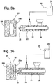
- the reference numeral 25 denotes a shape according to Fig. 3a has two mold halves 25a and 25b and is in the open state.
- the mold 25 is closed and the plastic is passed through a mold opening in a mold cavity 26th injected.
- the pressure in the plastic melt decreases, wherein the dissolved gas expands and the gas bubbles 17 are formed.
- Fig. 3c After curing of the plastic part is in accordance with Fig. 3c the mold is opened and the molding 11 is removed from the mold. According to Fig. 3c the molding 11 is still provided with a sprue projection 27, which is subsequently removed.
- FIG. 4 An alternative foaming process for plastic components according to SULZER is in Fig. 4 shown.
- the only difference to the method according to Mucell is that the gas is not introduced into the screw space 21 of the plasticizing cylinder 20, but into a nozzle 28 of the plasticizing cylinder 20.
- the gas 23 during the injection into the mold is introduced into the melt, where it dissolves in the melt.
- foaming can also be carried out chemically in a manner not shown.
- the plastic granules before plasticizing a blowing agent is added, which releases a gas with increasing warming, which is distributed in the plastic melt.
- the generation of the display layer 12 may, for. B. by printing the finished molded part 11.
- the display layer 12 can be produced by applying a lacquer layer, eg using the in-mold decoration (IMD) method.
- IMD in-mold decoration
- the basic structure of a corresponding device is in Fig. 5 shown.
- a carrier web 29 can be unwound from a first roll 30 and wound on a second roll 31 become.
- On the carrier web 29 are adhered areas of varnish layers 32, which respectively form the symbols 13.
- the carrier web 29 is passed between the two mold halves of the mold 25. Before an injection molding process, the carrier web 29 is positioned so that a lacquer layer 32a is aligned with the mold cavity of a mold half of the mold 25. After closing the mold 25 and injecting the plastic material, the paint layer is released by the increased pressure and temperature in the mold. During the injection process of the carrier and connects to the produced plastic component, such that the lacquer layer 32a abuts an outer surface 33 of the molding 11. After opening the mold 25, the molded part 11 of the mold 25 is removed and the carrier web 29 is further promoted, in which it is wound on the second roller 31. Another paint layer 32b is aligned with the mold cavity 26.
- FIG Fig. 6 An alternative method for applying a display layer 12 is shown in FIG Fig. 6 shown.
- the paint layer 32 is not arranged on a carrier web, but each arranged on a separate, not shown, carrier, for. B. on a slide.
- the carrier is manually inserted into a mold half of the mold 25. Thereafter, the mold is closed and the paint layer is back-injected. Due to the increased pressure and the elevated temperature in the mold during the injection process, the lacquer layer separates from the carrier and adheres to the molded part 11. Otherwise, this method does not differ from the IMD method.
- the sensor layer 14 may be e.g. then be glued to the display layer 12.
Landscapes
- Engineering & Computer Science (AREA)
- Mechanical Engineering (AREA)
- Manufacturing & Machinery (AREA)
- Human Computer Interaction (AREA)
- Aviation & Aerospace Engineering (AREA)
- Transportation (AREA)
- Injection Moulding Of Plastics Or The Like (AREA)
Abstract
Description
- Die Erfindung betrifft zunächst eine Anzeigevorrichtung. Eine solche Anzeigevorrichtung ist aus offenkundiger Vorbenutzung bekannt. Hier ist die Anzeigevorrichtung z.B. Bestandteil eines Bedienteils für bestimmte Fahrzeugfunktionen, wie z.B. Heizung, Lüftung, Sitzverstellung. Die Anzeigevorrichtung umfasst ein Formteil aus transparentem Kunststoff mit einem Anzeigebereich (Display), auf welchem die unterschiedlichen Steuerungsfunktionen in Form von Symbolen angezeigt werden und durch Berühren auch bedient werden können. Dafür ist die Anzeigevorrichtung mit einem Touch-Display versehen.
- Der Anzeigebereich der Anzeigevorrichtung ist mit einer Lichtquelle beleuchtet. Im Stand der Technik ist das Formteil mit einer die Symbole aufweisenden Lackschicht versehen.
- Ein unerwünschter Effekt bestand darin, dass die Lichtquelle dem Benutzer als Lichtpunkt oder Spot erschien. In Versuchen wurde ein Kunststoffmaterial mit einem Füllstoff verwendet, durch welchen das Formteil mit dem Anzeigefeld eine transluzente oder durchscheinende Eigenschaft erhielt. Dieses Kunststoffmaterial verursachte jedoch etwa die fünffachen Kosten des transparenten Kunststoffmaterials.
- Es war Aufgabe der Erfindung eine Anzeigevorrichtung mit einem Formteil zu schaffen, welches einen transluzenten Anzeigebereich aufweist und kostengünstig herstellbar ist.
- Die Aufgabe wird gelöst durch eine Anzeigevorrichtung mit den Merkmalen des Anspruchs 1.
- Die Anzeigevorrichtung umfasst eine Lichtquelle sowie ein Formteil. Formteil ist im Sinne der Erfindung ein Bauteil aus Kunststoff. Es kann z. B. einen Anzeigebereich aufweisen. Anzeigebereich ist im Sinne der Anmeldung z.B. ein ebener, gewölbter oder frei geformter Bereich des Formteils, auf welchem Symbole darstellbar sind. Symbole können z.B. Zahlen, Buchstaben oder Figuren sein. Die Blende kann mittels wenigstens einer Lichtquelle beleuchtet werden. Als Lichtquelle kommen alle denkbaren Leuchtmittel in Betracht, wie z.B. Glühbirne, LED, Halogenlampen, Leuchtstoffröhren etc.
- Das Formteil oder zumindest ein ggf, vorhandener Anzeigebereich, weist eine Vielzahl von Gasblasen auf. Die Gasblasen sind In den Kunststoff integriert. Z.B. sind in dem gesamten Volumen des Formteils Gasblasen angeordnet. Z.B. sind die Gasblasen über das gesamte Volumen des Formteils diffus verteilt angeordnet. Die Gasblasen sind insbesondere in dem Kunststoff derart verteilt, dass das Formteil eine transluzente Wirkung hat. Transluzent bedeutet im Sinne der Anmeldung, dass das Formteil nur durchscheinend, nicht aber klar durchsichtig, also transparent ist. Das fertige Formteil ist ein geschäumtes Kunststoffbauteil und bildet eine Blende.
- Der Kunststoff ist z.B. von einem transparenten Kunststoff gebildet. D.h. der Kunststoff ist z.B. klar durchsichtig. Die transluzente Eigenschaft erhält der Kunststoff durch die in dem Kunststoff verteilten Gasblasen.
- Das Formteil ist von einem geschäumten Kunststoffbauteil gebildet. Dabei ist eine Vielzahl von Gasblasen von festem Kunststoff eingeschlossen. Grundsätzlich kann der Schaum z. B. chemisch oder physikalisch erzeugt werden, d.h. die Gasblasen können chemisch oder physikalisch in den Kunststoff eingebracht werden.
- Bei dem chemischen Schäumen wird dem Kunststoff ein Treibmittel zugesetzt. Das Treibmittel kann z.B. dem Kunststoffgranulat beigemengt werden, welches als Ausgangsmaterial der Erzeugung des Formteils dient. Während der Plastifizierung des Kunststoffs zersetzt sich das chemische Treibmittel, wobei es Gas abgibt. Bei dem Gas kann es sich z.B. um CO2 handeln. Das Gas geht in der Schmelze in Lösung.
- Zum physikalischen Schäumen wird während der Plastifizierung des Kunststoffs ein Fluid (Stickstoff oder Kohlendioxid) in die Schmelze geleitet. Das Gas wird z.B. direkt in den Plastifizierzylinder (Verfahren nach Mucell) oder gemäß einem alternativen Verfahren z.B. während des Einspritzvorgangs des Kunststoffs in die Düse des Plastifizierzylinders (Verfahren nach SULZER) eingeleitet. Das Gas löst sich in der Schmelze. Es expandiert, sobald die Schmelze in die Form gespritzt wird.
- Das Formteil, insbesondere ein Anzeigebereich des Formteils, weist z.B. eine Anzeigeschicht auf, welche mit wenigstens einem Symbol versehen ist. Symbole, wie z.B. Zahlen, Buchstaben, Figuren etc., können z.B. auf dem als Blende ausgebildeten Formteil vorgesehen sein. Die Symbole können z.B. unmittelbar auf das Formteil gedruckt oder auf das Formteil aufgebracht sein oder auf ein Zusatzteil, wie Folie oder Kunststoffteil, aufgebracht sein, welches auf das Formteil aufgeklebt, mit dem Formteil durch Stoffschluss verbunden, oder an dem Formteil mechanisch befestigt wird.
- Nachfolgend sind zwei Verfahren beschrieben, mit denen eine Lackschicht als Anzeigeschicht stoffschlüssig mit dem Formteil verbunden werden kann, indem sie hinterspritzt wird.
- Bei dem In-Mold-Labeling-Verfahren (IML) wird ein mit den Darstellungen versehener Träger, z. B. eine Folie, in eine Formhälfte der Form eingelegt. Der Träger weist eine Lackschicht auf, welche die Darstelllungen ausbildet. Der Kunststoff wird dann in die Form eingespritzt. Unter dem erhöhten Druck und der erhöhten Temperatur während des Spritzgießvorgangs löst sich die Lackschicht von dem Träger und haftet an dem Formteil an, Anschließend wird die Form geöffnet und das Formteil wird der Form entnommen. Das fertige, als Blende ausgebildete Formteil ist dann mit der Lackschicht, welche die Darstellungen enthält, stoffschlüssig verbunden.
- Bei dem In-Mold-Decoration-Verfahren (IMD) ist eine Trägerbahn mit einer Vielzahl von Lackschicht-Bereichen versehen, welche jeweils die Darstellungen enthalten. Die Trägerbahn wird von einer ersten Rolle abgewickelt und auf eine zweite Rolle aufgewickelt. Zwischen der ersten Rolle und der zweiten Rolle durchlauft die Trägerbahn die Spritzgießform. Einer der auf der Trägerbahn angeordneten Lackschicht-Bereiche wird so zu einer Formhälfte positioniert, dass sich beim Schließen der Form die Lackschicht unter erhöhtem Druck und erhöhter Temperatur von der Trägerbahn löst und an dem Spritzgießteil anhaftet. Während des Spritzgießvorgangs verbleibt die Trägerbahn in der Form und die Lackschichtwird von der Trägerbahn abgelöst und verbindet sich mit dem Spritzgießteil. In diesem Fall ist das fertige Formteil mit der Lackschicht versehen, welche die Darstellung enthält. Nach dem Öffnen der Form wird die Trägerbahn derart weitergefördert, dass der nächste auf der Trägerbahn angeordnete Lackschicht-Bereich in der Formhälfte positioniert wird.
- Der Anzeigebereich ist z.B. mit einer Sensorvorrichtung versehen. Die Sensorvorrichtung umfasst z.B. eine Sensorschicht. Diese bildet z. B. mit dem hinterleuchteten Anzeigebereich und der Anzeigeschicht ein Touch-Display. Die Sensorschicht umfasst wenigstens einen Bereich, bei dessen Betätigung eine bestimmte Funktion aktiviert bzw. deaktiviert wird. Derartige Funktionen können z.B. die Betätigung eines Fahrzeugsitzes oder von Teilen des Sitzes, die Betätigung der Lüftung, die Betätigung des Fahrzeuglichtes etc. sein.
- Die Blende ist z.B. Teil eines Gehäuses, in welchem die Lichtquelle angeordnet ist. Das Gehäuse kann z.B. weitere Elemente enthalten, die z.B. der Stromversorgung der Lichtquelle dienen.
- Die Erfindung betrifft gemäß einem zweiten Aspekt der Erfindung ein geschäumtes Kunststoffbauteil zur Verwendung als Blende, insbesondere zur Verwendung als Blende in einer Anzeigevorrichtung.
- Aus dem Stand der Technik ist das Schäumen von Kunststoffen bekannt. In Bezug auf den ersten Aspekt der Erfindung wurden das physikalische Schäumen und das chemische Schäumen zur Herstellung eines geschäumten Kunststoffbauteils beschrieben. Im Stand der Technik dient das Schäumen der Kunststoffe der Gewichtsreduktion des erstzeugten Bauteils sowie der Kostenreduktion, weil weniger Material verbraucht wird. Darüber hinaus wird das Schäumen verwendet, um die Schwindung beim Erkalten des Bauteils zu kompensieren und um während des Spritzgießprozesses den Nachdruck in der Form aufrechtzuerhalten.
- Aus offenkundiger Vorbenutzung ist ein Kunststoffgranulat mit Füllstoffen bekannt, welches zum Spritzgießen von Kunststoffbauteilen verwendet wird, wobei die erzeugten Bauteile die Eigenschaft aufweisen, dass sie transluzent sind. Die Kosten des Granulats betragen etwa das fünffache der Kosten für ein transparentes Kunststoff-Material.
- Es war Aufgabe der Erfindung, eine Blende zu schaffen, welche kostengünstig herstellbar ist und transluzent ist.
- Die Aufgabe wird gelöst durch geschäumtes Kunststoffbauteil mit den Merkmalen des Anspruchs 5.
- Das Schäumen des Kunststoffs hat den Effekt, dass das fertig geformte Formteil transluzent ist. D.h., dass ein aus einem Schaum gebildetes Formteil die Eigenschaft aufweist, transluzent aber nicht transparent zu sein und das Licht diffus zu verteilen. Das Formteil bildet damit eine Blende.
- Der Kunststoff, welcher zur Herstellung Schaumteils verwendet wird, ist z.B. ein transparenter Kunststoff. Das fertig geformte, als geschäumtes Kunststoffbauteil ausgebildete Formteil, welches aus einem transparenten Ausgangsmaterial hergestellt ist, weist eine transluzente Eigenschaft auf.
- Gemäß einem dritten Aspekt betrifft die Erfindung ein Verfahren zur Herstellung einer Blende.
- Aus offenkundiger Vorbenutzung ist es bekannt, eine Blende herzustellen, indem ein mit Füllstoffen versehenes Kunststoffmaterial in einer Plastifiziervorrichtung plastifiziert wird. Die Füllstoffe verursachen beim fertigen Formteil die transluzente Eigenschaft. Der plastifizierte Kunststoff wird im Spritzgießverfahren in eine Form eingespritzt. Das fertige Formteil wird ggf. nachbearbeitet und mit einer Lichtquelle hinterleuchtet.
- Das Verfahren war insofern verbesserungswürdig, als das verwendete Kunststoffmaterial viel höhere Kosten verursachte, als ein transparentes Kunststoffmaterial. Bei Verwendung eines transparenten Materials konnte der Betrachter des hinterleuchteten Formteils einen Lichtpunkt, auch Spot genannt, erkennen.
- Es war Aufgabe der Erfindung ein Verfahren zur Herstellung einer transluzenten Blende zu schaffen, welches hinsichtlich der Kosten verbessert ist
- Die Aufgabe wurde gelöst durch ein Verfahren mit den Merkmalen des Anspruchs 7.
- Bei dem Verfahren wird Kunststoff, z.B. in Form eines Granulats, in einen Plastifizierzylinder gefüllt und dort plastifiziert. Das Kunststoffmaterial weist z.B. bereits vor der Plastifizierung einen gasbildenden Stoff auf, der bei der Plastifizierung ein Gas bildet. Gemäß einem alternativen Verfahrensschritt wird ein Gas in den plastifizierten Kunststoff eingebracht und dort gelöst. Das kann z.B. nach dem Mucell-Verfahren oder nach dem Sulzer-Verfahren erfolgen, wie bereits oben in Bezug auf den ersten Erfindungsaspekt erwähnt. Das Gas expandiert beim Eintreten des Kunststoffs in den Formhohlraum. Beim Formen des Kunststoffbauteils wird auf diese Weise ein geschäumtes Kunststoffbauteil erzeugt. Das fertige Formteil bildet ein geschäumtes Kunststoffbauteil. Das Formteil wird z.B. derart zu einer Lichtquelle angeordnet, dass es hinterleuchtet werden kann.
- Das geschäumte Formteil ist transluzent und verteilt das Licht diffus.
- Das Formteil bildet z.B. einen Anzeigebereich, in welchem Symbole dargestellt werden können. Der Anzeigebereich des Formteils wird z.B. mit einer Anzeigeschicht versehen. Um Wiederholungen zu vermeiden wird in Bezug auf die Herstellung dieser Anzeigeschicht auf den ersten Aspekt der Erfindung verwiesen.
- Das Formteil, insbesondere der Anzeigebereich kann z.B. mit einer Sensorschicht einer Sensorvorrichtung versehen werden. Die Sensorschicht ist z.B. parallel zu der Anzeigeschicht angeordnet. Die Sensorschicht umfasst z.B. wenigstens einen Bereich. Bei Berührung des Bereichs wird ein elektrisches Signal an eine Steuerung weitergegeben. Auf diese Weise können bestimmte Funktionen, wie z.B. Fahrzeugfunktionen, gesteuert werden.
- Weitere Vorteile der Erfindung ergeben sich anhand eines in den Figuren dargestellten Ausführungsbeispiels. Die schematischen Figuren zeigen in:
-
Fig. 1 eine Frontansicht einer Anzeigevorrichtung, auf welcher mehrere Symbole dargestellt sind, -
Fig. 2 eine Schnittdarstellung gemäß Schnittlinie II, II inFig. 1 , wobei lediglich ein Ausschnitt der Vorrichtung gezeicht ist, -
Fig.3a bis 3c eine schematische Darstellung des Schäumverfahrens nach Mucell, -
Fig. 4 eine Darstellung des Verfahrens nach SULZER, -
Fig. 5 eine Darstellung des Verfahrensaufbaus bei dem In-Mould-Decoration-Verfahrens (IMD) und -
Fig. 6 eine Darstellung des Fertigungsaufbaus bei dem In-Mould-Labeling-Verfahren (IML). - Eine Anzeigevorrichtung ist in den Figuren insgesamt mit dem Bezugszeichen 10 bezeichnet. Gleiche Bezugszeichen in den unterschiedlichen Figuren bezeichnen entsprechende Teile, auch wenn kleine Buchstaben nachgestellt oder weggelassen sind.
- Die Anzeigevorrichtung 10 umfasst gemäß
Fig. 1 ein Formteil 11, welches Teil eines Gehäuses 36 ist. Das Formteil 11 umfasst einen Anzeigebereich 34, welcher mit einer Anzeigeschicht 12, z. B. in Form einer Lackschicht, versehen ist. Die Anzeigeschicht 12 ist z.B. stoffschlüssig mit dem Formteil 11 verbunden. Alternativ könnte sie z.B. auf dem Formteil 11 aufgeklebt oder auf andere Weise daran befestigt sein oder die Schicht könnte z.B. unmittelbar auf dem Formteil 11 aufgedruckt sein. - Die Anzeigevorrichtung 10 ist im vorliegenden Ausführungsbeispiel ein Bedienteil für einen Fahrzeugsitz. Die Anzeigeschicht 12 umfasst Symbole 13, die auf unterschiedliche Fahrzeugfunktionen, wie Z.B. Lüftung, Heizung oder Fahrzeugsitz, hinweisen. Auf der Anzeigeschicht 12 ist eine Sensorschicht 14 einer Sensorvorrichtung 35 befestigt. Die Sensorschicht 14 kann z.B. in Form einer Sensorfolie ausgebildet sein. Die Symbole 13 erscheinen in Bereichen 15a bis 15e der Sensorfolie. Durch Berühren der Sensorfolie in einem dieser Bereiche wird eine bestimmte Funktion durchgeführt. Die Sensorschicht 14 ist transparent, so dass sie die Darstellung der Symbole 13 nicht beeinträchtig.
- In
Fig. 2 ist eine Schnittansicht der Anzeigevorrichtung 10 dargestellt. Eine Lichtquelle 16 beleuchtet das Formteil 11. Lichtstrahlen 18, passieren das Formteil 11, die Anzeigeschicht 12, sowie die Sensorschicht 14. Auf diese Weise können die Symbole 13 auf einer von der Lichtquelle 16 abgewandten Seite des Formteils 11 von einem Benutzer, der sich z. B. an dem Punkt 19 befindet, betrachtet werden. - Wie in
Fig. 2 zu erkennen ist, weist die Blende 11 Gasblasen 17 auf, die diffus innerhalb der Blende verteilt sind. Lichtstrahlen 18, können den transparenten Kunststoff, der mit dem Bezugszeichen 20 angedeutet ist, passieren, bis sie auf eine Gasblase 17 auftreffen. An der Gasblase 17 wird der Lichtstrahl 18 z.B. gebrochen, an einer weiteren Gasblase 17 wird der abgelenkte Lichtstrahl 18 erneut gebrochen usw. Ein Teil der Lichtstrahlen 18 verlässt das Formteil 11 an der Seite 33 des Formteils 11. Das Formteil 11 ist somit zwar durchscheinend (transluzent), aber nicht klar durchsichtig (transparent). Die durch das Formteil 11 hindurchgehenden Lichtstrahlen 18 werden diffus verteilt, so dass die Anzeigeschicht 12 gleichmäßig ausgeleuchtet wird, Es entsteht kein Ucht-Spot. Das Formteil 11 kann daher z.B, als Blende in einer Anzeigevorrichtung 10 verwendet werden. - Die Anzahl und die Größe der Schaumblasen hängt von der Nukleierung (Anzahl der Kristallisationskeime) und von weiteren physikalischen Parametern, wie Druck-, Temperatur- und Formfüllgrad ab.
- Das Formteil 11 ist z.B. mit integraler Dichtverteilung als Integralschaum erzeugbar. D.h., die Dichte des Formteils 11 nimmt von außen nach innen kontinuierlich ab und weist einen porösen Kern und eine massive Randzone auf.
- Die Herstellung des Formteils 11 kann in einer Spritzgießvorrichtung, wie nachfolgend beschrieben, vorgenommen werden. In den
Fig. 3a bis 3c ist die Herstellung eines geschäumten Spritzgießteils nach Mucell beschrieben. In einen Schneckenraum 21 eines Plastifizierzylinnders 20 der Spritzgießvorrichtung wird ein transparenter Kunststoff 24 in Form eines Kunststoffgranulats eingefüllt und plastifiziert. Aus einem Speicher 22 wird ein Gas 23, z. B. CO2 oder N2, dem Kunststoff 24 zugeführt. Das Gas 23 löst sich in dem Kunststoff 24, der in dem Schneckenraum 21 enthalten ist. - Mit dem Bezugszeichen 25 ist eine Form bezeichnet, die gemäß
Fig. 3a zwei Formhälften 25a und 25b aufweistund sich im geöffneten Zustand befindet. InFig. 3b ist die Form 25 geschlossen und der Kunststoff wird durch eine Formöffnung in einen Formhohlraum 26 eingespritzt. Während des Einspritzens in den Formhohlraum 26 verringert sich der Druck in der Kunststoffschmelze, wobei das gelöste Gas expandiert und die Gasblasen 17 entstehen. - Nach dem Aushärten des Kunststoffteils wird gemäß
Fig. 3c die Form geöffnet und das Formteil 11 wird aus der Form entnommen. GemäßFig. 3c ist das Formteil 11 noch mit einem Angussvorsprung 27 versehen, welcher anschließend entfernt wird. - Ein alternatives Schäumverfahren für Kunststoffbauteile nach SULZER ist in
Fig. 4 dargestellt. Der einzige Unterschied zu dem Verfahren nach Mucell besteht darin, dass das Gas nicht in den Schneckenraum 21 des Plastifizierzylinders 20 eingeleitet wird, sondern in eine Düse 28 des Plastifizierzylinders 20. Das Gas 23 wir dabei während des Einspritzens in die Form in die Schmelze eingeleitet, wobei es sich in der Schmelze löst. - Alternativ zu den zuvor dargestellten physikalischen Methoden des Schäumens, kann das Schäumen in nicht dargestellter Weise auch chemisch erfolgen. Dabei wird dem Kunststoffgranulat vor der Plastifizierung ein Treibmittel beigemengt, welches mit zunehmender Erwärmung ein Gas freisetzt, dass sich in der Kunststoffschmelze verteilt.
- Die Erzeugung der Anzeigeschicht 12 kann z. B. durch Bedrucken des fertigen Formteils 11 erfolgen.
- Gemäß einer Alternative kann die Anzeigeschicht 12 durch Aufbringen einer Lackschicht, z.B. mit dem In-Mould-Decoration-Verfahren (IMD) erzeugt werden. Der Grundaufbau einer entsprechenden Vorrichtung ist in
Fig. 5 dargestellt. Eine Trägerbahn 29 kann von einer ersten Rolle 30 abgewickelt und auf einer zweiten Rolle 31 aufgewickelt werden. An der Trägerbahn 29 haftenBereiche vonLackschichten 32 an, welche Jeweils die Symbole 13 ausbilden. - Die Trägerbahn 29 ist zwischen den beiden Formhälften der Form 25 hindurchgeführt. Vor einem Spritzgießvorgang wird die Trägerbahn 29 so positioniert, dass eine Lackschicht 32a zu dem Formhohlraum einer Formhälfte der Form 25 ausgerichtet ist. Nach dem Schließen der Form 25 und dem Einspritzen des Kunststoffmaterials löst sich die Lackschicht durch den erhöhten Druck und die erhöhte Temperatur in der Form. während des Spritzvorgangs von dem Träger und verbindet sich mit dem erzeugten Kunststoffbauteil, derart dass die Lackschicht 32a an einer Außenfläche 33 des Formteils 11 anliegt. Nach dem Öffnen der Form 25 wird das Formteil 11 der Form 25 entnommen und die Trägerbahn 29 wird weitergefördert, in dem sie auf der zweiten Rolle 31 aufgewickelt wird. Eine weitere Lackschicht 32b wird zu dem Formhohlraum 26 ausgerichtet.
- Ein alternatives Verfahren zum Aufbringen einer Anzeigeschicht 12 ist in
Fig. 6 dargestellt. Nach dem In-Mold-Labeling-Verfahren (IML) ist die Lackschicht 32 nicht auf einer Trägerbahn angeordnet, sondern jeweils auf einen separaten, nicht dargestellten Träger angeordnet, z. B. auf einer Folie. Der Träger wird manuell in eine Formhälfte der Form 25 eingelegt. Danach wird die Form geschlossen und die Lackschicht wird hinterspritzt. Durch den erhöhten Druck und die erhöhte Temperatur in der Form während des Spritzvorgangs, löst sich die Lackschicht von dem Träger und haftet an dem Formteil 11 an. Ansonsten unterscheidet sich dieses Verfahrens nicht von dem IMD-Verfahren. - Die Sensorschicht 14 kann z.B. anschließend auf die Anzeigeschicht 12 aufgeklebt werden.
Claims (10)
- Anzeigevorrichtung, insbesondere für ein Ausstattungsteil eines Kraftfahrzeugs, mit einer Lichtquelle (16) und mit einem Formteil (11) aus Kunststoff, wobei das Formteil (11) mittels der Lichtquelle (16) beleuchtet werden kann, dadurch gekennzeichnet, dass das Formteil (11) als geschäumtes Kunststoffbauteil ausgebildet ist und eine Blende bildet.
- Anzeigevorrichtung nach Anspruch 1, dadurch gekennzeichnet, dass das Formteil (11) einen Anzeigebereich (34) aufweist, welcher mit einer Anzeigeschicht (12) versehen ist, die wenigstens ein Symbol (13) umfasst.
- Anzeigevorrichtung nach Anspruch 1 oder 2, dadurch gekennzeichnet, dass der Anzeigebereich (34) eine Sensorvorrichtung (35) aufweist und ein Touch-Display bildet.
- Anzeigevorrichtung nach einem der vorhergehenden Ansprüche, dadurch gekennzeichnet, dass das Formteil (11) wenigstens teilweise ein Gehäuse (36) bildet.
- Geschäumtes Kunststoffbauteil aus Kunststoff zur Verwendung als Blende, welche mit einer Lichtquelle (16) hinterleuchtet werden kann, insbesondere zur Verwendung als Blende in einer Anzeigevorrichtung (10) gemäß einem der Ansprüche 1 bis 4.
- Geschäumtes Kunststoffbauteil nach Anspruch 5, dadurch gekennzeichnet, dass der Kunststoff (24) von einem transparenten Kunststoff gebildet ist.
- Verfahren zur Herstellung einer Blende, dadurch gekennzeichnet,
dass Kunststoff (24) in einer Plastifiziervorrichtung plastifiziert wird, dass der Kunststoff (24) einen gasbildenden Stoff aufweist oder dass ein Gas (23) in den plastifizierten Kunststoff (24) eingebracht wird,
dass mit dem plastifizieren Kunststoff (24) im Spritzgießverfahren ein Formteil (11) geformt wird, welches ein geschäumtes Kunststoffbauteil bildet, und
dass das Formteil (11) derart zu einer Lichtquelle (16) angeordnet wird, dass mittels der Lichtquelle (16) ein Anzeigebereich (34) des Formteils (11) beleuchtet werden kann. - Verfahren nach Anspruch 7, dadurch gekennzeichnet, dass das Formteil (11) mit einer Anzeigeschicht (12) mit wenigstens einem Symbol (13) versehen wird, insbesondere indem es bedruckt wird, oder mit einer Lackschicht (32, 32a, 32b) oder mit einem gesonderten Anzeigebauteil versehen wird, welches das Symbol (13) aufweist.
- Verfahren nach einem der Ansprüche 7 oder 8, dadurch gekennzeichnet, dass die Lackschicht (32, 32a, 32b) im IMD oder im IML-Verfahren mit dem Formteil (11) verbunden wird.
- Verfahren nach einem der Ansprüche 7 bis 9, dadurch gekennzeichnet, dass der Anzeigebereich (34) mit einer Sensorschicht (14) einer Sensorvorrichtung (35) versehen wird und ein Touch-Display bildet.
Applications Claiming Priority (1)
| Application Number | Priority Date | Filing Date | Title |
|---|---|---|---|
| DE102015015444.3A DE102015015444A1 (de) | 2015-12-02 | 2015-12-02 | Anzeigevorrichtung, geschäumtes Kunststoffbauteil zur Verwendung als Blende sowie Verfahren zur Herstellung einer Blende |
Publications (2)
| Publication Number | Publication Date |
|---|---|
| EP3175965A1 true EP3175965A1 (de) | 2017-06-07 |
| EP3175965B1 EP3175965B1 (de) | 2023-07-26 |
Family
ID=57389146
Family Applications (1)
| Application Number | Title | Priority Date | Filing Date |
|---|---|---|---|
| EP16002449.3A Active EP3175965B1 (de) | 2015-12-02 | 2016-11-17 | Anzeigevorrichtung sowie verfahren zur herstellung einer blende |
Country Status (3)
| Country | Link |
|---|---|
| EP (1) | EP3175965B1 (de) |
| CN (1) | CN106809063B (de) |
| DE (1) | DE102015015444A1 (de) |
Citations (4)
| Publication number | Priority date | Publication date | Assignee | Title |
|---|---|---|---|---|
| FR2824510A1 (fr) * | 2001-05-14 | 2002-11-15 | Peugeot Citroen Automobiles Sa | Planche de bord pour vehicule automobile |
| DE102005013879A1 (de) * | 2005-03-24 | 2006-09-28 | Siemens Ag | Verfahren zur Herstellung eines Kunststoffformteils |
| FR2937928A1 (fr) * | 2008-10-30 | 2010-05-07 | Faurecia Interieur Ind | Panneau de garnissage de vehicule automobile comprenant une zone formant pictogramme et une peau d'epaisseur variable |
| DE102012101315A1 (de) * | 2012-02-17 | 2013-08-22 | Novem Car Interior Design Gmbh | Formteil und Verfahren zur Herstellung eines Formteils |
Family Cites Families (7)
| Publication number | Priority date | Publication date | Assignee | Title |
|---|---|---|---|---|
| DE19705536A1 (de) * | 1997-02-13 | 1998-08-20 | Mannesmann Vdo Ag | Zifferblatt |
| US7242393B2 (en) * | 2001-11-20 | 2007-07-10 | Touchsensor Technologies Llc | Touch sensor with integrated decoration |
| DE20210601U1 (de) * | 2002-07-02 | 2003-11-20 | Unicontrol Systemtechnik GmbH, 09669 Frankenberg | Einrichtung zur Anzeige von Informationen und technischen Daten, insbesondere in einem Fahrzeug |
| DE102007034110B4 (de) * | 2006-08-04 | 2014-05-22 | Preh Gmbh | Bedienknopf für ein Bedienelement eines Kraftfahrzeuges |
| KR100964466B1 (ko) * | 2009-11-24 | 2010-06-16 | 엘지전자 주식회사 | 디스플레이 장치 |
| EP2520453A1 (de) * | 2011-05-03 | 2012-11-07 | Peguform Gmbh | Vorrichtung zur Darstellung visueller Informationen in einem Kraftfahrzeug |
| DE202011102184U1 (de) * | 2011-06-17 | 2011-11-10 | Vpw Nink Gmbh | Transparente lichtstreuende Kunststoffprofilplatte |
-
2015
- 2015-12-02 DE DE102015015444.3A patent/DE102015015444A1/de not_active Ceased
-
2016
- 2016-11-17 EP EP16002449.3A patent/EP3175965B1/de active Active
- 2016-12-02 CN CN201611099757.6A patent/CN106809063B/zh active Active
Patent Citations (4)
| Publication number | Priority date | Publication date | Assignee | Title |
|---|---|---|---|---|
| FR2824510A1 (fr) * | 2001-05-14 | 2002-11-15 | Peugeot Citroen Automobiles Sa | Planche de bord pour vehicule automobile |
| DE102005013879A1 (de) * | 2005-03-24 | 2006-09-28 | Siemens Ag | Verfahren zur Herstellung eines Kunststoffformteils |
| FR2937928A1 (fr) * | 2008-10-30 | 2010-05-07 | Faurecia Interieur Ind | Panneau de garnissage de vehicule automobile comprenant une zone formant pictogramme et une peau d'epaisseur variable |
| DE102012101315A1 (de) * | 2012-02-17 | 2013-08-22 | Novem Car Interior Design Gmbh | Formteil und Verfahren zur Herstellung eines Formteils |
Also Published As
| Publication number | Publication date |
|---|---|
| EP3175965B1 (de) | 2023-07-26 |
| DE102015015444A1 (de) | 2017-06-08 |
| CN106809063A (zh) | 2017-06-09 |
| CN106809063B (zh) | 2020-08-04 |
Similar Documents
| Publication | Publication Date | Title |
|---|---|---|
| EP3313720B1 (de) | Verfahren zur herstellung eines kunststoffrahmens für ein zweirad | |
| DE68929311T2 (de) | Verfahren zum einspritzgiessformen | |
| DE69202709T2 (de) | Verfahren zur Herstellung eines geformten Hohlkörpers. | |
| DE102011109369A1 (de) | Verfahren und Vorrichtung zur Herstellung eines dreidimensionalen Gegenstandes mit Faserzuführung | |
| EP0546130B1 (de) | Verfahren zum herstellen von mehrschichtigen formkörpern | |
| WO2008017697A1 (de) | Verkleben und beschichten von rohstofflagen | |
| DE2104590A1 (de) | Verfahren zur herstellung von geschaeumten kernformlingen | |
| DE10306780B4 (de) | Verfahren und Vorrichtung für Schaumspritzguss | |
| DE19822113C1 (de) | Verfahren zum Herstellen von Formteilen und Vorrichtung zu seiner Durchführung | |
| DE102004060810A1 (de) | Kunststoff-Formteil und Verfahren zu dessen Herstellung | |
| EP2018260A1 (de) | Verfahren zur herstellung eines mehrschichtteiles | |
| DE102009010195A1 (de) | Schäumformstruktur, Verfahren zum Formen eines geschäumten Produktes, und geschäumtes Produkt | |
| DE102014011135A1 (de) | Verfahren und Vorrichtung zur Herstellung eines Dekorteils | |
| DE102018207296B4 (de) | Verfahren zum herstellen eines dekorteils | |
| EP3243633A1 (de) | 3d-druck von werkstücken mit zellstruktur, insbesondere aus kunststoff | |
| WO2009030366A2 (de) | Verfahren und vorrichtung zur herstellung von faserverstärkten kunststoffformteilen | |
| DE102017214388A1 (de) | Verfahren zur Herstellung eines Funktions-Interieurbauteils für ein Fahrzeug | |
| EP3175965B1 (de) | Anzeigevorrichtung sowie verfahren zur herstellung einer blende | |
| DE102013018578B4 (de) | Verfahren zur Herstellung eines polyurethanüberfluteten Kunststoffbauteils | |
| DE102014112890A1 (de) | Vorrichtung und Verfahren zur Herstellung einer Verzierung für ein Fahrzeug | |
| DE102017208098A1 (de) | Spritzgussvorrichtung und Verfahren zum Herstellen eines Innenverkleidungsbauteils | |
| EP0897787B1 (de) | Verfahren und Vorrichtung zur Herstellung einer mehrfarbigen Verbundfolie aus thermoplastischem Kunststoff | |
| DE1948454A1 (de) | Verfahren und Vorrichtung zum Spritzgiessen von Kunststoffverbundteilen | |
| DE2059628B1 (de) | Verfahren und Vorrichtung zur Herstellung eines einstueckigen Spritzgusskoerpers aus thermoplastischem Kunststoff mit Oberflaechenbeschichtung | |
| DE10110908A1 (de) | Verfahren zur Herstellung eines mehrschichtigen Verbundteils und Werkzeug |
Legal Events
| Date | Code | Title | Description |
|---|---|---|---|
| AK | Designated contracting states |
Kind code of ref document: A1 Designated state(s): AL AT BE BG CH CY CZ DE DK EE ES FI FR GB GR HR HU IE IS IT LI LT LU LV MC MK MT NL NO PL PT RO RS SE SI SK SM TR |
|
| AX | Request for extension of the european patent |
Extension state: BA ME |
|
| PUAI | Public reference made under article 153(3) epc to a published international application that has entered the european phase |
Free format text: ORIGINAL CODE: 0009012 |
|
| STAA | Information on the status of an ep patent application or granted ep patent |
Free format text: STATUS: THE APPLICATION HAS BEEN PUBLISHED |
|
| STAA | Information on the status of an ep patent application or granted ep patent |
Free format text: STATUS: REQUEST FOR EXAMINATION WAS MADE |
|
| 17P | Request for examination filed |
Effective date: 20171207 |
|
| RBV | Designated contracting states (corrected) |
Designated state(s): AL AT BE BG CH CY CZ DE DK EE ES FI FR GB GR HR HU IE IS IT LI LT LU LV MC MK MT NL NO PL PT RO RS SE SI SK SM TR |
|
| STAA | Information on the status of an ep patent application or granted ep patent |
Free format text: STATUS: EXAMINATION IS IN PROGRESS |
|
| 17Q | First examination report despatched |
Effective date: 20181130 |
|
| RAP1 | Party data changed (applicant data changed or rights of an application transferred) |
Owner name: GRAMMER AG |
|
| GRAP | Despatch of communication of intention to grant a patent |
Free format text: ORIGINAL CODE: EPIDOSNIGR1 |
|
| STAA | Information on the status of an ep patent application or granted ep patent |
Free format text: STATUS: GRANT OF PATENT IS INTENDED |
|
| INTG | Intention to grant announced |
Effective date: 20230317 |
|
| GRAS | Grant fee paid |
Free format text: ORIGINAL CODE: EPIDOSNIGR3 |
|
| GRAA | (expected) grant |
Free format text: ORIGINAL CODE: 0009210 |
|
| STAA | Information on the status of an ep patent application or granted ep patent |
Free format text: STATUS: THE PATENT HAS BEEN GRANTED |
|
| AK | Designated contracting states |
Kind code of ref document: B1 Designated state(s): AL AT BE BG CH CY CZ DE DK EE ES FI FR GB GR HR HU IE IS IT LI LT LU LV MC MK MT NL NO PL PT RO RS SE SI SK SM TR |
|
| REG | Reference to a national code |
Ref country code: GB Ref legal event code: FG4D Free format text: NOT ENGLISH |
|
| REG | Reference to a national code |
Ref country code: CH Ref legal event code: EP |
|
| REG | Reference to a national code |
Ref country code: DE Ref legal event code: R096 Ref document number: 502016015958 Country of ref document: DE |
|
| REG | Reference to a national code |
Ref country code: IE Ref legal event code: FG4D Free format text: LANGUAGE OF EP DOCUMENT: GERMAN |
|
| REG | Reference to a national code |
Ref country code: LT Ref legal event code: MG9D |
|
| REG | Reference to a national code |
Ref country code: NL Ref legal event code: MP Effective date: 20230726 |
|
| PG25 | Lapsed in a contracting state [announced via postgrant information from national office to epo] |
Ref country code: NL Free format text: LAPSE BECAUSE OF FAILURE TO SUBMIT A TRANSLATION OF THE DESCRIPTION OR TO PAY THE FEE WITHIN THE PRESCRIBED TIME-LIMIT Effective date: 20230726 |
|
| PG25 | Lapsed in a contracting state [announced via postgrant information from national office to epo] |
Ref country code: GR Free format text: LAPSE BECAUSE OF FAILURE TO SUBMIT A TRANSLATION OF THE DESCRIPTION OR TO PAY THE FEE WITHIN THE PRESCRIBED TIME-LIMIT Effective date: 20231027 |
|
| PG25 | Lapsed in a contracting state [announced via postgrant information from national office to epo] |
Ref country code: IS Free format text: LAPSE BECAUSE OF FAILURE TO SUBMIT A TRANSLATION OF THE DESCRIPTION OR TO PAY THE FEE WITHIN THE PRESCRIBED TIME-LIMIT Effective date: 20231126 |
|
| PG25 | Lapsed in a contracting state [announced via postgrant information from national office to epo] |
Ref country code: SE Free format text: LAPSE BECAUSE OF FAILURE TO SUBMIT A TRANSLATION OF THE DESCRIPTION OR TO PAY THE FEE WITHIN THE PRESCRIBED TIME-LIMIT Effective date: 20230726 Ref country code: RS Free format text: LAPSE BECAUSE OF FAILURE TO SUBMIT A TRANSLATION OF THE DESCRIPTION OR TO PAY THE FEE WITHIN THE PRESCRIBED TIME-LIMIT Effective date: 20230726 Ref country code: PT Free format text: LAPSE BECAUSE OF FAILURE TO SUBMIT A TRANSLATION OF THE DESCRIPTION OR TO PAY THE FEE WITHIN THE PRESCRIBED TIME-LIMIT Effective date: 20231127 Ref country code: NO Free format text: LAPSE BECAUSE OF FAILURE TO SUBMIT A TRANSLATION OF THE DESCRIPTION OR TO PAY THE FEE WITHIN THE PRESCRIBED TIME-LIMIT Effective date: 20231026 Ref country code: LV Free format text: LAPSE BECAUSE OF FAILURE TO SUBMIT A TRANSLATION OF THE DESCRIPTION OR TO PAY THE FEE WITHIN THE PRESCRIBED TIME-LIMIT Effective date: 20230726 Ref country code: LT Free format text: LAPSE BECAUSE OF FAILURE TO SUBMIT A TRANSLATION OF THE DESCRIPTION OR TO PAY THE FEE WITHIN THE PRESCRIBED TIME-LIMIT Effective date: 20230726 Ref country code: IS Free format text: LAPSE BECAUSE OF FAILURE TO SUBMIT A TRANSLATION OF THE DESCRIPTION OR TO PAY THE FEE WITHIN THE PRESCRIBED TIME-LIMIT Effective date: 20231126 Ref country code: HR Free format text: LAPSE BECAUSE OF FAILURE TO SUBMIT A TRANSLATION OF THE DESCRIPTION OR TO PAY THE FEE WITHIN THE PRESCRIBED TIME-LIMIT Effective date: 20230726 Ref country code: GR Free format text: LAPSE BECAUSE OF FAILURE TO SUBMIT A TRANSLATION OF THE DESCRIPTION OR TO PAY THE FEE WITHIN THE PRESCRIBED TIME-LIMIT Effective date: 20231027 Ref country code: FI Free format text: LAPSE BECAUSE OF FAILURE TO SUBMIT A TRANSLATION OF THE DESCRIPTION OR TO PAY THE FEE WITHIN THE PRESCRIBED TIME-LIMIT Effective date: 20230726 |
|
| PG25 | Lapsed in a contracting state [announced via postgrant information from national office to epo] |
Ref country code: PL Free format text: LAPSE BECAUSE OF FAILURE TO SUBMIT A TRANSLATION OF THE DESCRIPTION OR TO PAY THE FEE WITHIN THE PRESCRIBED TIME-LIMIT Effective date: 20230726 |
|
| PG25 | Lapsed in a contracting state [announced via postgrant information from national office to epo] |
Ref country code: ES Free format text: LAPSE BECAUSE OF FAILURE TO SUBMIT A TRANSLATION OF THE DESCRIPTION OR TO PAY THE FEE WITHIN THE PRESCRIBED TIME-LIMIT Effective date: 20230726 |
|
| REG | Reference to a national code |
Ref country code: DE Ref legal event code: R097 Ref document number: 502016015958 Country of ref document: DE |
|
| PG25 | Lapsed in a contracting state [announced via postgrant information from national office to epo] |
Ref country code: SM Free format text: LAPSE BECAUSE OF FAILURE TO SUBMIT A TRANSLATION OF THE DESCRIPTION OR TO PAY THE FEE WITHIN THE PRESCRIBED TIME-LIMIT Effective date: 20230726 Ref country code: RO Free format text: LAPSE BECAUSE OF FAILURE TO SUBMIT A TRANSLATION OF THE DESCRIPTION OR TO PAY THE FEE WITHIN THE PRESCRIBED TIME-LIMIT Effective date: 20230726 Ref country code: ES Free format text: LAPSE BECAUSE OF FAILURE TO SUBMIT A TRANSLATION OF THE DESCRIPTION OR TO PAY THE FEE WITHIN THE PRESCRIBED TIME-LIMIT Effective date: 20230726 Ref country code: EE Free format text: LAPSE BECAUSE OF FAILURE TO SUBMIT A TRANSLATION OF THE DESCRIPTION OR TO PAY THE FEE WITHIN THE PRESCRIBED TIME-LIMIT Effective date: 20230726 Ref country code: DK Free format text: LAPSE BECAUSE OF FAILURE TO SUBMIT A TRANSLATION OF THE DESCRIPTION OR TO PAY THE FEE WITHIN THE PRESCRIBED TIME-LIMIT Effective date: 20230726 Ref country code: CZ Free format text: LAPSE BECAUSE OF FAILURE TO SUBMIT A TRANSLATION OF THE DESCRIPTION OR TO PAY THE FEE WITHIN THE PRESCRIBED TIME-LIMIT Effective date: 20230726 Ref country code: SK Free format text: LAPSE BECAUSE OF FAILURE TO SUBMIT A TRANSLATION OF THE DESCRIPTION OR TO PAY THE FEE WITHIN THE PRESCRIBED TIME-LIMIT Effective date: 20230726 |
|
| PG25 | Lapsed in a contracting state [announced via postgrant information from national office to epo] |
Ref country code: IT Free format text: LAPSE BECAUSE OF FAILURE TO SUBMIT A TRANSLATION OF THE DESCRIPTION OR TO PAY THE FEE WITHIN THE PRESCRIBED TIME-LIMIT Effective date: 20230726 |
|
| PLBE | No opposition filed within time limit |
Free format text: ORIGINAL CODE: 0009261 |
|
| STAA | Information on the status of an ep patent application or granted ep patent |
Free format text: STATUS: NO OPPOSITION FILED WITHIN TIME LIMIT |
|
| REG | Reference to a national code |
Ref country code: CH Ref legal event code: PL |
|
| PG25 | Lapsed in a contracting state [announced via postgrant information from national office to epo] |
Ref country code: MC Free format text: LAPSE BECAUSE OF FAILURE TO SUBMIT A TRANSLATION OF THE DESCRIPTION OR TO PAY THE FEE WITHIN THE PRESCRIBED TIME-LIMIT Effective date: 20230726 |
|
| 26N | No opposition filed |
Effective date: 20240429 |
|
| PG25 | Lapsed in a contracting state [announced via postgrant information from national office to epo] |
Ref country code: LU Free format text: LAPSE BECAUSE OF NON-PAYMENT OF DUE FEES Effective date: 20231117 |
|
| PG25 | Lapsed in a contracting state [announced via postgrant information from national office to epo] |
Ref country code: CH Free format text: LAPSE BECAUSE OF NON-PAYMENT OF DUE FEES Effective date: 20231130 |
|
| PG25 | Lapsed in a contracting state [announced via postgrant information from national office to epo] |
Ref country code: MC Free format text: LAPSE BECAUSE OF FAILURE TO SUBMIT A TRANSLATION OF THE DESCRIPTION OR TO PAY THE FEE WITHIN THE PRESCRIBED TIME-LIMIT Effective date: 20230726 Ref country code: LU Free format text: LAPSE BECAUSE OF NON-PAYMENT OF DUE FEES Effective date: 20231117 Ref country code: CH Free format text: LAPSE BECAUSE OF NON-PAYMENT OF DUE FEES Effective date: 20231130 Ref country code: SI Free format text: LAPSE BECAUSE OF FAILURE TO SUBMIT A TRANSLATION OF THE DESCRIPTION OR TO PAY THE FEE WITHIN THE PRESCRIBED TIME-LIMIT Effective date: 20230726 |
|
| REG | Reference to a national code |
Ref country code: BE Ref legal event code: MM Effective date: 20231130 |
|
| REG | Reference to a national code |
Ref country code: IE Ref legal event code: MM4A |
|
| PG25 | Lapsed in a contracting state [announced via postgrant information from national office to epo] |
Ref country code: IE Free format text: LAPSE BECAUSE OF NON-PAYMENT OF DUE FEES Effective date: 20231117 |
|
| PG25 | Lapsed in a contracting state [announced via postgrant information from national office to epo] |
Ref country code: BE Free format text: LAPSE BECAUSE OF NON-PAYMENT OF DUE FEES Effective date: 20231130 |
|
| PG25 | Lapsed in a contracting state [announced via postgrant information from national office to epo] |
Ref country code: IE Free format text: LAPSE BECAUSE OF NON-PAYMENT OF DUE FEES Effective date: 20231117 Ref country code: BE Free format text: LAPSE BECAUSE OF NON-PAYMENT OF DUE FEES Effective date: 20231130 |
|
| PG25 | Lapsed in a contracting state [announced via postgrant information from national office to epo] |
Ref country code: BG Free format text: LAPSE BECAUSE OF FAILURE TO SUBMIT A TRANSLATION OF THE DESCRIPTION OR TO PAY THE FEE WITHIN THE PRESCRIBED TIME-LIMIT Effective date: 20230726 |
|
| PG25 | Lapsed in a contracting state [announced via postgrant information from national office to epo] |
Ref country code: BG Free format text: LAPSE BECAUSE OF FAILURE TO SUBMIT A TRANSLATION OF THE DESCRIPTION OR TO PAY THE FEE WITHIN THE PRESCRIBED TIME-LIMIT Effective date: 20230726 |
|
| REG | Reference to a national code |
Ref country code: AT Ref legal event code: MM01 Ref document number: 1591469 Country of ref document: AT Kind code of ref document: T Effective date: 20231117 |
|
| PG25 | Lapsed in a contracting state [announced via postgrant information from national office to epo] |
Ref country code: AT Free format text: LAPSE BECAUSE OF NON-PAYMENT OF DUE FEES Effective date: 20231117 |
|
| PG25 | Lapsed in a contracting state [announced via postgrant information from national office to epo] |
Ref country code: AT Free format text: LAPSE BECAUSE OF NON-PAYMENT OF DUE FEES Effective date: 20231117 |
|
| PG25 | Lapsed in a contracting state [announced via postgrant information from national office to epo] |
Ref country code: CY Free format text: LAPSE BECAUSE OF FAILURE TO SUBMIT A TRANSLATION OF THE DESCRIPTION OR TO PAY THE FEE WITHIN THE PRESCRIBED TIME-LIMIT; INVALID AB INITIO Effective date: 20161117 |
|
| PG25 | Lapsed in a contracting state [announced via postgrant information from national office to epo] |
Ref country code: HU Free format text: LAPSE BECAUSE OF FAILURE TO SUBMIT A TRANSLATION OF THE DESCRIPTION OR TO PAY THE FEE WITHIN THE PRESCRIBED TIME-LIMIT; INVALID AB INITIO Effective date: 20161117 |
|
| PG25 | Lapsed in a contracting state [announced via postgrant information from national office to epo] |
Ref country code: TR Free format text: LAPSE BECAUSE OF FAILURE TO SUBMIT A TRANSLATION OF THE DESCRIPTION OR TO PAY THE FEE WITHIN THE PRESCRIBED TIME-LIMIT Effective date: 20230726 |
|
| PGFP | Annual fee paid to national office [announced via postgrant information from national office to epo] |
Ref country code: DE Payment date: 20251118 Year of fee payment: 10 |
|
| PGFP | Annual fee paid to national office [announced via postgrant information from national office to epo] |
Ref country code: GB Payment date: 20251120 Year of fee payment: 10 |
|
| PGFP | Annual fee paid to national office [announced via postgrant information from national office to epo] |
Ref country code: FR Payment date: 20251120 Year of fee payment: 10 |