EP3175361B1 - Procédé de reprise sur défaillance proactif pour un calcul distribué - Google Patents
Procédé de reprise sur défaillance proactif pour un calcul distribué Download PDFInfo
- Publication number
- EP3175361B1 EP3175361B1 EP15748354.6A EP15748354A EP3175361B1 EP 3175361 B1 EP3175361 B1 EP 3175361B1 EP 15748354 A EP15748354 A EP 15748354A EP 3175361 B1 EP3175361 B1 EP 3175361B1
- Authority
- EP
- European Patent Office
- Prior art keywords
- node
- computing
- nodes
- checkpoint
- failure
- Prior art date
- Legal status (The legal status is an assumption and is not a legal conclusion. Google has not performed a legal analysis and makes no representation as to the accuracy of the status listed.)
- Active
Links
- 238000011084 recovery Methods 0.000 title claims description 54
- 238000000034 method Methods 0.000 claims description 170
- 230000008569 process Effects 0.000 claims description 102
- 238000013500 data storage Methods 0.000 claims description 14
- 238000013507 mapping Methods 0.000 claims 1
- 230000005055 memory storage Effects 0.000 claims 1
- 238000012545 processing Methods 0.000 description 39
- 230000001419 dependent effect Effects 0.000 description 27
- 230000015654 memory Effects 0.000 description 25
- 238000004891 communication Methods 0.000 description 22
- 238000004590 computer program Methods 0.000 description 12
- 230000004044 response Effects 0.000 description 9
- 230000006870 function Effects 0.000 description 7
- 238000013461 design Methods 0.000 description 6
- 230000003716 rejuvenation Effects 0.000 description 6
- 238000004364 calculation method Methods 0.000 description 5
- 230000036541 health Effects 0.000 description 5
- 230000008901 benefit Effects 0.000 description 3
- 238000004422 calculation algorithm Methods 0.000 description 3
- 238000004088 simulation Methods 0.000 description 3
- 230000000007 visual effect Effects 0.000 description 3
- 230000009471 action Effects 0.000 description 2
- 239000008186 active pharmaceutical agent Substances 0.000 description 2
- 230000007423 decrease Effects 0.000 description 2
- 238000010586 diagram Methods 0.000 description 2
- 230000003993 interaction Effects 0.000 description 2
- 230000005012 migration Effects 0.000 description 2
- 238000013508 migration Methods 0.000 description 2
- 230000003287 optical effect Effects 0.000 description 2
- 230000000737 periodic effect Effects 0.000 description 2
- 238000013515 script Methods 0.000 description 2
- 238000012546 transfer Methods 0.000 description 2
- 208000017387 Ectodermal dysplasia-cutaneous syndactyly syndrome Diseases 0.000 description 1
- 206010048669 Terminal state Diseases 0.000 description 1
- 230000003044 adaptive effect Effects 0.000 description 1
- 238000004458 analytical method Methods 0.000 description 1
- 230000002547 anomalous effect Effects 0.000 description 1
- 238000013459 approach Methods 0.000 description 1
- 230000005540 biological transmission Effects 0.000 description 1
- 230000000903 blocking effect Effects 0.000 description 1
- 230000015556 catabolic process Effects 0.000 description 1
- 239000003795 chemical substances by application Substances 0.000 description 1
- 239000003086 colorant Substances 0.000 description 1
- 239000013256 coordination polymer Substances 0.000 description 1
- 230000003247 decreasing effect Effects 0.000 description 1
- 238000006731 degradation reaction Methods 0.000 description 1
- 238000001514 detection method Methods 0.000 description 1
- 230000000694 effects Effects 0.000 description 1
- 238000002149 energy-dispersive X-ray emission spectroscopy Methods 0.000 description 1
- 230000002708 enhancing effect Effects 0.000 description 1
- 239000003999 initiator Substances 0.000 description 1
- 230000002452 interceptive effect Effects 0.000 description 1
- 239000004973 liquid crystal related substance Substances 0.000 description 1
- 238000007726 management method Methods 0.000 description 1
- 238000004519 manufacturing process Methods 0.000 description 1
- 238000003909 pattern recognition Methods 0.000 description 1
- 230000002265 prevention Effects 0.000 description 1
- 238000013404 process transfer Methods 0.000 description 1
- 230000000644 propagated effect Effects 0.000 description 1
- 230000001902 propagating effect Effects 0.000 description 1
- 230000008439 repair process Effects 0.000 description 1
- 238000011160 research Methods 0.000 description 1
- 239000004065 semiconductor Substances 0.000 description 1
- 230000035945 sensitivity Effects 0.000 description 1
- 230000001953 sensory effect Effects 0.000 description 1
- 239000000758 substrate Substances 0.000 description 1
- 230000004083 survival effect Effects 0.000 description 1
- 230000007704 transition Effects 0.000 description 1
Images


Classifications
-
- G—PHYSICS
- G06—COMPUTING; CALCULATING OR COUNTING
- G06F—ELECTRIC DIGITAL DATA PROCESSING
- G06F11/00—Error detection; Error correction; Monitoring
- G06F11/07—Responding to the occurrence of a fault, e.g. fault tolerance
- G06F11/16—Error detection or correction of the data by redundancy in hardware
- G06F11/20—Error detection or correction of the data by redundancy in hardware using active fault-masking, e.g. by switching out faulty elements or by switching in spare elements
- G06F11/202—Error detection or correction of the data by redundancy in hardware using active fault-masking, e.g. by switching out faulty elements or by switching in spare elements where processing functionality is redundant
- G06F11/2023—Failover techniques
- G06F11/203—Failover techniques using migration
-
- G—PHYSICS
- G06—COMPUTING; CALCULATING OR COUNTING
- G06F—ELECTRIC DIGITAL DATA PROCESSING
- G06F11/00—Error detection; Error correction; Monitoring
- G06F11/07—Responding to the occurrence of a fault, e.g. fault tolerance
- G06F11/0703—Error or fault processing not based on redundancy, i.e. by taking additional measures to deal with the error or fault not making use of redundancy in operation, in hardware, or in data representation
- G06F11/0706—Error or fault processing not based on redundancy, i.e. by taking additional measures to deal with the error or fault not making use of redundancy in operation, in hardware, or in data representation the processing taking place on a specific hardware platform or in a specific software environment
- G06F11/0721—Error or fault processing not based on redundancy, i.e. by taking additional measures to deal with the error or fault not making use of redundancy in operation, in hardware, or in data representation the processing taking place on a specific hardware platform or in a specific software environment within a central processing unit [CPU]
-
- G—PHYSICS
- G06—COMPUTING; CALCULATING OR COUNTING
- G06F—ELECTRIC DIGITAL DATA PROCESSING
- G06F11/00—Error detection; Error correction; Monitoring
- G06F11/07—Responding to the occurrence of a fault, e.g. fault tolerance
- G06F11/0703—Error or fault processing not based on redundancy, i.e. by taking additional measures to deal with the error or fault not making use of redundancy in operation, in hardware, or in data representation
- G06F11/0751—Error or fault detection not based on redundancy
- G06F11/0754—Error or fault detection not based on redundancy by exceeding limits
- G06F11/0757—Error or fault detection not based on redundancy by exceeding limits by exceeding a time limit, i.e. time-out, e.g. watchdogs
-
- G—PHYSICS
- G06—COMPUTING; CALCULATING OR COUNTING
- G06F—ELECTRIC DIGITAL DATA PROCESSING
- G06F11/00—Error detection; Error correction; Monitoring
- G06F11/07—Responding to the occurrence of a fault, e.g. fault tolerance
- G06F11/14—Error detection or correction of the data by redundancy in operation
- G06F11/1402—Saving, restoring, recovering or retrying
- G06F11/1405—Saving, restoring, recovering or retrying at machine instruction level
- G06F11/1407—Checkpointing the instruction stream
-
- G—PHYSICS
- G06—COMPUTING; CALCULATING OR COUNTING
- G06F—ELECTRIC DIGITAL DATA PROCESSING
- G06F11/00—Error detection; Error correction; Monitoring
- G06F11/07—Responding to the occurrence of a fault, e.g. fault tolerance
- G06F11/14—Error detection or correction of the data by redundancy in operation
- G06F11/1402—Saving, restoring, recovering or retrying
- G06F11/1415—Saving, restoring, recovering or retrying at system level
- G06F11/1438—Restarting or rejuvenating
-
- G—PHYSICS
- G06—COMPUTING; CALCULATING OR COUNTING
- G06F—ELECTRIC DIGITAL DATA PROCESSING
- G06F11/00—Error detection; Error correction; Monitoring
- G06F11/07—Responding to the occurrence of a fault, e.g. fault tolerance
- G06F11/14—Error detection or correction of the data by redundancy in operation
- G06F11/1402—Saving, restoring, recovering or retrying
- G06F11/1446—Point-in-time backing up or restoration of persistent data
- G06F11/1458—Management of the backup or restore process
- G06F11/1461—Backup scheduling policy
-
- G—PHYSICS
- G06—COMPUTING; CALCULATING OR COUNTING
- G06F—ELECTRIC DIGITAL DATA PROCESSING
- G06F11/00—Error detection; Error correction; Monitoring
- G06F11/07—Responding to the occurrence of a fault, e.g. fault tolerance
- G06F11/14—Error detection or correction of the data by redundancy in operation
- G06F11/1402—Saving, restoring, recovering or retrying
- G06F11/1471—Saving, restoring, recovering or retrying involving logging of persistent data for recovery
-
- G—PHYSICS
- G06—COMPUTING; CALCULATING OR COUNTING
- G06F—ELECTRIC DIGITAL DATA PROCESSING
- G06F11/00—Error detection; Error correction; Monitoring
- G06F11/30—Monitoring
- G06F11/34—Recording or statistical evaluation of computer activity, e.g. of down time, of input/output operation ; Recording or statistical evaluation of user activity, e.g. usability assessment
Definitions
- US 2002/0087913 describes a method for automatically rejuvenating a component of a distributed data processing environment in which a usage history for a distributed data processing environment is stored.
- the usage history describes multiple levels of overall usage of the distributed data processing environment over time.
- health data relating to at least one component of the distributed data processing environment is received, and, in response, the health data is automatically utilized to determine a failure time within which that component is likely to require rejuvenation.
- the usage history is automatically utilized to identify an optimum rejuvenation time.
- that component is automatically rejuvenated according to the optimum rejuvenation time.
- US 2010/0011254 describes a system that adjusts a checkpointing frequency in a distributed computing system that executes multiple jobs.
- the system receives signals associated with the operation of the computing nodes.
- the system determines risk metrics for the computing nodes using a pattern-recognition technique to identify anomalous signals in the received signals.
- the system adjusts a checkpointing frequency of a given checkpoint for a given computing node based on a comparison of a risk metric associated with the given computing node and a threshold, thereby implementing holistic fault tolerance, in which prediction and prevention of potential faults occurs across the distributed computing system.
- the present disclosure describes methods and systems, including computer-implemented methods, computer-program products, and computer systems, for providing a proactive failure recovery model for distributed computing according to an implementation.
- the invention is defined in the independent claims 1, 8, 9.
- the described failure recovery model system and method has an inexpensive framework design that permits reliable, continued operation of computational processes even if a partial/severe computational node (e.g., a computer server, etc.) failure occurs - enhancing business continuity optimality.
- the failure recovery model system allows continued operation and achieves a high performance rating for optimally executing failed job executions. Because the failure recovery model is proactive (rather than reactive) costs are further reduced for re-processing jobs and allows for cost avoidance and both time and effort saving from failure recovery practices.
- the framework is scalable for a huge number of computational nodes.
- the framework design takes into account different disaster recovery principles factors.
- the described system and method will greatly minimize overhead caused by unnecessary process checkpointing.
- Fifth, the described system and method can be configured to practice any type of load-balancing technique to optimize processing.
- Sixth, the system and method does not rely on localized or centralized checkpoint storage for operation.
- Seventh, the system and method relies on a failure predication model to control an optimum placement of a checkpoint process.
- Eighth, the proposed system and method design permits a high degree of business continuity optimality. Other advantages will be apparent to those of ordinary skill in the art.
- Ninth, the failure predication model within this framework design can capture and address any type of failures (power supply, software, hardware, network, etc.).
- This patent generally describes methods and systems, including computer-implemented methods, computer-program products, and computer systems, for providing a proactive failure recovery model (FRM) for distributed computing to ensure business continuity optimality in the case computing node (e.g., a computer server, etc.) failure.
- FAM proactive failure recovery model
- Checkpointing is an effective technique widely applicable in high-performance computing environments and the most effective fault tolerant technique used in case of a failure during the execution of a process in distributed systems.
- the state of a process executing on a node is saved periodically on reliable and stable storage, such as a hard disk, flash memory, etc.
- checkpointing creates a file describing a running process (e.g., the above-described "state of a process") with which an operating system can use to later reconstruct the process.
- the checkpoint file can contain data about a stack, heap, and register(s) of the checkpointed process.
- the checkpoint file can also contain the status of pending signals, signal handlers, accounting records, terminal state, and any other necessary data needed to reconstruct a process at a given point-in-time. A process is therefore enabled to continue execution at and from the point where a particular checkpoint was taken rather from the beginning by freshly restarting the process anew.
- the FRM is configured to maintain consistent subject application/process throughput, maintain a minimally necessary set of checkpoints to optimize/minimize process rework execution time, achieve an optimal load-balancing strategy among recovery survival nodes (described in more detail below), minimize diskless or input/output operations, store checkpoint data in a stable and secure storage, and/or minimize memory overhead.
- the FRM can also reduce checkpointing latency (a time between when a process initiates a checkpoint request and a global checkpoint process completes it) through the use of non-blocking checkpointing that will not block processing jobs that are in an execution mode unless a processing job is hosted in a node participating in a recovery. As a result, processing job execution latency is reduced.
- the described FRM is, in some instances, implemented as: 1) a scalable, virtual, tree-like structure supporting a high-performance, stable computing system in cases of failure-free computing and high availability of recovery resources in cases of failure-occurrence; and 2) a failure prediction model (FPM) used in typical instances to minimize an overhead of coordination and context switching of checkpoint-based algorithms by measuring effectiveness of and a need for each checkpoint request.
- FPM failure prediction model
- a hierarchal tree-like computing topology design allows multiple options for allocation of both recovery-nodes and remote designated checkpoint data storage nodes that could reside in a different physical location).
- all computing nodes (nodes) participating in a distributed computing effort are virtually placed into a virtual tree-like structure as determined by two different parameters: 1) computing power (CP - placed on a Y-axis) and 2) node location (NLOC - placed on X-axis) to build the virtual tree-like structure.
- other parameters can be collected and/or used on either the Y- or X-axis to allow for tangible/meaningful classification and to build the described virtual tree-like structure.
- MTBF mean time between failure
- Failure in distributed computing environment can, in some implementations, be classified into five different categories which must be accounted for to ensure a robust and comprehensive failure recovery model.
- categories can include: 1) crash failure - a server halts, but is working correctly until it halts; 2) omission failure (either receive or send omission) - a server fails to respond to incoming requests, a server fails to receive incoming messages, a server fails to send messages; 3) timing failure - a server's response lies outside the specified time interval; 4) response failure (value or state transition failure) - a server's response is incorrect; the value of the response is wrong, the server deviates from the correct flow of control; 5) an arbitrary failure - s server may produce arbitrary responses at arbitrary times.
- a distributed computing node structure e.g., nodes N0; N1; N2;...; Nn
- a network connection locally or globally (e.g., Internet or other network cloud).
- Each node typically has its own physical memory and local disk (e.g., a stand-alone computing device) and a stable shared storage is deployed for large dataset sharing between nodes.
- communication between nodes' processes can be accomplished through a message passing interface (MPI), shared memory designated for global send/receive requests between processes, and/or other communication method.
- MPI message passing interface
- shared memory designated for global send/receive requests between processes, and/or other communication method.
- each process resides on a different node, but two or more separate processes can execute on a single node.
- a node failure situation for a particular node will typically be determined (e.g., predicted by the node's software agent - each node typically has its own service daemon "agent") / notified cooperatively (to designated participating nodes in the record table saved in each node that describes the structure of the computing environment) by any node residing at a same level as the particular node in the virtual tree-like structure.
- the predication of the particular node's failure is an important indicator allowing assessment of the risk of failure for some time in the near future and to take proactive steps to save a finer progression (higher granularity) of process states associated with the particular node.
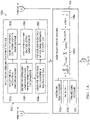
- FIGs. 1A-1C 1illustrate a collective method 100 (divided into sub-methods 100a, 100b, and 100c) for providing a proactive failure recovery model for distributed computing according to an implementation.
- providing a proactive failure recovery model for distributed computing can include more or less steps/operations, including more of each described step/operation.
- Method 100 (or any of its individual sub-methods) may be performed by any suitable system, environment, software, and/or hardware, or a combination of systems, environments, software, and/or hardware as appropriate (e.g., the computer system described in FIG. 10 below).
- various steps of method 100 can be run in parallel, in combination, in loops, or in any order.
- a virtual tree-like structured model of nodes is built using available nodes in a distributed computing system.
- the tree-like structure is considered "virtual" as the tree of nodes is not actually arranged in the tree-like structure, but is mapped in this manner to communicate in a parent/child-type relationship.
- CP computing power
- NLOC node location
- CP is considered on the Y-axis and NLOC (or other parameter(s)) is(are) can be considered on the X-axis of the virtual tree-like structured model of nodes.
- At 103a at least computing power (CP), node location (NLOC), and/or other parameters are collected for all nodes of a distributed computing system participating in processing of, for example, a computational process.
- this collected data is placed into a data structure, file, etc. (e.g., a node-record-information table) for use by a virtual tree creation process (not illustrated).
- each node is aware of all other nodes and associated parameters. For example, each node can have access to the data structure/file containing collected parameter information for the nodes in the distributed computing system. This information can be used to allow each node to be aware of its siblings, descendants, etc. From 103a, method 100a proceeds to 103b.
- nodes are divided into collections based upon their location (NLOC). From 103b, method 100a proceeds to 103c.
- the nodes are sorted within each collection based on the node CP parameter. From 103c, method 100a proceeds to 103d.
- the lower limit and upper limit (i.e., thresholds) for each level is determined from a cross-plot of the collected parameters from the nodes.
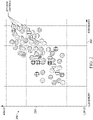
- FIG. 2 illustrates an example cross-plot of collected parameters from nodes that can be used to build a node virtual tree-like structure according to an implementation.
- each node (note that hashing/patterns can represent colors to indicate different locations (NLOCs) - e.g., all "blue” plotted nodes are at a particular location while all "green” plotted nodes are at a different particular location) can be plotted according to, in some implementations, a memory parameter value (e.g., low-to-high - say a range of 8GB-64GB of computer server memory) on the X-axis 202 and CP parameter value (low-to-high - say a range of 1.6-3.5GHz processor clock) on the Y-axis 204.
- a memory parameter value e.g., low-to-high - say a range of 8GB-64GB of computer server memory
- CP parameter value low-to-high - say a range of 1.6-3.5GHz processor clock
- horizontal placement of a node is CP-based depending on the node's location within the cross-plot of FIG. 2 .
- a node's CP parameter and location a node could be in a bottom, middle, or top position in the virtual tree-like structure.
- the horizontal placement could, in some instances be generally that a most-bottom attached node would be a node with a highest CP parameter value (higher computational ability), while the higher in the tree-like structure a node is placed, the lower the CP parameter value is (lower computational ability).
- the vertical placement of a node depends upon different classifiable criteria, for example physical location, subnet, bandwidth speed, power supply line, etc. and balances the virtual tree-like structure by default. For example, if the x-axis criteria used in the cross-plot guides placement of a particular node in the tree structure, the virtual tree-like structure is balanced and can be used as an indicator as to whether a correct physical disaster-recovery setup is applied in a computational environment. Additional criteria used to separate nodes vertically can include, among other things physical location, subnet, bandwidth speed, power supply line, and/or other additional criteria. From 103d, method 100a proceeds to 103e.
- a horizontal and/or vertical tree placement entry for each node is made in a node-record-information table. From 103e, method 100a proceeds to 103f.
- the node-record-information table for each node is populated with an associated designated checkpoint and/or recovery node(s) for the node.
- ancestor and descendent nodes can be determined for each node in the virtual tree-like structure and the node-record-information table updated with this information.
- another node e.g., one or more direct children
- the checkpoint nodes are not a sibling, child, or ancestor node of the particular node in the virtual tree-like structure.
- the designated recovery node and checkpoint node for a particular node can be the same. From 103f, method 100a proceeds to 104 (a node failure prediction model).
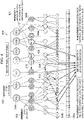
- FIG. 3 illustrates an example virtual tree-like structure 300 of nodes according to an implementation (e.g., as built according to 103a-103f above).
- 302a, 302b, ..., 302n illustrate collections of nodes by location (NLOC), for example places in different network subnets.
- 304a, 304b, ..., 304n are nodes sorted by the CP parameter and divided into horizontal levels by a cross-plot of collected parameters from the nodes. For example, node 304a could have a higher CP parameter value than node 304n.
- nodes e.g., 306a and 306b
- nodes are separated vertically within the same horizontal level based upon the above-described (or other) different classifiable criteria - for example physical location, subnet, bandwidth speed, etc.
- An example unique node identification (node ID) value is shown inside some nodes (e.g., 304n displays "N1(1)" for level 1, node 1 and node 306b displays "N2(13)" for level 2, node 13), and so on (although node IDs below N2 are not illustrated). Any suitable unique node identifier is envisioned to be within the scope of this disclosure.
- the topology of the virtual tree-like structure is adaptive. For example, if more or less nodes are added to a particular location, a node CP value changes, nodes are swapped for higher-CP/memory models, etc., the relationship tree within that NLOC-divided collection can be updated and relationships with other nodes in other NLOC-divided collections can also be updated. For example, if a new node is added to the distributed computing system, the virtual tree-like structure creation process can execute again. In some instances, the tree can be partially or wholly restructured.
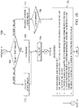
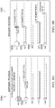
- FIG. 4A illustrates node performance values 400a used in a calculation of a MTBF according to an implementation.
- 402 is a failure start point (the time at which a failure begins (or “down time")) and 404 is a recovery start point 404 (the time at which processing restarts (or "up time”)).
- 406 is the time between failures (the difference between the "down time” and the "up time” is the amount of time operating between the two events).
- 408 represents a failure.
- FIG. 4B illustrates the typical academic formula 400b used for calculating a MTBF for a node according to an implementation.
- the MTBF is a sum of operational periods (e.g., for a node) divided by a number of observed failures 408 (e.g., again for the node).
- a number of observed failures 408 e.g., again for the node.
- other variations of MTBF or similar values using more or less data values and consistent with this disclosure could also be used in a prediction of node failure and resultant actions as describe below. From 104, method 100a proceeds to method 100b ( FIG. 1B ).
- decisions 100b whether to checkpoint a process state and/or to migrate a process are performed.
- the checkpoint time calculation is to minimize system overhead of taking a checkpoint of a node to times in which it is deemed more necessary (e.g., based on the MTBF for the node).
- the MTBF for a node calculated in method 100a is compared to a minimum threshold (MinLimit) and a maximum threshold (MaxLimit).
- MinLimit and MaxLimit are set to some predetermined time value.
- the MinLimit value can be changed as needed (e.g., to determine when to perform a next health check on a node).
- the MaxLimit can also be changed as necessary (e.g., to reflect an increasing MTBF value).
- method 100b proceeds to 108.
- no checkpoint of the node is taken. From 108, method 100b proceeds to 110.
- the time for taking the next checkpoint is adjusted based on a new MTBF calculation performed for the node by the software agent for the node (assesses the current state of the node in terms of failures - how many failures happened in the last time period).
- the checkpoint interval can dynamically adjust depending upon the state of the node. For example, after the first checkpoint, if five minutes is set for the next checkpoint, five minutes is waited. After the next checkpoint, a MTBF assessment is performed based on failures (if any) within the last five minutes. Based on the MTBF calculated, the checkpoint interval can be adjusted up or down (e.g., as in FIG. 5 ). From 110, method 100b proceeds to 104 described in relation to FIG. 1A .
- method 100b proceeds to 112.
- no checkpoint of the node is taken and MaxLimit is updated to equal the MTBF.
- a MaxLimit above a particular threshold can initiate the generation of an alert that the MaxLimit is too high. From 112, method 100b proceeds to 110.
- method 100b proceeds to 114.
- a checkpoint of the node is taken and MinLimit is updated to equal the currently calculated MTBF value.
- the checkpoint can include, among other things, the process state (register contents), memory contents, communication state (e.g., opened files and message channels), relevant kernel context, and/or queued jobs. From 114, method 100b proceeds to 116.
- a decision is performed as to whether jobs (processes) should be migrated is based on a threshold for proactive failure recovery (e.g., MTBF ⁇ MinLimit value as determined at 106).
- the threshold value can be enforced subjectively depending upon failure frequencies in a particular node. If it is determined that jobs should not be migrated, method 100b proceeds to 110. If, it is determined that jobs should be migrated, method 100b proceeds to 118 to perform a job migration.
- FIG. 5 is a graph illustrating checkpoint interval placement in relation to MTBF according to an implementation.
- the time between checkpoints (checkpoint intervals) (e.g., 502a, 502b, and 502c) becomes shorter as the MTBF decreases (e.g., 504a, 504b, and 504c which correspond to the example checkpoint intervals, respectively).
- the checkpoint intervals decrease (e.g., at 502d).
- FIG. 1C illustrates a method flow 100c for migrating jobs between nodes.
- recovery node software agents negotiate to determine which node should host a job to migrate. In some implementations, the negotiation is for load balancing purposes. In other implementations, other parameters/criteria can be used for negotiation purposes. From 119a, method 100c proceeds to 109b.
- the process state of the node is extracted.
- the process state can include, among other things, the process state (register contents), memory contents, communication state (e.g., opened files and message channels), relevant kernel context, and/or queued jobs. From 119c, method 100c proceeds to 119e.
- the last checkpoint is used in place of the current node state (because the node has failed and is "down"/unavailable to retrieve a process state from).
- the checkpoint can include, among other things, the process state (register contents), memory contents, communication state (e.g., opened files and message channels), relevant kernel context, and/or queued jobs. From 119d, method 100c proceeds to 119e.
- the failed ancestor recovery node software agent will keep forwarding signals/communications to a new recovery node (e.g., by searching messages at a communication protocol level). Note that in some implementations, if a failed node is repaired, responsibility to forward signals/communication can be performed by the repaired node (at which point the repaired node will be handed over the process of forwarding signals/communication). From 119e, method 100c proceeds to 119f.
- a process transfer is performed from the "down" node to the recovery node.
- the transferred state typically includes a process's address space, execution point (register contents), communication state (e.g., open files and message channels), and/or other operating system dependent state. From 119f, method 100c proceeds to 119g.
- the process is resumed to execute on the recovery node. From 119g, method 100c stops. Returning to FIG. 1B , from 118, method 118 for the particular down node stops.
- the failed node is isolated from the current computational run if a job migration has been performed for it and the failed node cannot be returned to the same job family and participate even if repaired (e.g., the node is removed from the node-record-information table for one or more nodes in the virtual tree-like structure and must wait until the start of a new computational run). Processing returns to FIG. 1A for a different node using the node failure prediction model.
- the repaired node can be re-integrated into the virtual tree-like structure node-record-information tables, processed by the node failure prediction model, and begin processing, forwarding signals/communication, etc.).
- a node failure prediction model is executed to, among other things, evaluate a current machine state for each node in order to determine whether to perform a checkpoint of the node, migrate a job (process) from one node to another node, etc.
- the calculation of a MTBF for each node is calculated by a software agent residing/executing on at least one node residing in the same level in the tree structure as a particular node to be evaluated for a failure condition and/or on the particular node itself. For example, in FIG. 3 , any node in the level in which node 304b resides can determine and MTBF for node 304b and notify appropriate nodes of this determination.
- values that can be used in the failure prediction model include one or more system logs 105a (e.g., network connection failures/refusals, packet loss, computational speed degradation, low memory conditions, storage/network issues, etc.), generated, for example, by a "health check"-type/"heartbeat” program, an adjustment to the time period to check 105b (e.g., a dynamically calculated value that represent a period of time to wait to perform a next health check performed by a function executing on each node participating in computations.
- system logs 105a e.g., network connection failures/refusals, packet loss, computational speed degradation, low memory conditions, storage/network issues, etc.
- an adjustment to the time period to check 105b e.g., a dynamically calculated value that represent a period of time to wait to perform a next health check performed by a function executing on each node participating in computations.
- the function is invoked after dynamically calculating a time period to check 105b value to determine the next time period) and a failure class dictionary 105c gathered periodically (e.g., a tp period of time).
- a time period to check 105b value to determine the next time period e.g., a tp period of time.
- the types of issues, failures, etc. can be weighted (e.g., network/storage are more important, etc.).
- a failure type frequency is calculated by classifying every failure with a weight value subjectively assigned to each class of failure to measure impact when calculating a failure frequency at every tp period of time. For example, electrical power supply and network connectivity can be monitored and their failure type frequencies can be calculated for a particular period of time tp. In other implementations, the failure type frequency can be calculated using any appropriate algorithm. At 105e, in some implementations, the MTBF can be calculated by dividing 1 by the calculated failure type frequency.
- FIG. 6 illustrates an example virtual tree-like structure 600 of nodes when a partial node failure occurs and how the recovery model is used for a recovery according to an implementation. Achieving a recovery in the virtual tree-like structure is accomplished, first, by a notification from any node at a same level of a failed node's descendants to be recovered otherwise a notification will be sent to the failed node's ancestors.
- node 602 if node 602 fails, node 602's direct children (descendants) 604 or further descendants 606, which have a higher computing power then that parent node, will detect that an issue has occurred (e.g., loss of connection with node 602, data receipt from node 602 stops, heartbeat detection for node 502 indicates node failure, etc.).
- the question is which other node(s) should replace node 602 to handle the jobs being performed by node 602 to optimize the business continuity.
- the options are either parent node 604 or descendant nodes 606 or 608.
- nodes 606 or 608 can be assigned the jobs for node 602 (due to their much higher computing power CP) in order to complete the jobs originally run on node 602 in a faster period of time to optimize business continuity.
- the decision to use the descendants of node 602 can also be dependent upon the loading of the child nodes as determined by a load balancing analysis of the descendant nodes.
- the recovery for any failed node by allocating any alive, available and lightly loaded (determined by load-balancing in the system) nodes from the node's siblings-decedents (if no one of the failed node's direct descendants is alive) is referred to as generation-stop. For example, if node 610 fails, node 610's children should detect the failure of node 610. In this example, however, all the children of node 610 are also down. The question then becomes which node(s) should replace node 510 to complete node 510's jobs.
- the ancestor node 612 is notified (e.g., by a communication protocol between two jobs residing on two different nodes - such as message passing interface (MPI) and/or other protocol) of the failure of node 610 and will seek a relative at its same level to take over processing of at least failed node 610's jobs (and in some instances the jobs of node 610's descendants as well).
- node 612 communicates with node 614 (note that node 614 can be in a different subnet - refer to FIG. 3 ) to see if it and its children can assume the processing of failed node 610's jobs.
- node 614 can delegate the jobs to its direct children which can delegate the jobs to their children, etc. as appropriate (e.g., based on computing power, subject, load-balancing, etc.) to optimize business continuity.
- one or both direct child nodes of node 614 can also communicate with a child node of a different parent node (e.g., node 616) to also enlist its assistance in working on jobs originally linked to failed node 610 or node 614 and its sibling to its right 618 (or other nodes at the level of 612).
- the recovery should be performed starting from the most bottom-up nodes (with higher CP values) where the most descendent nodes of other siblings' descendant nodes will participate in the recovery of the leaf nodes only then the leaf nodes will participate to recovery of their ancestor tree.
- FIG. 7 illustrates checkpointing data storage nodes for the nodes of the virtual tree like structure when a node is experiencing a semi-failure according to an implementation.
- node 610 has a designated one or more checkpointing data storage nodes 702 for storing checkpoint data.
- node 704 also has one or more checkpointing data storage nodes 702 designated as a checkpointing data storage node for node 610.
- multiple nodes can share the same checkpointing data storage node(s).
- a checkpointing data storage node 702 is only used by one node or a few nodes (e.g., in the same subnet, siblings, etc.) to expand the number of checkpointing data storage nodes so that a failure of one or more checkpointing data storage nodes does not cause the loss of much checkpointing data. If a node fails, the node that is tasked with recovery for that node can access the node-record-information table to determine the default designated recovery node and checkpointing data storage node for the failed node.
- each process maintains only one permanent checkpoint. This reduces overall storage overhead and eliminates the need for garbage collection activities to clean up unused/abandoned checkpoints.
- checkpoint data for each node is saved in nodes that are in the same level (e.g., in siblings) of a node because the probability of failure of those nodes at the same time is low.
- checkpoint data storage nodes are implemented in this manner to minimize risks of capturing safe states for a local job.
- the checkpoint data storage nodes have information for the currently related jobs either in the execution mode including work set data residing in memory for those jobs or queued in a queue.
- FIG. 8 illustrates nodes participating in application computations according to an implementation.
- a checkpoint request will be initiated by a node's software agent where a degree of the predication model or desired reliability requires a checkpoint. If a node has an independent process (e.g., thread, etc.), X, it just performs check pointing action with its own corresponding checkpoint storage nodes in the tree without propagating the request to other nodes (as there are no other nodes participating in independent process X).
- independent process e.g., thread, etc.
- a process is a dependent process (e.g., dependent on other processes)
- a minimal checkpoint approach will be applied where the checkpoint initiator node identifies all the processes with which it has communicated since last checkpoint/normal communication and propagates a request to all of them.
- each process Upon receiving the request, each process in turn identifies all the processes it has communicated with and propagates a request to them and so on until no more processes can be identified.
- both dependent process nodes 802 and independent process nodes 804 are identified.
- node 806 is the top-level node for a particular process.
- the nodes executing processes dependent on node 806's process are indicated by corresponding arrows.
- a failure is communicated (e.g., by parent node 810) to all participating process nodes (e.g., 812, etc.) because they are working together and it is necessary for the other nodes to save the state of their processes until the other dependent process node (e.g., 806) is recovered and then the dependent processes can continue where they left off.
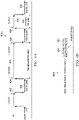
- FIGs. 9A and 9B illustrate a checkpointing node request with respect to independent and dependent processes 900a and 900b, respectively, according to an implementation.
- FIG. 9A illustrates independent processes. For example, if independent process N3 902 receives a checkpoint request, the checkpoint of N3 is performed without regard to other processes. In the case of a dependent process N2 902b as in FIG. 9B , once a checkpoint request is received, the process N2 902b passes a checkpoint request to processes directly dependent upon it, for example, dependent process N3 904b.
- Dependent process 904B then passes a checkpoint request to processes directly dependent upon it (e.g., dependent processes N41 906b and N46 908b), and so on.
- a checkpoint may occur slightly later for lower level dependent processes (e.g., dependent processes N41 906b and N46 908b) than the checkpoint for the "parent" dependent processes above (e.g., dependent process N3 904b) due to time for informing/requesting checkpoints from dependent processes.
- each dependent process can notify the requesting dependent process of when its checkpointing operation is complete.
- FIG. 10 is a block diagram illustrating an example computing device 1000 used for providing a proactive failure recovery model for distributed computing according to an implementation.
- the EDCS 1000 includes a computer 1002 and a network 1030.
- multiple computers and/or networks can work together to perform the above-described method(s).
- the illustrated computer 1002 is intended to encompass a computing device such as a computer server, but can also include a desktop computer, laptop/notebook computer, wireless data port, smart phone, personal data assistant (PDA), tablet computing device, one or more processors within these devices, or any other suitable processing device, including both physical and/or virtual instances of the computing device.
- the computer 1002 may comprise a computer that includes an input device, such as a keypad, keyboard, touch screen, or other device (not illustrated) that can accept user information, and an output device (not illustrated) that conveys information associated with the operation of the computer 1002, including digital data, visual and/or audio information, or a user interface.
- the computer 1002 can serve as a client and/or a server.
- the computer 1002 acts as either a parallel processing node and also hosts, among other things, a software agent or other application, process, method, etc. consistent with this disclosure (even if not illustrated) (e.g., application 1007).
- the illustrated computer 1002 is communicably coupled with a network 1030.
- one or more components of the computer 1002 may be configured to operate within a parallel-processing and/or cloud-computing-based environment. Implementations of the computer 1002 can also communicate using message passing interface (MPI) or other interface over network 1030.
- MPI message passing interface
- the computer 1002 is an electronic computing device operable to receive, transmit, process, store, or manage data and information associated with providing a proactive failure recovery model for distributed computing according to an implementation.
- the computer 1002 may also include or be communicably coupled with a simulation server, application server, e-mail server, web server, caching server, streaming data server, analytics server, and/or any other server.
- the computer 1002 can receive requests over network 1030 from an application 1007 (e.g., executing on another computer 1002) and respond to the received requests by processing the said requests in an appropriate software application 1007.
- requests may also be sent to the computer 1002 from internal users (e.g., from a command console or by other appropriate access method), external or third-parties, other automated applications, as well as any other appropriate entities, individuals, systems, or computers.
- Each of the components of the computer 1002 can communicate using a system bus 1003.
- any and/or all the components of the computer 1002, both hardware and/or software may interface with each other and/or the interface 1004 over the system bus 1003 using an application programming interface (API) 1012 and/or a service layer 1013.
- the API 1012 may include specifications for routines, data structures, and object classes.
- the API 1012 may be either computer-language independent or dependent and refer to a complete interface, a single function, or even a set of APIs.
- the service layer 1013 provides software services to the computer 1002 and/or system of which the computer 1002 is a part. The functionality of the computer 1002 may be accessible for all service consumers using this service layer.
- Software services such as those provided by the service layer 1013, provide reusable, defined business functionalities through a defined interface.
- the interface may be software written in JAVA, C++, or other suitable language providing data in extensible markup language (XML) format or other suitable format.
- XML extensible markup language
- alternative implementations may illustrate the API 1012 and/or the service layer 1013 as stand-alone components in relation to other components of the computer 1002.
- any or all parts of the API 1012 and/or the service layer 1013 may be implemented as child or sub-modules of another software module, enterprise application, or hardware module without departing from the scope of this disclosure.
- the computer 1002 includes an interface 1004. Although illustrated as a single interface 1004 in FIG. 10 , two or more interfaces 1004 may be used according to particular needs, desires, or particular implementations of the computer 1002.
- the interface 1004 is used by the computer 1002 for communicating with other systems in a distributed environment - including a parallel processing environment- connected to the network 1030 (whether illustrated or not).
- the interface 1004 comprises logic encoded in software and/or hardware in a suitable combination and operable to communicate with the network 1030. More specifically, the interface 1004 may comprise software supporting one or more communication protocols associated with communications over network 1030.
- the computer 1002 includes a processor 1005. Although illustrated as a single processor 1005 in FIG. 10 , two or more processors may be used according to particular needs, desires, or particular implementations of the computer 1002. Generally, the processor 1005 executes instructions and manipulates data to perform the operations of the computer 1002. Specifically, the processor 1005 executes the functionality required for providing a proactive failure recovery model for distributed computing.
- the computer 1002 also includes a memory 1006 that holds data for the computer 1002 and/or other components of a system of which the computer is a part. Although illustrated as a single memory 1006 in FIG. 10 , two or more memories may be used according to particular needs, desires, or particular implementations of the computer 1002. While memory 1006 is illustrated as an integral component of the computer 1002, in alternative implementations, memory 1006 can be external to the computer 1002. In some implementations, memory 1006 can hold and/or reference one or more of, any data described with respect to method 100 (e.g., checkpoint data coverage scores, sameness scores, depth ratios, etc.) and/or any other appropriate data consistent with this disclosure.
- any data described with respect to method 100 e.g., checkpoint data coverage scores, sameness scores, depth ratios, etc.
- the application 1007 is an algorithmic software engine providing functionality according to particular needs, desires, or particular implementations of the computer 1002 and/or a system of which the computer 1002 is a part, particularly with respect to functionality required to, for some implementations, for providing a proactive failure recovery model for distributed computing.
- application 1007 can serve as (or a portion of) a software host, scientific processing application, checkpointing application, recovery application, and/or any other type of application consistent with this disclosure (whether illustrated or not).
- the application 1007 may be implemented as multiple applications 1007 on the computer 1002.
- the application 1007 can be external to and execute apart from the computer 1002.
- computers 1002 there may be any number of computers 1002 associated with a distributed computer system performing functions consistent with this disclosure. Further, the term “client,” “user,” and other appropriate terminology may be used interchangeably as appropriate without departing from the scope of this disclosure. Moreover, this disclosure contemplates that many users/processes may use one computer 1002, or that one user/process may use multiple computers 1002.
- Implementations of the subject matter and the functional operations described in this specification can be implemented in digital electronic circuitry, in tangibly-embodied computer software or firmware, in computer hardware, including the structures disclosed in this specification and their structural equivalents, or in combinations of one or more of them.
- Implementations of the subject matter described in this specification can be implemented as one or more computer programs, i.e., one or more modules of computer program instructions encoded on a tangible, non-transitory computer-storage medium for execution by, or to control the operation of, data processing apparatus.
- the program instructions can be encoded on an artificially-generated propagated signal, e.g., a machine-generated electrical, optical, or electromagnetic signal that is generated to encode information for transmission to suitable receiver apparatus for execution by a data processing apparatus.
- the computer-storage medium can be a machine-readable storage device, a machine-readable storage substrate, a random or serial access memory device, or a combination of one or more of them.
- data processing apparatus refers to data processing hardware and encompasses all kinds of apparatus, devices, and machines for processing data, including by way of example, a programmable processor, a computer, or multiple processors or computers.
- the apparatus can also be or further include special purpose logic circuitry, e.g., a central processing unit (CPU), a co-processor (e.g., a graphics/visual processing unit (GPU/VPU)), a FPGA (field programmable gate array), or an ASIC (application-specific integrated circuit).
- the data processing apparatus and/or special purpose logic circuitry may be hardware-based and/or software-based.
- the apparatus can optionally include code that creates an execution environment for computer programs, e.g., code that constitutes processor firmware, a protocol stack, a database management system, an operating system, or a combination of one or more of them.
- code that constitutes processor firmware e.g., code that constitutes processor firmware, a protocol stack, a database management system, an operating system, or a combination of one or more of them.
- the present disclosure contemplates the use of data processing apparatuses with or without conventional operating systems, for example LINUX, UNIX, WINDOWS, MAC OS, ANDROID, IOS or any other suitable conventional operating system.
- a computer program which may also be referred to or described as a program, software, a software application, a module, a software module, a script, or code, can be written in any form of programming language, including compiled or interpreted languages, or declarative or procedural languages, and it can be deployed in any form, including as a stand-alone program or as a module, component, subroutine, or other unit suitable for use in a computing environment.
- a computer program may, but need not, correspond to a file in a file system.
- a program can be stored in a portion of a file that holds other programs or data, e.g., one or more scripts stored in a markup language document, in a single file dedicated to the program in question, or in multiple coordinated files, e.g., files that store one or more modules, sub-programs, or portions of code.
- a computer program can be deployed to be executed on one computer or on multiple computers that are located at one site or distributed across multiple sites and interconnected by a communication network. While portions of the programs illustrated in the various figures are shown as individual modules that implement the various features and functionality through various objects, methods, or other processes, the programs may instead include a number of sub-modules, third-party services, components, libraries, and such, as appropriate. Conversely, the features and functionality of various components can be combined into single components as appropriate.
- the processes and logic flows described in this specification can be performed by one or more programmable computers executing one or more computer programs to perform functions by operating on input data and generating output.
- the processes and logic flows can also be performed by, and apparatus can also be implemented as, special purpose logic circuitry, e.g., a CPU, a FPGA, or an ASIC.
- Computers suitable for the execution of a computer program can be based on general or special purpose microprocessors, both, or any other kind of CPU.
- a CPU will receive instructions and data from a read-only memory (ROM) or a random access memory (RAM) or both.
- the essential elements of a computer are a CPU for performing or executing instructions and one or more memory devices for storing instructions and data.
- a computer will also include, or be operatively coupled to, receive data from or transfer data to, or both, one or more mass storage devices for storing data, e.g., magnetic, magneto-optical disks, or optical disks.
- mass storage devices for storing data, e.g., magnetic, magneto-optical disks, or optical disks.
- a computer need not have such devices.
- a computer can be embedded in another device, e.g., a mobile telephone, a personal digital assistant (PDA), a mobile audio or video player, a game console, a global positioning system (GPS) receiver, or a portable storage device, e.g., a universal serial bus (USB) flash drive, to name just a few.
- PDA personal digital assistant
- GPS global positioning system
- USB universal serial bus
- Computer-readable media suitable for storing computer program instructions and data include all forms of non-volatile memory, media and memory devices, including by way of example semiconductor memory devices, e.g., erasable programmable read-only memory (EPROM), electrically-erasable programmable read-only memory (EEPROM), and flash memory devices; magnetic disks, e.g., internal hard disks or removable disks; magneto-optical disks; and CD-ROM, DVD+/-R, DVD-RAM, and DVD-ROM disks.
- semiconductor memory devices e.g., erasable programmable read-only memory (EPROM), electrically-erasable programmable read-only memory (EEPROM), and flash memory devices
- EPROM erasable programmable read-only memory
- EEPROM electrically-erasable programmable read-only memory
- flash memory devices e.g., electrically-erasable programmable read-only memory (EEPROM), and flash memory devices
- magnetic disks e.g., internal
- the memory may store various objects or data, including caches, classes, frameworks, applications, backup data, jobs, web pages, web page templates, database tables, repositories storing business and/or dynamic information, and any other appropriate information including any parameters, variables, algorithms, instructions, rules, constraints, or references thereto. Additionally, the memory may include any other appropriate data, such as logs, policies, security or access data, reporting files, as well as others.
- the processor and the memory can be supplemented by, or incorporated in, special purpose logic circuitry.
- implementations of the subject matter described in this specification can be implemented on a computer having a display device, e.g., a CRT (cathode ray tube), LCD (liquid crystal display), LED (Light Emitting Diode), or plasma monitor, for displaying information to the user and a keyboard and a pointing device, e.g., a mouse, trackball, or trackpad by which the user can provide input to the computer.
- a display device e.g., a CRT (cathode ray tube), LCD (liquid crystal display), LED (Light Emitting Diode), or plasma monitor
- a keyboard and a pointing device e.g., a mouse, trackball, or trackpad by which the user can provide input to the computer.
- Input may also be provided to the computer using a touchscreen, such as a tablet computer surface with pressure sensitivity, a multi-touch screen using capacitive or electric sensing, or other type of touchscreen.
- a computer can interact with a user by sending documents to and receiving documents from a device that is used by the user; for example, by sending web pages to a web browser on a user's client device in response to requests received from the web browser.
- GUI graphical user interface
- GUI may be used in the singular or the plural to describe one or more graphical user interfaces and each of the displays of a particular graphical user interface. Therefore, a GUI may represent any graphical user interface, including but not limited to, a web browser, a touch screen, or a command line interface (CLI) that processes information and efficiently presents the information results to the user.
- a GUI may include a plurality of UI elements, some or all associated with a web browser, such as interactive fields, pull-down lists, and buttons operable by the business suite user. These and other UI elements may be related to or represent the functions of the web browser.
- Implementations of the subject matter described in this specification can be implemented in a computing system that includes a back-end component, e.g., as a data server, or that includes a middleware component, e.g., an application server, or that includes a front-end component, e.g., a client computer having a graphical user interface or a Web browser through which a user can interact with an implementation of the subject matter described in this specification, or any combination of one or more such back-end, middleware, or front-end components.
- the components of the system can be interconnected by any form or medium of wireline and/or wireless digital data communication, e.g., a communication network.
- Examples of communication networks include a local area network (LAN), a radio access network (RAN), a metropolitan area network (MAN), a wide area network (WAN), Worldwide Interoperability for Microwave Access (WIMAX), a wireless local area network (WLAN) using, for example, 802.11 a/b/g/n and/or 802.20, all or a portion of the Internet, and/or any other communication system or systems at one or more locations.
- the network may communicate with, for example, Internet Protocol (IP) packets, Frame Relay frames, Asynchronous Transfer Mode (ATM) cells, voice, video, data, and/or other suitable information between network addresses.
- IP Internet Protocol
- ATM Asynchronous Transfer Mode
- the computing system can include clients and servers.
- a client and server are generally remote from each other and typically interact through a communication network.
- the relationship of client and server arises by virtue of computer programs running on the respective computers and having a client-server relationship to each other.
- any or all of the components of the computing system may interface with each other and/or the interface using an application programming interface (API) and/or a service layer.
- the API may include specifications for routines, data structures, and object classes.
- the API may be either computer language independent or dependent and refer to a complete interface, a single function, or even a set of APIs.
- the service layer provides software services to the computing system. The functionality of the various components of the computing system may be accessible for all service consumers via this service layer.
- Software services provide reusable, defined business functionalities through a defined interface.
- the interface may be software written in JAVA, C++, or other suitable language providing data in extensible markup language (XML) format or other suitable format.
- the API and/or service layer may be an integral and/or a stand-alone component in relation to other components of the computing system. Moreover, any or all parts of the service layer may be implemented as child or sub-modules of another software module, enterprise application, or hardware module without departing from the scope of this disclosure.
Landscapes
- Engineering & Computer Science (AREA)
- Theoretical Computer Science (AREA)
- General Engineering & Computer Science (AREA)
- Quality & Reliability (AREA)
- Physics & Mathematics (AREA)
- General Physics & Mathematics (AREA)
- Computer Hardware Design (AREA)
- Retry When Errors Occur (AREA)
- Hardware Redundancy (AREA)
- Debugging And Monitoring (AREA)
Claims (9)
- Procédé mis en œuvre par ordinateur fournissant un modèle de reprise sur défaillance en calcul réparti au moyen d'intervalles de points de contrôle ajustables dynamiquement, le procédé comprenant :la construction (102) d'une structure de calcul virtuelle de type arborescence (300, 600, 700, 800) d'une pluralité de nœuds de calcul qui prennent part à un effort de calcul réparti, la structure de calcul virtuelle de type arborescence cartographiant les nœuds pour qu'ils communiquent selon des relations de type parent/enfant ; pour chacun des nœuds de calcul, au moins un enfant direct étant désigné comme nœud de reprise par défaut et un autre nœud étant désigné comme nœud de point de contrôle (702), la construction (102) de la structure de calcul virtuelle de type arborescence comprenanta) la collecte (103a) d'au moins une valeur de paramètre de puissance de calcul et une valeur de paramètre d'emplacement de nœud pour chaque nœud de calcul, la valeur de paramètre de puissance de calcul indiquant une capacité calculatoire d'un nœud de calcul et la valeur de paramètre d'emplacement de nœud indiquant un emplacement du nœud de calcul ;b) la division (103b) des nœuds de calcul en collections (302) sur la base de leur valeur de paramètre d'emplacement de nœud, etc) le classement (103c) des nœuds de calcul au sein de chaque collection sur la base de la valeur de paramètre de puissance de calcul, le classement des nœuds de calcul comprenant le positionnement d'un nœud ayant la plus grande capacité calculatoire dans un nœud connecté le plus en bas dans la structure de type arborescence lorsque celle-ci est représentée au moyen de nœuds-feuilles en bas et des nœuds-racines en haut, plus un nœud est positionné haut dans la structure de type arborescence, plus la capacité calculatoire est faible ;pour chaque nœud de calcul de la structure de calcul virtuelle de type arborescence, la réalisation (104), par un processeur matériel, d'un modèle de prédiction de défaillance de nœud afin de calculer un temps moyen entre défaillances, noté MTBF, (400b) associé au nœud de calcul et mesurer une efficacité et un besoin de requêtes de point de contrôle ;la détermination (106) s'il convient de réaliser un point de contrôle d'un premier nœud de calcul sur la base d'une comparaison entre le MTBF calculé et un seuil maximal et minimal ;si le MTBF calculé est inférieur au seuil minimal, alorsi) la réalisation (114) du point de contrôle afin de sauvegarder, sur l'autre nœud désigné comme nœud de point de contrôle pour le premier nœud de calcul, l'état d'un processus s'exécutant sur le premier nœud de calcul, etii) la détermination (116), sur la base d'un seuil de reprise proactive sur défaillance, qu'il convient de procéder à la migration (118) du processus depuis le premier nœud de calcul vers un nœud de calcul enfant différent jouant le rôle de nœud de reprise ; etla poursuite (119) de l'exécution du processus sur le nœud de calcul enfant différent jouant le rôle de nœuds de reprise, le nœud de reprise étant appelé à continuer à partir du dernier point de contrôle réalisé pour le processus.
- Procédé selon la revendication 1, dans lequel la construction (102) de la structure de calcul virtuelle de type arborescence comprend en outre :l'identification (103d) d'une limite supérieure de la valeur de paramètre de puissance de calcul et d'une limite inférieure de la valeur de paramètre de puissance de calcul afin de déterminer des niveaux des nœuds de calcul qui sont classés sur la base de la valeur de paramètre de puissance de calcul ;le classement (103e) des nœuds de calcul au sein de chaque collection (302) en niveaux horizontaux dans la structure de calcul virtuelle de type arborescence lorsque celle-ci est représentée au moyen de nœuds-feuilles en bas et des nœuds-racines en haut sur la base du paramètre de puissance de calcul et de la limite supérieure et de la limite inférieure ;l'enregistrement (103e) du positionnement en niveau horizontal et d'un positionnement vertical dans la structure de calcul virtuelle de type arborescence dans une table d'informations d'enregistrement de nœud associée à chaque nœud de calcul ; etle peuplement (103f) de chaque table d'informations d'enregistrement de nœud par le nœud de reprise désigné.
- Procédé selon la revendication 2, dans lequel la limite supérieure et la limite inférieure sont déterminées à partir d'un cross-plot des paramètres de puissance de calcul et d'emplacement de nœud collectés pour chaque nœud de calcul, et le positionnement vertical est déterminé sur la base au moins du paramètre d'emplacement de nœud pour chaque nœud de calcul.
- Procédé selon la revendication 1, dans lequel le MTBF est calculé sur la base au moins d'une défaillance de réseau ou de stockage de données.
- Procédé selon la revendication 1, comprenant en outre :la création d'un point de contrôle lorsque le MTBF du premier nœud de calcul est inférieur au seuil minimal ; etla mise à jour du seuil minimal associé au nœud de calcul pour le rendre égal au MTBF.
- Procédé selon la revendication 5, comprenant en outre :la détermination qu'une défaillance du premier nœud de calcul s'est produite ; etl'utilisation du dernier point de contrôle pris pour le premier nœud de calcul comme état du processus.
- Procédé selon la revendication 1, dans lequel, pour chacun des nœuds de calcul dans la structure de calcul virtuelle de type arborescence, l'autre nœud désigné comme nœud de point de contrôle n'est pas un nœud frère, enfant ou ancêtre de ce nœud de calcul particulier.
- Support non transitoire lisible par ordinateur stockant des instructions lisibles par ordinateur, les instructions étant exécutables par un ordinateur et configurées pour réaliser le procédé selon l'une quelconque des revendications 1 à 7.
- Système ordinateur, comprenant :
au moins un processeur matériel couplé de manière mutuellement fonctionnelle à une unité de stockage en mémoire et configuré pour réaliser le procédé selon l'une quelconque des revendications 1 à 7.
Applications Claiming Priority (2)
| Application Number | Priority Date | Filing Date | Title |
|---|---|---|---|
| US14/445,369 US9348710B2 (en) | 2014-07-29 | 2014-07-29 | Proactive failure recovery model for distributed computing using a checkpoint frequency determined by a MTBF threshold |
| PCT/US2015/041121 WO2016018663A1 (fr) | 2014-07-29 | 2015-07-20 | Procédé de reprise sur défaillance proactif pour un calcul distribué |
Publications (2)
| Publication Number | Publication Date |
|---|---|
| EP3175361A1 EP3175361A1 (fr) | 2017-06-07 |
| EP3175361B1 true EP3175361B1 (fr) | 2022-07-20 |
Family
ID=53801170
Family Applications (1)
| Application Number | Title | Priority Date | Filing Date |
|---|---|---|---|
| EP15748354.6A Active EP3175361B1 (fr) | 2014-07-29 | 2015-07-20 | Procédé de reprise sur défaillance proactif pour un calcul distribué |
Country Status (6)
| Country | Link |
|---|---|
| US (1) | US9348710B2 (fr) |
| EP (1) | EP3175361B1 (fr) |
| JP (1) | JP6662847B2 (fr) |
| CN (1) | CN106796540B (fr) |
| CA (1) | CA2956567A1 (fr) |
| WO (1) | WO2016018663A1 (fr) |
Families Citing this family (40)
| Publication number | Priority date | Publication date | Assignee | Title |
|---|---|---|---|---|
| US10417076B2 (en) * | 2014-12-01 | 2019-09-17 | Uptake Technologies, Inc. | Asset health score |
| CN105988918B (zh) | 2015-02-26 | 2019-03-08 | 阿里巴巴集团控股有限公司 | 预测gpu故障的方法和装置 |
| JP6259414B2 (ja) * | 2015-03-24 | 2018-01-10 | ファナック株式会社 | 不揮発性メモリに格納されたデータ等のメインテナンス機能を備えた数値制御装置 |
| US9727366B2 (en) * | 2015-04-23 | 2017-08-08 | International Business Machines Corporation | Machine learning for virtual machine migration plan generation |
| US10496421B1 (en) * | 2015-09-29 | 2019-12-03 | EMC IP Holding Company LLC | Simulation of asynchronous modifications of shared data objects by a distributed application |
| US9823958B2 (en) | 2016-02-08 | 2017-11-21 | Bank Of America Corporation | System for processing data using different processing channels based on source error probability |
| US10437880B2 (en) | 2016-02-08 | 2019-10-08 | Bank Of America Corporation | Archive validation system with data purge triggering |
| US10460296B2 (en) | 2016-02-08 | 2019-10-29 | Bank Of America Corporation | System for processing data using parameters associated with the data for auto-processing |
| US10437778B2 (en) | 2016-02-08 | 2019-10-08 | Bank Of America Corporation | Archive validation system with data purge triggering |
| US9952942B2 (en) * | 2016-02-12 | 2018-04-24 | Bank Of America Corporation | System for distributed data processing with auto-recovery |
| US10067869B2 (en) | 2016-02-12 | 2018-09-04 | Bank Of America Corporation | System for distributed data processing with automatic caching at various system levels |
| CN105868398B (zh) * | 2016-04-20 | 2019-04-26 | 国网福建省电力有限公司 | 一种基于Fat-B树的分布式文件系统低开销数据传输方法 |
| US9985823B1 (en) * | 2016-06-17 | 2018-05-29 | Gravic, Inc. | Method and system for mitigating correlated failure modes |
| US10261874B2 (en) * | 2016-12-01 | 2019-04-16 | International Business Machines Corporation | Enabling a cloud controller to communicate with power systems |
| US10747606B1 (en) * | 2016-12-21 | 2020-08-18 | EMC IP Holding Company LLC | Risk based analysis of adverse event impact on system availability |
| CN106685710B (zh) * | 2016-12-21 | 2019-11-05 | 海南大学 | 一种基于中间件的服务失败迁移方法 |
| US11295286B2 (en) * | 2017-06-20 | 2022-04-05 | Hewlett-Packard Development Company, L.P. | Managing retail point of sale devices |
| CN107391301A (zh) * | 2017-08-16 | 2017-11-24 | 北京奇虎科技有限公司 | 存储系统的数据管理方法、装置、计算设备及存储介质 |
| US10739761B2 (en) | 2017-11-16 | 2020-08-11 | Intel Corporation | Scalable edge compute in a distributed control environment |
| KR102468737B1 (ko) * | 2017-12-19 | 2022-11-21 | 에스케이하이닉스 주식회사 | 메모리 시스템 및 메모리 시스템의 동작방법 |
| US10938696B2 (en) | 2017-12-21 | 2021-03-02 | Apple Inc. | Health status monitoring for services provided by computing devices |
| US10884843B2 (en) * | 2018-01-12 | 2021-01-05 | International Business Machines Corporation | Traffic and geography based cognitive disaster recovery |
| US20190324832A1 (en) * | 2018-04-18 | 2019-10-24 | Alberto Avritzer | Metric for the assessment of distributed high-availability architectures using survivability modeling |
| US10776225B2 (en) * | 2018-06-29 | 2020-09-15 | Hewlett Packard Enterprise Development Lp | Proactive cluster compute node migration at next checkpoint of cluster cluster upon predicted node failure |
| WO2020000405A1 (fr) * | 2018-06-29 | 2020-01-02 | Microsoft Technology Licensing, Llc. | Prédiction d'erreur de nœud de service en nuage à phases multiples |
| CN108921229A (zh) * | 2018-07-17 | 2018-11-30 | 成都西加云杉科技有限公司 | 数据恢复方法及装置 |
| TWI686696B (zh) * | 2018-08-14 | 2020-03-01 | 財團法人工業技術研究院 | 計算節點及其失效偵測方法與雲端資料處理系統 |
| US11474915B2 (en) * | 2018-08-28 | 2022-10-18 | Hewlett Packard Enterprise Development Lp | Cluster recovery manager to remediate failovers |
| US11586510B2 (en) * | 2018-10-19 | 2023-02-21 | International Business Machines Corporation | Dynamic checkpointing in a data processing system |
| US10997204B2 (en) * | 2018-12-21 | 2021-05-04 | Elasticsearch B.V. | Cross cluster replication |
| US11209808B2 (en) | 2019-05-21 | 2021-12-28 | At&T Intellectual Property I, L.P. | Systems and method for management and allocation of network assets |
| US11641395B2 (en) * | 2019-07-31 | 2023-05-02 | Stratus Technologies Ireland Ltd. | Fault tolerant systems and methods incorporating a minimum checkpoint interval |
| CN112632005B (zh) * | 2019-10-08 | 2024-01-23 | 中国石油化工股份有限公司 | 基于mpi的地震数据计算方法及系统 |
| US11093358B2 (en) * | 2019-10-14 | 2021-08-17 | International Business Machines Corporation | Methods and systems for proactive management of node failure in distributed computing systems |
| US11593221B2 (en) * | 2020-02-28 | 2023-02-28 | EMC IP Holding Company LLC | Methods and systems for determining backup schedules |
| US11554783B2 (en) * | 2020-04-15 | 2023-01-17 | Baidu Usa Llc | Systems and methods to enhance early detection of performance induced risks for an autonomous driving vehicle |
| US20220258334A1 (en) * | 2021-02-17 | 2022-08-18 | Bank Of America Corporation | System for decentralized edge computing enablement in robotic process automation |
| JP7355778B2 (ja) | 2021-04-27 | 2023-10-03 | 株式会社日立製作所 | ストレージシステム、ストレージノード仮想計算機復旧方法、及び復旧プログラム |
| US11989098B2 (en) * | 2022-04-22 | 2024-05-21 | Dell Products L.P. | Method and apparatus for detecting pre-arrival of device or component failure |
| CN116755941B (zh) * | 2023-08-21 | 2024-01-09 | 之江实验室 | 一种节点故障感知的分布式模型训练的方法及装置 |
Family Cites Families (30)
| Publication number | Priority date | Publication date | Assignee | Title |
|---|---|---|---|---|
| IL99923A0 (en) * | 1991-10-31 | 1992-08-18 | Ibm Israel | Method of operating a computer in a network |
| US6161219A (en) * | 1997-07-03 | 2000-12-12 | The University Of Iowa Research Foundation | System and method for providing checkpointing with precompile directives and supporting software to produce checkpoints, independent of environment constraints |
| US6032194A (en) | 1997-12-24 | 2000-02-29 | Cisco Technology, Inc. | Method and apparatus for rapidly reconfiguring computer networks |
| US6353902B1 (en) | 1999-06-08 | 2002-03-05 | Nortel Networks Limited | Network fault prediction and proactive maintenance system |
| US6609212B1 (en) | 2000-03-09 | 2003-08-19 | International Business Machines Corporation | Apparatus and method for sharing predictive failure information on a computer network |
| US6820215B2 (en) | 2000-12-28 | 2004-11-16 | International Business Machines Corporation | System and method for performing automatic rejuvenation at the optimal time based on work load history in a distributed data processing environment |
| US7028228B1 (en) | 2001-03-28 | 2006-04-11 | The Shoregroup, Inc. | Method and apparatus for identifying problems in computer networks |
| US6978398B2 (en) | 2001-08-15 | 2005-12-20 | International Business Machines Corporation | Method and system for proactively reducing the outage time of a computer system |
| US7007084B1 (en) | 2001-11-07 | 2006-02-28 | At&T Corp. | Proactive predictive preventative network management technique |
| US7269706B2 (en) * | 2004-12-09 | 2007-09-11 | International Business Machines Corporation | Adaptive incremental checkpointing |
| JP2006172065A (ja) * | 2004-12-15 | 2006-06-29 | Hitachi Ltd | チェックポイント採取方法、システム及びプログラム |
| US7392433B2 (en) * | 2005-01-25 | 2008-06-24 | International Business Machines Corporation | Method and system for deciding when to checkpoint an application based on risk analysis |
| JP2006251999A (ja) * | 2005-03-09 | 2006-09-21 | Mitsubishi Electric Corp | 計算機クラスタシステム |
| JP2007213670A (ja) * | 2006-02-08 | 2007-08-23 | Funai Electric Co Ltd | ハードディスク装置 |
| US7721157B2 (en) | 2006-03-08 | 2010-05-18 | Omneon Video Networks | Multi-node computer system component proactive monitoring and proactive repair |
| US7571347B2 (en) * | 2006-03-20 | 2009-08-04 | Sun Microsystems, Inc. | Method and apparatus for providing fault-tolerance in parallel-processing systems |
| DE102006019896A1 (de) | 2006-04-28 | 2007-10-31 | Siemens Ag | Verfahren zur Fehlerbaumanalyse |
| US7730364B2 (en) * | 2007-04-05 | 2010-06-01 | International Business Machines Corporation | Systems and methods for predictive failure management |
| US7975175B2 (en) * | 2008-07-09 | 2011-07-05 | Oracle America, Inc. | Risk indices for enhanced throughput in computing systems |
| US8127154B2 (en) * | 2008-10-02 | 2012-02-28 | International Business Machines Corporation | Total cost based checkpoint selection |
| US8103916B2 (en) * | 2008-12-01 | 2012-01-24 | Sap Ag | Scheduling of checks in computing systems |
| US8140914B2 (en) | 2009-06-15 | 2012-03-20 | Microsoft Corporation | Failure-model-driven repair and backup |
| JP5672304B2 (ja) | 2010-01-04 | 2015-02-18 | 日本電気株式会社 | 障害リカバリのための方法、分散システム、およびコンピュータプログラム |
| US8250405B2 (en) | 2010-05-27 | 2012-08-21 | International Business Machines Corporation | Accelerating recovery in MPI environments |
| WO2012013509A1 (fr) | 2010-07-28 | 2012-02-02 | Ecole Polytechnique Federale De Lausanne (Epfl) | Procédé et dispositif de prédiction de défaillances dans un système it |
| US9495477B1 (en) * | 2011-04-20 | 2016-11-15 | Google Inc. | Data storage in a graph processing system |
| CN104025036B (zh) * | 2011-12-30 | 2018-03-13 | 英特尔公司 | 低时延集群计算 |
| CN104272249B (zh) * | 2012-06-08 | 2019-01-08 | 慧与发展有限责任合伙企业 | 使用fpga设置检查点 |
| CN103197982B (zh) * | 2013-03-28 | 2016-03-09 | 哈尔滨工程大学 | 一种任务局部最优检查点间隔搜索方法 |
| US9436552B2 (en) * | 2014-06-12 | 2016-09-06 | International Business Machines Corporation | Checkpoint triggering in a computer system |
-
2014
- 2014-07-29 US US14/445,369 patent/US9348710B2/en active Active
-
2015
- 2015-07-20 CN CN201580052408.6A patent/CN106796540B/zh active Active
- 2015-07-20 CA CA2956567A patent/CA2956567A1/fr not_active Abandoned
- 2015-07-20 EP EP15748354.6A patent/EP3175361B1/fr active Active
- 2015-07-20 WO PCT/US2015/041121 patent/WO2016018663A1/fr active Application Filing
- 2015-07-20 JP JP2017505069A patent/JP6662847B2/ja active Active
Also Published As
| Publication number | Publication date |
|---|---|
| US20160034362A1 (en) | 2016-02-04 |
| US9348710B2 (en) | 2016-05-24 |
| CN106796540A (zh) | 2017-05-31 |
| CA2956567A1 (fr) | 2016-02-04 |
| JP2017527893A (ja) | 2017-09-21 |
| JP6662847B2 (ja) | 2020-03-11 |
| WO2016018663A1 (fr) | 2016-02-04 |
| CN106796540B (zh) | 2021-01-05 |
| EP3175361A1 (fr) | 2017-06-07 |
Similar Documents
| Publication | Publication Date | Title |
|---|---|---|
| EP3175361B1 (fr) | Procédé de reprise sur défaillance proactif pour un calcul distribué | |
| US20210004262A1 (en) | Managed orchestration of virtual machine instance migration | |
| US11106489B2 (en) | Efficient, time-based leader node election in a distributed computing system | |
| US10872070B2 (en) | Distributed data processing | |
| US10055275B2 (en) | Apparatus and method of leveraging semi-supervised machine learning principals to perform root cause analysis and derivation for remediation of issues in a computer environment | |
| US10095598B2 (en) | Transaction server performance monitoring using component performance data | |
| US11943235B2 (en) | Detecting suspicious user logins in private networks using machine learning | |
| US8965905B2 (en) | Discovering relationships between data processing environment components | |
| US9047396B2 (en) | Method, system and computer product for rescheduling processing of set of work items based on historical trend of execution time | |
| US20080320122A1 (en) | Method and apparatus for management of virtualized process collections | |
| US11789782B2 (en) | Techniques for modifying cluster computing environments | |
| US9229839B2 (en) | Implementing rate controls to limit timeout-based faults | |
| EP3178004B1 (fr) | Récupération de capacité d'utilisation de service en nuage après une défaillance système | |
| US10228969B1 (en) | Optimistic locking in virtual machine instance migration | |
| US20190034285A1 (en) | Asynchronous session storing | |
| US12001269B2 (en) | System for tuning a java virtual machine | |
| US9372766B2 (en) | Circumventing load imbalance in parallel simulations caused by faulty hardware nodes | |
| CN114546705A (zh) | 操作响应方法、操作响应装置、电子设备以及存储介质 | |
| US20200097371A1 (en) | System and method for tag based backup infrastructure |
Legal Events
| Date | Code | Title | Description |
|---|---|---|---|
| STAA | Information on the status of an ep patent application or granted ep patent |
Free format text: STATUS: THE INTERNATIONAL PUBLICATION HAS BEEN MADE |
|
| 17P | Request for examination filed |
Effective date: 20170131 |
|
| AK | Designated contracting states |
Kind code of ref document: A1 Designated state(s): AL AT BE BG CH CY CZ DE DK EE ES FI FR GB GR HR HU IE IS IT LI LT LU LV MC MK MT NL NO PL PT RO RS SE SI SK SM TR |
|
| AX | Request for extension of the european patent |
Extension state: BA ME |
|
| PUAI | Public reference made under article 153(3) epc to a published international application that has entered the european phase |
Free format text: ORIGINAL CODE: 0009012 |
|
| STAA | Information on the status of an ep patent application or granted ep patent |
Free format text: STATUS: REQUEST FOR EXAMINATION WAS MADE |
|
| DAV | Request for validation of the european patent (deleted) | ||
| DAX | Request for extension of the european patent (deleted) | ||
| STAA | Information on the status of an ep patent application or granted ep patent |
Free format text: STATUS: EXAMINATION IS IN PROGRESS |
|
| 17Q | First examination report despatched |
Effective date: 20190517 |
|
| STAA | Information on the status of an ep patent application or granted ep patent |
Free format text: STATUS: EXAMINATION IS IN PROGRESS |
|
| GRAP | Despatch of communication of intention to grant a patent |
Free format text: ORIGINAL CODE: EPIDOSNIGR1 |
|
| STAA | Information on the status of an ep patent application or granted ep patent |
Free format text: STATUS: GRANT OF PATENT IS INTENDED |
|
| INTG | Intention to grant announced |
Effective date: 20220211 |
|
| GRAS | Grant fee paid |
Free format text: ORIGINAL CODE: EPIDOSNIGR3 |
|
| GRAA | (expected) grant |
Free format text: ORIGINAL CODE: 0009210 |
|
| STAA | Information on the status of an ep patent application or granted ep patent |
Free format text: STATUS: THE PATENT HAS BEEN GRANTED |
|
| AK | Designated contracting states |
Kind code of ref document: B1 Designated state(s): AL AT BE BG CH CY CZ DE DK EE ES FI FR GB GR HR HU IE IS IT LI LT LU LV MC MK MT NL NO PL PT RO RS SE SI SK SM TR |
|
| REG | Reference to a national code |
Ref country code: GB Ref legal event code: FG4D |
|
| REG | Reference to a national code |
Ref country code: CH Ref legal event code: EP |
|
| REG | Reference to a national code |
Ref country code: DE Ref legal event code: R096 Ref document number: 602015079928 Country of ref document: DE |
|
| REG | Reference to a national code |
Ref country code: AT Ref legal event code: REF Ref document number: 1505978 Country of ref document: AT Kind code of ref document: T Effective date: 20220815 |
|
| REG | Reference to a national code |
Ref country code: IE Ref legal event code: FG4D |
|
| REG | Reference to a national code |
Ref country code: LT Ref legal event code: MG9D |
|
| REG | Reference to a national code |
Ref country code: NL Ref legal event code: MP Effective date: 20220720 |
|
| PG25 | Lapsed in a contracting state [announced via postgrant information from national office to epo] |
Ref country code: SE Free format text: LAPSE BECAUSE OF FAILURE TO SUBMIT A TRANSLATION OF THE DESCRIPTION OR TO PAY THE FEE WITHIN THE PRESCRIBED TIME-LIMIT Effective date: 20220720 Ref country code: RS Free format text: LAPSE BECAUSE OF FAILURE TO SUBMIT A TRANSLATION OF THE DESCRIPTION OR TO PAY THE FEE WITHIN THE PRESCRIBED TIME-LIMIT Effective date: 20220720 Ref country code: PT Free format text: LAPSE BECAUSE OF FAILURE TO SUBMIT A TRANSLATION OF THE DESCRIPTION OR TO PAY THE FEE WITHIN THE PRESCRIBED TIME-LIMIT Effective date: 20221121 Ref country code: NO Free format text: LAPSE BECAUSE OF FAILURE TO SUBMIT A TRANSLATION OF THE DESCRIPTION OR TO PAY THE FEE WITHIN THE PRESCRIBED TIME-LIMIT Effective date: 20221020 Ref country code: NL Free format text: LAPSE BECAUSE OF FAILURE TO SUBMIT A TRANSLATION OF THE DESCRIPTION OR TO PAY THE FEE WITHIN THE PRESCRIBED TIME-LIMIT Effective date: 20220720 Ref country code: LV Free format text: LAPSE BECAUSE OF FAILURE TO SUBMIT A TRANSLATION OF THE DESCRIPTION OR TO PAY THE FEE WITHIN THE PRESCRIBED TIME-LIMIT Effective date: 20220720 Ref country code: LT Free format text: LAPSE BECAUSE OF FAILURE TO SUBMIT A TRANSLATION OF THE DESCRIPTION OR TO PAY THE FEE WITHIN THE PRESCRIBED TIME-LIMIT Effective date: 20220720 Ref country code: FI Free format text: LAPSE BECAUSE OF FAILURE TO SUBMIT A TRANSLATION OF THE DESCRIPTION OR TO PAY THE FEE WITHIN THE PRESCRIBED TIME-LIMIT Effective date: 20220720 Ref country code: ES Free format text: LAPSE BECAUSE OF FAILURE TO SUBMIT A TRANSLATION OF THE DESCRIPTION OR TO PAY THE FEE WITHIN THE PRESCRIBED TIME-LIMIT Effective date: 20220720 |
|
| REG | Reference to a national code |
Ref country code: AT Ref legal event code: MK05 Ref document number: 1505978 Country of ref document: AT Kind code of ref document: T Effective date: 20220720 |
|
| PG25 | Lapsed in a contracting state [announced via postgrant information from national office to epo] |
Ref country code: PL Free format text: LAPSE BECAUSE OF FAILURE TO SUBMIT A TRANSLATION OF THE DESCRIPTION OR TO PAY THE FEE WITHIN THE PRESCRIBED TIME-LIMIT Effective date: 20220720 Ref country code: IS Free format text: LAPSE BECAUSE OF FAILURE TO SUBMIT A TRANSLATION OF THE DESCRIPTION OR TO PAY THE FEE WITHIN THE PRESCRIBED TIME-LIMIT Effective date: 20221120 Ref country code: HR Free format text: LAPSE BECAUSE OF FAILURE TO SUBMIT A TRANSLATION OF THE DESCRIPTION OR TO PAY THE FEE WITHIN THE PRESCRIBED TIME-LIMIT Effective date: 20220720 Ref country code: GR Free format text: LAPSE BECAUSE OF FAILURE TO SUBMIT A TRANSLATION OF THE DESCRIPTION OR TO PAY THE FEE WITHIN THE PRESCRIBED TIME-LIMIT Effective date: 20221021 |
|
| REG | Reference to a national code |
Ref country code: CH Ref legal event code: PL |
|
| REG | Reference to a national code |
Ref country code: BE Ref legal event code: MM Effective date: 20220731 |
|
| REG | Reference to a national code |
Ref country code: DE Ref legal event code: R097 Ref document number: 602015079928 Country of ref document: DE |
|
| PG25 | Lapsed in a contracting state [announced via postgrant information from national office to epo] |
Ref country code: SM Free format text: LAPSE BECAUSE OF FAILURE TO SUBMIT A TRANSLATION OF THE DESCRIPTION OR TO PAY THE FEE WITHIN THE PRESCRIBED TIME-LIMIT Effective date: 20220720 Ref country code: RO Free format text: LAPSE BECAUSE OF FAILURE TO SUBMIT A TRANSLATION OF THE DESCRIPTION OR TO PAY THE FEE WITHIN THE PRESCRIBED TIME-LIMIT Effective date: 20220720 Ref country code: MC Free format text: LAPSE BECAUSE OF FAILURE TO SUBMIT A TRANSLATION OF THE DESCRIPTION OR TO PAY THE FEE WITHIN THE PRESCRIBED TIME-LIMIT Effective date: 20220720 Ref country code: LU Free format text: LAPSE BECAUSE OF NON-PAYMENT OF DUE FEES Effective date: 20220720 Ref country code: LI Free format text: LAPSE BECAUSE OF NON-PAYMENT OF DUE FEES Effective date: 20220731 Ref country code: DK Free format text: LAPSE BECAUSE OF FAILURE TO SUBMIT A TRANSLATION OF THE DESCRIPTION OR TO PAY THE FEE WITHIN THE PRESCRIBED TIME-LIMIT Effective date: 20220720 Ref country code: CZ Free format text: LAPSE BECAUSE OF FAILURE TO SUBMIT A TRANSLATION OF THE DESCRIPTION OR TO PAY THE FEE WITHIN THE PRESCRIBED TIME-LIMIT Effective date: 20220720 Ref country code: CH Free format text: LAPSE BECAUSE OF NON-PAYMENT OF DUE FEES Effective date: 20220731 Ref country code: AT Free format text: LAPSE BECAUSE OF FAILURE TO SUBMIT A TRANSLATION OF THE DESCRIPTION OR TO PAY THE FEE WITHIN THE PRESCRIBED TIME-LIMIT Effective date: 20220720 |
|
| PLBE | No opposition filed within time limit |
Free format text: ORIGINAL CODE: 0009261 |
|
| STAA | Information on the status of an ep patent application or granted ep patent |
Free format text: STATUS: NO OPPOSITION FILED WITHIN TIME LIMIT |
|
| PG25 | Lapsed in a contracting state [announced via postgrant information from national office to epo] |
Ref country code: SK Free format text: LAPSE BECAUSE OF FAILURE TO SUBMIT A TRANSLATION OF THE DESCRIPTION OR TO PAY THE FEE WITHIN THE PRESCRIBED TIME-LIMIT Effective date: 20220720 Ref country code: EE Free format text: LAPSE BECAUSE OF FAILURE TO SUBMIT A TRANSLATION OF THE DESCRIPTION OR TO PAY THE FEE WITHIN THE PRESCRIBED TIME-LIMIT Effective date: 20220720 Ref country code: BE Free format text: LAPSE BECAUSE OF NON-PAYMENT OF DUE FEES Effective date: 20220731 |
|
| 26N | No opposition filed |
Effective date: 20230421 |
|
| PG25 | Lapsed in a contracting state [announced via postgrant information from national office to epo] |
Ref country code: AL Free format text: LAPSE BECAUSE OF FAILURE TO SUBMIT A TRANSLATION OF THE DESCRIPTION OR TO PAY THE FEE WITHIN THE PRESCRIBED TIME-LIMIT Effective date: 20220720 |
|
| P01 | Opt-out of the competence of the unified patent court (upc) registered |
Effective date: 20230528 |
|
| PG25 | Lapsed in a contracting state [announced via postgrant information from national office to epo] |
Ref country code: IE Free format text: LAPSE BECAUSE OF NON-PAYMENT OF DUE FEES Effective date: 20220720 Ref country code: FR Free format text: LAPSE BECAUSE OF NON-PAYMENT OF DUE FEES Effective date: 20220920 |
|
| PG25 | Lapsed in a contracting state [announced via postgrant information from national office to epo] |
Ref country code: SI Free format text: LAPSE BECAUSE OF FAILURE TO SUBMIT A TRANSLATION OF THE DESCRIPTION OR TO PAY THE FEE WITHIN THE PRESCRIBED TIME-LIMIT Effective date: 20220720 |
|
| PGFP | Annual fee paid to national office [announced via postgrant information from national office to epo] |
Ref country code: GB Payment date: 20230727 Year of fee payment: 9 |
|
| PGFP | Annual fee paid to national office [announced via postgrant information from national office to epo] |
Ref country code: DE Payment date: 20230727 Year of fee payment: 9 |
|
| PG25 | Lapsed in a contracting state [announced via postgrant information from national office to epo] |
Ref country code: HU Free format text: LAPSE BECAUSE OF FAILURE TO SUBMIT A TRANSLATION OF THE DESCRIPTION OR TO PAY THE FEE WITHIN THE PRESCRIBED TIME-LIMIT; INVALID AB INITIO Effective date: 20150720 |
|
| PG25 | Lapsed in a contracting state [announced via postgrant information from national office to epo] |
Ref country code: MK Free format text: LAPSE BECAUSE OF FAILURE TO SUBMIT A TRANSLATION OF THE DESCRIPTION OR TO PAY THE FEE WITHIN THE PRESCRIBED TIME-LIMIT Effective date: 20220720 Ref country code: CY Free format text: LAPSE BECAUSE OF FAILURE TO SUBMIT A TRANSLATION OF THE DESCRIPTION OR TO PAY THE FEE WITHIN THE PRESCRIBED TIME-LIMIT Effective date: 20220720 |
|
| PG25 | Lapsed in a contracting state [announced via postgrant information from national office to epo] |
Ref country code: IT Free format text: LAPSE BECAUSE OF FAILURE TO SUBMIT A TRANSLATION OF THE DESCRIPTION OR TO PAY THE FEE WITHIN THE PRESCRIBED TIME-LIMIT Effective date: 20220720 |
|
| PG25 | Lapsed in a contracting state [announced via postgrant information from national office to epo] |
Ref country code: BG Free format text: LAPSE BECAUSE OF FAILURE TO SUBMIT A TRANSLATION OF THE DESCRIPTION OR TO PAY THE FEE WITHIN THE PRESCRIBED TIME-LIMIT Effective date: 20220720 |
|
| PG25 | Lapsed in a contracting state [announced via postgrant information from national office to epo] |
Ref country code: MT Free format text: LAPSE BECAUSE OF FAILURE TO SUBMIT A TRANSLATION OF THE DESCRIPTION OR TO PAY THE FEE WITHIN THE PRESCRIBED TIME-LIMIT Effective date: 20220720 |