EP3174675B1 - Sicherheitsrasierer und klingeneinheit für sicherheitsrasierer - Google Patents
Sicherheitsrasierer und klingeneinheit für sicherheitsrasierer Download PDFInfo
- Publication number
- EP3174675B1 EP3174675B1 EP15744542.0A EP15744542A EP3174675B1 EP 3174675 B1 EP3174675 B1 EP 3174675B1 EP 15744542 A EP15744542 A EP 15744542A EP 3174675 B1 EP3174675 B1 EP 3174675B1
- Authority
- EP
- European Patent Office
- Prior art keywords
- blade unit
- skin
- convex
- lubricating pad
- flexible
- Prior art date
- Legal status (The legal status is an assumption and is not a legal conclusion. Google has not performed a legal analysis and makes no representation as to the accuracy of the status listed.)
- Active
Links
- 230000001050 lubricating effect Effects 0.000 claims description 116
- 238000000034 method Methods 0.000 claims description 6
- 230000009471 action Effects 0.000 claims description 4
- 238000004519 manufacturing process Methods 0.000 claims description 2
- 239000000203 mixture Substances 0.000 description 6
- 230000007246 mechanism Effects 0.000 description 5
- 239000000463 material Substances 0.000 description 4
- 239000011347 resin Substances 0.000 description 4
- 229920005989 resin Polymers 0.000 description 4
- 238000005452 bending Methods 0.000 description 3
- 230000008569 process Effects 0.000 description 3
- 210000003423 ankle Anatomy 0.000 description 2
- WERYXYBDKMZEQL-UHFFFAOYSA-N butane-1,4-diol Chemical compound OCCCCO WERYXYBDKMZEQL-UHFFFAOYSA-N 0.000 description 2
- 239000003795 chemical substances by application Substances 0.000 description 2
- 239000013013 elastic material Substances 0.000 description 2
- 229920001971 elastomer Polymers 0.000 description 2
- 239000000806 elastomer Substances 0.000 description 2
- 210000003127 knee Anatomy 0.000 description 2
- 239000000314 lubricant Substances 0.000 description 2
- 238000012986 modification Methods 0.000 description 2
- 230000004048 modification Effects 0.000 description 2
- -1 PEG-115M Polymers 0.000 description 1
- 229920003171 Poly (ethylene oxide) Polymers 0.000 description 1
- 229920002565 Polyethylene Glycol 400 Polymers 0.000 description 1
- 239000004793 Polystyrene Substances 0.000 description 1
- 230000006978 adaptation Effects 0.000 description 1
- 239000001140 aloe barbadensis leaf extract Substances 0.000 description 1
- 229940121363 anti-inflammatory agent Drugs 0.000 description 1
- 239000002260 anti-inflammatory agent Substances 0.000 description 1
- 239000003963 antioxidant agent Substances 0.000 description 1
- 230000009286 beneficial effect Effects 0.000 description 1
- 229920001577 copolymer Polymers 0.000 description 1
- GVJHHUAWPYXKBD-UHFFFAOYSA-N d-alpha-tocopherol Natural products OC1=C(C)C(C)=C2OC(CCCC(C)CCCC(C)CCCC(C)C)(C)CCC2=C1C GVJHHUAWPYXKBD-UHFFFAOYSA-N 0.000 description 1
- 230000000694 effects Effects 0.000 description 1
- 210000002683 foot Anatomy 0.000 description 1
- 230000001771 impaired effect Effects 0.000 description 1
- 238000001746 injection moulding Methods 0.000 description 1
- 230000033001 locomotion Effects 0.000 description 1
- 230000003020 moisturizing effect Effects 0.000 description 1
- 238000000465 moulding Methods 0.000 description 1
- 239000004033 plastic Substances 0.000 description 1
- 229920003023 plastic Polymers 0.000 description 1
- 229920001223 polyethylene glycol Polymers 0.000 description 1
- 229920002223 polystyrene Polymers 0.000 description 1
- 230000000717 retained effect Effects 0.000 description 1
- 230000035807 sensation Effects 0.000 description 1
- 229920006132 styrene block copolymer Polymers 0.000 description 1
- 229960001295 tocopherol Drugs 0.000 description 1
- 229930003799 tocopherol Natural products 0.000 description 1
- 235000010384 tocopherol Nutrition 0.000 description 1
- 239000011732 tocopherol Substances 0.000 description 1
- GVJHHUAWPYXKBD-IEOSBIPESA-N α-tocopherol Chemical compound OC1=C(C)C(C)=C2O[C@@](CCC[C@H](C)CCC[C@H](C)CCCC(C)C)(C)CCC2=C1C GVJHHUAWPYXKBD-IEOSBIPESA-N 0.000 description 1
Images


Classifications
-
- B—PERFORMING OPERATIONS; TRANSPORTING
- B26—HAND CUTTING TOOLS; CUTTING; SEVERING
- B26B—HAND-HELD CUTTING TOOLS NOT OTHERWISE PROVIDED FOR
- B26B21/00—Razors of the open or knife type; Safety razors or other shaving implements of the planing type; Hair-trimming devices involving a razor-blade; Equipment therefor
- B26B21/40—Details or accessories
- B26B21/44—Means integral with, or attached to, the razor for storing shaving-cream, styptic, or the like
- B26B21/443—Lubricating strips attached to the razor head
-
- B—PERFORMING OPERATIONS; TRANSPORTING
- B26—HAND CUTTING TOOLS; CUTTING; SEVERING
- B26B—HAND-HELD CUTTING TOOLS NOT OTHERWISE PROVIDED FOR
- B26B21/00—Razors of the open or knife type; Safety razors or other shaving implements of the planing type; Hair-trimming devices involving a razor-blade; Equipment therefor
- B26B21/02—Razors of the open or knife type; Safety razors or other shaving implements of the planing type; Hair-trimming devices involving a razor-blade; Equipment therefor involving unchangeable blades
- B26B21/06—Safety razors with fixed blade, e.g. with moulded-in blade
-
- B—PERFORMING OPERATIONS; TRANSPORTING
- B26—HAND CUTTING TOOLS; CUTTING; SEVERING
- B26B—HAND-HELD CUTTING TOOLS NOT OTHERWISE PROVIDED FOR
- B26B21/00—Razors of the open or knife type; Safety razors or other shaving implements of the planing type; Hair-trimming devices involving a razor-blade; Equipment therefor
- B26B21/08—Razors of the open or knife type; Safety razors or other shaving implements of the planing type; Hair-trimming devices involving a razor-blade; Equipment therefor involving changeable blades
- B26B21/14—Safety razors with one or more blades arranged transversely to the handle
- B26B21/22—Safety razors with one or more blades arranged transversely to the handle involving several blades to be used simultaneously
- B26B21/222—Safety razors with one or more blades arranged transversely to the handle involving several blades to be used simultaneously with the blades moulded into, or attached to, a changeable unit
- B26B21/225—Safety razors with one or more blades arranged transversely to the handle involving several blades to be used simultaneously with the blades moulded into, or attached to, a changeable unit the changeable unit being resiliently mounted on the handle
-
- B—PERFORMING OPERATIONS; TRANSPORTING
- B26—HAND CUTTING TOOLS; CUTTING; SEVERING
- B26B—HAND-HELD CUTTING TOOLS NOT OTHERWISE PROVIDED FOR
- B26B21/00—Razors of the open or knife type; Safety razors or other shaving implements of the planing type; Hair-trimming devices involving a razor-blade; Equipment therefor
- B26B21/40—Details or accessories
- B26B21/4012—Housing details, e.g. for cartridges
- B26B21/4018—Guard elements
-
- B—PERFORMING OPERATIONS; TRANSPORTING
- B26—HAND CUTTING TOOLS; CUTTING; SEVERING
- B26B—HAND-HELD CUTTING TOOLS NOT OTHERWISE PROVIDED FOR
- B26B21/00—Razors of the open or knife type; Safety razors or other shaving implements of the planing type; Hair-trimming devices involving a razor-blade; Equipment therefor
- B26B21/40—Details or accessories
- B26B21/4012—Housing details, e.g. for cartridges
- B26B21/4025—Cap elements
-
- B—PERFORMING OPERATIONS; TRANSPORTING
- B26—HAND CUTTING TOOLS; CUTTING; SEVERING
- B26B—HAND-HELD CUTTING TOOLS NOT OTHERWISE PROVIDED FOR
- B26B21/00—Razors of the open or knife type; Safety razors or other shaving implements of the planing type; Hair-trimming devices involving a razor-blade; Equipment therefor
- B26B21/40—Details or accessories
- B26B21/4068—Mounting devices; Manufacture of razors or cartridges
Definitions
- Embodiments described herein relate to safety razors and blade units for safety razors.
- Safety razors are typically composed of a blade unit connected, either detachably or fixedly (permanently fixed or integrated), to a handle.
- Blade units are known which have one or more blades, often a plurality of parallel blades, each defining a cutting edge, with blade unit elements positioned in front of and behind (rear of) the cutting edge(s) (referred to as a "guard” and a “cap”, respectively) in a shaving direction.
- a shaving aid such as a lubricating strip, is often incorporated in one or both of these blade unit elements to improve shaving performance and lubricating treatment of the user's skin.
- the shape of the blade unit can affect shaving performance.
- blade units having a rectangular, planar and/or block-type shape provide good performance for shaving relatively flat, large skin surface areas, their use for shaving more contoured, smaller, narrower skin surface areas such as those around the ankles, behind the knees and under the arms, can be more problematic.
- US 2014/150264 A1 which relates to a razor handle, shaped such that when the safety razor is at rest on a horizontal surface the areas of contact of the razor handle and the horizontal surface include a surface of an opposed end of the grip portion of the handle and a surface of a foot at a first end of the grip portion;
- US 2005/188539 A1 which relates to a shaving blade unit including a housing, at least one elongated blade having a cutting edge on the housing, an elongated guard on the housing in front of the blade, and an elongated cap on the housing behind the blade;
- US 2005/066527 A1 which relates to a razor and a molding method for a soluble lubricating member in razor, wherein the razor has a head portion to which a blade is mounted, and a soluble lubricating member which is, on the surface of the head portion, located on the upper side of the blade.
- Embodiments of the present invention include a blade unit for a safety razor, the blade unit having a skin-contacting side and a back side opposite the skin-contacting side, the blade unit comprising: a blade housing comprising a plurality of blades having respective cutting edges lying in a shaving plane and being arranged to exert a cutting action when moved across a user's skin in a shaving direction; and a guard in front of the cutting edges and a cap to the rear of the cutting edges, the guard including an elongate lubricating strip, and the cap including a non-flexible concave back portion supporting a convex lubricating pad, the non-flexible concave back portion having a concave surface along the back side of the blade unit, and the convex lubricating pad having a convex skin-contacting surface curved to conform to the arcuate shape of the back portion and a rear edge curved in a single arc shape along its entirety, wherein no separate frame is provided around an outer perimeter for fixing the convex
- Embodiments of the present invention can have one or more of the following advantages.
- the provision of a guard including an elongate lubricating strip can allow delivery of lubricant to the skin shortly before the cutting edges of the blades move across the skin during the shaving process.
- a cap including a non-flexible concave back portion supporting a convex lubricating pad i.e., the provision of a lubricating pad that is curved to conform to the arcuate shape of a supporting back portion on which the lubricating pad is arranged, results in a blade unit that has a relatively large skin-contacting surface and yet is of compact design, to allow effective shaving of, for example, contoured (e.g., curved) skin surface areas such as those around the ankles, behind the knees and under the arms.
- contoured e.g., curved
- the single arc shape allows the blade unit to easily turn and follow the contours of skin surface areas.
- the size of the skin-contacting surface can be maximised while keeping the size and volume of the blade unit in a reasonable format and no frame edges may disturb the shaving process on the user's skin.
- the provision of a smooth, lubricated rear edge helps the blade unit glide over skin surface areas during shaving.
- the skin-contacting surface of the convex lubricating pad is greater than a skin-contacting surface of the elongate lubricating strip.
- the convex lubricating pad and the elongate lubricating strip together extend along at least 60%, preferably at least 80%, of the outer perimeter of the blade unit (when viewed from a direction perpendicular onto the shaving plane). Covering a majority of an outer perimeter with lubricating elements reduces friction between the blade unit and the skin, helping to prevent minor cuts and pulling/tugging (as opposed to cutting) of hair.
- the convex lubricating pad extends along at least 30%, preferably at least 40%, of the outer perimeter of the blade unit. This helps to treat the skin after encountering the blades.
- the non-flexible concave back portion comprises a straight member and an arched member that are connected to each other at respective ends so as to define at least one gap in which part of the convex lubricating pad is disposed.
- the lubricating pad can be fixed (for example, adhered) to the back portion in a straightforward manner.
- the term “rear” is used to describe features of the blade unit that are positioned behind the blades when the blade unit is drawn across the skin
- the term “forward” is used to describe features of the blade unit that are positioned in front the blades when the blade unit is drawn across the skin.
- the term “front” is used to describe features of the blade unit that are positioned on the skin-contacting side of the blade unit (i.e., on a front-side of the blade unit)
- the term “back” is used to describe features of the blade unit that are positioned on a side opposite the skin-contacting side of the blade unit (i.e., on a back-side of the blade unit).
- the cap of the blade unit and the guard of the blade unit are connected by side portions of the blade unit, to define a supporting structure for the blade housing.
- a supporting structure offers control of the blade housing during shaving.
- the supporting structure can be molded from resin.
- the side portions divide separate lubricating elements formed by the elongate lubricating strip and the convex lubricating pad.
- the skin-contacting surface of the lubricating pad is provided with a recess. Moisture can be retained in such a recess, so that lubricity is increased.
- the lubricating pad is integrally attached to the cap of the blade unit by injection molding.
- the lubricating pad comprises an elastic material such as, for example, a molded material including a water-soluble component (e.g., water-soluble polyethylene oxide) and a water-insoluble component (e.g., soft plastic such as elastomer resin as an elastic material).
- a water-soluble component e.g., water-soluble polyethylene oxide
- a water-insoluble component e.g., soft plastic such as elastomer resin as an elastic material.
- the weight proportion of the soft resin in the water-soluble component in relation to the weight of the entire lubricating pad can be set larger than the weight proportion of the water-soluble component in relation to the weight of the entire lubricating pad.
- the elastomer resin can be set to have a weight proportion of not less than 30% such as, for example, a weight proportion of 50% or larger, and the water-soluble component can be set to have a weight proportion of not more than 50% such as, for example, a weight proportion of 15%.
- the lubricating strip can be injection-molded to the guard together and simultaneously with the lubricating pad of the cap.
- Embodiments of the present invention include a safety razor, comprising: the aforementioned blade unit; and a handle having a proximal portion to which the blade unit is fixed and a distal portion.
- the blade unit can be detachably connected or fixedly connected (permanently fixed or integrated) to the handle.
- the safety razor can include a pivoting mechanism that allows the blade unit to pivot with respect to the handle.
- the pivoting mechanism can allow the blade unit to pivot in any of three dimensional directions. In some embodiments, the pivoting mechanism can allow the blade unit to most easily pivot upwards.
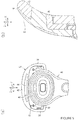
- the proximal portion arcuately bends away from the shaving plane.
- the connecting structure can be provided on the back side of the blade unit opposite to the guard.
- the proximal portion comprises a non-flexible annular rim surrounding a flexible elastic portion to which the connecting structure is attached. This allows the connecting structure, and thereby the blade unit, to pivot.
- the flexible elastic portion may have various configurations to allow, among other things, the connecting structure, and thereby the blade unit, to pivot easily backwards but to resist pivoting forwards.
- the flexible elastic portion has a stepped shape in cross-section.
- the connecting structure is at an off-centred position of the flexible elastic portion relative to the non-flexible annular rim.
- a cap of the flexible elastic portion which is opposite the cap of the blade unit is wider than a front portion of the flexible elastic portion which is opposite the guard of the blade unit.
- Embodiments of the present invention include a blade unit a method of manufacturing a blade unit for a safety razor, the blade unit having a skin-contacting side and a back side opposite the skin-contacting side, the method comprising: providing a blade housing comprising a plurality of blades having respective cutting edges lying in a shaving plane and being arranged to exert a cutting action when moved across a user's skin in a shaving direction; and providing a guard in front of the cutting edges and a cap to the rear of the cutting edges, the guard including an elongate lubricating strip, the cap including a non-flexible concave back portion supporting a convex lubricating pad, the non-flexible concave back portion having a concave surface along the back side of the blade unit, and the convex lubricating pad having a convex skin-contacting surface curved to conform to the arcuate shape of the back portion and a rear edge curved in a single arc shape along its entirety, wherein no separate frame is provided around an
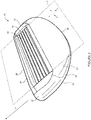
- FIGS 1 to 9 are views of a blade unit and safety razor including the blade unit, according to embodiments.
- the safety razor 8 has a blade unit 10 and a handle 16 (only a part of which is shown in Figure 1 ).
- the blade unit 10 includes a connecting structure 14 that fixes the blade unit 10 to the handle 16, a blade housing 12 and a supporting structure 13 of the blade housing 12.
- the blade housing 12 holds a plurality of blades 18 (five blades in this particular case) having respective cutting edges 20 that lie in a shaving plane P.
- shaving plane generally refers to the place in which the cutting edges lie.
- the direction perpendicular to the shaving plane can be referred to as the thickness direction.
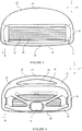
- the supporting structure 13 comprises a cap 24 located behind the blades in a shaving direction d (when assembled) and a guard 30 located in front of the blade in the shaving direction d (when assembled).
- the guard 30 is arranged next to the plurality of blades 18 in the shaving direction on an opposite side to that of the cap 24.
- shaving direction signifies the direction in the shaving plane in which the blade unit is intended to be moved.
- the cap 24 and the guard 30 are connected by side portions 38.
- the supporting structure 13 controls the contact of the cutting edges 20 of the blades 18 with the skin during shaving.
- the cap 24 of the supporting structure 13 comprises a non-flexible concave back portion 26 to which is mounted a convex lubricating pad 22.
- concave and convex are employed herein to signify that the lubricating pad has a convex skin-engaging surface and the back portion has a concave surface along the back.
- non-flexible means that the concave back portion 26 has rigidity to an extent such that it does not bend during ordinary use of the safety razor 8.
- the blade housing and the cap 24, and in particular the lubricating pad 22 and the non-flexible concave back portion 26 can be, for example, adhered, integrated, bonded and/or otherwise attached to each other.
- the radius of curvature of the convex lubricating pad 22 can be set to about 10mm, which is within a preferred range from 5 to 20mm.
- the lubricating pad 22 is in a fixed positional relationship relative to the non-flexible concave back portion 26, the lubricating pad 22 can be deformed by, for example, a compressive force.
- the lubricating pad 22 can return substantially to its shape prior to deformation.
- the non-flexible concave back portion 26 comprises a straight member 40 and an arched member 42 that are connected to each other at respective ends, so as to define a gap 44 in which part of the lubricating pad 22 is disposed when mounted thereon.
- the non-flexible concave back portion 26 and convex lubricating pad 22 meet flush at a rear edge 28 of the cap 24 of the blade unit 10 as can be seen from figure 1 .
- the lubricating pad 22 is curved in an arc shape that extends along substantially the entire rear edge 28 between the side portions 38.
- the guard 30 of the supporting structure 13 comprises a non-flexible back portion 32 on which is mounted an elongate lubricating strip 34.
- the elongate lubricating strip 34 is arranged on and supported by the non-flexible back portion 32.
- the non-flexible back portion 32 and elongate lubricating strip 34 meet flush at a front edge 36 of the guard 30 of the blade unit 10, so that the elongate lubricating strip 34 extends up to the front edge 36 of the guard 30 of the blade unit 10.
- lubricating strip and "lubricating pad” are used to signify that the length-to-width ratio in the shaving plane, i.e., the ratio of the size in a direction parallel to the blades (length direction) to the size in a direction parallel to the shaving direction d (width direction), of the elongate lubricating strip 34 and the convex lubricating pad 22 are different.
- the elongate lubricating strip 34 and convex lubricating pad 22 both extend at least along the length of the exposed cutting edges 20 of the blades 18 and have similar length, though the convex lubricating pad 22 is substantially wider than the elongate lubricating strip 34.
- the elongate lubricating strip 34 has a length-to-width ratio of about 10:1, while the convex lubricating pad 22 has a length to width ratio of about 4:1 at its widest point.
- the composition of the lubricating strip/lubricating pad can include a gliding agent.
- Materials which may be selected as the gliding agent are: PEG-400/1,4-Butanediol/SMDI Copolymer, PEG-115M, PEG 45M, and PEG-5M, or a combination thereof.
- the composition of the lubricating strip/lubricating pad can include an antioxidant agent, for example Tocopherol.
- the composition of the lubricating strip/lubricating pad can include an anti-inflammatory agent, for example aloe barbadensis leaf juice.
- the composition of the lubricating strip/lubricating pad can include a backbone structure.
- composition of the lubricating strip and the composition of the lubricating pad are the same, but this need not be the case.
- the handle 16 has a proximal portion 46 closer to the blade unit 10 and a distal portion 48 (not shown in the Figures) farther from the blade unit 10.
- the connecting structure 14 of the blade unit 10 connects (either fixedly or detachably) to the proximal portion 46 of the handle 16.
- the blade unit 10 may be configured for use with a separate handle or may be permanently attached to the handle 16.
- the proximal portion 46 of the handle 16 also includes a pivot mechanism that allows the blade unit 10 to pivot back-and-forth in a plane perpendicular to the shaving plane P.
- the pivot mechanism can, of course, allow other pivoting motions such as side-to-side.
- the proximal portion 46 arcuately bends away from the shaving plane P, to permit the cap 24 of the blade unit 10 to pivot backwards, i.e., to bend away from the shaving plane, over a large angular range.
- lubricating elements i.e., a lubricating strip and a lubricating pad
- lubricating elements can be a unitary lubricating element which, for example, covers an area of the supporting structure around the blade housing.
- the lubricating strip need not be provided at all.
- the blade housing may comprise more than five blades or fewer than five blades, i.e., the blade housing may comprise at least one blade. When more than one blade is provided, these do not have to lie in a shaving plane, for example the blades could be staggered.
- the shaving aid comprises polymeric material having a lubricating property
- the shaving aid may have, either alternatively or in addition, other, e.g., moisturizing, properties considered beneficial during shaving.
- the shaving aid can take a form other than a pad or a strip.
- the skin-contacting surface of the shaving aid does not have to be smooth but can have, either alternatively or in addition, a finned, holed or other structure.
- the straight and arched member of the cap define one, more than one gap can be provided.
- the cap may define one or more recesses instead of a gap.
- the cap includes a convex lubricating pad having a rear edge that meets flush with a non-flexible concave back portion
- a lubricating pad that extends rearwards (protrudes) from the non-flexible portion to define a rear edge (tip) of the cap may be provided.
- such a lubricating pad 22 can consist of a flexible portion 23 and a non-flexible portion 25, the non-flexible portion 25 of the lubricating pad 22 being arranged on and supported by the non-flexible back portion 26, the flexible portion 23 of the lubricating pad 22 extending rearwards from the non-flexible portion 25 of the lubricating pad 22 beyond the non-flexible back portion 26 to define a rear edge 28 of the rear portion 24 of the blade unit 10, the flexible portion 23 of the lubricating pad 22 being configured to form a convex skin-contacting surface when bending away from the shaving plane P in use.
- no separate element e.g., no separate frame
- the shaving resistance due to contact between the blade unit 10 and the skin surface is lessened during use so that the tactile sensation on the skin surface is improved.
- a back surface 27 of the lubricating pad 22, opposite to the skin-contacting surface can be planar (as shown in Figure 11 ) or can have an inward step (as shown in Figure 12 ).
- the term "inward” means in a direction toward the skin-contacting surface.
- the inward step can be formed at a boundary between the non-flexible portion 25 of the lubricating pad 22 and the flexible portion 23 of the lubricating pad 22. In this way, the lubricating pad 22, and more specifically the flexible portion 23 of the lubricating pad, can have different thicknesses and thus different degrees of flexibility.
- the flexible portion 23 of the lubricating pad 22 can be thicker and therefore relatively more resistant to bending (i.e., less flexible) by contact with a skin surface during use, or thinner and therefore relatively less resistant to bending (i.e., more flexible) by contact with a skin surface during use.
- the flexible portion 23 of the lubricating pad 22 can bend (in a cantilever manner) with respect to the other elements of the blade unit 10 and return substantially to its position and shape prior to contact with the skin surface after use, while the non-flexible portion 25 of the lubricating pad does not substantially bend during use (although the non-flexible portion 25 can be deformed by, for example, a compressive force).
Landscapes
- Life Sciences & Earth Sciences (AREA)
- Forests & Forestry (AREA)
- Engineering & Computer Science (AREA)
- Mechanical Engineering (AREA)
- Dry Shavers And Clippers (AREA)
Claims (13)
- Klingeneinheit (10) für einen Sicherheitsrasierer (8), wobei die Klingeneinheit (10) eine hautberührende Seite und eine der hautberührenden Seite gegenüberliegende Rückseite aufweist, wobei die Klingeneinheit (10) Folgendes umfasst:ein Klingengehäuse (12), das eine Vielzahl von Klingen (18) mit entsprechenden Schneidkanten (20) umfasst, die in einer Rasiereben (P) liegen und so angeordnet sind, dass sie eine Schneidbewegung ausüben, wenn sie über die Haut eines Benutzers in einer Rasierrichtung (d) bewegt werden, undeine Schutzvorrichtung (30) vor den Schneidkanten (20) und einen Aufsatz (24) hinter den Schneidkanten (20),wobei die Schutzvorrichtung (30) einen länglichen Schmierstreifen (34) beinhaltet, undwobei der Aufsatz (24) einen nicht-beweglichen konkaven Rückenabschnitt (26) aufweist, der ein konvexes Schmierkissen (22) trägt, wobei der nicht-bewegliche konkave Rückenabschnitt (26) eine konkave Oberfläche entlang der Rückseite der Klingeneinheit aufweist, und das konvexe Schmierkissen (22) eine konvexe hautberührende Oberfläche aufweist, die gekrümmt ist, um sich an die bogenförmige Form des Rückenabschnitts (26) anzupassen, und eine Hinterkante, die in einer einzigen Bogenform entlang ihrer Gesamtheit gekrümmt ist,wobei kein separater Rahmen um einen äußeren Umfang herum zum Befestigen des konvexen Schmierkissens (22) vorgesehen ist, so dass die Hinterkante des konvexen Schmierkissens bündig mit dem nicht-beweglichen konkaven Rückenabschnitt (26) anschließt und eine glatte, geschmierte Hinterkante (28) der Klingeneinheit (10) bereitstellt.
- Klingeneinheit (10) nach Anspruch 1, wobei die hautberührende Oberfläche des konvexen Schmierkissens (22) größer ist als eine hautberührende Oberfläche des länglichen Schmierstreifens (34).
- Klingeneinheit (10) nach Anspruch 1 oder 2, wobei sich das konvexe Schmierkissen (22) und der längliche Schmierstreifen (34) zusammen entlang mindestens 60%, vorzugsweise mindestens 80% des äußeren Umfangs der Klingeneinheit (10) erstrecken.
- Klingeneinheit (10) nach einem der vorhergehenden Ansprüche, wobei sich das konvexe Schmierkissen (22) entlang mindestens 30%, vorzugsweise mindestens 40% des äußeren Umfangs der Klingeneinheit (10) erstreckt.
- Klingeneinheit (10) nach einem der vorhergehenden Ansprüche, wobei der nicht-bewegliche konkave Rückenabschnitt (26) ein gerades Element (40) und ein gewölbtes Element (42) umfasst, die an jeweiligen Enden miteinander verbunden sind, um mindestens einen Spalt (44) abzugrenzen, in dem ein Teil des konvexen Schmierkissens (22) angeordnet ist.
- Klingeneinheit (10) nach einem der vorhergehenden Ansprüche, wobei der Aufsatz (24) der Klingeneinheit (10) und die Schutzvorrichtung (30) der Klingeneinheit (10) durch Seitenabschnitte (38) der Klingeneinheit (10) verbunden sind, um eine Stützstruktur des Klingengehäuses (12) vorzugeben.
- Klingeneinheit (10) nach Anspruch 6, wobei die Seitenabschnitte (38) einzelne Schmierelemente teilen, die durch den länglichen Schmierstreifen (34) und das konvexe Schmierkissen (22) gebildet werden.
- Sicherheitsrasierer (8) umfassend:eine Klingeneinheit (10) nach einem der vorhergehenden Ansprüche, undeinen Griff (16) mit einem proximalen Abschnitt (46), an dem die Klingeneinheit (10) befestigt ist, und einem distalen Abschnitt (48).
- Sicherheitsrasierer (8) nach Anspruch 8, wobei sich der proximale Abschnitt (46) bogenförmig von der Rasierebene (P) wegbeugt.
- Sicherheitsrasierer (8) nach Anspruch 8 oder 9, wobei der proximale Abschnitt (46) einen nicht-beweglichen ringförmigen Rand umfasst, der einen beweglichen elastischen Abschnitt umgibt, an dem die Verbindungsstruktur (14) befestigt ist.
- Sicherheitsrasierer (8) nach Anspruch 10, wobei der bewegliche elastische Abschnitt im Querschnitt eine Stufenform aufweist.
- Sicherheitsrasierer (8) nach Anspruch 10 oder 11, wobei sich die Verbindungsstruktur (14) in einer exzentrischen Position des beweglichen elastischen Abschnitts im Verhältnis zu dem nicht-beweglichen ringförmigen Rand befindet.
- Verfahren zur Herstellung einer Klingeneinheit (10) für einen Sicherheitsrasierer, wobei die Klingeneinheit (10) eine hautberührende Seite und eine der hautberührenden Seite gegenüberliegende Rückseite aufweist, wobei das Verfahren Folgendes umfasst:Bereitstellen eines Klingengehäuses (12), das eine Vielzahl von Klingen (18) mit entsprechenden Schneidkanten (20) umfasst, die in einer Rasierebene (P) liegen und so angeordnet sind, dass sie eine Schneidbewegung ausüben, wenn sie über die Haut eines Benutzers in einer Rasierrichtung (d) bewegt werden, undBereitstellen einer Schutzvorrichtung (30) vor den Schneidkanten (20) und einem Aufsatz (24) an der Rückseite der Schneidkanten (20),wobei die Schutzvorrichtung (30) einen länglichen Schmierstreifen (34) beinhaltet,wobei der Aufsatz (24) einen nicht-beweglichen konkaven Rückenabschnitt (26) aufweist, der ein konvexes Schmierkissen (22) trägt, wobei der nicht-bewegliche konkave Rückenabschnitt (26) eine konkave Oberfläche entlang der Rückseite der Klingeneinheit (10) hat, und das konvexe Schmierkissen (22) eine konvexe hautberührende Oberfläche aufweist, die gekrümmt ist, um sich an die bogenförmige Form des Rückenabschnitts (26) anzupassen, und eine Hinterkante, die in einer einzelnen Bogenform entlang ihrer Gesamtheit gekrümmt ist,wobei kein separater Rahmen um einen äußeren Umfang herum zum Befestigen des konvexen Schmierkissens (22) vorgesehen ist, so dass die Hinterkante des konvexen Schmierkissens bündig mit dem nicht-beweglichen konkaven Rückenabschnitt (26) anschließt und eine glatte, geschmierte Hinterkante (28) der Klingeneinheit (10) bereitstellt.
Applications Claiming Priority (3)
| Application Number | Priority Date | Filing Date | Title |
|---|---|---|---|
| EP14179264.8A EP2979829B1 (de) | 2014-07-31 | 2014-07-31 | Sicherheitsrasierer und Klingeneinheit für Sicherheitsrasierer |
| EP14179271.3A EP2979830B1 (de) | 2014-07-31 | 2014-07-31 | Sicherheitsrasierer und Klingeneinheit für Sicherheitsrasierer |
| PCT/EP2015/067089 WO2016016152A1 (en) | 2014-07-31 | 2015-07-24 | Safety razor and blade unit for safety razor |
Publications (2)
| Publication Number | Publication Date |
|---|---|
| EP3174675A1 EP3174675A1 (de) | 2017-06-07 |
| EP3174675B1 true EP3174675B1 (de) | 2019-06-19 |
Family
ID=53673035
Family Applications (2)
| Application Number | Title | Priority Date | Filing Date |
|---|---|---|---|
| EP15744541.2A Active EP3174674B1 (de) | 2014-07-31 | 2015-07-24 | Sicherheitsrasierer und klingeneinheit für sicherheitsrasierer |
| EP15744542.0A Active EP3174675B1 (de) | 2014-07-31 | 2015-07-24 | Sicherheitsrasierer und klingeneinheit für sicherheitsrasierer |
Family Applications Before (1)
| Application Number | Title | Priority Date | Filing Date |
|---|---|---|---|
| EP15744541.2A Active EP3174674B1 (de) | 2014-07-31 | 2015-07-24 | Sicherheitsrasierer und klingeneinheit für sicherheitsrasierer |
Country Status (3)
| Country | Link |
|---|---|
| US (2) | US10717202B2 (de) |
| EP (2) | EP3174674B1 (de) |
| WO (2) | WO2016016152A1 (de) |
Families Citing this family (3)
| Publication number | Priority date | Publication date | Assignee | Title |
|---|---|---|---|---|
| DE102013213874A1 (de) * | 2013-07-16 | 2015-02-19 | Beiersdorf Ag | Rasierer mit federnder Halterung |
| DE102013213859A1 (de) * | 2013-07-16 | 2015-01-22 | Beiersdorf Ag | Rasierer in schalenförmiger Gestalt |
| US20160318198A1 (en) * | 2015-04-30 | 2016-11-03 | Larry Brazley | Razor Attachment |
Family Cites Families (16)
| Publication number | Priority date | Publication date | Assignee | Title |
|---|---|---|---|---|
| EP0667813B1 (de) | 1992-11-09 | 1998-04-15 | Warner-Lambert Company | Eingegossenes dynamisches rasiersystem |
| US6185823B1 (en) * | 1995-11-10 | 2001-02-13 | The Gillette Company | Oval frame razor |
| JP4599047B2 (ja) * | 2003-09-30 | 2010-12-15 | 株式会社貝印刃物開発センター | 剃刀 |
| US20050188539A1 (en) * | 2004-02-26 | 2005-09-01 | Prudden John Jr. | Shaving blade unit |
| GB2413980A (en) * | 2004-05-12 | 2005-11-16 | Ian Stephen Bell | Razor head |
| US20060080837A1 (en) * | 2004-10-20 | 2006-04-20 | Robert Johnson | Shaving razors and cartridges |
| JP4977374B2 (ja) | 2006-02-14 | 2012-07-18 | 株式会社貝印刃物開発センター | 剃刀 |
| JP5010896B2 (ja) * | 2006-10-31 | 2012-08-29 | 株式会社貝印刃物開発センター | 剃刀 |
| EP2237932B1 (de) | 2008-01-11 | 2012-04-25 | The Gillette Company | Haarentfernung mit flüssigkeitsausgabe |
| KR20110024234A (ko) | 2009-09-01 | 2011-03-09 | 주식회사 도루코 | 면도기 카트리지 |
| US8407900B2 (en) * | 2010-04-12 | 2013-04-02 | The Gillette Company | Shaving cartridge having mostly elastomeric wings |
| USD698999S1 (en) * | 2012-10-11 | 2014-02-04 | Kai R&D Center Co., Ltd. | Safety razor |
| JP6093551B2 (ja) * | 2012-11-06 | 2017-03-08 | 株式会社貝印刃物開発センター | 剃刀 |
| JP6093550B2 (ja) | 2012-11-06 | 2017-03-08 | 株式会社貝印刃物開発センター | 剃刀 |
| JP6071438B2 (ja) * | 2012-11-06 | 2017-02-01 | 株式会社貝印刃物開発センター | シェービングエイド付き剃刀 |
| US20140150264A1 (en) | 2012-12-05 | 2014-06-05 | Eveready Battery Company Inc. | Razor Handle |
-
2015
- 2015-07-24 US US15/329,289 patent/US10717202B2/en active Active
- 2015-07-24 WO PCT/EP2015/067089 patent/WO2016016152A1/en active Application Filing
- 2015-07-24 EP EP15744541.2A patent/EP3174674B1/de active Active
- 2015-07-24 WO PCT/EP2015/067086 patent/WO2016016151A1/en active Application Filing
- 2015-07-24 US US15/329,286 patent/US10807258B2/en active Active
- 2015-07-24 EP EP15744542.0A patent/EP3174675B1/de active Active
Non-Patent Citations (1)
| Title |
|---|
| None * |
Also Published As
| Publication number | Publication date |
|---|---|
| WO2016016152A1 (en) | 2016-02-04 |
| US20170225344A1 (en) | 2017-08-10 |
| US10807258B2 (en) | 2020-10-20 |
| EP3174675A1 (de) | 2017-06-07 |
| EP3174674A1 (de) | 2017-06-07 |
| US10717202B2 (en) | 2020-07-21 |
| US20180079094A1 (en) | 2018-03-22 |
| EP3174674B1 (de) | 2020-02-19 |
| WO2016016151A1 (en) | 2016-02-04 |
Similar Documents
| Publication | Publication Date | Title |
|---|---|---|
| US20200171688A1 (en) | Safety razor handle | |
| AU2015211201B2 (en) | Safety razor with comb and integrated blade | |
| RU2446938C2 (ru) | Безопасный бритвенный прибор с улучшенным защитным элементом | |
| KR100835449B1 (ko) | 향상된 보호부를 구비한 면도기 및 면도날 유닛 | |
| JP2007519500A (ja) | 双方向シェービング装置 | |
| EP3174675B1 (de) | Sicherheitsrasierer und klingeneinheit für sicherheitsrasierer | |
| EP3453500B1 (de) | Haarentfernungsvorrichtung für schamhaar | |
| US11104018B2 (en) | Safety razor with comb and blade | |
| US10391653B2 (en) | Safety razor and blade unit for safety razor | |
| KR20160146950A (ko) | 면도기 카트리지 보호물 | |
| US11279053B2 (en) | Safety razor and blade unit for safety razor | |
| EP3398734B1 (de) | 2-in-1-sicherheitsrasierer und klingeneinheit für einen 2-in-1-sicherheitsrasierer | |
| EP3398735B1 (de) | 2-in-1 sicherheitsrasiersystem und klingenblock für 2-in-1-sicherheitsrasiersystem | |
| WO2019016163A1 (en) | SAFETY RAZOR HANDLE | |
| EP3453497A1 (de) | Haarentfernungsvorrichtung für schamhaar | |
| EP3453498A1 (de) | Haarentfernungsvorrichtung für schamhaar | |
| US20200198161A1 (en) | Blade unit and lubrapad |
Legal Events
| Date | Code | Title | Description |
|---|---|---|---|
| STAA | Information on the status of an ep patent application or granted ep patent |
Free format text: STATUS: THE INTERNATIONAL PUBLICATION HAS BEEN MADE |
|
| 17P | Request for examination filed |
Effective date: 20161115 |
|
| AK | Designated contracting states |
Kind code of ref document: A1 Designated state(s): AL AT BE BG CH CY CZ DE DK EE ES FI FR GB GR HR HU IE IS IT LI LT LU LV MC MK MT NL NO PL PT RO RS SE SI SK SM TR |
|
| AX | Request for extension of the european patent |
Extension state: BA ME |
|
| PUAI | Public reference made under article 153(3) epc to a published international application that has entered the european phase |
Free format text: ORIGINAL CODE: 0009012 |
|
| STAA | Information on the status of an ep patent application or granted ep patent |
Free format text: STATUS: REQUEST FOR EXAMINATION WAS MADE |
|
| RIN1 | Information on inventor provided before grant (corrected) |
Inventor name: NEUMANN, YVONNE Inventor name: TREU, JENS Inventor name: NAKASUKA, HIROYUKI Inventor name: DRESCHER, PHILIP Inventor name: ZENG, KESEN Inventor name: HAGENS, RALF Inventor name: LESSMANN, MICHAEL |
|
| DAV | Request for validation of the european patent (deleted) | ||
| DAX | Request for extension of the european patent (deleted) | ||
| GRAP | Despatch of communication of intention to grant a patent |
Free format text: ORIGINAL CODE: EPIDOSNIGR1 |
|
| STAA | Information on the status of an ep patent application or granted ep patent |
Free format text: STATUS: GRANT OF PATENT IS INTENDED |
|
| INTG | Intention to grant announced |
Effective date: 20190125 |
|
| RIN1 | Information on inventor provided before grant (corrected) |
Inventor name: LESSMANN, MICHAEL Inventor name: TREU, JENS Inventor name: NAKASUKA, HIROYUKI Inventor name: HAGENS, RALF Inventor name: ZENG, KESEN Inventor name: NEUMANN, YVONNE Inventor name: DRESCHER, PHILIP |
|
| GRAS | Grant fee paid |
Free format text: ORIGINAL CODE: EPIDOSNIGR3 |
|
| GRAA | (expected) grant |
Free format text: ORIGINAL CODE: 0009210 |
|
| STAA | Information on the status of an ep patent application or granted ep patent |
Free format text: STATUS: THE PATENT HAS BEEN GRANTED |
|
| AK | Designated contracting states |
Kind code of ref document: B1 Designated state(s): AL AT BE BG CH CY CZ DE DK EE ES FI FR GB GR HR HU IE IS IT LI LT LU LV MC MK MT NL NO PL PT RO RS SE SI SK SM TR |
|
| REG | Reference to a national code |
Ref country code: GB Ref legal event code: FG4D |
|
| REG | Reference to a national code |
Ref country code: CH Ref legal event code: EP |
|
| REG | Reference to a national code |
Ref country code: IE Ref legal event code: FG4D |
|
| REG | Reference to a national code |
Ref country code: AT Ref legal event code: REF Ref document number: 1144890 Country of ref document: AT Kind code of ref document: T Effective date: 20190715 |
|
| REG | Reference to a national code |
Ref country code: DE Ref legal event code: R096 Ref document number: 602015032281 Country of ref document: DE |
|
| REG | Reference to a national code |
Ref country code: NL Ref legal event code: FP |
|
| PG25 | Lapsed in a contracting state [announced via postgrant information from national office to epo] |
Ref country code: SE Free format text: LAPSE BECAUSE OF FAILURE TO SUBMIT A TRANSLATION OF THE DESCRIPTION OR TO PAY THE FEE WITHIN THE PRESCRIBED TIME-LIMIT Effective date: 20190619 Ref country code: NO Free format text: LAPSE BECAUSE OF FAILURE TO SUBMIT A TRANSLATION OF THE DESCRIPTION OR TO PAY THE FEE WITHIN THE PRESCRIBED TIME-LIMIT Effective date: 20190919 Ref country code: LT Free format text: LAPSE BECAUSE OF FAILURE TO SUBMIT A TRANSLATION OF THE DESCRIPTION OR TO PAY THE FEE WITHIN THE PRESCRIBED TIME-LIMIT Effective date: 20190619 Ref country code: HR Free format text: LAPSE BECAUSE OF FAILURE TO SUBMIT A TRANSLATION OF THE DESCRIPTION OR TO PAY THE FEE WITHIN THE PRESCRIBED TIME-LIMIT Effective date: 20190619 Ref country code: FI Free format text: LAPSE BECAUSE OF FAILURE TO SUBMIT A TRANSLATION OF THE DESCRIPTION OR TO PAY THE FEE WITHIN THE PRESCRIBED TIME-LIMIT Effective date: 20190619 Ref country code: AL Free format text: LAPSE BECAUSE OF FAILURE TO SUBMIT A TRANSLATION OF THE DESCRIPTION OR TO PAY THE FEE WITHIN THE PRESCRIBED TIME-LIMIT Effective date: 20190619 |
|
| REG | Reference to a national code |
Ref country code: LT Ref legal event code: MG4D |
|
| PG25 | Lapsed in a contracting state [announced via postgrant information from national office to epo] |
Ref country code: RS Free format text: LAPSE BECAUSE OF FAILURE TO SUBMIT A TRANSLATION OF THE DESCRIPTION OR TO PAY THE FEE WITHIN THE PRESCRIBED TIME-LIMIT Effective date: 20190619 Ref country code: BG Free format text: LAPSE BECAUSE OF FAILURE TO SUBMIT A TRANSLATION OF THE DESCRIPTION OR TO PAY THE FEE WITHIN THE PRESCRIBED TIME-LIMIT Effective date: 20190919 Ref country code: GR Free format text: LAPSE BECAUSE OF FAILURE TO SUBMIT A TRANSLATION OF THE DESCRIPTION OR TO PAY THE FEE WITHIN THE PRESCRIBED TIME-LIMIT Effective date: 20190920 Ref country code: LV Free format text: LAPSE BECAUSE OF FAILURE TO SUBMIT A TRANSLATION OF THE DESCRIPTION OR TO PAY THE FEE WITHIN THE PRESCRIBED TIME-LIMIT Effective date: 20190619 |
|
| PG25 | Lapsed in a contracting state [announced via postgrant information from national office to epo] |
Ref country code: SK Free format text: LAPSE BECAUSE OF FAILURE TO SUBMIT A TRANSLATION OF THE DESCRIPTION OR TO PAY THE FEE WITHIN THE PRESCRIBED TIME-LIMIT Effective date: 20190619 Ref country code: EE Free format text: LAPSE BECAUSE OF FAILURE TO SUBMIT A TRANSLATION OF THE DESCRIPTION OR TO PAY THE FEE WITHIN THE PRESCRIBED TIME-LIMIT Effective date: 20190619 Ref country code: PT Free format text: LAPSE BECAUSE OF FAILURE TO SUBMIT A TRANSLATION OF THE DESCRIPTION OR TO PAY THE FEE WITHIN THE PRESCRIBED TIME-LIMIT Effective date: 20191021 Ref country code: CZ Free format text: LAPSE BECAUSE OF FAILURE TO SUBMIT A TRANSLATION OF THE DESCRIPTION OR TO PAY THE FEE WITHIN THE PRESCRIBED TIME-LIMIT Effective date: 20190619 Ref country code: RO Free format text: LAPSE BECAUSE OF FAILURE TO SUBMIT A TRANSLATION OF THE DESCRIPTION OR TO PAY THE FEE WITHIN THE PRESCRIBED TIME-LIMIT Effective date: 20190619 |
|
| PG25 | Lapsed in a contracting state [announced via postgrant information from national office to epo] |
Ref country code: IS Free format text: LAPSE BECAUSE OF FAILURE TO SUBMIT A TRANSLATION OF THE DESCRIPTION OR TO PAY THE FEE WITHIN THE PRESCRIBED TIME-LIMIT Effective date: 20191019 Ref country code: SM Free format text: LAPSE BECAUSE OF FAILURE TO SUBMIT A TRANSLATION OF THE DESCRIPTION OR TO PAY THE FEE WITHIN THE PRESCRIBED TIME-LIMIT Effective date: 20190619 Ref country code: IT Free format text: LAPSE BECAUSE OF FAILURE TO SUBMIT A TRANSLATION OF THE DESCRIPTION OR TO PAY THE FEE WITHIN THE PRESCRIBED TIME-LIMIT Effective date: 20190619 |
|
| PG25 | Lapsed in a contracting state [announced via postgrant information from national office to epo] |
Ref country code: MC Free format text: LAPSE BECAUSE OF FAILURE TO SUBMIT A TRANSLATION OF THE DESCRIPTION OR TO PAY THE FEE WITHIN THE PRESCRIBED TIME-LIMIT Effective date: 20190619 Ref country code: TR Free format text: LAPSE BECAUSE OF FAILURE TO SUBMIT A TRANSLATION OF THE DESCRIPTION OR TO PAY THE FEE WITHIN THE PRESCRIBED TIME-LIMIT Effective date: 20190619 |
|
| REG | Reference to a national code |
Ref country code: BE Ref legal event code: MM Effective date: 20190731 |
|
| PG25 | Lapsed in a contracting state [announced via postgrant information from national office to epo] |
Ref country code: PL Free format text: LAPSE BECAUSE OF FAILURE TO SUBMIT A TRANSLATION OF THE DESCRIPTION OR TO PAY THE FEE WITHIN THE PRESCRIBED TIME-LIMIT Effective date: 20190619 Ref country code: DK Free format text: LAPSE BECAUSE OF FAILURE TO SUBMIT A TRANSLATION OF THE DESCRIPTION OR TO PAY THE FEE WITHIN THE PRESCRIBED TIME-LIMIT Effective date: 20190619 |
|
| PG25 | Lapsed in a contracting state [announced via postgrant information from national office to epo] |
Ref country code: LU Free format text: LAPSE BECAUSE OF NON-PAYMENT OF DUE FEES Effective date: 20190724 Ref country code: IS Free format text: LAPSE BECAUSE OF FAILURE TO SUBMIT A TRANSLATION OF THE DESCRIPTION OR TO PAY THE FEE WITHIN THE PRESCRIBED TIME-LIMIT Effective date: 20200224 Ref country code: BE Free format text: LAPSE BECAUSE OF NON-PAYMENT OF DUE FEES Effective date: 20190731 |
|
| REG | Reference to a national code |
Ref country code: DE Ref legal event code: R097 Ref document number: 602015032281 Country of ref document: DE |
|
| PLBE | No opposition filed within time limit |
Free format text: ORIGINAL CODE: 0009261 |
|
| STAA | Information on the status of an ep patent application or granted ep patent |
Free format text: STATUS: NO OPPOSITION FILED WITHIN TIME LIMIT |
|
| PG2D | Information on lapse in contracting state deleted |
Ref country code: IS |
|
| PG25 | Lapsed in a contracting state [announced via postgrant information from national office to epo] |
Ref country code: IE Free format text: LAPSE BECAUSE OF NON-PAYMENT OF DUE FEES Effective date: 20190724 |
|
| 26N | No opposition filed |
Effective date: 20200603 |
|
| PG25 | Lapsed in a contracting state [announced via postgrant information from national office to epo] |
Ref country code: SI Free format text: LAPSE BECAUSE OF FAILURE TO SUBMIT A TRANSLATION OF THE DESCRIPTION OR TO PAY THE FEE WITHIN THE PRESCRIBED TIME-LIMIT Effective date: 20190619 |
|
| PG25 | Lapsed in a contracting state [announced via postgrant information from national office to epo] |
Ref country code: ES Free format text: LAPSE BECAUSE OF FAILURE TO SUBMIT A TRANSLATION OF THE DESCRIPTION OR TO PAY THE FEE WITHIN THE PRESCRIBED TIME-LIMIT Effective date: 20190619 |
|
| PG25 | Lapsed in a contracting state [announced via postgrant information from national office to epo] |
Ref country code: CY Free format text: LAPSE BECAUSE OF FAILURE TO SUBMIT A TRANSLATION OF THE DESCRIPTION OR TO PAY THE FEE WITHIN THE PRESCRIBED TIME-LIMIT Effective date: 20190619 |
|
| PG25 | Lapsed in a contracting state [announced via postgrant information from national office to epo] |
Ref country code: MT Free format text: LAPSE BECAUSE OF FAILURE TO SUBMIT A TRANSLATION OF THE DESCRIPTION OR TO PAY THE FEE WITHIN THE PRESCRIBED TIME-LIMIT Effective date: 20190619 Ref country code: HU Free format text: LAPSE BECAUSE OF FAILURE TO SUBMIT A TRANSLATION OF THE DESCRIPTION OR TO PAY THE FEE WITHIN THE PRESCRIBED TIME-LIMIT; INVALID AB INITIO Effective date: 20150724 |
|
| REG | Reference to a national code |
Ref country code: AT Ref legal event code: UEP Ref document number: 1144890 Country of ref document: AT Kind code of ref document: T Effective date: 20190619 |
|
| REG | Reference to a national code |
Ref country code: GB Ref legal event code: 732E Free format text: REGISTERED BETWEEN 20220331 AND 20220406 |
|
| REG | Reference to a national code |
Ref country code: NL Ref legal event code: PD Owner name: KAI R&D CENTER CO., LTD.; JP Free format text: DETAILS ASSIGNMENT: CHANGE OF OWNER(S), ASSIGNMENT; FORMER OWNER NAME: BEIERSDORF AKTIENGESELLSCHAFT Effective date: 20220325 |
|
| REG | Reference to a national code |
Ref country code: DE Ref legal event code: R081 Ref document number: 602015032281 Country of ref document: DE Owner name: KAI R&D CENTER CO., LTD., SEKI-SHI, JP Free format text: FORMER OWNER: BEIERSDORF AKTIENGESELLSCHAFT, 20253 HAMBURG, DE |
|
| REG | Reference to a national code |
Ref country code: AT Ref legal event code: PC Ref document number: 1144890 Country of ref document: AT Kind code of ref document: T Owner name: KAI R&D CENTER CO., LTD., JP Effective date: 20220509 |
|
| PG25 | Lapsed in a contracting state [announced via postgrant information from national office to epo] |
Ref country code: MK Free format text: LAPSE BECAUSE OF FAILURE TO SUBMIT A TRANSLATION OF THE DESCRIPTION OR TO PAY THE FEE WITHIN THE PRESCRIBED TIME-LIMIT Effective date: 20190619 |
|
| PGFP | Annual fee paid to national office [announced via postgrant information from national office to epo] |
Ref country code: NL Payment date: 20230614 Year of fee payment: 9 |
|
| PGFP | Annual fee paid to national office [announced via postgrant information from national office to epo] |
Ref country code: GB Payment date: 20230601 Year of fee payment: 9 Ref country code: CH Payment date: 20230801 Year of fee payment: 9 Ref country code: AT Payment date: 20230626 Year of fee payment: 9 |
|
| PGFP | Annual fee paid to national office [announced via postgrant information from national office to epo] |
Ref country code: DE Payment date: 20230531 Year of fee payment: 9 |
|
| PGFP | Annual fee paid to national office [announced via postgrant information from national office to epo] |
Ref country code: FR Payment date: 20231027 Year of fee payment: 9 |