EP3174613B2 - Élément de séparation d'eau muni d'électrodes de détection d'eau - Google Patents
Élément de séparation d'eau muni d'électrodes de détection d'eau Download PDFInfo
- Publication number
- EP3174613B2 EP3174613B2 EP15744171.8A EP15744171A EP3174613B2 EP 3174613 B2 EP3174613 B2 EP 3174613B2 EP 15744171 A EP15744171 A EP 15744171A EP 3174613 B2 EP3174613 B2 EP 3174613B2
- Authority
- EP
- European Patent Office
- Prior art keywords
- water
- separating element
- electrodes
- electrode
- filter housing
- Prior art date
- Legal status (The legal status is an assumption and is not a legal conclusion. Google has not performed a legal analysis and makes no representation as to the accuracy of the status listed.)
- Active
Links
- XLYOFNOQVPJJNP-UHFFFAOYSA-N water Substances O XLYOFNOQVPJJNP-UHFFFAOYSA-N 0.000 title claims description 243
- 238000001514 detection method Methods 0.000 title description 5
- 238000000926 separation method Methods 0.000 claims description 100
- 239000000446 fuel Substances 0.000 claims description 13
- 238000004062 sedimentation Methods 0.000 claims description 12
- 239000004020 conductor Substances 0.000 description 10
- 239000002245 particle Substances 0.000 description 9
- 239000002184 metal Substances 0.000 description 7
- 238000010079 rubber tapping Methods 0.000 description 7
- 238000009434 installation Methods 0.000 description 4
- 238000007789 sealing Methods 0.000 description 2
- 238000010276 construction Methods 0.000 description 1
- 238000011109 contamination Methods 0.000 description 1
- 230000007423 decrease Effects 0.000 description 1
- 230000002950 deficient Effects 0.000 description 1
- 238000011161 development Methods 0.000 description 1
- 230000018109 developmental process Effects 0.000 description 1
- 238000001914 filtration Methods 0.000 description 1
- 239000011888 foil Substances 0.000 description 1
- 238000010438 heat treatment Methods 0.000 description 1
- 239000012212 insulator Substances 0.000 description 1
- 230000000717 retained effect Effects 0.000 description 1
Images


Classifications
-
- B—PERFORMING OPERATIONS; TRANSPORTING
- B01—PHYSICAL OR CHEMICAL PROCESSES OR APPARATUS IN GENERAL
- B01D—SEPARATION
- B01D36/00—Filter circuits or combinations of filters with other separating devices
- B01D36/003—Filters in combination with devices for the removal of liquids
- B01D36/005—Liquid level sensing means, e.g. for water in gasoil-filters
-
- B—PERFORMING OPERATIONS; TRANSPORTING
- B01—PHYSICAL OR CHEMICAL PROCESSES OR APPARATUS IN GENERAL
- B01D—SEPARATION
- B01D29/00—Filters with filtering elements stationary during filtration, e.g. pressure or suction filters, not covered by groups B01D24/00 - B01D27/00; Filtering elements therefor
- B01D29/11—Filters with filtering elements stationary during filtration, e.g. pressure or suction filters, not covered by groups B01D24/00 - B01D27/00; Filtering elements therefor with bag, cage, hose, tube, sleeve or like filtering elements
- B01D29/31—Self-supporting filtering elements
-
- F—MECHANICAL ENGINEERING; LIGHTING; HEATING; WEAPONS; BLASTING
- F02—COMBUSTION ENGINES; HOT-GAS OR COMBUSTION-PRODUCT ENGINE PLANTS
- F02M—SUPPLYING COMBUSTION ENGINES IN GENERAL WITH COMBUSTIBLE MIXTURES OR CONSTITUENTS THEREOF
- F02M37/00—Apparatus or systems for feeding liquid fuel from storage containers to carburettors or fuel-injection apparatus; Arrangements for purifying liquid fuel specially adapted for, or arranged on, internal-combustion engines
- F02M37/22—Arrangements for purifying liquid fuel specially adapted for, or arranged on, internal-combustion engines, e.g. arrangements in the feeding system
- F02M37/24—Arrangements for purifying liquid fuel specially adapted for, or arranged on, internal-combustion engines, e.g. arrangements in the feeding system characterised by water separating means
- F02M37/26—Arrangements for purifying liquid fuel specially adapted for, or arranged on, internal-combustion engines, e.g. arrangements in the feeding system characterised by water separating means with water detection means
-
- F—MECHANICAL ENGINEERING; LIGHTING; HEATING; WEAPONS; BLASTING
- F02—COMBUSTION ENGINES; HOT-GAS OR COMBUSTION-PRODUCT ENGINE PLANTS
- F02M—SUPPLYING COMBUSTION ENGINES IN GENERAL WITH COMBUSTIBLE MIXTURES OR CONSTITUENTS THEREOF
- F02M37/00—Apparatus or systems for feeding liquid fuel from storage containers to carburettors or fuel-injection apparatus; Arrangements for purifying liquid fuel specially adapted for, or arranged on, internal-combustion engines
- F02M37/22—Arrangements for purifying liquid fuel specially adapted for, or arranged on, internal-combustion engines, e.g. arrangements in the feeding system
- F02M37/32—Arrangements for purifying liquid fuel specially adapted for, or arranged on, internal-combustion engines, e.g. arrangements in the feeding system characterised by filters or filter arrangements
- F02M37/34—Arrangements for purifying liquid fuel specially adapted for, or arranged on, internal-combustion engines, e.g. arrangements in the feeding system characterised by filters or filter arrangements by the filter structure, e.g. honeycomb, mesh or fibrous
-
- B—PERFORMING OPERATIONS; TRANSPORTING
- B01—PHYSICAL OR CHEMICAL PROCESSES OR APPARATUS IN GENERAL
- B01D—SEPARATION
- B01D2201/00—Details relating to filtering apparatus
- B01D2201/29—Filter cartridge constructions
- B01D2201/291—End caps
-
- B—PERFORMING OPERATIONS; TRANSPORTING
- B01—PHYSICAL OR CHEMICAL PROCESSES OR APPARATUS IN GENERAL
- B01D—SEPARATION
- B01D2201/00—Details relating to filtering apparatus
- B01D2201/29—Filter cartridge constructions
- B01D2201/291—End caps
- B01D2201/298—End caps common to at least two filtering elements
-
- B—PERFORMING OPERATIONS; TRANSPORTING
- B01—PHYSICAL OR CHEMICAL PROCESSES OR APPARATUS IN GENERAL
- B01D—SEPARATION
- B01D2201/00—Details relating to filtering apparatus
- B01D2201/40—Special measures for connecting different parts of the filter
- B01D2201/4084—Snap or Seeger ring connecting means
Definitions
- the invention relates to a water separating element for a fuel filter of a motor vehicle.
- a water separator for filtering fuel in a motor vehicle is from DE 10 2011 078 362 A1 known.
- the well-known water separating element is designed to be water separating in two stages. It has a particle filter medium and a final separator screen for separating water. The separated water collects in a water collection chamber. If the backwater level in the water collection chamber is too high, this is detected by a water level sensor, the electrodes of which are guided in a support rod of the fuel filter.
- the WO 2010/049208 A1 discloses a filter device with a water sensor, which is formed in a structural unit with a heating track of the filter device.
- the water sensor has sensor pins that can be coupled to a plug connector via electrical contacts.
- the object of the invention is therefore to enable permanently reliable water detection in a fuel filter.
- the object of the invention is thus achieved by a water separating element for a fuel filter of a motor vehicle, the water separating element having two water level electrodes for detecting backwater in a water collection chamber of the fuel filter and the water level electrodes being electrically contactable via two contact electrodes, the contact electrodes being electrically conductively connected to the water level electrodes .
- the water level electrodes Due to the arrangement of the water level electrodes on the water separation element, the water level electrodes are renewed when the water separation element is changed.
- the water detection can thus be permanently reliable.
- the water separating element preferably comprises a particle filter medium which is supported on a center tube.
- the water separation element is designed in the form of a filter element.
- the water separation element can have a sedimentation opening for water separation.
- the sedimentation opening is preferably formed on an end plate of the water separation element.
- the sedimentation opening is particularly preferably designed in the form of a sedimentation gap.
- the water separation takes place with a particularly high degree of efficiency if the water separation element has a coalescing medium, in particular in the form of a fleece.
- the water separation element also has a final separator screen for water separation, the final separator screen being arranged or formed in a filter holder, the filter holder being arranged or formed radially to the longitudinal axis of the water separation element.
- the water separation rate is significantly increased by the final separator screen.
- a first contact electrode can be ring-shaped radially to the longitudinal axis of the water separator.
- Both contact electrodes are preferably ring-shaped radially to the longitudinal axis of the water separator. Due to the ring-shaped contact electrodes, the portafilter can be mounted with practically any rotation about the longitudinal axis of the water separator, with the electrical connection to the water level electrodes being maintained in any case.
- the water level electrodes can each be formed in one piece or in one piece with the contact electrodes. In this way, the electrical connection between the water level electrodes and the contact electrodes can be securely maintained.
- the contact electrodes can be arranged or formed at least partially on an end plate of the water separation element. As a result, the contact electrodes can easily be contacted by tapping electrodes arranged on the filter housing.
- At least one connecting line between a water level electrode and a contact electrode can run in the filter holder.
- a connecting line in a central tube get lost.
- a first water level electrode is preferably connected via an electrical connecting line to a first contact electrode lying on the outside with respect to the longitudinal axis of the water separation element, and a second water level electrode is connected to a second contact electrode lying on the inside with respect to the longitudinal axis of the water separating element, with the connecting line running at least partially embedded in the end plate between the second contact electrode and an underside of the end plate .
- the water level electrodes can have essentially the same distance from the longitudinal axis of the water separating element, without a short circuit occurring between the water level electrodes. Sections of the end plate serve as an insulator between the second contact electrode and the connecting line.
- the portafilter is and the central tube can be connected to the end plate of the water separating element via a snap connection, with the water level electrodes being electrically connected to the contact electrodes via an interruptible resilient contact when the portafilter is snapped to the end plate.
- the portafilter or the central tube is particularly easy to assemble due to the snap-in connection.
- the contact electrodes are arranged or formed in an interior of the filter holder, wherein the contact electrodes can each be contacted by an at least partially spring-elastic tapping electrode and the tapping electrodes are arranged or formed at least in sections directed radially outwards on a central tube element of the filter.
- Such an arrangement results in a water separation element that is particularly easy to assemble, with the electrical connection being routed from the water level electrodes arranged or formed “below” on the filter holder via the tapping electrodes and further “up” via the central tube element.
- the portafilter is particularly preferably designed to be closed on its underside pointing towards the water level electrodes in the area of the central tube element.
- the lower part of the interior of the portafilter i.e. the part of the interior of the portafilter that can be aligned towards the water collection space, is preferably of closed design.
- a particularly compact and easily mountable construction of the water separating element can be achieved if the particle filter medium, the coalescer medium, the sedimentation opening and the final separator screen are arranged one after the other radially to the longitudinal axis of the water separating element.
- the water separation element can have an electrically conductive short-circuit bridge for electrically bridging at least two filter housing electrodes arranged or formed on an inside of the filter housing. Correct installation of the water separation element in a filter housing can be ensured by the electrically conductive short-circuit bridge. Furthermore, such a short-circuit bridge can be used to ensure that only original water separation elements are used in the filter housing, thereby avoiding damage to the engine due to defective replica water separation elements.
- the invention further relates to a filter with a water separation element as described above and a filter housing that has a water collection space, the water level electrodes protruding at least partially into the water collection space when the water separation element is inserted in the filter housing.
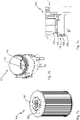
- Fig. 1a 1 shows a first filter 10 in the form of a fuel filter of a motor vehicle (not shown) with a first filter housing 12 shown only schematically by dashed lines.
- the first water separation element 14 has a particle filter medium 16 , a coalescer medium 18 , a sedimentation opening 20 and a final separator screen 22 .
- a dot-dash arrow 28 shows the path of the fuel through the particle filter medium 16, the coalescer medium 18, the sedimentation opening 20 and the end separator screen 22. It can be seen that the particle filter medium 16, the coalescer medium 18, the sedimentation opening 20 and the end separator screen 22 radially to one Wasserabscheideelementlijnsachse 30 are arranged.
- the first water separating element 14 is designed essentially axially symmetrically to the longitudinal axis 30 of the water separating element.
- the water can be effectively removed from the fuel by the coalescer medium 18, the sedimentation opening 20 and the final separator screen 22 in order to avoid engine damage.
- the separated water collects in a water collection space 32 of the first filter housing 12.
- a water level in the water collection space 32 that is too high is detected by water level electrodes 34, 36.
- the water level electrodes 34, 36 and the final separator screen are arranged on a screen carrier 38.
- the water level electrodes 34, 36 can be contacted electrically via contact electrodes 40, 42.
- FIG. 1b shows a partial view of the first water separating element 14.
- FIG Fig. 1b It can be seen that the radially outer, first contact electrode 40 is electrically connected to the first water level electrode 34 via an electrical connecting line 44 .
- the connecting line 44 runs embedded in an end plate 46 of the first water separating element 14.
- the first contact electrode 40 and the electrical connecting line 44 are designed in one piece.
- the connecting line 44 and the first water level electrode 34 can be formed in one piece.
- the connecting line 44 and the first water level electrode 34 are electrically connected via a first resilient contact 48 .
- the portafilter 38 can be connected to the end plate 46 of the first water separating element 14 via a latching connection 50 . As a result, the portafilter 38 can be mounted particularly easily. When the filter holder 38 is mounted, an electrically conductive connection between the first water level electrode 34 and the first contact electrode 40 is produced at the same time by the first spring-elastic contact 48 .
- FIG 1c shows a further partial view of the first water separation element 14.
- FIG 1c It can be seen that the radially inner, second contact electrode 42 is electrically connected to the second water level electrode 36 via a second spring-elastic contact 52 .
- an electrically conductive connection between the second water level electrode 36 and the second contact electrode 42 is simultaneously produced by the second spring-elastic contact 52.
- the second water separating element 54 is identical to the first water separating element 14.
- water level electrodes 56, 58 are not diametrically opposed like the water level electrodes 34, 36 (see FIG Fig. 1a ), but spaced at right angles to a longitudinal axis 60 of the water separator.
- a filter holder 62 is formed in one piece with an end plate 64
- the first water level electrode 56 is formed in one piece with a first contact electrode 66
- the second water level electrode 58 is formed in one piece with a second contact electrode 68 .
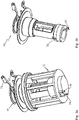
- Figure 3a 12 shows a central tube element 70 of a fuel filter and a screen carrier 72 of a third water separation element.
- the center tube element 70 is not part of a water separation element.
- the portafilter 72 has water level electrodes 74,76.
- the water level electrodes 74, 76 are electrically connected to pickup electrodes 78, 80, respectively.
- the sieve carrier 72 also has a final separator sieve on its outer circumference, which is not shown for reasons of clarity.
- Figure 3b shows the center tube element 70. From Figure 3b It can be seen that the tapping electrodes 78, 80 are designed to be resilient in sections at one end. The pickup electrodes 78, 80 are used to establish an electrical connection to the water level electrodes 74, 76 (see Figure 3a ).
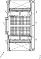
- FIG. 12 shows the establishment of this electrical connection in a partially sectioned view of the central tube element 70 and the portafilter 72 according to FIG Figure 3a .
- the water level electrodes 74, 76 (of which in 3c only the first water level electrode 74 is shown) are electrically connected to annular contact electrodes 82, 84, respectively.
- the water level electrodes 74, 76 (see Figure 3a ) are each formed in one piece with the contact electrodes 82, 84.
- the contact electrodes 82, 84 are each contacted by the at least partially resilient tapping electrodes 78, 80, which are arranged in sections on the central tube element 70 in a radially outward direction and press against the contact electrodes 82, 84 with their resilient section.
- the portafilter 72 is at its to the water level electrodes 74, 76 (see Figure 3a ) pointing underside 90 in the area of the central tube element 70 is closed.
- a seal in particular a sealing ring, between the central tube element and the portafilter can be dispensed with.
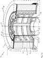
- FIG. 4a shows a fourth water separation element 110.
- the fourth water separation element 110 has a particle filter medium 112.
- the particle filter medium 112 is designed as a pleated filter.
- the particulate filter media 112 is bordered by a first endplate 114 and a second endplate 116 .
- a first water separating element electrode 120 and a second water separating element electrode 122 are arranged on the outwardly facing surface 118 of the first end plate 114 .
- the first water separating element electrode 120 is connected to the second water separating element electrode 122 by means of a short-circuit bridge 124 in the form of an electrical conductor.
- the electrical conductor is in the form of a metal strip.
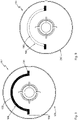
- FIG Figure 4b shows a second filter housing 126 for accommodating the fourth water separation element 110 according to FIG Figure 4a .
- the second filter housing 126 has a filter housing inside 128 .
- the filter housing inside 128 faces the fourth water separation element 110 when the fourth water separation element 110 is inserted into the second filter housing 126 .
- a first filter housing electrode 130 and a second filter housing electrode 132 are arranged on the filter housing inside 128 .
- the first filter housing electrode 130 is radially symmetrical to the longitudinal axis of the second filter housing 126 .
- the second filter housing electrode 132 is radially symmetrical to the longitudinal axis of the second filter housing 126 .
- the second filter housing electrode 132 is configured concentrically to the first filter housing electrode 130 .
- the first filter housing electrode 130 and the second filter housing electrode 132 are designed essentially in the shape of a tire or ring with a common center point.
- the first filter housing electrode 130 consists of an electrically conductive material, preferably metal.
- the second filter housing electrode 132 consists of an electrically conductive material, preferably metal.
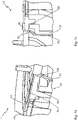
- Figure 4c shows a second filter 134.
- the second filter 134 has the second filter housing 126 with it - in comparison to Figure 4a Fourth water separation element 110 shown "upside down".
- the expression “upside down” means a rotation through 180°, with the axis of rotation running perpendicular to the longitudinal axis of the fourth water separation element 110 during this rotation.
- the first water separating element electrode 120 and the second water separating element electrode 122 are designed in a curved manner in sections.
- the first water separating element electrode 120 and the second water separating element electrode 122 therefore have resilient properties.
- the first water separation element electrode 120 is in electrical and mechanical contact with the first filter housing electrode 130 when the fourth water separation element 110 is installed in the second filter housing 126.
- the second water separation element electrode 122 is in electrical and mechanical contact with the second filter housing electrode when the fourth water separation element 110 is installed in the second filter housing 126 132
- a voltage can be applied between the first filter housing electrode 130 and the second filter housing electrode 132 . Then a stream flows from the first filter housing electrode 130 to the first water separating element electrode 120, via the short-circuit bridge 124 (see Fig. 1a ) to the second water separation element electrode 122 and further to the second filter housing electrode 132. Depending on the polarity of the applied voltage, the current can also flow in the opposite direction. Only when the fourth water separation element 110 is installed correctly in the second filter housing 126 does the current flow come about. By measuring the current flow, conclusions can be drawn about the correct installation of the fourth water separation element 110 in the second filter housing 126 .
- the circuit described above can also have a known resistance. By measuring this resistance, it is easy to judge whether the fourth water separation element 110 is an original part or an imitation. Furthermore, the circuit described above can have a known capacitance and/or inductance. By applying an AC voltage between the first filter housing electrode 130 and the second filter housing electrode 132 and measuring the resulting current, it is possible to assess particularly precisely whether an imitation of the fourth water separation element 110 is involved.
- a controller (not shown) detects that an imitation is present or that the fourth water separation element 110 is not correctly installed in the second filter housing 126, this can be indicated to a user visually or acoustically. If the second filter 134 is used in a motor vehicle, the engine control can be interrupted in order to prevent damage to the motor vehicle.
- FIG. 5a shows a fifth water separation element 136.
- the fifth water separation element 136 corresponds to the fourth water separation element 110 according to FIG Figure 4a .
- the fifth water separating element 136 has a short-circuit bridge 138 which comprises both the first water separating element electrode and the second water separating element electrode, the water separating element electrodes being connected via an electrical conductor.
- the first water separation element electrode and the second water separation element electrode represent different sections of the short-circuit bridge 138 .
- the short-circuit bridge 138 is connected to a water separation element body 142 of the fifth water separation element 136 via an elastic water separation element part 140 .
- the short-circuit bar 138 is made of an electrically conductive material, preferably metal.
- FIG. 5b shows a third filter 144.
- the third filter 144 has the fifth water separating element 136, which - compared to Figure 4a shown "upside down" - is installed in a third filter housing 146 .
- the third filter housing 146 has a first filter housing electrode 148 and a second filter housing electrode 150 .
- a voltage can be applied between the first filter housing electrode 148 and the second filter housing electrode 150 .
- the filter housing electrodes 148, 150 are electrically bridged by the electrically connected water separation element electrodes of the short-circuit bridge 138. This allows the correct seating of the fifth water separation element 136 in the third filter housing 146 to be checked. Furthermore, it can be checked whether the fifth water separation element 136 is a reproduction.
- the filter housing electrodes 148, 150 can be configured radially symmetrically to the longitudinal axis of the third filter housing 146 in order to be able to insert the fifth water separation element 136 into the third filter housing 146 rotated about its longitudinal axis as desired.
- the first filter housing electrode 148 and/or the second filter housing electrode 150 can be designed in the form of an electrically conductive plate, in particular a metal plate.
- the second filter housing 126 according to FIG Figure 4b in combination with the fifth water separation element 136 according to Figure 5a be used.
- FIG. 6a shows a sixth water separation element 152.
- the sixth water separation element 152 corresponds to the fifth water separation element 136 according to FIG Figure 5a .
- the sixth water separation element 152 has a short-circuit bridge 154 in the form of a ring.
- Figure 6b 15 shows a fourth filter housing 156.
- the fourth filter housing 156 has a first filter housing electrode 158 and a second filter housing electrode 160.
- FIG. 1 shows a first filter housing electrode 158 and a second filter housing electrode 160.
- Figure 6c 14 shows a fourth filter 162.
- the fourth filter 162 has the fourth filter housing 156 according to FIG Figure 6b on.
- the sixth water separation element 152 (according to Figure 6a ) of the fourth filter 162 is shown "upside down" in the fourth filter housing 156.
- the first filter housing electrode 158 is electrically short-circuited to the second filter housing electrode 160 via the short-circuit bar 154 .
- the filter housing electrodes 158, 160 are in the form of spring pins.
- the spring pins have elastic filter housing parts (not shown). A particularly reliable electrical contact is achieved by the spring pins.
- FIG. 7a shows a seventh water separation element 164.
- the seventh water separation element 164 corresponds to the sixth water separation element 152 according to FIG Figure 6a .
- the seventh water separating element 164 has a first water separating element electrode ring 166, which annularly surrounds an end plate 168 of the seventh water separating element 164 on its outer circumference.
- the water separating element electrode ring 166 comprises in different sections a first water separating element electrode, a second water separating element electrode and a direct electrical connection in the form of a short-circuit bridge between these water separating element electrodes.
- Figure 7b 12 shows a fifth filter housing 170.
- the fifth filter housing 170 has a first filter housing electrode 172 and a second filter housing electrode 174.
- Figure 7c 12 shows a fifth filter 176.
- the fifth filter 176 includes the fifth filter housing 170 according to FIG Figure 7b and the seventh water separation element 164 according to FIG Figure 7a .
- the seventh water separation element 164 is shown "upside down" in the fifth filter housing 170 .
- the water separation element electrode ring 166 bridges the filter housing electrodes 172, 174 (see Figure 7b ; in Figure 7c only the first filter housing electrode 172 is visible).
- Out Figure 7c It can be seen that the first filter housing electrode 172 is connected to a filter housing body 180 of the fifth filter housing 176 via an elastic filter housing part 178 .
- the electrical connection between the filter housing electrodes 172, 174 and the water separating element electrodes of the water separating element electrode ring 166 is thus retained even after the seventh water separating element 164 has been installed and removed several times.
- the second filter housing electrode (not shown) is also connected to the filter housing body 180 of the fifth filter housing 176 via an elastic filter housing part (not shown).
- the eighth water separation element 182 has an end plate 184.
- FIG. A shorting bar in the form of a metal contact strip 186 is formed on the end plate 184 .
- the contact strip 186 can be in the form of a metal foil, for example.
- the contact strip 186 has a first water separating element electrode 188 and a second water separating element electrode 190 .
- the water separating element electrodes 188 , 190 are directly electrically connected via an ohmic conductor 192 .
- the ohmic conductor 192 is formed as a portion of the contact strip 186 .
- FIG. 9 shows a ninth water separating element 194.
- the ninth water separating element 194 corresponds to the eighth water separating element 182.
- a section of a contact strip 198 designed as an ohmic conductor 196 is embedded in the end plate 200 and covered by the plastic of an end plate 200. This makes the resistive conductor 196 less susceptible to damage.
- the invention preferably relates to a multi-stage water separation element.
- the water separation element preferably has a particle filter medium, a coalescer medium, a sedimentation opening and a filter holder with a final separator filter.
- Two water level electrodes are preferably arranged on the portafilter.
- the water level electrodes are designed in such a way that they protrude into a water collection space of a filter housing when the water separating element is installed in the filter housing.
- Each water level electrode can be contacted via a contact electrode that is preferably essentially ring-shaped.
- the contact electrodes can be contacted by tapping electrodes of a central tube element.
- the portafilter preferably has a closed receiving shaft for the central tube element in the longitudinal direction of the water separating element toward the water level electrodes, so that no seal has to be provided between the central tube element and the portafilter.
Claims (14)
- Élément de séparation d'eau (14, 54, 110, 136, 152, 164, 182, 194) pour un filtre à carburant (10, 134, 144, 162, 176) d'un véhicule automobile,dans lequel l'élément de séparation d'eau (14, 54, 110, 136, 152, 164, 182, 194) présente deux électrodes de niveau d'eau (34, 36, 56, 58, 74, 76) pour détecter l'eau de retenue dans un collecteur d'eau (32) du filtre à carburant (10), 134, 144, 162, 176) et que les électrodes de niveau d'eau (34, 36, 56, 58, 74, 76) peuvent être mises en contact électriquement par deux électrodes de contact (40, 42, 66, 68, 82, 84), les électrodes de contact (40, 42, 66, 68, 82, 84) étant reliées de manière électroconductrice aux électrodes de niveau d'eau (34, 36, 56, 58, 74, 76),dans lequel l'élément de séparation d'eau (14, 54, 110, 136, 152, 164, 182, 194) présente un tamis de séparation final (22) pour séparer l'eau, le tamis de séparation final (22) étant disposé ou réalisé dans un porte-tamis (38, 62, 72), le porte-tamis (38, 62, 72) étant disposé ou réalisé de manière radiale par rapport à l'axe longitudinal de l'élément de séparation d'eau (30, 60),dans lequel le porte-tamis (38) est relié à la plaque d'extrémité (46) de l'élément de séparation d'eau (14) par une liaison par encliquetage (50), les électrodes de niveau d'eau (34, 36), lorsque le porte-tamis (38) est enclenché à la plaque d'extrémité (46), étant reliées chacune électriquement aux électrodes de contact (40, 42) par un contact élastique interruptible (48, 52).
- Élément de séparation d'eau selon la revendication 1, dans lequel l'élément de séparation d'eau (14, 54, 110, 136, 152, 164, 182, 194) présente un milieu filtrant particulaire (16, 112) soutenu sur un tube central.
- Élément de séparation d'eau selon la revendication 1 ou 2, dans lequel l'élément de séparation d'eau (14, 54, 110, 136, 152, 164, 182, 194) présente une ouverture de sédimentation pour séparer l'eau.
- Élément de séparation d'eau selon l'une des revendications précédentes, dans lequel l'élément de séparation d'eau (14, 54, 110, 136, 152, 164, 182, 194) présente un milieu coalescent (18) pour séparer l'eau.
- Élément de séparation d'eau (14, 54, 110, 136, 152, 164, 182, 194) selon l'une des revendications précédentes, dans lequel une première électrode de contact (40, 42, 66, 68, 82, 84) est réalisée en forme d'anneau de manière radiale par rapport à l'axe longitudinal de l'élément de séparation d'eau (30, 60) .
- Élément de séparation d'eau (14, 54, 110, 136, 152, 164, 182, 194) selon la revendication 5, dans lequel une seconde électrode de contact (40, 42, 66, 68, 82, 84) est réalisée en forme d'anneau de manière radiale par rapport à l'axe longitudinal de l'élément de séparation d'eau (30, 60).
- Élément de séparation d'eau selon l'une des revendications précédentes, dans lequel les électrodes de contact (40, 42, 66, 68) sont, au moins en partie, disposées ou réalisées sur une plaque d'extrémité (46, 64) de l'élément de séparation d'eau (14, 54).
- Élément de séparation d'eau selon l'une des revendications précédentes, dans lequel les lignes de raccordement entre les électrodes de niveau d'eau (34, 36, 56, 58, 74, 76) et les électrodes de contact (40, 42, 66, 68, 82, 84) s'étendent, au moins sur certaines sections, dans un tube central et/ou dans un porte-tamis (38, 62, 72).
- Élément de séparation d'eau selon la revendication 7 ou 8, dans lequel une première électrode de niveau d'eau (34, 56) est reliée par une ligne de raccordement électrique (44) à une première électrode de contact (40, 66) située à l'extérieur par rapport à l'axe longitudinal de l'élément de séparation d'eau (30, 60) et une seconde électrode de niveau d'eau (36, 58) reliée à une seconde électrode de contact (42, 68) qui est située à l'intérieur par rapport à l'axe longitudinal de l'élément de séparation d'eau (30, 60), la ligne de raccordement (44) s'étendant, au moins en partie incorporée dans la plaque d'extrémité (46, 64), entre la seconde électrode de contact (42, 68) et une face inférieure de la plaque d'extrémité (46, 64).
- Élément de séparation d'eau selon l'une des revendications 1 à 9, dans lequel les électrodes de contact (82, 84) sont disposées ou réalisées dans un espace intérieur du porte-tamis (72), les électrodes de contact (82, 84) pouvant être mises en contact chacune par une électrode de prélèvement (78, 80), au moins partiellement élastique, et les électrodes de prélèvement (78, 80) étant disposées ou réalisées, au moins sur certaines sections, en sens radial vers l'extérieur sur un élément de tube central (70) du filtre.
- Élément de séparation d'eau selon la revendication 10, dans lequel le porte-tamis (72) est réalisé fermé sur sa face inférieure (90) dirigée vers les électrodes de niveau d'eau (74, 76) dans la zone de l'élément de tube central (70).
- Élément de séparation d'eau selon l'une des revendications précédentes en combinaison avec la revendication 4, dans lequel le milieu filtrant particulaire (16), le milieu coalescent (18), l'ouverture de sédimentation (20) et le tamis de séparation final (22) sont disposés l'un après l'autre de manière radiale par rapport à l'axe longitudinal de l'élément de séparation d'eau (30, 60).
- Élément de séparation d'eau selon l'une des revendications précédentes, l'élément de séparation d'eau (110, 136, 152, 164, 182, 194) présentant un pont de court-circuit électroconducteur (124, 138 , 154), pour un pontage électrique des électrodes de boîtier de filtre (130, 132, 148, 150, 158, 160, 172, 174), au moins au nombre de deux, disposées ou réalisées sur une face interne (128) du boîtier de filtre (126, 146, 156, 170).
- Filtre (10, 134, 144, 162, 176) présentant un élément de séparation d'eau (14, 54, 110, 136, 152, 164, 182, 194) selon l'une des revendications précédentes et un boîtier de filtre (12, 126, 146, 156, 170) présentant un collecteur d'eau (32), les électrodes de niveau d'eau (34, 36, 56, 58, 74, 76) faisant saillie, au moins en partie, dans le collecteur d'eau (32) lorsque l'élément de séparation d'eau (14, 54, 110, 136, 152, 164, 182, 194) est inséré dans le boîtier du filtre (12, 126, 146, 156, 170).
Applications Claiming Priority (2)
| Application Number | Priority Date | Filing Date | Title |
|---|---|---|---|
| DE102014010997.6A DE102014010997B4 (de) | 2014-07-29 | 2014-07-29 | Wasserabscheideelement mit Wasserdetektionselektroden |
| PCT/EP2015/067119 WO2016016172A1 (fr) | 2014-07-29 | 2015-07-27 | Élément de séparation d'eau muni d'électrodes de détection d'eau |
Publications (3)
| Publication Number | Publication Date |
|---|---|
| EP3174613A1 EP3174613A1 (fr) | 2017-06-07 |
| EP3174613B1 EP3174613B1 (fr) | 2018-12-26 |
| EP3174613B2 true EP3174613B2 (fr) | 2023-01-25 |
Family
ID=53761362
Family Applications (1)
| Application Number | Title | Priority Date | Filing Date |
|---|---|---|---|
| EP15744171.8A Active EP3174613B2 (fr) | 2014-07-29 | 2015-07-27 | Élément de séparation d'eau muni d'électrodes de détection d'eau |
Country Status (5)
| Country | Link |
|---|---|
| US (1) | US10150068B2 (fr) |
| EP (1) | EP3174613B2 (fr) |
| CN (1) | CN106536016A (fr) |
| DE (1) | DE102014010997B4 (fr) |
| WO (1) | WO2016016172A1 (fr) |
Families Citing this family (11)
| Publication number | Priority date | Publication date | Assignee | Title |
|---|---|---|---|---|
| DE102015012473A1 (de) | 2015-09-29 | 2017-03-30 | Mann + Hummel Gmbh | Filterelement mit Zentralelement für ein Filtersystem |
| CN107228037B (zh) | 2016-03-23 | 2020-10-27 | 上海欧菲滤清器有限公司 | 燃油滤清器 |
| IT201600082909A1 (it) * | 2016-08-05 | 2018-02-05 | Ufi Innovation Center S R L | Assieme cartuccia con elemento anulare di contatto |
| DE102017002119A1 (de) | 2017-03-08 | 2018-09-13 | Mann+Hummel Gmbh | Filterelement mit Zentralelement für ein Filtersystem |
| ES2684611B1 (es) * | 2017-03-30 | 2019-06-21 | Cebi Electromechanical Components Spain S A | Sensor de agua para detección de agua en filtros de gasóleo |
| DE102017004813A1 (de) * | 2017-05-19 | 2018-11-22 | Mann+Hummel Gmbh | Filtersystem mit Zentralelement und Siebfilter |
| IT201800009624A1 (it) * | 2018-10-19 | 2020-04-19 | Ufi Filters Spa | Filtro carburante |
| DE102018133569A1 (de) * | 2018-12-21 | 2020-06-25 | Hengst Se | Filtereinsatz für einen Kraftstofffilter mit dreistufiger Filtration |
| DE102018133331A1 (de) | 2018-12-21 | 2020-06-25 | Hengst Se | Filtereinsatz mit Wasserstandsensoren |
| CN112443437B (zh) * | 2019-08-30 | 2024-01-23 | 上海索菲玛汽车滤清器有限公司 | 燃油滤清器 |
| DE102019215867A1 (de) | 2019-10-15 | 2021-04-15 | Mahle International Gmbh | Filtereinrichtung |
Citations (3)
| Publication number | Priority date | Publication date | Assignee | Title |
|---|---|---|---|---|
| WO2015040479A2 (fr) † | 2013-09-19 | 2015-03-26 | Ufi Filters S.P.A. | Groupe filtrant équipé d'un détecteur de présence d'eau dans un carburant diesel |
| WO2015128711A1 (fr) † | 2014-02-27 | 2015-09-03 | Ufi Filters S.P.A. | Cartouche filtrante et groupe de filtres muni d'un capteur d'eau fixé au noyau du filtre |
| WO2015193574A1 (fr) † | 2014-06-17 | 2015-12-23 | Filtrauto | Filtre à carburant séparateur d'eau et élément filtrant avec détecteur d'eau. |
Family Cites Families (17)
| Publication number | Priority date | Publication date | Assignee | Title |
|---|---|---|---|---|
| DE3829190C1 (fr) | 1988-08-29 | 1989-11-23 | Knecht Filterwerke Gmbh, 7000 Stuttgart, De | |
| FR2844461B1 (fr) | 2002-09-17 | 2004-11-26 | Filtrauto | Filtre a gazole comportant un detecteur d'eau |
| DE102007031382A1 (de) * | 2007-06-26 | 2009-01-08 | Hengst Gmbh & Co.Kg | Kraftstofffilter mit Filtererkennung |
| DE102008043197A1 (de) * | 2008-10-27 | 2010-04-29 | Robert Bosch Gmbh | Filtereinrichtung mit einem Wassersensor |
| DE202009000429U1 (de) | 2009-01-12 | 2010-05-27 | Mann + Hummel Gmbh | Kraftstofffilter mit Wasseraustragsrohr |
| DE102009016601A1 (de) | 2009-04-08 | 2010-10-21 | Mann + Hummel Gmbh | Filtereinrichtung für Fluide, insbesondere für Kraftstoffe |
| DE102009029413A1 (de) | 2009-09-14 | 2011-03-17 | Robert Bosch Gmbh | Filtereinrichtung mit einer Heizung und einem Wassersensor |
| DE102011078362A1 (de) * | 2011-06-29 | 2013-01-03 | Mahle International Gmbh | Kraftstofffilter |
| DE102011081141A1 (de) * | 2011-08-17 | 2013-02-21 | Robert Bosch Gmbh | Filtereinrichtung mit einem Filtergehäuse und einem Entwässerer |
| TWI462514B (zh) | 2011-09-29 | 2014-11-21 | Inst Information Industry | 分時多工正交分頻多工分佈式天線系統、基地台及遠端存取組件 |
| DE102011120638A1 (de) * | 2011-12-09 | 2013-06-13 | Mann + Hummel Gmbh | Filterelement eines Kraftstoffilters und Verfahren zur Herstellung eines solchen |
| US9279780B2 (en) * | 2012-04-30 | 2016-03-08 | Cummins Filtration Ip, Inc. | Filters, filter assemblies, filter systems and methods for identifying installation of qualified filter elements |
| DE102012221890A1 (de) | 2012-11-29 | 2014-06-05 | Robert Bosch Gmbh | Filtereinrichtung mit einem Filtergehäuse |
| KR20140089620A (ko) * | 2012-12-14 | 2014-07-16 | 암페놀센싱코리아 유한회사 | 디젤연료필터용 워터센서 프로브 |
| DE102013211209B4 (de) * | 2013-06-14 | 2016-02-25 | Robert Bosch Gmbh | Filtereinsatz für einen Flüssigkeitsfilter, insbesondere für einen Kraftstofffilter |
| DE102013221209B4 (de) | 2013-10-18 | 2019-09-26 | Fraunhofer-Gesellschaft zur Förderung der angewandten Forschung e.V. | Siliconhydrogel, Verfahren zu dessen Herstellung, Formteil hieraus sowie Verwendungszwecke |
| US9724628B2 (en) * | 2014-07-11 | 2017-08-08 | Caterpillar Inc. | Fuel water separator having filter and sensor |
-
2014
- 2014-07-29 DE DE102014010997.6A patent/DE102014010997B4/de active Active
-
2015
- 2015-07-27 CN CN201580040775.4A patent/CN106536016A/zh active Pending
- 2015-07-27 EP EP15744171.8A patent/EP3174613B2/fr active Active
- 2015-07-27 WO PCT/EP2015/067119 patent/WO2016016172A1/fr active Application Filing
-
2017
- 2017-01-27 US US15/418,026 patent/US10150068B2/en active Active
Patent Citations (3)
| Publication number | Priority date | Publication date | Assignee | Title |
|---|---|---|---|---|
| WO2015040479A2 (fr) † | 2013-09-19 | 2015-03-26 | Ufi Filters S.P.A. | Groupe filtrant équipé d'un détecteur de présence d'eau dans un carburant diesel |
| WO2015128711A1 (fr) † | 2014-02-27 | 2015-09-03 | Ufi Filters S.P.A. | Cartouche filtrante et groupe de filtres muni d'un capteur d'eau fixé au noyau du filtre |
| WO2015193574A1 (fr) † | 2014-06-17 | 2015-12-23 | Filtrauto | Filtre à carburant séparateur d'eau et élément filtrant avec détecteur d'eau. |
Also Published As
| Publication number | Publication date |
|---|---|
| US10150068B2 (en) | 2018-12-11 |
| EP3174613B1 (fr) | 2018-12-26 |
| CN106536016A (zh) | 2017-03-22 |
| WO2016016172A1 (fr) | 2016-02-04 |
| DE102014010997B4 (de) | 2016-08-11 |
| US20170157542A1 (en) | 2017-06-08 |
| EP3174613A1 (fr) | 2017-06-07 |
| DE102014010997A1 (de) | 2016-02-04 |
Similar Documents
| Publication | Publication Date | Title |
|---|---|---|
| EP3174613B2 (fr) | Élément de séparation d'eau muni d'électrodes de détection d'eau | |
| EP2164594A2 (fr) | Filtre à carburant doté d'un détecteur | |
| EP3552710B1 (fr) | Unité filtrante électrostatique et dispositif d'extraction pourvu d'unité filtrante électrostatique | |
| EP3227161B1 (fr) | Système de capteur pour un volant de vehicule, volant avec un tel sytème et procédé pour opérer un tel système | |
| EP3227163B1 (fr) | Volant pour un véhicule avec un capteur système et procédé pour détecter une main humaine dans une zone de prise du volant | |
| DE102013211209B4 (de) | Filtereinsatz für einen Flüssigkeitsfilter, insbesondere für einen Kraftstofffilter | |
| DE102016121453A1 (de) | Fehleruntersuchungssystem, das eine Unterscheidung zwischen einem Leckstromfehler und einem Kurzschlussfehler ermöglicht | |
| WO2014095419A1 (fr) | Dispositif permettant de définir ou de surveiller une grandeur de processus d'un milieu dans une conduite | |
| WO2016046229A1 (fr) | Capteur de suie | |
| DE3703695C2 (fr) | ||
| DE102018201224A1 (de) | Steckbare Hochspannungsdurchführung und elektrisches Gerät mit der steckbaren Hochspannungsdurchführung | |
| DE202019005847U1 (de) | Kraftstofffilter mit Erhitzer zum Abführen elektrostatischer Aufladungen | |
| EP2828672A1 (fr) | Capteur électronique pour batterie | |
| EP3717807B1 (fr) | Dispositif de joint d'étanchéité | |
| DE4009358C2 (de) | Steckbuchse | |
| DE102018205629A1 (de) | Hochvoltbatterie für ein Kraftfahrzeug | |
| DE102016223097B4 (de) | Dichtungsscheibe für ein Wälzlager | |
| DE102007027411A1 (de) | Überspannungsableiteranordnung | |
| WO2015090787A1 (fr) | Dispositif pour augmenter la sécurité au cours de l'utilisation de systèmes de batteries | |
| DE102018133331A1 (de) | Filtereinsatz mit Wasserstandsensoren | |
| WO2016150694A1 (fr) | Filtre à carburant | |
| DE102015009624A1 (de) | Elektrisch kontaktierbares Filterelement | |
| DE102006012189B4 (de) | Kondensator mit einem Widerstandselement | |
| EP1063380B1 (fr) | Dispositif de sécurité pour bord de porte | |
| DE102013219268A1 (de) | Feststoffisolierte Stromschiene |
Legal Events
| Date | Code | Title | Description |
|---|---|---|---|
| STAA | Information on the status of an ep patent application or granted ep patent |
Free format text: STATUS: THE INTERNATIONAL PUBLICATION HAS BEEN MADE |
|
| 17P | Request for examination filed |
Effective date: 20161214 |
|
| AK | Designated contracting states |
Kind code of ref document: A1 Designated state(s): AL AT BE BG CH CY CZ DE DK EE ES FI FR GB GR HR HU IE IS IT LI LT LU LV MC MK MT NL NO PL PT RO RS SE SI SK SM TR |
|
| AX | Request for extension of the european patent |
Extension state: BA ME |
|
| PUAI | Public reference made under article 153(3) epc to a published international application that has entered the european phase |
Free format text: ORIGINAL CODE: 0009012 |
|
| STAA | Information on the status of an ep patent application or granted ep patent |
Free format text: STATUS: REQUEST FOR EXAMINATION WAS MADE |
|
| DAV | Request for validation of the european patent (deleted) | ||
| DAX | Request for extension of the european patent (deleted) | ||
| GRAP | Despatch of communication of intention to grant a patent |
Free format text: ORIGINAL CODE: EPIDOSNIGR1 |
|
| STAA | Information on the status of an ep patent application or granted ep patent |
Free format text: STATUS: GRANT OF PATENT IS INTENDED |
|
| INTG | Intention to grant announced |
Effective date: 20180815 |
|
| GRAS | Grant fee paid |
Free format text: ORIGINAL CODE: EPIDOSNIGR3 |
|
| GRAA | (expected) grant |
Free format text: ORIGINAL CODE: 0009210 |
|
| STAA | Information on the status of an ep patent application or granted ep patent |
Free format text: STATUS: THE PATENT HAS BEEN GRANTED |
|
| RAP1 | Party data changed (applicant data changed or rights of an application transferred) |
Owner name: MANN+HUMMEL GMBH |
|
| AK | Designated contracting states |
Kind code of ref document: B1 Designated state(s): AL AT BE BG CH CY CZ DE DK EE ES FI FR GB GR HR HU IE IS IT LI LT LU LV MC MK MT NL NO PL PT RO RS SE SI SK SM TR |
|
| REG | Reference to a national code |
Ref country code: GB Ref legal event code: FG4D Free format text: NOT ENGLISH |
|
| REG | Reference to a national code |
Ref country code: CH Ref legal event code: EP |
|
| REG | Reference to a national code |
Ref country code: AT Ref legal event code: REF Ref document number: 1080623 Country of ref document: AT Kind code of ref document: T Effective date: 20190115 |
|
| REG | Reference to a national code |
Ref country code: IE Ref legal event code: FG4D Free format text: LANGUAGE OF EP DOCUMENT: GERMAN |
|
| REG | Reference to a national code |
Ref country code: DE Ref legal event code: R096 Ref document number: 502015007444 Country of ref document: DE |
|
| PG25 | Lapsed in a contracting state [announced via postgrant information from national office to epo] |
Ref country code: LV Free format text: LAPSE BECAUSE OF FAILURE TO SUBMIT A TRANSLATION OF THE DESCRIPTION OR TO PAY THE FEE WITHIN THE PRESCRIBED TIME-LIMIT Effective date: 20181226 Ref country code: FI Free format text: LAPSE BECAUSE OF FAILURE TO SUBMIT A TRANSLATION OF THE DESCRIPTION OR TO PAY THE FEE WITHIN THE PRESCRIBED TIME-LIMIT Effective date: 20181226 Ref country code: LT Free format text: LAPSE BECAUSE OF FAILURE TO SUBMIT A TRANSLATION OF THE DESCRIPTION OR TO PAY THE FEE WITHIN THE PRESCRIBED TIME-LIMIT Effective date: 20181226 Ref country code: NO Free format text: LAPSE BECAUSE OF FAILURE TO SUBMIT A TRANSLATION OF THE DESCRIPTION OR TO PAY THE FEE WITHIN THE PRESCRIBED TIME-LIMIT Effective date: 20190326 Ref country code: HR Free format text: LAPSE BECAUSE OF FAILURE TO SUBMIT A TRANSLATION OF THE DESCRIPTION OR TO PAY THE FEE WITHIN THE PRESCRIBED TIME-LIMIT Effective date: 20181226 Ref country code: BG Free format text: LAPSE BECAUSE OF FAILURE TO SUBMIT A TRANSLATION OF THE DESCRIPTION OR TO PAY THE FEE WITHIN THE PRESCRIBED TIME-LIMIT Effective date: 20190326 |
|
| REG | Reference to a national code |
Ref country code: NL Ref legal event code: MP Effective date: 20181226 |
|
| REG | Reference to a national code |
Ref country code: LT Ref legal event code: MG4D |
|
| PG25 | Lapsed in a contracting state [announced via postgrant information from national office to epo] |
Ref country code: SE Free format text: LAPSE BECAUSE OF FAILURE TO SUBMIT A TRANSLATION OF THE DESCRIPTION OR TO PAY THE FEE WITHIN THE PRESCRIBED TIME-LIMIT Effective date: 20181226 Ref country code: AL Free format text: LAPSE BECAUSE OF FAILURE TO SUBMIT A TRANSLATION OF THE DESCRIPTION OR TO PAY THE FEE WITHIN THE PRESCRIBED TIME-LIMIT Effective date: 20181226 Ref country code: GR Free format text: LAPSE BECAUSE OF FAILURE TO SUBMIT A TRANSLATION OF THE DESCRIPTION OR TO PAY THE FEE WITHIN THE PRESCRIBED TIME-LIMIT Effective date: 20190327 Ref country code: RS Free format text: LAPSE BECAUSE OF FAILURE TO SUBMIT A TRANSLATION OF THE DESCRIPTION OR TO PAY THE FEE WITHIN THE PRESCRIBED TIME-LIMIT Effective date: 20181226 |
|
| PG25 | Lapsed in a contracting state [announced via postgrant information from national office to epo] |
Ref country code: NL Free format text: LAPSE BECAUSE OF FAILURE TO SUBMIT A TRANSLATION OF THE DESCRIPTION OR TO PAY THE FEE WITHIN THE PRESCRIBED TIME-LIMIT Effective date: 20181226 |
|
| PG25 | Lapsed in a contracting state [announced via postgrant information from national office to epo] |
Ref country code: PT Free format text: LAPSE BECAUSE OF FAILURE TO SUBMIT A TRANSLATION OF THE DESCRIPTION OR TO PAY THE FEE WITHIN THE PRESCRIBED TIME-LIMIT Effective date: 20190426 Ref country code: CZ Free format text: LAPSE BECAUSE OF FAILURE TO SUBMIT A TRANSLATION OF THE DESCRIPTION OR TO PAY THE FEE WITHIN THE PRESCRIBED TIME-LIMIT Effective date: 20181226 Ref country code: ES Free format text: LAPSE BECAUSE OF FAILURE TO SUBMIT A TRANSLATION OF THE DESCRIPTION OR TO PAY THE FEE WITHIN THE PRESCRIBED TIME-LIMIT Effective date: 20181226 Ref country code: PL Free format text: LAPSE BECAUSE OF FAILURE TO SUBMIT A TRANSLATION OF THE DESCRIPTION OR TO PAY THE FEE WITHIN THE PRESCRIBED TIME-LIMIT Effective date: 20181226 Ref country code: IT Free format text: LAPSE BECAUSE OF FAILURE TO SUBMIT A TRANSLATION OF THE DESCRIPTION OR TO PAY THE FEE WITHIN THE PRESCRIBED TIME-LIMIT Effective date: 20181226 |
|
| PG25 | Lapsed in a contracting state [announced via postgrant information from national office to epo] |
Ref country code: SM Free format text: LAPSE BECAUSE OF FAILURE TO SUBMIT A TRANSLATION OF THE DESCRIPTION OR TO PAY THE FEE WITHIN THE PRESCRIBED TIME-LIMIT Effective date: 20181226 Ref country code: EE Free format text: LAPSE BECAUSE OF FAILURE TO SUBMIT A TRANSLATION OF THE DESCRIPTION OR TO PAY THE FEE WITHIN THE PRESCRIBED TIME-LIMIT Effective date: 20181226 Ref country code: SK Free format text: LAPSE BECAUSE OF FAILURE TO SUBMIT A TRANSLATION OF THE DESCRIPTION OR TO PAY THE FEE WITHIN THE PRESCRIBED TIME-LIMIT Effective date: 20181226 Ref country code: IS Free format text: LAPSE BECAUSE OF FAILURE TO SUBMIT A TRANSLATION OF THE DESCRIPTION OR TO PAY THE FEE WITHIN THE PRESCRIBED TIME-LIMIT Effective date: 20190426 Ref country code: RO Free format text: LAPSE BECAUSE OF FAILURE TO SUBMIT A TRANSLATION OF THE DESCRIPTION OR TO PAY THE FEE WITHIN THE PRESCRIBED TIME-LIMIT Effective date: 20181226 |
|
| REG | Reference to a national code |
Ref country code: DE Ref legal event code: R026 Ref document number: 502015007444 Country of ref document: DE |
|
| PLBI | Opposition filed |
Free format text: ORIGINAL CODE: 0009260 |
|
| PLAX | Notice of opposition and request to file observation + time limit sent |
Free format text: ORIGINAL CODE: EPIDOSNOBS2 |
|
| 26 | Opposition filed |
Opponent name: HAECKEL, STEFAN Effective date: 20190920 |
|
| PG25 | Lapsed in a contracting state [announced via postgrant information from national office to epo] |
Ref country code: DK Free format text: LAPSE BECAUSE OF FAILURE TO SUBMIT A TRANSLATION OF THE DESCRIPTION OR TO PAY THE FEE WITHIN THE PRESCRIBED TIME-LIMIT Effective date: 20181226 |
|
| PLBB | Reply of patent proprietor to notice(s) of opposition received |
Free format text: ORIGINAL CODE: EPIDOSNOBS3 |
|
| PG25 | Lapsed in a contracting state [announced via postgrant information from national office to epo] |
Ref country code: SI Free format text: LAPSE BECAUSE OF FAILURE TO SUBMIT A TRANSLATION OF THE DESCRIPTION OR TO PAY THE FEE WITHIN THE PRESCRIBED TIME-LIMIT Effective date: 20181226 Ref country code: MC Free format text: LAPSE BECAUSE OF FAILURE TO SUBMIT A TRANSLATION OF THE DESCRIPTION OR TO PAY THE FEE WITHIN THE PRESCRIBED TIME-LIMIT Effective date: 20181226 |
|
| REG | Reference to a national code |
Ref country code: CH Ref legal event code: PL |
|
| GBPC | Gb: european patent ceased through non-payment of renewal fee |
Effective date: 20190727 |
|
| PG25 | Lapsed in a contracting state [announced via postgrant information from national office to epo] |
Ref country code: TR Free format text: LAPSE BECAUSE OF FAILURE TO SUBMIT A TRANSLATION OF THE DESCRIPTION OR TO PAY THE FEE WITHIN THE PRESCRIBED TIME-LIMIT Effective date: 20181226 |
|
| REG | Reference to a national code |
Ref country code: BE Ref legal event code: MM Effective date: 20190731 |
|
| PG25 | Lapsed in a contracting state [announced via postgrant information from national office to epo] |
Ref country code: GB Free format text: LAPSE BECAUSE OF NON-PAYMENT OF DUE FEES Effective date: 20190727 |
|
| PG25 | Lapsed in a contracting state [announced via postgrant information from national office to epo] |
Ref country code: CH Free format text: LAPSE BECAUSE OF NON-PAYMENT OF DUE FEES Effective date: 20190731 Ref country code: BE Free format text: LAPSE BECAUSE OF NON-PAYMENT OF DUE FEES Effective date: 20190731 Ref country code: LU Free format text: LAPSE BECAUSE OF NON-PAYMENT OF DUE FEES Effective date: 20190727 Ref country code: LI Free format text: LAPSE BECAUSE OF NON-PAYMENT OF DUE FEES Effective date: 20190731 |
|
| PG25 | Lapsed in a contracting state [announced via postgrant information from national office to epo] |
Ref country code: IE Free format text: LAPSE BECAUSE OF NON-PAYMENT OF DUE FEES Effective date: 20190727 |
|
| RAP4 | Party data changed (patent owner data changed or rights of a patent transferred) |
Owner name: MANN+HUMMEL GMBH |
|
| APAH | Appeal reference modified |
Free format text: ORIGINAL CODE: EPIDOSCREFNO |
|
| APBM | Appeal reference recorded |
Free format text: ORIGINAL CODE: EPIDOSNREFNO |
|
| APBP | Date of receipt of notice of appeal recorded |
Free format text: ORIGINAL CODE: EPIDOSNNOA2O |
|
| PG25 | Lapsed in a contracting state [announced via postgrant information from national office to epo] |
Ref country code: CY Free format text: LAPSE BECAUSE OF FAILURE TO SUBMIT A TRANSLATION OF THE DESCRIPTION OR TO PAY THE FEE WITHIN THE PRESCRIBED TIME-LIMIT Effective date: 20181226 |
|
| APBQ | Date of receipt of statement of grounds of appeal recorded |
Free format text: ORIGINAL CODE: EPIDOSNNOA3O |
|
| PG25 | Lapsed in a contracting state [announced via postgrant information from national office to epo] |
Ref country code: HU Free format text: LAPSE BECAUSE OF FAILURE TO SUBMIT A TRANSLATION OF THE DESCRIPTION OR TO PAY THE FEE WITHIN THE PRESCRIBED TIME-LIMIT; INVALID AB INITIO Effective date: 20150727 Ref country code: MT Free format text: LAPSE BECAUSE OF FAILURE TO SUBMIT A TRANSLATION OF THE DESCRIPTION OR TO PAY THE FEE WITHIN THE PRESCRIBED TIME-LIMIT Effective date: 20181226 |
|
| REG | Reference to a national code |
Ref country code: AT Ref legal event code: MM01 Ref document number: 1080623 Country of ref document: AT Kind code of ref document: T Effective date: 20200727 |
|
| PG25 | Lapsed in a contracting state [announced via postgrant information from national office to epo] |
Ref country code: AT Free format text: LAPSE BECAUSE OF NON-PAYMENT OF DUE FEES Effective date: 20200727 |
|
| PG25 | Lapsed in a contracting state [announced via postgrant information from national office to epo] |
Ref country code: MK Free format text: LAPSE BECAUSE OF FAILURE TO SUBMIT A TRANSLATION OF THE DESCRIPTION OR TO PAY THE FEE WITHIN THE PRESCRIBED TIME-LIMIT Effective date: 20181226 |
|
| APBU | Appeal procedure closed |
Free format text: ORIGINAL CODE: EPIDOSNNOA9O |
|
| PUAH | Patent maintained in amended form |
Free format text: ORIGINAL CODE: 0009272 |
|
| STAA | Information on the status of an ep patent application or granted ep patent |
Free format text: STATUS: PATENT MAINTAINED AS AMENDED |
|
| 27A | Patent maintained in amended form |
Effective date: 20230125 |
|
| AK | Designated contracting states |
Kind code of ref document: B2 Designated state(s): AL AT BE BG CH CY CZ DE DK EE ES FI FR GB GR HR HU IE IS IT LI LT LU LV MC MK MT NL NO PL PT RO RS SE SI SK SM TR |
|
| REG | Reference to a national code |
Ref country code: DE Ref legal event code: R102 Ref document number: 502015007444 Country of ref document: DE |
|
| P01 | Opt-out of the competence of the unified patent court (upc) registered |
Effective date: 20230530 |
|
| PGFP | Annual fee paid to national office [announced via postgrant information from national office to epo] |
Ref country code: FR Payment date: 20230726 Year of fee payment: 9 Ref country code: DE Payment date: 20230719 Year of fee payment: 9 |