EP3174465B1 - Verfahren und vorrichtung zur protonencomputertomographie - Google Patents
Verfahren und vorrichtung zur protonencomputertomographie Download PDFInfo
- Publication number
- EP3174465B1 EP3174465B1 EP15747199.6A EP15747199A EP3174465B1 EP 3174465 B1 EP3174465 B1 EP 3174465B1 EP 15747199 A EP15747199 A EP 15747199A EP 3174465 B1 EP3174465 B1 EP 3174465B1
- Authority
- EP
- European Patent Office
- Prior art keywords
- image reconstruction
- matrix
- image
- proton
- particles
- Prior art date
- Legal status (The legal status is an assumption and is not a legal conclusion. Google has not performed a legal analysis and makes no representation as to the accuracy of the status listed.)
- Active
Links
Images



Classifications
-
- A—HUMAN NECESSITIES
- A61—MEDICAL OR VETERINARY SCIENCE; HYGIENE
- A61B—DIAGNOSIS; SURGERY; IDENTIFICATION
- A61B6/00—Apparatus or devices for radiation diagnosis; Apparatus or devices for radiation diagnosis combined with radiation therapy equipment
- A61B6/02—Arrangements for diagnosis sequentially in different planes; Stereoscopic radiation diagnosis
- A61B6/03—Computed tomography [CT]
- A61B6/032—Transmission computed tomography [CT]
-
- G—PHYSICS
- G06—COMPUTING OR CALCULATING; COUNTING
- G06T—IMAGE DATA PROCESSING OR GENERATION, IN GENERAL
- G06T12/00—Tomographic reconstruction from projections
-
- A—HUMAN NECESSITIES
- A61—MEDICAL OR VETERINARY SCIENCE; HYGIENE
- A61B—DIAGNOSIS; SURGERY; IDENTIFICATION
- A61B6/00—Apparatus or devices for radiation diagnosis; Apparatus or devices for radiation diagnosis combined with radiation therapy equipment
- A61B6/42—Arrangements for detecting radiation specially adapted for radiation diagnosis
- A61B6/4208—Arrangements for detecting radiation specially adapted for radiation diagnosis characterised by using a particular type of detector
- A61B6/4258—Arrangements for detecting radiation specially adapted for radiation diagnosis characterised by using a particular type of detector for detecting non x-ray radiation, e.g. gamma radiation
-
- A—HUMAN NECESSITIES
- A61—MEDICAL OR VETERINARY SCIENCE; HYGIENE
- A61B—DIAGNOSIS; SURGERY; IDENTIFICATION
- A61B6/00—Apparatus or devices for radiation diagnosis; Apparatus or devices for radiation diagnosis combined with radiation therapy equipment
- A61B6/52—Devices using data or image processing specially adapted for radiation diagnosis
- A61B6/5205—Devices using data or image processing specially adapted for radiation diagnosis involving processing of raw data to produce diagnostic data
-
- A—HUMAN NECESSITIES
- A61—MEDICAL OR VETERINARY SCIENCE; HYGIENE
- A61N—ELECTROTHERAPY; MAGNETOTHERAPY; RADIATION THERAPY; ULTRASOUND THERAPY
- A61N1/00—Electrotherapy; Circuits therefor
- A61N1/16—Screening or neutralising undesirable influences from or using, atmospheric or terrestrial radiation or fields
-
- G—PHYSICS
- G01—MEASURING; TESTING
- G01N—INVESTIGATING OR ANALYSING MATERIALS BY DETERMINING THEIR CHEMICAL OR PHYSICAL PROPERTIES
- G01N23/00—Investigating or analysing materials by the use of wave or particle radiation, e.g. X-rays or neutrons, not covered by groups G01N3/00 – G01N17/00, G01N21/00 or G01N22/00
- G01N23/02—Investigating or analysing materials by the use of wave or particle radiation, e.g. X-rays or neutrons, not covered by groups G01N3/00 – G01N17/00, G01N21/00 or G01N22/00 by transmitting the radiation through the material
- G01N23/04—Investigating or analysing materials by the use of wave or particle radiation, e.g. X-rays or neutrons, not covered by groups G01N3/00 – G01N17/00, G01N21/00 or G01N22/00 by transmitting the radiation through the material and forming images of the material
- G01N23/046—Investigating or analysing materials by the use of wave or particle radiation, e.g. X-rays or neutrons, not covered by groups G01N3/00 – G01N17/00, G01N21/00 or G01N22/00 by transmitting the radiation through the material and forming images of the material using tomography, e.g. computed tomography [CT]
-
- G—PHYSICS
- G06—COMPUTING OR CALCULATING; COUNTING
- G06T—IMAGE DATA PROCESSING OR GENERATION, IN GENERAL
- G06T11/00—Two-dimensional [2D] image generation
-
- G—PHYSICS
- G06—COMPUTING OR CALCULATING; COUNTING
- G06T—IMAGE DATA PROCESSING OR GENERATION, IN GENERAL
- G06T12/00—Tomographic reconstruction from projections
- G06T12/10—Image preprocessing, e.g. calibration, positioning of sources or scatter correction
-
- G—PHYSICS
- G06—COMPUTING OR CALCULATING; COUNTING
- G06T—IMAGE DATA PROCESSING OR GENERATION, IN GENERAL
- G06T7/00—Image analysis
- G06T7/0002—Inspection of images, e.g. flaw detection
- G06T7/0012—Biomedical image inspection
-
- A—HUMAN NECESSITIES
- A61—MEDICAL OR VETERINARY SCIENCE; HYGIENE
- A61N—ELECTROTHERAPY; MAGNETOTHERAPY; RADIATION THERAPY; ULTRASOUND THERAPY
- A61N5/00—Radiation therapy
- A61N5/10—X-ray therapy; Gamma-ray therapy; Particle-irradiation therapy
- A61N2005/1085—X-ray therapy; Gamma-ray therapy; Particle-irradiation therapy characterised by the type of particles applied to the patient
- A61N2005/1087—Ions; Protons
-
- G—PHYSICS
- G01—MEASURING; TESTING
- G01N—INVESTIGATING OR ANALYSING MATERIALS BY DETERMINING THEIR CHEMICAL OR PHYSICAL PROPERTIES
- G01N2223/00—Investigating materials by wave or particle radiation
- G01N2223/10—Different kinds of radiation or particles
- G01N2223/107—Different kinds of radiation or particles protons
-
- G—PHYSICS
- G01—MEASURING; TESTING
- G01N—INVESTIGATING OR ANALYSING MATERIALS BY DETERMINING THEIR CHEMICAL OR PHYSICAL PROPERTIES
- G01N2223/00—Investigating materials by wave or particle radiation
- G01N2223/40—Imaging
- G01N2223/419—Imaging computed tomograph
-
- G—PHYSICS
- G06—COMPUTING OR CALCULATING; COUNTING
- G06T—IMAGE DATA PROCESSING OR GENERATION, IN GENERAL
- G06T2207/00—Indexing scheme for image analysis or image enhancement
- G06T2207/10—Image acquisition modality
- G06T2207/10072—Tomographic images
-
- G—PHYSICS
- G06—COMPUTING OR CALCULATING; COUNTING
- G06T—IMAGE DATA PROCESSING OR GENERATION, IN GENERAL
- G06T2207/00—Indexing scheme for image analysis or image enhancement
- G06T2207/10—Image acquisition modality
- G06T2207/10072—Tomographic images
- G06T2207/10081—Computed x-ray tomography [CT]
Definitions
- This invention relates to a method and apparatus for of 3-dimensional image reconstruction in computerised tomography. More specifically, it relates to computerised tomographic image reconstruction and typically in image reconstruction for applications in hadron (e.g., proton) and ion beam therapy.
- hadron e.g., proton
- ion beam therapy e.g., ion beam therapy
- hadron particles for treatment of cancer through external beam radiotherapy are protons, so the description that follows will refer exclusively to protons.
- other types of hadron and ion beam radiation can be used, such as beams of carbon or helium ions. Embodiments of this invention may make use of such other types of radiation.
- Treatment planning for proton therapy is typically performed using proton ray tracing, which involves predicting the path of a proton beam through a subject.
- This allows a therapist to modulate the energy of a proton beam being used for therapy such that the Bragg peak of the beam, which is the region of the beam at which maximum energy deposition from the beam occurs, lies at the location of a treatment site, such as a tumour.
- WEPL Water-equivalent path length
- CT computerised tomography
- CT computerised tomography
- a beam of penetrative photons or particles impinges on the object, and if the energy of the photons or particles is sufficient the probability that they will emerge from the far side of the object is high.
- Proton CT is a form of transmission tomography, in which a beam of protons passes from a source through the object being imaged from various angles. Each beam is detected on the side of the body away from the beam source, and its detected intensity, energy or some other property is compared to that property at the source.
- FBP Filtered Back-Projection
- BPF Back-Projection Filtered
- Both FBP and BPF are analytic techniques, in that they solve the reconstruction problem of going from the Radon transform of an object (that is the measurements) to the reconstructed object (that is the 2-dimensional image slice) only using each element of the data only once. This is in contrast to more computationally demanding iterative or statistical approaches that arrive at a solution by cycling through all of the measured data many times to converge on a solution by reference to some cost function.
- protons Unlike x-rays (photons), protons undergo multiple scattering as they pass through an object. This means that their trajectories are highly non-linear. Since it performs the filtering operation after back-projection, BPF is naturally more suited to non-linear projection paths than FBP.
- WO2013116709 discloses a computerized image reconstruction system that includes recording projection path information and energy loss information of particles traversing an object being imaged and determining an estimated image of the object based on the projection path information and the energy loss information sampled into a projection format.
- An iterative updating algorithm corresponding to a cost function updates the estimated image and produces a final image based on the estimated image according to a predetermined threshold.
- WO2011100628 discloses proton computed tomography systems.
- Various reconstruction methodologies for obtaining such an image including but not limited to superiorization of a merit function such as total variation, are disclosed
- An aim of this invention is to provide a computerised tomography method, system and apparatus that implements a new form BPF, so gaining its advantages, being implemented in a manner that makes efficient and effective use of computational resources.
- this invention provides a method of image reconstruction in computerised tomography as set forth in claim 1.
- the particles are hadrons, and, in particular, protons.
- the equivalent path length is typically an equivalent path length in a reference material; the most commonly used being the water-equivalent path length.
- the trajectories of individual particles before traversal of the object are typically recorded by a multiplicity of position-sensitive detectors that are encountered by the particles before they encounter the object.
- the trajectories of individual particles after traversal of the object are typically recorded by a multiplicity of position-sensitive detectors that are encountered by the particles after they have encountered the object.
- x cos ⁇ + y sin ⁇ t .
- the creation of the reconstruction matrix is preferably completed prior to any filtration being applied to its contents.
- ⁇ n,m ( i , j , k ) is the path length of the n th ray-projection through voxel ( i , j , k ); L is the number of projection angles, and K is the number of recorded projections per angular position.
- This matrix may take different forms in other embodiments of the invention.
- the image reconstruction matrix may be subject to a band-limited convolution kernel in which the sampling pitch of the matrix is imposed on this kernel in the frequency domain.
- the image reconstruction matrix is subject to a band-limited convolution kernel in which a sampling pitch of the matrix is imposed on this kernel in the frequency domain.
- An additional smoothing filter such as a Shepp-Logan or a Gaussian filter, may be applied by sampling the appropriate function in the frequency domain and multiplying the kernel.
- a further correction factor may be applied to the filtered reconstruction matrix to compensate for the finite extent of the reconstruction matrix and thereby improve the quantitative accuracy of the reconstructed images.
- a further correction may be applied to further reduce residual errors in reconstructed stopping powers that arise from the trajectories of protons exiting the object to not being parallel to the collimation of the axis of the incident particle beam. Exiting protons may be projected back from the surface of the object to trajectories parallel to the primary beam axis.
- the invention provides computerised tomography apparatus as set forth in claim 15.
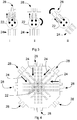
- Figure 1 shows the arrangement of a typical proton CT system.
- a beam of protons 10 passes through one or more position-sensitive detectors 12 and from there to impinge upon an object or patient 14 to be imaged. If the energy of the protons is high enough, they will most likely pass through the object or patient 14 and emerge from the far side of the patient with some residual energy, E R .
- the protons then pass through one or more position-sensitive detectors 16.
- the residual energy E R of the protons is then measured by an energy-sensitive detector 18.
- Data is collected from the detectors 12, 16, 18 and analysed by an associated computer system 20.
- the positions of individual protons as well as their residual energy, E R are recorded for a unique relative position of the patient relative to the system.
- Either the patient or the instrument is rotated by a small scan angle, typically 1° - 2°, about a central y-axis. The process is repeated over many scan angles.
- the line L can be represented by the parameters r and ⁇ , where ⁇ measures the angle of the line from the vertical, and r measures the distance of the line from the origin of the ( x , y ) plane.
- the above formula is used to define a transform which maps a function f ( x , y ) to a function p ( r , ⁇ ), where p ( r , ⁇ ) is the line integral of f ( x , y ) over the line defined by rand ⁇ .
- This transform is known as the Radon transform and denoted by R.
- the basic challenge of tomography is to reconstruct an image from its Radon transform. Fortunately, the Radon transform, when properly defined, has a well-defined inverse. In order to invert the transform, projection data spanning 180° is needed.
- FIG. 4 An arrangement that uses a finite number of (in this case, 8) sets of individual projection data from different scan angles then is as shown in Figure 4 .
- the individual projection images 28 are shown projected back through the image to obtain an estimate of the internal structures of the original object 22.
- the individual projections will interact constructively in regions that correspond to features in the original object 22.
- FBP Frtered Back-Projection
- BPF Back-Projection Filtered
- the embodiment of this invention implements a BPF using an analytic technique in to solve the reconstruction problem of going from the Radon transform of an object (that is the measurements) to the reconstructed object (that is the 2-dimensional image slice) only using each element of the data only once.
- the projections can be expressed as the Radon transform of the object that is to be reconstructed.
- This approach for reconstructing the image is to take the inverse Radon transform of the projections. This involves two steps: the image is back-projected and then filtered with a 2-dimensional filter.
- This operator represents the accumulation of the projections that pass through a point (x, y).
- the appropriate property is the proton relative stopping power.
- This line integral is a ray projection through a slice of an object being imaged, and is related to the path length in a reference material, typically the water-equivalent path length (WEPL).
- WEPL water-equivalent path length
- x cos ⁇ + y sin ⁇ t
- This convolution relation can be expressed as a filtering operation in 2-dimensional Fourier space.
- ⁇ x y FT ⁇ 1 FT b
- FT r ⁇ 1 IFT FT b ⁇
- a discrete formulation for the back-projected image, b needs to be used.
- the 2-dimensional matrix for b can be calculated from a set of acquired measurements in several ways. One possible scheme will now be described.
- This version relaxes the requirement for linear in-plane paths.
- the relationship between the convolution kernel and filter involves a 2-dimensional Fourier transform (in contrast with the FBP procedure, which involves a 1-dimensional Fourier transform).
- the finite size of the back-projection matrix and kernel must be considered in order to find the appropriate filter in the discrete Fourier space.
- the filtering operation is performed by multiplying the DFT of the back-projection matrix, b ( i , j ) by the DFT of k(i, j).
- the first summation is the sum of all the pixel values in the reconstructed image slice( ⁇ f ).
- the second sum is a summation over all pixels outside the back-projection region( ⁇ b ).
- the main elements of the proton CT system embodying the invention are shown in Figure 7 .
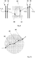
- the input vector, for an individual proton with initial energy E l , to the BPF algorithm consist of four sets of positional data obtained from the sets of detectors 30..36 ⁇ ( x 1 , y 2 ), ... , ( x 4 , y 4 ) ⁇ and the residual energy of the proton, E R , as recorded by an energy-sensitive detector 18 in Figure 1 .
- the path of the proton shown in Figure 7 is a diagrammatic example only.
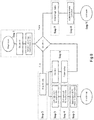
- Step 1 the number of rotations, N, is set and the Count initialised to zero.
- the values of the CT image matrix are also set to zero.
- Step 2 data is acquired from the instrument (at the initial scan angle).
- This individual projection data consists of the recorded vector for each identified individual proton path and its residual energy, ER, that is: x 1 , y 1 x 2 , y 2 x 3 , y 3 x 4 , y 4 E R
- Step 3 Proton energies are converted in Step 3 into water-equivalent path lengths ( WEPL ), to preserve the uniform dimensionality of all parameters.
- WEPL R R H 2 O E I ⁇ R H 2 O E R
- R H 2 O (100) is the range in water of a 100 MeV proton
- E l is the initial energy of the proton.
- WEPL R ⁇ ⁇ E I E R SP H 2 O e ⁇ 1 de , where SP H 2 O is the stopping power for protons in water.
- WEPL R ⁇ E I E R , where f ( E I , R ) returns the most probable value for WEPL , given the initial energy E l and estimate residual range, E R , from the energy-sensitive detector.
- the function f ( E I , R ) can be calculated from Monte Carlo simulations or from calibration experiments.
- the vector is now: x 1 , y 1 x 2 , y 2 x 3 , y 3 x 4 , y 4 WEPL R .
- Step 4 is to estimate the path of each proton through the patient 22. As illustrated in Figure 9 , this is done by projecting forward and backward from the respective (x, y) locations of the appropriate detectors 30..36 to determine the entry and exit voxels 40, 42 for the reconstruction. Protons experience multiple Coulomb scattering (MCS), so superior final image quality can be achieved if this is taken into account instead of assuming a straight-line path.
- MCS Coulomb scattering
- Any of the above methods, or another, can be used to estimate the most likely path of an individual proton through reconstruction matrix.
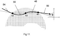
- a smooth (non-linear) path 46 or a piecewise linear representation 48 of the actual path 50 can be used (illustrated in Figure 10 ) in respect to any of the above methods.
- an n-knot spline may be employed to model the proton path 50, the inside the object.
- n knot points K1, K2, K3 are equally spaced between phantom entry and exit points 54, 56.
- back-projection is assumed linear between any two knot points, as shown in Figure 11 .
- the protons are projected back from the surface with trajectories parallel to the beam axis (at an angle ⁇ in the x-y plane). This prevents the back-projection rays "spreading-out" as they diverge from the object. Back-projecting away from the object into empty space along the actual entry and exit trajectories can result in a small quantitative error in the reconstructed stopping powers of up to 1%.
- Step 5 the associated WEPL R values are back-projected into the image matrix.
- the relevant formulation is Eqn. (5).
- step 7 the filtering operation given by Eqn. (8) is performed on the completed back-propagation matrix, b(x, y).
- step 8 the Finite Matrix Correction factor, C, (Eqn. 10) is calculated and applied in accordance with Eqn. (11).
- step 9 the proton CT image can be displayed.
Landscapes
- Health & Medical Sciences (AREA)
- Engineering & Computer Science (AREA)
- Life Sciences & Earth Sciences (AREA)
- Medical Informatics (AREA)
- Physics & Mathematics (AREA)
- General Health & Medical Sciences (AREA)
- Radiology & Medical Imaging (AREA)
- Nuclear Medicine, Radiotherapy & Molecular Imaging (AREA)
- Pathology (AREA)
- Veterinary Medicine (AREA)
- Biomedical Technology (AREA)
- Public Health (AREA)
- Animal Behavior & Ethology (AREA)
- Theoretical Computer Science (AREA)
- Heart & Thoracic Surgery (AREA)
- High Energy & Nuclear Physics (AREA)
- Molecular Biology (AREA)
- Surgery (AREA)
- Biophysics (AREA)
- Optics & Photonics (AREA)
- General Physics & Mathematics (AREA)
- Pulmonology (AREA)
- Computer Vision & Pattern Recognition (AREA)
- Analytical Chemistry (AREA)
- Biochemistry (AREA)
- Immunology (AREA)
- Chemical & Material Sciences (AREA)
- Quality & Reliability (AREA)
- Image Processing (AREA)
- Apparatus For Radiation Diagnosis (AREA)
- Analysing Materials By The Use Of Radiation (AREA)
Claims (15)
- Verfahren zur dreidimensionalen Bildrekonstruktion für Hadronen- und Ionenstrahlen in der Computertomographie, umfassend:a. ein Erzeugen einer Bildrekonstruktionsmatrix durch:
aus einer Vielzahl von Scanwinkeln, die ein abzubildendes Objekt (22) umgeben:i. Richten einer Vielzahl von Partikeln (24), so dass sie ein Objekt durchqueren; undii. Messen einer Bahn und Energie jedes Partikels, bevor und nachdem jeder Partikel das Objekt durchquert hat;iii. Berechnen einer äquivalenten Pfadlänge (Equivalent Path Length, EPL) für jeden Partikel innerhalb des Objekts;iv. Berechnen einer Eintrittsposition (40), an der jeder Artikel in das Objekt eingetreten ist, und einer Austrittsposition (42), an der jeder Partikel aus dem Objekt ausgetreten ist; undv. Addieren der EPL zu den Eintritts- und Austrittspositionen jedes Partikels der Bildrekonstruktionsmatrix oder einer Untergruppe von Elementen davon;b. Anwenden einer räumlich variierenden zweidimensionalen Filterfunktion auf die Bildrekonstruktionsmatrix, um eine gefilterte Rekonstruktionsmatrix zu generieren; undc. Anwenden eines Korrekturfaktors auf die gefilterte Rekonstruktionsmatrix, um die endliche Ausdehnung der Matrix mindestens teilweise zu korrigieren. - Verfahren zur Bildrekonstruktion nach Anspruch 1, wobei die Partikel Protonen, andere Hadronen oder Ionen sind.
- Verfahren zur Bildrekonstruktion nach Anspruch 1 oder Anspruch 2, wobei die EPL eine wasseräquivalente Pfadlänge ist.
- Verfahren zur Bildrekonstruktion nach einem der vorangehenden Ansprüche, wobei die Bahnen einzelner Partikel vor dem Durchqueren des Objekts durch eine Vielzahl von positionsempfindlichen Detektoren aufgezeichnet werden, auf die die Partikel treffen, bevor sie auf das Objekt treffen.
- Verfahren zur Bildrekonstruktion nach einem der vorangehenden Ansprüche, wobei die Bahnen einzelner Partikel nach dem Durchqueren des Objekts durch eine Vielzahl von positionsempfindlichen Detektoren aufgezeichnet werden, auf die die Partikel treffen, nachdem sie auf das Objekt treffen.
- Verfahren zur Bildrekonstruktion nach einem der vorangehenden Ansprüche, wobei jede gemessene Partikelbahn zurückverfolgt wird, um die Bildrekonstruktionsmatrix zu erzeugen, und an jeder Position innerhalb dieser Bildrekonstruktionsmatrix entsprechende Werte des folgenden Integrals platziert werden:

- Verfahren zur Bildrekonstruktion nach Anspruch 6, wobei das Erzeugen der Bildrekonstruktionsmatrix abgeschlossen ist, bevor eine Filterung auf ihre Inhalte angewendet wird.
- Verfahren zur Bildrekonstruktion nach einem der vorangehenden Ansprüche, wobei die Bildrekonstruktionsmatrix einem bandbegrenztem Faltungskern unterliegt, bei dem die Matrix einem Sampling-Pitch auf dem Faltungskern im Frequenzbereich unterzogen wird.
- Verfahren zur Bildrekonstruktion nach Anspruch 8, wobei ein zusätzlicher Glättungsfilter durch Sampling einer geeigneten Funktion im Frequenzbereich und Multiplizieren des Faltungskerns angewendet wird.
- Verfahren zur Bildrekonstruktion nach Anspruch 9, wobei der zusätzliche Glättungsfilter ein Shepp-Logan- oder ein Gaußscher Filter ist.
- Verfahren zur Bildrekonstruktion nach einem der vorangehenden Ansprüche, wobei eine rückprojizierte Matrix gegeben ist durch:

- Verfahren nach Anspruch 11, wobei die die zweidimensionale Filterfunktion die folgende Form aufweist:

- Verfahren nach einem der vorangehenden Ansprüche, wobei der Korrekturfaktor

- Verfahren zur Bildrekonstruktion nach einem der vorangehenden Ansprüche, wobei ein weiterer Korrekturfaktor angewendet wird, um Restfehler in der gefilterten Rekonstruktionsmatrix weiter zu reduzieren, um Kräfte zu stoppen, die aus Bahnen von aus dem Objekt austretenden Partikeln entstehen, die zu einer Kollimierungsachse des auftreffenden Partikelstrahls nicht parallel sind.
- Computertomographievorrichtung, umfassend eine Partikelquelle, erste Detektionsmittel zum Detektieren der Position und Energie von Partikeln vor ihrem Durchqueren eines Objekts, zweite Detektionsmittel zum Detektieren der Position und Energie von Partikeln vor ihrem Durchqueren eines Objekts, und Analysemittel, die konfiguriert sind, um ein Bild des Objekts durch Analyse des Ausgangs der Detektionsmittel mithilfe des Verfahrens nach einem der vorangehenden Ansprüche zu rekonstruieren.
Applications Claiming Priority (2)
| Application Number | Priority Date | Filing Date | Title |
|---|---|---|---|
| GBGB1413729.3A GB201413729D0 (en) | 2014-08-01 | 2014-08-01 | Method and apparatus for proton computed tomography |
| PCT/GB2015/052208 WO2016016653A1 (en) | 2014-08-01 | 2015-07-30 | Method and apparatus for proton computerised tomography |
Publications (2)
| Publication Number | Publication Date |
|---|---|
| EP3174465A1 EP3174465A1 (de) | 2017-06-07 |
| EP3174465B1 true EP3174465B1 (de) | 2021-10-20 |
Family
ID=51587652
Family Applications (1)
| Application Number | Title | Priority Date | Filing Date |
|---|---|---|---|
| EP15747199.6A Active EP3174465B1 (de) | 2014-08-01 | 2015-07-30 | Verfahren und vorrichtung zur protonencomputertomographie |
Country Status (4)
| Country | Link |
|---|---|
| US (1) | US10249063B2 (de) |
| EP (1) | EP3174465B1 (de) |
| GB (2) | GB201413729D0 (de) |
| WO (1) | WO2016016653A1 (de) |
Families Citing this family (11)
| Publication number | Priority date | Publication date | Assignee | Title |
|---|---|---|---|---|
| AU2017203109B2 (en) * | 2016-05-11 | 2018-12-06 | ProTom International Holding Corp. | Cancer treatment room fiducial marker apparatus and method of use thereof |
| US11141608B2 (en) | 2017-04-07 | 2021-10-12 | Massachusetts Institute Of Technology | Compact proton beam energy modulator |
| CN107497059A (zh) * | 2017-07-12 | 2017-12-22 | 合肥中科离子医学技术装备有限公司 | 一种质子ct精准控制方法 |
| CN111836583B (zh) * | 2017-12-28 | 2022-03-29 | 北伊利诺伊大学董事会 | 处理管道以用于立即进行粒子图像重建 |
| JP7273272B2 (ja) * | 2018-05-28 | 2023-05-15 | 国立研究開発法人理化学研究所 | 角度オフセットによる断層画像データの取得方法、取得装置、および制御プログラム |
| US10690787B2 (en) * | 2018-07-16 | 2020-06-23 | Vieworks Co., Ltd. | Radiation imaging system |
| US11614552B2 (en) | 2019-04-18 | 2023-03-28 | Decision Sciences International Corporation | Charged particle scanners |
| WO2020246788A1 (ko) * | 2019-06-05 | 2020-12-10 | 세종대학교산학협력단 | 스캐닝 홀로그램 기반 자동광학검사 장치 및 방법 |
| JP7264751B2 (ja) * | 2019-07-08 | 2023-04-25 | 株式会社ニューフレアテクノロジー | 検査装置及び検査方法 |
| CN112569478B (zh) * | 2019-09-29 | 2023-05-16 | 王宏凯 | 一种同步读出数字型质子ct成像的方法及装置 |
| GB202311277D0 (en) * | 2023-07-21 | 2023-09-06 | Univ Of Lincoln | Aparatus for determing energy of hadron patricles |
Family Cites Families (11)
| Publication number | Priority date | Publication date | Assignee | Title |
|---|---|---|---|---|
| JPS6340381A (ja) | 1986-08-06 | 1988-02-20 | Toshiba Corp | 放射線検出器 |
| FR2652655A1 (fr) | 1989-10-04 | 1991-04-05 | Commissariat Energie Atomique | Dispositif matriciel de grandes dimensions pour la prise ou la restitution d'images. |
| GB2359187A (en) | 2000-02-11 | 2001-08-15 | Kindbrisk Ltd | Device and method for two-dimensional detection of particles or electromagnetic radiation |
| DE10244176A1 (de) | 2002-09-23 | 2004-04-08 | Siemens Ag | Bilddetektor für Röntgenstrahlung |
| DE102009035231B4 (de) | 2009-07-29 | 2013-08-08 | Gsi Helmholtzzentrum Für Schwerionenforschung Gmbh | Phantom zur experimentellen in-vitro-Validierung von Bestrahlungen unter Bewegungseinfluss unter Berücksichtigung der biologisch effektiven Dosis |
| EP2534471A4 (de) | 2010-02-12 | 2015-03-18 | Univ Loma Linda Med | Systeme und methodologien für protonen-computertomografie |
| JP2013527918A (ja) | 2010-04-02 | 2013-07-04 | ボード オブ トラスティーズ オブ ノーザン イリノイ ユニバーシティー | 3次元陽子コンピュータ断層撮影のための高性能計算(hpc−pct) |
| US20120292517A1 (en) | 2011-05-19 | 2012-11-22 | Washington University | Real-time imaging dosimeter systems and method |
| WO2013116709A1 (en) * | 2012-02-01 | 2013-08-08 | The Research Foundation of States University of New York | Computerized image reconstruction method and apparatus |
| JP5791546B2 (ja) | 2012-02-29 | 2015-10-07 | 株式会社日立製作所 | 放射線計測装置の較正方法及び粒子線治療装置 |
| JP6452733B2 (ja) * | 2014-06-16 | 2019-01-16 | ロマ リンダ ユニバーシティ | 高エネルギー電子ビームによるラジオグラフィおよびコンピュータ断層撮影 |
-
2014
- 2014-08-01 GB GBGB1413729.3A patent/GB201413729D0/en not_active Ceased
-
2015
- 2015-07-30 EP EP15747199.6A patent/EP3174465B1/de active Active
- 2015-07-30 US US15/500,371 patent/US10249063B2/en active Active
- 2015-07-30 WO PCT/GB2015/052208 patent/WO2016016653A1/en not_active Ceased
- 2015-07-30 GB GB1701973.8A patent/GB2543695B/en active Active
Also Published As
| Publication number | Publication date |
|---|---|
| US20170221230A1 (en) | 2017-08-03 |
| WO2016016653A1 (en) | 2016-02-04 |
| GB2543695B (en) | 2020-11-25 |
| EP3174465A1 (de) | 2017-06-07 |
| GB201413729D0 (en) | 2014-09-17 |
| GB2543695A (en) | 2017-04-26 |
| US10249063B2 (en) | 2019-04-02 |
| GB201701973D0 (en) | 2017-03-22 |
Similar Documents
| Publication | Publication Date | Title |
|---|---|---|
| US10249063B2 (en) | Method and apparatus for proton computerised tomography | |
| Zygmanski et al. | The measurement of proton stopping power using proton-cone-beam computed tomography | |
| US7418073B2 (en) | Computed tomography device and method with three-dimensional backprojection | |
| Thibault et al. | A three‐dimensional statistical approach to improved image quality for multislice helical CT | |
| Zhou et al. | A computer simulation platform for the optimization of a breast tomosynthesis system | |
| Rit et al. | Filtered backprojection proton CT reconstruction along most likely paths | |
| Yan et al. | Towards the clinical implementation of iterative low‐dose cone‐beam CT reconstruction in image‐guided radiation therapy: Cone/ring artifact correction and multiple GPU implementation | |
| Fahimian et al. | Radiation dose reduction in medical x‐ray CT via Fourier‐based iterative reconstruction | |
| CN103384498A (zh) | 探测装置 | |
| CN105326519B (zh) | X射线图像形成、散射成分计算以及重建的方法及装置 | |
| Geva et al. | X-ray computed tomography through scatter | |
| Rambo Sølie et al. | Image quality of list-mode proton imaging without front trackers | |
| US8335358B2 (en) | Method and system for reconstructing a medical image of an object | |
| Krah et al. | Scattering proton CT | |
| Saha | Single photon emission computed tomography | |
| US7737972B2 (en) | Systems and methods for digital volumetric laminar tomography | |
| US9545231B2 (en) | Optimized aperture selection imaging computed tomography system and method | |
| Chen et al. | SparseCT: System concept and design of multislit collimators | |
| Lee et al. | Mutual information-based non-local total variation denoiser for low-dose cone-beam computed tomography | |
| Jacobson et al. | Abbreviated on-treatment CBCT using roughness penalized mono-energization of kV-MV data and a multi-layer MV imager | |
| CN117561545A (zh) | 锚定内核散射估计 | |
| Lohvithee | Iterative reconstruction technique for cone-beam computed tomography with limited data | |
| CN111685786B (zh) | X射线ct装置、图像重建设备及图像重建方法 | |
| GLGGGGG et al. | This invention relates to a method and apparatus for 3-dimensional image reconstruction in computerised tomography. More specifically, it relates to computerised tomographic image reconstruction and typically in image reconstruction for applications in hadron (eg, proton) and ion beam therapy. | |
| Cai | Artefact Reduction Methods for Iterative Reconstruction in Full-fan Cone Beam CT Radiotherapy Applications |
Legal Events
| Date | Code | Title | Description |
|---|---|---|---|
| STAA | Information on the status of an ep patent application or granted ep patent |
Free format text: STATUS: THE INTERNATIONAL PUBLICATION HAS BEEN MADE |
|
| 17P | Request for examination filed |
Effective date: 20170207 |
|
| AK | Designated contracting states |
Kind code of ref document: A1 Designated state(s): AL AT BE BG CH CY CZ DE DK EE ES FI FR GB GR HR HU IE IS IT LI LT LU LV MC MK MT NL NO PL PT RO RS SE SI SK SM TR |
|
| AX | Request for extension of the european patent |
Extension state: BA ME |
|
| PUAI | Public reference made under article 153(3) epc to a published international application that has entered the european phase |
Free format text: ORIGINAL CODE: 0009012 |
|
| STAA | Information on the status of an ep patent application or granted ep patent |
Free format text: STATUS: REQUEST FOR EXAMINATION WAS MADE |
|
| DAV | Request for validation of the european patent (deleted) | ||
| DAX | Request for extension of the european patent (deleted) | ||
| GRAP | Despatch of communication of intention to grant a patent |
Free format text: ORIGINAL CODE: EPIDOSNIGR1 |
|
| STAA | Information on the status of an ep patent application or granted ep patent |
Free format text: STATUS: GRANT OF PATENT IS INTENDED |
|
| INTG | Intention to grant announced |
Effective date: 20210510 |
|
| GRAS | Grant fee paid |
Free format text: ORIGINAL CODE: EPIDOSNIGR3 |
|
| GRAA | (expected) grant |
Free format text: ORIGINAL CODE: 0009210 |
|
| STAA | Information on the status of an ep patent application or granted ep patent |
Free format text: STATUS: THE PATENT HAS BEEN GRANTED |
|
| AK | Designated contracting states |
Kind code of ref document: B1 Designated state(s): AL AT BE BG CH CY CZ DE DK EE ES FI FR GR HR HU IE IS IT LI LT LU LV MC MK MT NL NO PL PT RO RS SE SI SK SM TR |
|
| RBV | Designated contracting states (corrected) |
Designated state(s): AL AT BE BG CH CY CZ DE DK EE ES FI FR GR HR HU IE IS IT LI LT LU LV MC MK MT NL NO PL PT RO RS SE SI SK SM TR |
|
| REG | Reference to a national code |
Ref country code: CH Ref legal event code: EP |
|
| REG | Reference to a national code |
Ref country code: DE Ref legal event code: R096 Ref document number: 602015074268 Country of ref document: DE |
|
| REG | Reference to a national code |
Ref country code: IE Ref legal event code: FG4D |
|
| REG | Reference to a national code |
Ref country code: AT Ref legal event code: REF Ref document number: 1439248 Country of ref document: AT Kind code of ref document: T Effective date: 20211115 |
|
| REG | Reference to a national code |
Ref country code: LT Ref legal event code: MG9D |
|
| REG | Reference to a national code |
Ref country code: NL Ref legal event code: MP Effective date: 20211020 |
|
| REG | Reference to a national code |
Ref country code: AT Ref legal event code: MK05 Ref document number: 1439248 Country of ref document: AT Kind code of ref document: T Effective date: 20211020 |
|
| PG25 | Lapsed in a contracting state [announced via postgrant information from national office to epo] |
Ref country code: RS Free format text: LAPSE BECAUSE OF FAILURE TO SUBMIT A TRANSLATION OF THE DESCRIPTION OR TO PAY THE FEE WITHIN THE PRESCRIBED TIME-LIMIT Effective date: 20211020 Ref country code: LT Free format text: LAPSE BECAUSE OF FAILURE TO SUBMIT A TRANSLATION OF THE DESCRIPTION OR TO PAY THE FEE WITHIN THE PRESCRIBED TIME-LIMIT Effective date: 20211020 Ref country code: FI Free format text: LAPSE BECAUSE OF FAILURE TO SUBMIT A TRANSLATION OF THE DESCRIPTION OR TO PAY THE FEE WITHIN THE PRESCRIBED TIME-LIMIT Effective date: 20211020 Ref country code: BG Free format text: LAPSE BECAUSE OF FAILURE TO SUBMIT A TRANSLATION OF THE DESCRIPTION OR TO PAY THE FEE WITHIN THE PRESCRIBED TIME-LIMIT Effective date: 20220120 Ref country code: AT Free format text: LAPSE BECAUSE OF FAILURE TO SUBMIT A TRANSLATION OF THE DESCRIPTION OR TO PAY THE FEE WITHIN THE PRESCRIBED TIME-LIMIT Effective date: 20211020 |
|
| PG25 | Lapsed in a contracting state [announced via postgrant information from national office to epo] |
Ref country code: IS Free format text: LAPSE BECAUSE OF FAILURE TO SUBMIT A TRANSLATION OF THE DESCRIPTION OR TO PAY THE FEE WITHIN THE PRESCRIBED TIME-LIMIT Effective date: 20220220 Ref country code: SE Free format text: LAPSE BECAUSE OF FAILURE TO SUBMIT A TRANSLATION OF THE DESCRIPTION OR TO PAY THE FEE WITHIN THE PRESCRIBED TIME-LIMIT Effective date: 20211020 Ref country code: PT Free format text: LAPSE BECAUSE OF FAILURE TO SUBMIT A TRANSLATION OF THE DESCRIPTION OR TO PAY THE FEE WITHIN THE PRESCRIBED TIME-LIMIT Effective date: 20220221 Ref country code: PL Free format text: LAPSE BECAUSE OF FAILURE TO SUBMIT A TRANSLATION OF THE DESCRIPTION OR TO PAY THE FEE WITHIN THE PRESCRIBED TIME-LIMIT Effective date: 20211020 Ref country code: NO Free format text: LAPSE BECAUSE OF FAILURE TO SUBMIT A TRANSLATION OF THE DESCRIPTION OR TO PAY THE FEE WITHIN THE PRESCRIBED TIME-LIMIT Effective date: 20220120 Ref country code: NL Free format text: LAPSE BECAUSE OF FAILURE TO SUBMIT A TRANSLATION OF THE DESCRIPTION OR TO PAY THE FEE WITHIN THE PRESCRIBED TIME-LIMIT Effective date: 20211020 Ref country code: LV Free format text: LAPSE BECAUSE OF FAILURE TO SUBMIT A TRANSLATION OF THE DESCRIPTION OR TO PAY THE FEE WITHIN THE PRESCRIBED TIME-LIMIT Effective date: 20211020 Ref country code: HR Free format text: LAPSE BECAUSE OF FAILURE TO SUBMIT A TRANSLATION OF THE DESCRIPTION OR TO PAY THE FEE WITHIN THE PRESCRIBED TIME-LIMIT Effective date: 20211020 Ref country code: GR Free format text: LAPSE BECAUSE OF FAILURE TO SUBMIT A TRANSLATION OF THE DESCRIPTION OR TO PAY THE FEE WITHIN THE PRESCRIBED TIME-LIMIT Effective date: 20220121 Ref country code: ES Free format text: LAPSE BECAUSE OF FAILURE TO SUBMIT A TRANSLATION OF THE DESCRIPTION OR TO PAY THE FEE WITHIN THE PRESCRIBED TIME-LIMIT Effective date: 20211020 |
|
| REG | Reference to a national code |
Ref country code: DE Ref legal event code: R097 Ref document number: 602015074268 Country of ref document: DE |
|
| PG25 | Lapsed in a contracting state [announced via postgrant information from national office to epo] |
Ref country code: SM Free format text: LAPSE BECAUSE OF FAILURE TO SUBMIT A TRANSLATION OF THE DESCRIPTION OR TO PAY THE FEE WITHIN THE PRESCRIBED TIME-LIMIT Effective date: 20211020 Ref country code: SK Free format text: LAPSE BECAUSE OF FAILURE TO SUBMIT A TRANSLATION OF THE DESCRIPTION OR TO PAY THE FEE WITHIN THE PRESCRIBED TIME-LIMIT Effective date: 20211020 Ref country code: RO Free format text: LAPSE BECAUSE OF FAILURE TO SUBMIT A TRANSLATION OF THE DESCRIPTION OR TO PAY THE FEE WITHIN THE PRESCRIBED TIME-LIMIT Effective date: 20211020 Ref country code: EE Free format text: LAPSE BECAUSE OF FAILURE TO SUBMIT A TRANSLATION OF THE DESCRIPTION OR TO PAY THE FEE WITHIN THE PRESCRIBED TIME-LIMIT Effective date: 20211020 Ref country code: DK Free format text: LAPSE BECAUSE OF FAILURE TO SUBMIT A TRANSLATION OF THE DESCRIPTION OR TO PAY THE FEE WITHIN THE PRESCRIBED TIME-LIMIT Effective date: 20211020 Ref country code: CZ Free format text: LAPSE BECAUSE OF FAILURE TO SUBMIT A TRANSLATION OF THE DESCRIPTION OR TO PAY THE FEE WITHIN THE PRESCRIBED TIME-LIMIT Effective date: 20211020 |
|
| PLBE | No opposition filed within time limit |
Free format text: ORIGINAL CODE: 0009261 |
|
| STAA | Information on the status of an ep patent application or granted ep patent |
Free format text: STATUS: NO OPPOSITION FILED WITHIN TIME LIMIT |
|
| 26N | No opposition filed |
Effective date: 20220721 |
|
| PG25 | Lapsed in a contracting state [announced via postgrant information from national office to epo] |
Ref country code: AL Free format text: LAPSE BECAUSE OF FAILURE TO SUBMIT A TRANSLATION OF THE DESCRIPTION OR TO PAY THE FEE WITHIN THE PRESCRIBED TIME-LIMIT Effective date: 20211020 |
|
| PG25 | Lapsed in a contracting state [announced via postgrant information from national office to epo] |
Ref country code: SI Free format text: LAPSE BECAUSE OF FAILURE TO SUBMIT A TRANSLATION OF THE DESCRIPTION OR TO PAY THE FEE WITHIN THE PRESCRIBED TIME-LIMIT Effective date: 20211020 |
|
| PG25 | Lapsed in a contracting state [announced via postgrant information from national office to epo] |
Ref country code: MC Free format text: LAPSE BECAUSE OF FAILURE TO SUBMIT A TRANSLATION OF THE DESCRIPTION OR TO PAY THE FEE WITHIN THE PRESCRIBED TIME-LIMIT Effective date: 20211020 |
|
| REG | Reference to a national code |
Ref country code: CH Ref legal event code: PL |
|
| REG | Reference to a national code |
Ref country code: BE Ref legal event code: MM Effective date: 20220731 |
|
| PG25 | Lapsed in a contracting state [announced via postgrant information from national office to epo] |
Ref country code: LU Free format text: LAPSE BECAUSE OF NON-PAYMENT OF DUE FEES Effective date: 20220730 Ref country code: LI Free format text: LAPSE BECAUSE OF NON-PAYMENT OF DUE FEES Effective date: 20220731 Ref country code: CH Free format text: LAPSE BECAUSE OF NON-PAYMENT OF DUE FEES Effective date: 20220731 |
|
| PG25 | Lapsed in a contracting state [announced via postgrant information from national office to epo] |
Ref country code: IT Free format text: LAPSE BECAUSE OF FAILURE TO SUBMIT A TRANSLATION OF THE DESCRIPTION OR TO PAY THE FEE WITHIN THE PRESCRIBED TIME-LIMIT Effective date: 20211020 Ref country code: BE Free format text: LAPSE BECAUSE OF NON-PAYMENT OF DUE FEES Effective date: 20220731 |
|
| P01 | Opt-out of the competence of the unified patent court (upc) registered |
Effective date: 20230517 |
|
| PG25 | Lapsed in a contracting state [announced via postgrant information from national office to epo] |
Ref country code: IE Free format text: LAPSE BECAUSE OF NON-PAYMENT OF DUE FEES Effective date: 20220730 |
|
| PG25 | Lapsed in a contracting state [announced via postgrant information from national office to epo] |
Ref country code: HU Free format text: LAPSE BECAUSE OF FAILURE TO SUBMIT A TRANSLATION OF THE DESCRIPTION OR TO PAY THE FEE WITHIN THE PRESCRIBED TIME-LIMIT; INVALID AB INITIO Effective date: 20150730 |
|
| PG25 | Lapsed in a contracting state [announced via postgrant information from national office to epo] |
Ref country code: MK Free format text: LAPSE BECAUSE OF FAILURE TO SUBMIT A TRANSLATION OF THE DESCRIPTION OR TO PAY THE FEE WITHIN THE PRESCRIBED TIME-LIMIT Effective date: 20211020 Ref country code: CY Free format text: LAPSE BECAUSE OF FAILURE TO SUBMIT A TRANSLATION OF THE DESCRIPTION OR TO PAY THE FEE WITHIN THE PRESCRIBED TIME-LIMIT Effective date: 20211020 |
|
| PG25 | Lapsed in a contracting state [announced via postgrant information from national office to epo] |
Ref country code: TR Free format text: LAPSE BECAUSE OF FAILURE TO SUBMIT A TRANSLATION OF THE DESCRIPTION OR TO PAY THE FEE WITHIN THE PRESCRIBED TIME-LIMIT Effective date: 20211020 |
|
| PG25 | Lapsed in a contracting state [announced via postgrant information from national office to epo] |
Ref country code: MT Free format text: LAPSE BECAUSE OF FAILURE TO SUBMIT A TRANSLATION OF THE DESCRIPTION OR TO PAY THE FEE WITHIN THE PRESCRIBED TIME-LIMIT Effective date: 20211020 |
|
| PGFP | Annual fee paid to national office [announced via postgrant information from national office to epo] |
Ref country code: DE Payment date: 20250722 Year of fee payment: 11 |
|
| PGFP | Annual fee paid to national office [announced via postgrant information from national office to epo] |
Ref country code: FR Payment date: 20250725 Year of fee payment: 11 |