EP3173601A1 - Clapet de non-retour pour une bielle pour une compression variable d'un moteur à combustion interne et bielle comprenant un tel clapet de non-retour - Google Patents
Clapet de non-retour pour une bielle pour une compression variable d'un moteur à combustion interne et bielle comprenant un tel clapet de non-retour Download PDFInfo
- Publication number
- EP3173601A1 EP3173601A1 EP16199578.2A EP16199578A EP3173601A1 EP 3173601 A1 EP3173601 A1 EP 3173601A1 EP 16199578 A EP16199578 A EP 16199578A EP 3173601 A1 EP3173601 A1 EP 3173601A1
- Authority
- EP
- European Patent Office
- Prior art keywords
- valve
- closing body
- valve closing
- check valve
- connecting rod
- Prior art date
- Legal status (The legal status is an assumption and is not a legal conclusion. Google has not performed a legal analysis and makes no representation as to the accuracy of the status listed.)
- Granted
Links
Images

Classifications
-
- F—MECHANICAL ENGINEERING; LIGHTING; HEATING; WEAPONS; BLASTING
- F02—COMBUSTION ENGINES; HOT-GAS OR COMBUSTION-PRODUCT ENGINE PLANTS
- F02B—INTERNAL-COMBUSTION PISTON ENGINES; COMBUSTION ENGINES IN GENERAL
- F02B75/00—Other engines
- F02B75/04—Engines with variable distances between pistons at top dead-centre positions and cylinder heads
- F02B75/045—Engines with variable distances between pistons at top dead-centre positions and cylinder heads by means of a variable connecting rod length
-
- F—MECHANICAL ENGINEERING; LIGHTING; HEATING; WEAPONS; BLASTING
- F16—ENGINEERING ELEMENTS AND UNITS; GENERAL MEASURES FOR PRODUCING AND MAINTAINING EFFECTIVE FUNCTIONING OF MACHINES OR INSTALLATIONS; THERMAL INSULATION IN GENERAL
- F16K—VALVES; TAPS; COCKS; ACTUATING-FLOATS; DEVICES FOR VENTING OR AERATING
- F16K15/00—Check valves
- F16K15/02—Check valves with guided rigid valve members
- F16K15/025—Check valves with guided rigid valve members the valve being loaded by a spring
- F16K15/026—Check valves with guided rigid valve members the valve being loaded by a spring the valve member being a movable body around which the medium flows when the valve is open
Definitions
- the invention relates to a check valve for a connecting rod for a variable compression of an internal combustion engine with at least one hydraulic chamber, wherein the hydraulic chamber of the connecting rod is connectable by means of the check valve with a supply port or a tank, wherein the check valve a cup-shaped valve housing and along a valve longitudinal axis axially displaceable Valve-closing body which is biased by a valve spring against a valve seat, and a connecting rod with such a check valve.
- a high compression ratio has a positive effect on the efficiency of the internal combustion engine.
- compression ratio is generally understood the ratio of the entire cylinder space before compression to the remaining cylinder space after compression.
- the compression ratio may only be selected so high that a so-called "knocking" of the internal combustion engine is avoided during full load operation.
- the compression ratio could be selected with higher values, without any "knocking". would occur.
- the important part load range of an internal combustion engine can be improved if the compression ratio is variably adjustable.
- systems with variable connecting rod length are known, for example, which actuate an eccentric adjustment of a connecting rod with the aid of hydraulic changeover valves.
- Such a connecting rod is for example from the DE 10 2013 107 127 A1 and comprises an eccentric adjusting device for adjusting an effective connecting rod length, wherein the eccentric adjusting device has an eccentric cooperating with an eccentric, and two pistons which are guided displaceably in a hydraulic chamber and in which on the eccentric lever engaging eccentric rods of the eccentric adjusting device are stored.
- An adjustment of the eccentric adjusting device is adjustable by means of a switching valve. Changing the travel will change the effective connecting rod length. Thus, the compression of an internal combustion engine can be controlled.
- Check valves in the connecting rod each prevent a backflow of hydraulic fluid from the hydraulic chambers to a supply port or a tank.
- An object of the invention is to provide another improved check valve and further an improved connecting rod with a check valve.
- the invention is based on a check valve for a connecting rod for variable compression of an internal combustion engine having at least one hydraulic chamber, wherein the hydraulic chamber of the connecting rod is connectable by means of the check valve with a supply port or a tank, and wherein the check valve, a valve housing and along a valve longitudinal axis axially between an open and a closed position having displaceable valve closing body, which is biased by a valve spring against a valve seat.
- a mandrel-shaped guide body is provided, which projects through the valve spring and by means of which the valve spring is guided both in the open position and in the closed position of the valve closing body.
- the guide body advantageously extends at least from one end of the valve spring to the opposite end of the valve spring, i. in its entire length, both in the compressed and in the extended operating state of the valve spring.
- the construction of the check valve allows a stroke limitation of the valve closing body.
- the invention allows a guide of the valve spring over the entire length, so that no gap can arise in which the valve spring hineingeraten in transverse forces and thus tilt or can be destroyed.
- the reliability of the check valve is improved.
- the guide body may be guided in the valve closing body. If the valve spring is arranged on the valve closing body as a guide body, the valve closing body can be guided over its entire circumference. A tilting of the same is thus excluded.
- valve closing body is provided guided in the valve housing. This is the valve closing body a comparatively long guide path available, so that tilting or tilting of the valve closing body is excluded.
- the mandrel-shaped guide body is formed stationary with the valve housing and be provided submersible in the valve closing body.
- valve closing body when the valve closing body is designed as a valve closing piston, which is biased by the valve spring against a bottom of the valve housing as a valve seat, wherein the valve spring is guided by means guided in the valve closing piston guide body of the holding element.
- the valve housing may be cup-shaped. This allows a simple production of the valve housing.
- the valve housing may be a Einschraubgephaseuse that can be easily screwed into a connecting rod.
- the bottom of the valve housing may have an opening arranged axially relative to the valve longitudinal axis, which opening is assigned to the supply connection or to the tank and can be closed by means of the valve closing piston. This allows a simple production of the supply connection of the valve housing.
- one or more axial bores may be provided in the valve-closing piston in order to allow a flow of hydraulic fluid in the direction of the hydraulic chamber when opening the valve-closing body. Due to the axial bores in the valve closing piston can be dispensed with elaborate radial bores in the valve housing and the valve closing piston to be guided over its entire circumference.
- the valve closing body may have an interior, in which the guide body is provided guided and in which the guide body is immersed in opening the valve closing body. This allows a reliable actuation of the valve closing body and a secure guidance of the valve spring over its entire length.
- valve closing body may have one or more radial vent holes, which open into the axial bores.
- valve closing body can be vented to the guide body
- the mandrel-shaped guide body can be designed to be movable with the valve closing body and be provided so as to be submersible in the valve housing or a cover arranged in the valve housing.
- the valve closing body may comprise the mandrel-shaped guide body, by means of which the valve spring is guided, wherein the guide body in the valve housing or a cover arranged in the valve housing is feasible.
- the lid can be pressed into the valve housing.
- a closure element of the valve housing axially relative to the valve longitudinal axis Having arranged opening which is assigned to the supply port or the tank and closed by means of the valve closing body. This allows a simple construction of the check valve.
- the bottom of the valve housing may have an axially disposed relative to the longitudinal axis of the valve opening, which is associated with the supply port or the tank and closed by means of the valve closing body. This allows a simple construction of the check valve.
- one or more axial bores may be provided in the valve closing body in order to allow a flow of hydraulic fluid in the direction of the hydraulic chamber when opening the valve closing body.
- valve closing body may have one or more depressions in order to allow a flow of hydraulic fluid in the direction of the hydraulic chamber when opening the valve closing body.
- check valve As a material for the check valve can be used in the aforementioned embodiments advantageous steel, aluminum, aluminum alloy or plastic.
- a connecting rod is proposed for a variable compression of an internal combustion engine having at least one hydraulic chamber, wherein the hydraulic chamber is connectable by means of a check valve according to one or more of the features described above with a supply connection or a bearing shell or a tank of the connecting rod ,
- the check valves of the connecting rod may be identically constructed, or one of the check valves may be formed according to the first described embodiment and the other of the check valves according to the second embodiment
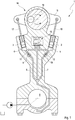
- FIG. 1 shows a schematic representation of an inventive connecting rod 1 for a variable compression of an internal combustion engine, with an eccentric adjusting device 14 for adjusting an effective connecting rod length.
- the eccentric adjusting device 14 has an eccentric 16 which interacts with a one-part or multi-part eccentric lever 15. In this case, an adjustment of the eccentric adjusting device 14 by means of a switching valve 13 is adjustable.
- a rotation of the adjustable eccentric adjusting device 14 is initiated by the action of mass and load forces of the internal combustion engine, which act on the eccentric adjusting device in a working cycle of the internal combustion engine.
- the rotary movement or adjusting movement is assisted by one or more of hydraulic fluid, in particular engine oil, acted upon in the connecting rod 1 integrated piston 2, 3, or prevent the pistons 2, 3 a return of the eccentric adjusting device 14 due to varying directions of force acting on the eccentric -Verstell Surprise 14 acting forces.
- the pistons 2, 3 are operatively connected by means of eccentric rods 17, 18 on both sides with the eccentric lever 15.
- the pistons 2, 3 are arranged displaceably in hydraulic chambers 4, 5 and are acted upon via hydraulic fluid lines 6, 7 from the bearing eye 8 with hydraulic fluid via check valves 9, 10, the structure of which will be explained in more detail below.
- check valves 9, 10 shown only schematically prevent backflow of the hydraulic fluid from the hydraulic chambers 4, 5 back into the hydraulic fluid conduits 6, 7 in a bearing shell of the Hublagerauges 8 and an unspecified tank and allow a Nachsaugen hydraulic fluid in the hydraulic chambers 4, 5th
- the hydraulic chambers 4, 5 are connected to further hydraulic fluid lines 11, 12 which cooperate with the switching valve.
- FIG. 2 shows a first embodiment of the first check valve 9 in longitudinal section, wherein the second check valve 10 may be constructed the same, so that only the check valve 9 is described below.
- the non-return valve 9 has a cup-shaped valve housing 19 and a valve closing body 20 axially displaceable along a valve longitudinal axis L, which is biased against a valve seat 23 by means of a valve spring 22 arranged between the valve closing body 20 and a holding element 21 fastened in the valve housing 19.
- the valve closing body 20 is designed as a valve closing piston, which is guided in the valve housing 19 and biased by the valve spring 22 against a bottom 24 of the valve housing 19 as a valve seat.
- the valve spring 22 is by means of a mandrel-shaped, guided in the valve closing piston 20 guide body 25 of the holding element 21 is provided.
- the mandrel-shaped guide body 25, which projects through the valve spring 22 in its entire length, is formed in this embodiment in a stationary manner with the valve housing 19 and provided immersible in the valve closing body 20.
- the guide body 25 dips with its free end into an interior space 26 of the valve closing piston 20.
- One or more radial vent holes 27 of the valve closing piston 20 allow an exchange of hydraulic fluid between the interior 26 and an interior 28 of the valve housing 19th
- the bottom 24 of the valve housing 19 has an opening 29 which is axially arranged with respect to the valve longitudinal axis L and which is assigned to the supply connection or the tank (not shown) and can be closed by means of the valve closing piston 20.
- valve closing piston 20 In the case of a resumption of hydraulic fluid, the valve closing piston 20 is opened against the spring force of the valve spring 22.
- the hydraulic fluid sucked in via the opening 29 can, via one or more axial bores 30 of the valve closing piston 20, move the interior of the valve housing 19 and axial openings 31 in the retaining element 21 in the direction of the hydraulic chamber 4 (FIG. FIG. 1 ) stream.
- FIG. 2 How out FIG. 2 can be seen open the vent holes 27 in the axial bores 30 of the valve closing piston 20.
- the vent holes 27 extend to an outside of the valve closing piston 20th
- the improved construction of the check valves 9, 10 according to the invention allows the valve spring 22 to be guided over the entire length, so that no intermediate space can arise in which the valve spring 22 can get stuck in transverse forces and thus be destroyed.
- valve closing body 20 is considered advantageous that can be dispensed with radial bores in the valve housing 19, as this is preferably provided screwed into the connecting rod 1. This is also advantageous that the valve closing body 20 can be performed on its entire circumference. A tilting is thus excluded.
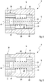
- FIGS. 3 to 5 show variants of an alternative embodiment of the first
- Non-return valve 9 in longitudinal section, wherein the second check valve 10 may be constructed the same, so that only the check valve 9 is described below.
- the non-return valve 9 has a valve housing 19 and a valve closing body 20 which is axially displaceable along a valve longitudinal axis L and which is biased against a valve seat 23 by means of a valve spring 22.
- the valve closing body 20 is provided guided in the valve housing 19 and has a mandrel-shaped guide body 25 which extends through the valve spring 22 in its entire length, so that it is guided.
- the mandrel-shaped guide body 25 is designed to be movable with the valve closing body 20 and immersed in the valve housing 19 or arranged in the valve housing 19 lid 35 provided.
- the guide body 25 can either in a recess 32 of a bottom 33 of the valve housing 19 (FIG. FIG. 3 ) or in a recess 34 of a lid 35 (FIG. FIGS. 4 and 5 ) be provided guided.
- the guide body 25 may be designed as a cylinder or as a plate.
- valve seat 23 is arranged on a closure element 36 fastened in the valve housing 19, which has an opening 37 which is assigned to the supply connection or the tank (not shown) and can be closed by means of the valve closing body 20.
- the bottom 33 has openings 38 for the flow of hydraulic fluid in the direction of the hydraulic chamber 4 (FIG. FIG. 1 ) on.
- a vent hole 39 is provided in the region of the recess 32.
- the valve closing body 20 may on its outside recesses or recesses 40 ( FIG. 3 and 5 ) or holes 30 ( FIG. 4 ) to the flow of hydraulic fluid.
- the base 24 of the valve housing 19 has an opening 29 arranged axially relative to the valve longitudinal axis L, which opening is assigned to the supply connection or the tank and can be closed by means of the valve closing body 20.
- the cover 35 has openings 41 for the passage of the hydraulic fluid in the direction of the hydraulic chamber 4 (FIG. FIG. 1 ) on. Further, a vent hole 42 is provided in the region of the recess 34.
- the improved construction of the check valves 9, 10 according to the invention allows the valve spring 22 to be guided over the entire length, so that no intermediate space can arise in which the valve spring 22 can get stuck in transverse forces and thus be destroyed.
- valve closing body 20 is considered advantageous that can be dispensed with radial bores in the valve housing 19, as this is preferably provided screwed into the connecting rod 1.
- the leadership of the valve closing body 20 can be improved.
Applications Claiming Priority (3)
| Application Number | Priority Date | Filing Date | Title |
|---|---|---|---|
| DE102015120359 | 2015-11-25 | ||
| DE102015120443 | 2015-11-25 | ||
| DE102016110279.2A DE102016110279A1 (de) | 2015-11-25 | 2016-06-03 | Rückschlagventil für ein Pleuel für eine variable Verdichtung einer Brennkraftmaschine sowie Pleuel mit einem derartigen Rückschlagventil |
Publications (2)
| Publication Number | Publication Date |
|---|---|
| EP3173601A1 true EP3173601A1 (fr) | 2017-05-31 |
| EP3173601B1 EP3173601B1 (fr) | 2018-03-14 |
Family
ID=57406055
Family Applications (1)
| Application Number | Title | Priority Date | Filing Date |
|---|---|---|---|
| EP16199578.2A Not-in-force EP3173601B1 (fr) | 2015-11-25 | 2016-11-18 | Clapet de non-retour pour une bielle pour une compression variable d'un moteur à combustion interne et bielle comprenant un tel clapet de non-retour |
Country Status (1)
| Country | Link |
|---|---|
| EP (1) | EP3173601B1 (fr) |
Citations (4)
| Publication number | Priority date | Publication date | Assignee | Title |
|---|---|---|---|---|
| DE102007018068A1 (de) * | 2006-12-14 | 2008-06-19 | Hyundai Motor Company | Rückschlagventil eines Zylinderkopfes |
| DE102007016625A1 (de) * | 2007-04-05 | 2008-10-09 | Continental Automotive Gmbh | Ventil und Einspritzanlage für eine Brennkraftmaschine mit Ventil |
| DE102012112481A1 (de) | 2012-12-18 | 2014-06-18 | Dr. Ing. H.C. F. Porsche Aktiengesellschaft | Rückschlagventil |
| EP2821619A1 (fr) * | 2013-07-05 | 2015-01-07 | Hilite Germany GmbH | Bielle pour une étanchéification variable en deux étapes |
-
2016
- 2016-11-18 EP EP16199578.2A patent/EP3173601B1/fr not_active Not-in-force
Patent Citations (5)
| Publication number | Priority date | Publication date | Assignee | Title |
|---|---|---|---|---|
| DE102007018068A1 (de) * | 2006-12-14 | 2008-06-19 | Hyundai Motor Company | Rückschlagventil eines Zylinderkopfes |
| DE102007016625A1 (de) * | 2007-04-05 | 2008-10-09 | Continental Automotive Gmbh | Ventil und Einspritzanlage für eine Brennkraftmaschine mit Ventil |
| DE102012112481A1 (de) | 2012-12-18 | 2014-06-18 | Dr. Ing. H.C. F. Porsche Aktiengesellschaft | Rückschlagventil |
| EP2821619A1 (fr) * | 2013-07-05 | 2015-01-07 | Hilite Germany GmbH | Bielle pour une étanchéification variable en deux étapes |
| DE102013107127A1 (de) | 2013-07-05 | 2015-01-08 | Hilite Germany Gmbh | Pleuel für eine zweistufige variable Verdichtung |
Also Published As
| Publication number | Publication date |
|---|---|
| EP3173601B1 (fr) | 2018-03-14 |
Similar Documents
| Publication | Publication Date | Title |
|---|---|---|
| DE102014106715A1 (de) | Umschaltventil und Verbrennungsmotor | |
| DE102012112461A1 (de) | Umschaltventil und Verbrennungsmotor mit einem derartigen Umschaltventil | |
| DE102013021065A1 (de) | Kolbenmaschine mit Stützkolben | |
| DE102010061360A1 (de) | Umschaltventil und Verbrennungsmotor mit einem derartigen Umschaltventil | |
| DE102016008306A1 (de) | Pleuel mit verstellbarer Pleuellänge | |
| DE102015110664A1 (de) | Umschaltventil und Verbrennungsmotor | |
| DE102016110279A1 (de) | Rückschlagventil für ein Pleuel für eine variable Verdichtung einer Brennkraftmaschine sowie Pleuel mit einem derartigen Rückschlagventil | |
| DE102017121443A1 (de) | Rückschlagventil für einen Pleuel einer Brennkraftmaschine mit variabler Verdichtung sowie Pleuel mit einem derartigen Rückschlagventil | |
| WO2018083256A1 (fr) | Bielle réglable en longueur comportant une unité cylindre-piston pourvue de plusieurs joints de piston | |
| DE102010061359A1 (de) | Umschaltventil und Verbrennungsmotor mit einem derartigen Umschaltventil | |
| WO2017162425A1 (fr) | Clapet anti-retour pour une bielle pour un moteur à combustion interne avec compression variable ainsi que bielle avec clapet anti-retour | |
| AT519156A1 (de) | Längenverstellbares Pleuel für eine Hubkolbenmaschine, Hubkolbenmaschine und Fahrzeug | |
| DE102015110663A1 (de) | Verbrennungsmotor | |
| EP3404232B1 (fr) | Bielle pour un moteur à combustion interne à compression variable | |
| EP3173601B1 (fr) | Clapet de non-retour pour une bielle pour une compression variable d'un moteur à combustion interne et bielle comprenant un tel clapet de non-retour | |
| DE102015210597A1 (de) | Hubkolbenmotor und Kraftfahrzeug | |
| DE102018118449A1 (de) | Rückschlagventil für einen Pleuel einer Brennkraftmaschine mit variabler Verdichtung sowie Pleuel mit einem Rückschlagventil | |
| DE102017113250A1 (de) | Kolben für eine Pleuelstange und Pleuelstange | |
| DE102017107719A1 (de) | Hydraulikventil zum Einstellen eines Hydraulikflüssigkeitsstroms eines Pleuels für eine Brennkraftmaschine mit variabler Verdichtung | |
| DE102017107682A1 (de) | Pleuel für eine Brennkraftmaschine mit variabler Verdichtung | |
| DE102016120943A1 (de) | Pleuelstange mit Verstellmechanismus zwischen Pleuelfuß und Kolbenstange | |
| DE102016117874A1 (de) | Umschaltventil zum Steuern eines Hydraulikflüssigkeitsstroms und Pleuel mit einem Umschaltventil | |
| EP3361069B1 (fr) | Bielle d'un moteur à combustion interne par compression variable pourvue d'une soupape de retenue | |
| DE102016104958A1 (de) | Rückschlagventil für ein Pleuel für eine Brennkraftmaschine mit variabler Verdichtung sowie Pleuel mit einem Rückschlagventil | |
| DE102015121918A1 (de) | Umschaltventil, Pleuelstange und Verbrennungsmotor |
Legal Events
| Date | Code | Title | Description |
|---|---|---|---|
| PUAI | Public reference made under article 153(3) epc to a published international application that has entered the european phase |
Free format text: ORIGINAL CODE: 0009012 |
|
| AK | Designated contracting states |
Kind code of ref document: A1 Designated state(s): AL AT BE BG CH CY CZ DE DK EE ES FI FR GB GR HR HU IE IS IT LI LT LU LV MC MK MT NL NO PL PT RO RS SE SI SK SM TR |
|
| AX | Request for extension of the european patent |
Extension state: BA ME |
|
| 17P | Request for examination filed |
Effective date: 20170502 |
|
| GRAP | Despatch of communication of intention to grant a patent |
Free format text: ORIGINAL CODE: EPIDOSNIGR1 |
|
| RIC1 | Information provided on ipc code assigned before grant |
Ipc: F16K 15/02 20060101ALN20170718BHEP Ipc: F02B 75/04 20060101AFI20170718BHEP |
|
| GRAS | Grant fee paid |
Free format text: ORIGINAL CODE: EPIDOSNIGR3 |
|
| INTG | Intention to grant announced |
Effective date: 20170823 |
|
| GRAA | (expected) grant |
Free format text: ORIGINAL CODE: 0009210 |
|
| RBV | Designated contracting states (corrected) |
Designated state(s): AL AT BE BG CH CY CZ DE DK EE ES FI FR GB GR HR HU IE IS IT LI LT LU LV MC MK MT NL NO PL PT RO RS SE SI SK SM TR |
|
| AK | Designated contracting states |
Kind code of ref document: B1 Designated state(s): AL AT BE BG CH CY CZ DE DK EE ES FI FR GB GR HR HU IE IS IT LI LT LU LV MC MK MT NL NO PL PT RO RS SE SI SK SM TR |
|
| REG | Reference to a national code |
Ref country code: GB Ref legal event code: FG4D Free format text: NOT ENGLISH |
|
| REG | Reference to a national code |
Ref country code: CH Ref legal event code: EP Ref country code: AT Ref legal event code: REF Ref document number: 979117 Country of ref document: AT Kind code of ref document: T Effective date: 20180315 |
|
| REG | Reference to a national code |
Ref country code: IE Ref legal event code: FG4D Free format text: LANGUAGE OF EP DOCUMENT: GERMAN |
|
| REG | Reference to a national code |
Ref country code: DE Ref legal event code: R096 Ref document number: 502016000718 Country of ref document: DE |
|
| REG | Reference to a national code |
Ref country code: NL Ref legal event code: MP Effective date: 20180314 |
|
| REG | Reference to a national code |
Ref country code: LT Ref legal event code: MG4D |
|
| PG25 | Lapsed in a contracting state [announced via postgrant information from national office to epo] |
Ref country code: LT Free format text: LAPSE BECAUSE OF FAILURE TO SUBMIT A TRANSLATION OF THE DESCRIPTION OR TO PAY THE FEE WITHIN THE PRESCRIBED TIME-LIMIT Effective date: 20180314 Ref country code: CY Free format text: LAPSE BECAUSE OF FAILURE TO SUBMIT A TRANSLATION OF THE DESCRIPTION OR TO PAY THE FEE WITHIN THE PRESCRIBED TIME-LIMIT Effective date: 20180314 Ref country code: HR Free format text: LAPSE BECAUSE OF FAILURE TO SUBMIT A TRANSLATION OF THE DESCRIPTION OR TO PAY THE FEE WITHIN THE PRESCRIBED TIME-LIMIT Effective date: 20180314 Ref country code: FI Free format text: LAPSE BECAUSE OF FAILURE TO SUBMIT A TRANSLATION OF THE DESCRIPTION OR TO PAY THE FEE WITHIN THE PRESCRIBED TIME-LIMIT Effective date: 20180314 Ref country code: NO Free format text: LAPSE BECAUSE OF FAILURE TO SUBMIT A TRANSLATION OF THE DESCRIPTION OR TO PAY THE FEE WITHIN THE PRESCRIBED TIME-LIMIT Effective date: 20180614 |
|
| PG25 | Lapsed in a contracting state [announced via postgrant information from national office to epo] |
Ref country code: RS Free format text: LAPSE BECAUSE OF FAILURE TO SUBMIT A TRANSLATION OF THE DESCRIPTION OR TO PAY THE FEE WITHIN THE PRESCRIBED TIME-LIMIT Effective date: 20180314 Ref country code: SE Free format text: LAPSE BECAUSE OF FAILURE TO SUBMIT A TRANSLATION OF THE DESCRIPTION OR TO PAY THE FEE WITHIN THE PRESCRIBED TIME-LIMIT Effective date: 20180314 Ref country code: LV Free format text: LAPSE BECAUSE OF FAILURE TO SUBMIT A TRANSLATION OF THE DESCRIPTION OR TO PAY THE FEE WITHIN THE PRESCRIBED TIME-LIMIT Effective date: 20180314 Ref country code: GR Free format text: LAPSE BECAUSE OF FAILURE TO SUBMIT A TRANSLATION OF THE DESCRIPTION OR TO PAY THE FEE WITHIN THE PRESCRIBED TIME-LIMIT Effective date: 20180615 Ref country code: BG Free format text: LAPSE BECAUSE OF FAILURE TO SUBMIT A TRANSLATION OF THE DESCRIPTION OR TO PAY THE FEE WITHIN THE PRESCRIBED TIME-LIMIT Effective date: 20180614 |
|
| PG25 | Lapsed in a contracting state [announced via postgrant information from national office to epo] |
Ref country code: MT Free format text: LAPSE BECAUSE OF FAILURE TO SUBMIT A TRANSLATION OF THE DESCRIPTION OR TO PAY THE FEE WITHIN THE PRESCRIBED TIME-LIMIT Effective date: 20180314 |
|
| PG25 | Lapsed in a contracting state [announced via postgrant information from national office to epo] |
Ref country code: AL Free format text: LAPSE BECAUSE OF FAILURE TO SUBMIT A TRANSLATION OF THE DESCRIPTION OR TO PAY THE FEE WITHIN THE PRESCRIBED TIME-LIMIT Effective date: 20180314 Ref country code: ES Free format text: LAPSE BECAUSE OF FAILURE TO SUBMIT A TRANSLATION OF THE DESCRIPTION OR TO PAY THE FEE WITHIN THE PRESCRIBED TIME-LIMIT Effective date: 20180314 Ref country code: RO Free format text: LAPSE BECAUSE OF FAILURE TO SUBMIT A TRANSLATION OF THE DESCRIPTION OR TO PAY THE FEE WITHIN THE PRESCRIBED TIME-LIMIT Effective date: 20180314 Ref country code: NL Free format text: LAPSE BECAUSE OF FAILURE TO SUBMIT A TRANSLATION OF THE DESCRIPTION OR TO PAY THE FEE WITHIN THE PRESCRIBED TIME-LIMIT Effective date: 20180314 Ref country code: EE Free format text: LAPSE BECAUSE OF FAILURE TO SUBMIT A TRANSLATION OF THE DESCRIPTION OR TO PAY THE FEE WITHIN THE PRESCRIBED TIME-LIMIT Effective date: 20180314 Ref country code: IT Free format text: LAPSE BECAUSE OF FAILURE TO SUBMIT A TRANSLATION OF THE DESCRIPTION OR TO PAY THE FEE WITHIN THE PRESCRIBED TIME-LIMIT Effective date: 20180314 Ref country code: PL Free format text: LAPSE BECAUSE OF FAILURE TO SUBMIT A TRANSLATION OF THE DESCRIPTION OR TO PAY THE FEE WITHIN THE PRESCRIBED TIME-LIMIT Effective date: 20180314 |
|
| PG25 | Lapsed in a contracting state [announced via postgrant information from national office to epo] |
Ref country code: SK Free format text: LAPSE BECAUSE OF FAILURE TO SUBMIT A TRANSLATION OF THE DESCRIPTION OR TO PAY THE FEE WITHIN THE PRESCRIBED TIME-LIMIT Effective date: 20180314 Ref country code: CZ Free format text: LAPSE BECAUSE OF FAILURE TO SUBMIT A TRANSLATION OF THE DESCRIPTION OR TO PAY THE FEE WITHIN THE PRESCRIBED TIME-LIMIT Effective date: 20180314 Ref country code: SM Free format text: LAPSE BECAUSE OF FAILURE TO SUBMIT A TRANSLATION OF THE DESCRIPTION OR TO PAY THE FEE WITHIN THE PRESCRIBED TIME-LIMIT Effective date: 20180314 |
|
| REG | Reference to a national code |
Ref country code: DE Ref legal event code: R097 Ref document number: 502016000718 Country of ref document: DE |
|
| PG25 | Lapsed in a contracting state [announced via postgrant information from national office to epo] |
Ref country code: PT Free format text: LAPSE BECAUSE OF FAILURE TO SUBMIT A TRANSLATION OF THE DESCRIPTION OR TO PAY THE FEE WITHIN THE PRESCRIBED TIME-LIMIT Effective date: 20180716 |
|
| PLBE | No opposition filed within time limit |
Free format text: ORIGINAL CODE: 0009261 |
|
| STAA | Information on the status of an ep patent application or granted ep patent |
Free format text: STATUS: NO OPPOSITION FILED WITHIN TIME LIMIT |
|
| PG25 | Lapsed in a contracting state [announced via postgrant information from national office to epo] |
Ref country code: DK Free format text: LAPSE BECAUSE OF FAILURE TO SUBMIT A TRANSLATION OF THE DESCRIPTION OR TO PAY THE FEE WITHIN THE PRESCRIBED TIME-LIMIT Effective date: 20180314 |
|
| 26N | No opposition filed |
Effective date: 20181217 |
|
| PG25 | Lapsed in a contracting state [announced via postgrant information from national office to epo] |
Ref country code: MC Free format text: LAPSE BECAUSE OF FAILURE TO SUBMIT A TRANSLATION OF THE DESCRIPTION OR TO PAY THE FEE WITHIN THE PRESCRIBED TIME-LIMIT Effective date: 20180314 Ref country code: LU Free format text: LAPSE BECAUSE OF NON-PAYMENT OF DUE FEES Effective date: 20181118 |
|
| REG | Reference to a national code |
Ref country code: BE Ref legal event code: MM Effective date: 20181130 |
|
| REG | Reference to a national code |
Ref country code: IE Ref legal event code: MM4A |
|
| PG25 | Lapsed in a contracting state [announced via postgrant information from national office to epo] |
Ref country code: IE Free format text: LAPSE BECAUSE OF NON-PAYMENT OF DUE FEES Effective date: 20181118 |
|
| PG25 | Lapsed in a contracting state [announced via postgrant information from national office to epo] |
Ref country code: BE Free format text: LAPSE BECAUSE OF NON-PAYMENT OF DUE FEES Effective date: 20181130 |
|
| PGFP | Annual fee paid to national office [announced via postgrant information from national office to epo] |
Ref country code: FR Payment date: 20191120 Year of fee payment: 4 |
|
| PG25 | Lapsed in a contracting state [announced via postgrant information from national office to epo] |
Ref country code: TR Free format text: LAPSE BECAUSE OF FAILURE TO SUBMIT A TRANSLATION OF THE DESCRIPTION OR TO PAY THE FEE WITHIN THE PRESCRIBED TIME-LIMIT Effective date: 20180314 |
|
| PG25 | Lapsed in a contracting state [announced via postgrant information from national office to epo] |
Ref country code: HU Free format text: LAPSE BECAUSE OF FAILURE TO SUBMIT A TRANSLATION OF THE DESCRIPTION OR TO PAY THE FEE WITHIN THE PRESCRIBED TIME-LIMIT; INVALID AB INITIO Effective date: 20161118 Ref country code: MK Free format text: LAPSE BECAUSE OF NON-PAYMENT OF DUE FEES Effective date: 20180314 |
|
| REG | Reference to a national code |
Ref country code: CH Ref legal event code: PL |
|
| PG25 | Lapsed in a contracting state [announced via postgrant information from national office to epo] |
Ref country code: LI Free format text: LAPSE BECAUSE OF NON-PAYMENT OF DUE FEES Effective date: 20191130 Ref country code: CH Free format text: LAPSE BECAUSE OF NON-PAYMENT OF DUE FEES Effective date: 20191130 Ref country code: IS Free format text: LAPSE BECAUSE OF FAILURE TO SUBMIT A TRANSLATION OF THE DESCRIPTION OR TO PAY THE FEE WITHIN THE PRESCRIBED TIME-LIMIT Effective date: 20180714 |
|
| PG25 | Lapsed in a contracting state [announced via postgrant information from national office to epo] |
Ref country code: SI Free format text: LAPSE BECAUSE OF NON-PAYMENT OF DUE FEES Effective date: 20181118 |
|
| GBPC | Gb: european patent ceased through non-payment of renewal fee |
Effective date: 20201118 |
|
| PG25 | Lapsed in a contracting state [announced via postgrant information from national office to epo] |
Ref country code: FR Free format text: LAPSE BECAUSE OF NON-PAYMENT OF DUE FEES Effective date: 20201130 |
|
| PG25 | Lapsed in a contracting state [announced via postgrant information from national office to epo] |
Ref country code: GB Free format text: LAPSE BECAUSE OF NON-PAYMENT OF DUE FEES Effective date: 20201118 |
|
| PGFP | Annual fee paid to national office [announced via postgrant information from national office to epo] |
Ref country code: DE Payment date: 20211118 Year of fee payment: 6 |
|
| REG | Reference to a national code |
Ref country code: AT Ref legal event code: MM01 Ref document number: 979117 Country of ref document: AT Kind code of ref document: T Effective date: 20211118 |
|
| PG25 | Lapsed in a contracting state [announced via postgrant information from national office to epo] |
Ref country code: AT Free format text: LAPSE BECAUSE OF NON-PAYMENT OF DUE FEES Effective date: 20211118 |
|
| REG | Reference to a national code |
Ref country code: DE Ref legal event code: R119 Ref document number: 502016000718 Country of ref document: DE |
|
| PG25 | Lapsed in a contracting state [announced via postgrant information from national office to epo] |
Ref country code: DE Free format text: LAPSE BECAUSE OF NON-PAYMENT OF DUE FEES Effective date: 20230601 |