EP3173601A1 - Non-return valve for a connecting rod for a variable compression of an internal combustion engine, and connecting rod with such a non-return valve - Google Patents
Non-return valve for a connecting rod for a variable compression of an internal combustion engine, and connecting rod with such a non-return valve Download PDFInfo
- Publication number
- EP3173601A1 EP3173601A1 EP16199578.2A EP16199578A EP3173601A1 EP 3173601 A1 EP3173601 A1 EP 3173601A1 EP 16199578 A EP16199578 A EP 16199578A EP 3173601 A1 EP3173601 A1 EP 3173601A1
- Authority
- EP
- European Patent Office
- Prior art keywords
- valve
- closing body
- valve closing
- check valve
- connecting rod
- Prior art date
- Legal status (The legal status is an assumption and is not a legal conclusion. Google has not performed a legal analysis and makes no representation as to the accuracy of the status listed.)
- Granted
Links
Images

Classifications
-
- F—MECHANICAL ENGINEERING; LIGHTING; HEATING; WEAPONS; BLASTING
- F02—COMBUSTION ENGINES; HOT-GAS OR COMBUSTION-PRODUCT ENGINE PLANTS
- F02B—INTERNAL-COMBUSTION PISTON ENGINES; COMBUSTION ENGINES IN GENERAL
- F02B75/00—Other engines
- F02B75/04—Engines with variable distances between pistons at top dead-centre positions and cylinder heads
- F02B75/045—Engines with variable distances between pistons at top dead-centre positions and cylinder heads by means of a variable connecting rod length
-
- F—MECHANICAL ENGINEERING; LIGHTING; HEATING; WEAPONS; BLASTING
- F16—ENGINEERING ELEMENTS AND UNITS; GENERAL MEASURES FOR PRODUCING AND MAINTAINING EFFECTIVE FUNCTIONING OF MACHINES OR INSTALLATIONS; THERMAL INSULATION IN GENERAL
- F16K—VALVES; TAPS; COCKS; ACTUATING-FLOATS; DEVICES FOR VENTING OR AERATING
- F16K15/00—Check valves
- F16K15/02—Check valves with guided rigid valve members
- F16K15/025—Check valves with guided rigid valve members the valve being loaded by a spring
- F16K15/026—Check valves with guided rigid valve members the valve being loaded by a spring the valve member being a movable body around which the medium flows when the valve is open
Abstract
Die Erfindung betrifft ein Rückschlagventil (9, 10) für ein Pleuel (1) für eine variable Verdichtung einer Brennkraftmaschine mit wenigstens einer Hydraulikkammer (4, 5), wobei die Hydraulikkammer (4, 5) des Pleuels (1) mittels des Rückschlagventils (9, 10) mit einem Versorgungsanschluss bzw. einem Tank verbindbar ist, und wobei das Rückschlagventil (9, 10) ein Ventilgehäuse (19) und einen entlang einer Ventillängsachse (L) axial zwischen einer geöffneten und einer geschlossenen Position verschieblichen Ventilschließkörper (20) aufweist, welcher mittels einer Ventilfeder (22) gegen einen Ventilsitz (23) vorgespannt ist. Erfindungsgemäß ist ein dornförmiger Führungskörper (25) vorgesehen, welcher die Ventilfeder (22) durchragt und mittels welchem die Ventilfeder (22) sowohl in der geöffneten Position als auch in der geschlossenen Position des Ventilschließkörpers (20) geführt ist. Ferner betrifft die Erfindung ein Pleuel (1) mit wenigstens einem Rückschlagventil (9, 10).The invention relates to a check valve (9, 10) for a connecting rod (1) for variable compression of an internal combustion engine having at least one hydraulic chamber (4, 5), wherein the hydraulic chamber (4, 5) of the connecting rod (1) by means of the check valve (9 10) is connectable to a supply connection or a tank, and wherein the check valve (9, 10) has a valve housing (19) and a valve closing body (20) displaceable axially between an open and a closed position along a valve longitudinal axis (L); which is biased by a valve spring (22) against a valve seat (23). According to the invention, a mandrel-shaped guide body (25) is provided, which projects through the valve spring (22) and by means of which the valve spring (22) is guided both in the open position and in the closed position of the valve closing body (20). Furthermore, the invention relates to a connecting rod (1) with at least one check valve (9, 10).
Description
Die Erfindung betrifft ein Rückschlagventil für ein Pleuel für eine variable Verdichtung einer Brennkraftmaschine mit wenigstens einer Hydraulikkammer, wobei die Hydraulikkammer des Pleuels mittels des Rückschlagventils mit einem Versorgungsanschluss bzw. einem Tank verbindbar ist, wobei das Rückschlagventil ein topfförmiges Ventilgehäuse und einen entlang einer Ventillängsachse axial verschieblichen Ventilschließkörper aufweist, welcher mittels einer Ventilfeder gegen einen Ventilsitz vorgespannt ist, sowie ein Pleuel mit einem derartigen Rückschlagventil.The invention relates to a check valve for a connecting rod for a variable compression of an internal combustion engine with at least one hydraulic chamber, wherein the hydraulic chamber of the connecting rod is connectable by means of the check valve with a supply port or a tank, wherein the check valve a cup-shaped valve housing and along a valve longitudinal axis axially displaceable Valve-closing body which is biased by a valve spring against a valve seat, and a connecting rod with such a check valve.
Bei Brennkraftmaschinen wirkt sich ein hohes Verdichtungsverhältnis positiv auf den Wirkungsgrad der Brennkraftmaschine aus. Unter Verdichtungsverhältnis wird im Allgemeinen das Verhältnis des gesamten Zylinderraumes vor der Verdichtung zum verbliebenen Zylinderraum nach der Verdichtung verstanden. Bei Brennkraftmaschinen mit Fremdzündung, insbesondere Ottomotoren, die ein festes Verdichtungsverhältnis aufweisen, darf das Verdichtungsverhältnis jedoch nur so hoch gewählt werden, dass bei Volllastbetrieb ein sogenanntes "Klopfen" der Brennkraftmaschine vermieden wird. Jedoch könnte für den weitaus häufiger auftretenden Teillastbereich der Brennkraftmaschine, also bei geringer Zylinderfüllung, das Verdichtungsverhältnis mit höheren Werten gewählt werden, ohne dass ein "Klopfen" auftreten würde. Der wichtige Teillastbereich einer Brennkraftmaschine kann verbessert werden, wenn das Verdichtungsverhältnis variabel einstellbar ist. Zur Verstellung des Verdichtungsverhältnisses sind beispielsweise Systeme mit variabler Pleuelstangenlänge bekannt, welche mit Hilfe von hydraulischen Umschaltventilen eine Exzenter-Verstelleinrichtung eines Pleuels betätigen.In internal combustion engines, a high compression ratio has a positive effect on the efficiency of the internal combustion engine. Under compression ratio is generally understood the ratio of the entire cylinder space before compression to the remaining cylinder space after compression. In internal combustion engines with spark ignition, in particular gasoline engines, which have a fixed compression ratio, the compression ratio, however, may only be selected so high that a so-called "knocking" of the internal combustion engine is avoided during full load operation. However, for the far more frequently occurring partial load range of the internal combustion engine, that is to say with low cylinder filling, the compression ratio could be selected with higher values, without any "knocking". would occur. The important part load range of an internal combustion engine can be improved if the compression ratio is variably adjustable. To adjust the compression ratio, systems with variable connecting rod length are known, for example, which actuate an eccentric adjustment of a connecting rod with the aid of hydraulic changeover valves.
Ein derartiges Pleuel ist beispielsweise aus der
Aus der
Eine Aufgabe der Erfindung ist es, ein anderes, verbessertes Rückschlagventil und ferner ein verbessertes Pleuel mit einem Rückschlagventil zu schaffen.An object of the invention is to provide another improved check valve and further an improved connecting rod with a check valve.
Die vorgenannten Aufgaben werden gelöst mit den Merkmalen der unabhängigen Ansprüche.The aforementioned objects are achieved with the features of the independent claims.
Günstige Ausgestaltungen und Vorteile der Erfindung ergeben sich aus den weiteren Ansprüchen, der Beschreibung und der Zeichnung.Favorable embodiments and advantages of the invention will become apparent from the other claims, the description and the drawings.
Die Erfindung geht aus von einem Rückschlagventil für ein Pleuel für eine variable Verdichtung einer Brennkraftmaschine mit wenigstens einer Hydraulikkammer, wobei die Hydraulikkammer des Pleuels mittels des Rückschlagventils mit einem Versorgungsanschluss bzw. einem Tank verbindbar ist, und wobei das Rückschlagventil ein Ventilgehäuse und einen entlang einer Ventillängsachse axial zwischen einer geöffneten und einer geschlossenen Position verschieblichen Ventilschließkörper aufweist, welcher mittels einer Ventilfeder gegen einen Ventilsitz vorgespannt ist.The invention is based on a check valve for a connecting rod for variable compression of an internal combustion engine having at least one hydraulic chamber, wherein the hydraulic chamber of the connecting rod is connectable by means of the check valve with a supply port or a tank, and wherein the check valve, a valve housing and along a valve longitudinal axis axially between an open and a closed position having displaceable valve closing body, which is biased by a valve spring against a valve seat.
Es wird vorgeschlagen, dass ein dornförmiger Führungskörper vorgesehen ist, welcher die Ventilfeder durchragt und mittels welchem die Ventilfeder sowohl in der geöffneten Position als auch in der geschlossenen Position des Ventilschließkörpers geführt ist.It is proposed that a mandrel-shaped guide body is provided, which projects through the valve spring and by means of which the valve spring is guided both in the open position and in the closed position of the valve closing body.
Vorteilhaft kann durch die Führung der Ventilfeder vermieden werden, dass die Ventilfeder beim Öffnen oder Schließen des Rückschlagventils verkantet oder verklemmt. Der Führungskörper erstreckt sich vorteilhaft zumindest von einem Ende der Ventilfeder bis zum gegenüberliegenden Ende der Ventilfeder, d.h. in ihrer gesamten Länge, sowohl im gestauchten als auch im gestreckten Betriebszustand der Ventilfeder. Günstigerweise erlaubt die Konstruktion des Rückschlagventils eine Hubbegrenzung des Ventilschließkörpers.Advantageously can be avoided by the leadership of the valve spring that the valve spring tilted or jammed when opening or closing the check valve. The guide body advantageously extends at least from one end of the valve spring to the opposite end of the valve spring, i. in its entire length, both in the compressed and in the extended operating state of the valve spring. Conveniently, the construction of the check valve allows a stroke limitation of the valve closing body.
Die Erfindung erlaubt eine Führung der Ventilfeder über die ganze Länge, so dass kein Zwischenraum entstehen kann, in welchen die Ventilfeder bei Querkräften hineingeraten und somit verkanten oder zerstört werden kann. Die Betriebssicherheit des Rückschlagventils ist verbessert. Der Führungskörper kann in dem Ventilschließkörper geführt sein. Ist die Ventilfeder auf dem Ventilschließkörper als Führungskörper angeordnet, kann der Ventilschließkörper auf seinem ganzen Umfang geführt werden. Ein Verkippen desselben ist somit ausgeschlossen.The invention allows a guide of the valve spring over the entire length, so that no gap can arise in which the valve spring hineingeraten in transverse forces and thus tilt or can be destroyed. The reliability of the check valve is improved. The guide body may be guided in the valve closing body. If the valve spring is arranged on the valve closing body as a guide body, the valve closing body can be guided over its entire circumference. A tilting of the same is thus excluded.
Vorteilhafterweise ist der Ventilschließkörper in dem Ventilgehäuse geführt vorgesehen. Damit steht dem Ventilschließkörper eine vergleichsweise lange Führungsstrecke zur Verfügung, so dass auch ein Verkippen oder Verkanten des Ventilschließkörpers ausgeschlossen ist.Advantageously, the valve closing body is provided guided in the valve housing. This is the valve closing body a comparatively long guide path available, so that tilting or tilting of the valve closing body is excluded.
Nach einer günstigen Ausgestaltung einer ersten Ausführung des Rückschlagventils der dornförmige Führungskörper ortsfest mit dem Ventilgehäuse ausgebildet und in den Ventilschließkörper eintauchbar vorgesehen sein.According to a favorable embodiment of a first embodiment of the check valve, the mandrel-shaped guide body is formed stationary with the valve housing and be provided submersible in the valve closing body.
Dabei ist es für die Führung des Ventilschließkörpers vorteilhaft, wenn der Ventilschließkörper als Ventilschließkolben ausgebildet ist, welcher mittels der Ventilfeder gegen einen Boden des Ventilgehäuses als Ventilsitz vorgespannt ist, wobei die Ventilfeder mittels des in dem Ventilschließkolben geführten Führungskörpers des Halteelementes geführt vorgesehen ist. Nach einer günstigen Ausgestaltung kann das Ventilgehäuse topfförmig ausgebildet sein. Dies erlaubt eine einfache Herstellung des Ventilgehäuses. Vorteilhaft kann das Ventilgehäuse ein Einschraubgehäuse sein, das einfach in ein Pleuel eingeschraubt werden kann.It is advantageous for the guidance of the valve closing body, when the valve closing body is designed as a valve closing piston, which is biased by the valve spring against a bottom of the valve housing as a valve seat, wherein the valve spring is guided by means guided in the valve closing piston guide body of the holding element. According to a favorable embodiment, the valve housing may be cup-shaped. This allows a simple production of the valve housing. Advantageously, the valve housing may be a Einschraubgehäuse that can be easily screwed into a connecting rod.
Nach einer günstigen Ausgestaltung kann der Boden des Ventilgehäuses eine bezogen auf die Ventillängsachse axial angeordnete Öffnung aufweisen, welche dem Versorgungsanschluss bzw. dem Tank zugeordnet und mittels des Ventilschließkolbens verschließbar ist. Dies erlaubt eine einfache Herstellung des Versorgungsanschlusses des Ventilgehäuses.According to a favorable embodiment, the bottom of the valve housing may have an opening arranged axially relative to the valve longitudinal axis, which opening is assigned to the supply connection or to the tank and can be closed by means of the valve closing piston. This allows a simple production of the supply connection of the valve housing.
Nach einer günstigen Ausgestaltung können ein oder mehrere Axialbohrungen im Ventilschließkolben vorgesehen sein, um bei Öffnung des Ventilschließkörpers einen Durchfluss von Hydraulikflüssigkeit in Richtung Hydraulikkammer zu ermöglichen. Durch die Axialbohrungen im Ventilschließkolben kann auf aufwändige Radialbohrungen im Ventilgehäuse verzichtet werden und der Ventilschließkolben auf seinem ganzen Umfang geführt sein.According to a favorable embodiment, one or more axial bores may be provided in the valve-closing piston in order to allow a flow of hydraulic fluid in the direction of the hydraulic chamber when opening the valve-closing body. Due to the axial bores in the valve closing piston can be dispensed with elaborate radial bores in the valve housing and the valve closing piston to be guided over its entire circumference.
Nach einer günstigen Ausgestaltung kann der Ventilschließkörper einen Innenraum aufweisen, in welchen der Führungskörper geführt vorgesehen und in welchen der Führungskörper bei Öffnung des Ventilschließkörpers eintauchbar ist. Dies erlaubt eine zuverlässige Betätigung des Ventilschließkörpers sowie eine sichere Führung der Ventilfeder auf ihrer ganzen Länge.According to a favorable embodiment, the valve closing body may have an interior, in which the guide body is provided guided and in which the guide body is immersed in opening the valve closing body. This allows a reliable actuation of the valve closing body and a secure guidance of the valve spring over its entire length.
Nach einer günstigen Ausgestaltung kann der Ventilschließkörper ein oder mehrere radiale Entlüftungsbohrungen aufweisen, welche in die Axialbohrungen münden. Vorteilhaft kann der Ventilschließkörper zum Führungskörper entlüftet werdenAccording to a favorable embodiment of the valve closing body may have one or more radial vent holes, which open into the axial bores. Advantageously, the valve closing body can be vented to the guide body
In einer alternativen zweiten Ausführung des Rückschlagventils kann der dornförmige Führungskörper mit dem Ventilschließkörper bewegbar ausgebildet und in das Ventilgehäuse oder einem in dem Ventilgehäuse angeordneten Deckel eintauchbar vorgesehen sein.In an alternative second embodiment of the check valve, the mandrel-shaped guide body can be designed to be movable with the valve closing body and be provided so as to be submersible in the valve housing or a cover arranged in the valve housing.
Vorzugsweise kann dabei der Ventilschließkörper den dornförmigen Führungskörper aufweisen, mittels welchem die Ventilfeder geführt ist, wobei der Führungskörper in dem Ventilgehäuse oder einem in dem Ventilgehäuse angeordneten Deckel führbar ist. Der Deckel kann günstig in das Ventilgehäuse eingepresst sein.Preferably, the valve closing body may comprise the mandrel-shaped guide body, by means of which the valve spring is guided, wherein the guide body in the valve housing or a cover arranged in the valve housing is feasible. The lid can be pressed into the valve housing.
Nach einer günstigen Ausgestaltung dieser alternativen Ausführung kann ein Verschlusselement des Ventilgehäuses eine bezogen auf die Ventillängsachse axial angeordnete Öffnung aufweisen, welche dem Versorgungsanschluss bzw. dem Tank zugeordnet und mittels des Ventilschließkörpers verschließbar ist. Dies erlaubt eine einfache Konstruktion des Rückschlagventils.According to a favorable embodiment of this alternative embodiment, a closure element of the valve housing axially relative to the valve longitudinal axis Having arranged opening which is assigned to the supply port or the tank and closed by means of the valve closing body. This allows a simple construction of the check valve.
Nach einer alternativen günstigen Ausgestaltung dieser alternativen Ausführung kann der Boden des Ventilgehäuses eine bezogen auf die Ventillängsachse axial angeordnete Öffnung aufweisen, welche dem Versorgungsanschluss bzw. dem Tank zugeordnet und mittels des Ventilschließkörpers verschließbar ist. Dies erlaubt eine einfache Konstruktion des Rückschlagventils.According to an alternative favorable embodiment of this alternative embodiment, the bottom of the valve housing may have an axially disposed relative to the longitudinal axis of the valve opening, which is associated with the supply port or the tank and closed by means of the valve closing body. This allows a simple construction of the check valve.
Nach einer günstigen Ausgestaltung dieser alternativen Ausführung können ein oder mehrere Axialbohrungen im Ventilschließkörper vorgesehen sein, um bei Öffnung des Ventilschließkörpers einen Durchfluss von Hydraulikflüssigkeit in Richtung Hydraulikkammer zu ermöglichen.According to a favorable embodiment of this alternative embodiment, one or more axial bores may be provided in the valve closing body in order to allow a flow of hydraulic fluid in the direction of the hydraulic chamber when opening the valve closing body.
Alternativ hierzu kann der Ventilschließkörper ein oder mehrere Vertiefungen aufweisen, um bei Öffnung des Ventilschließkörpers einen Durchfluss von Hydraulikflüssigkeit in Richtung Hydraulikkammer zu ermöglichen.Alternatively, the valve closing body may have one or more depressions in order to allow a flow of hydraulic fluid in the direction of the hydraulic chamber when opening the valve closing body.
Als Material für das Rückschlagventil kann in den genannten Ausführungen vorteilhaft Stahl, Aluminium, Aluminiumlegierung oder Kunststoff verwendet sein.As a material for the check valve can be used in the aforementioned embodiments advantageous steel, aluminum, aluminum alloy or plastic.
Nach einer weiteren Aspekt der Erfindung wird ein Pleuel vorgeschlagen für eine variable Verdichtung einer Brennkraftmaschine mit wenigstens einer Hydraulikkammer, wobei die Hydraulikkammer mittels eines Rückschlagventils gemäß einem oder mehreren der vorstehend beschriebenen Merkmalen mit einem Versorgungsanschluss bzw. einer Lagerschale bzw. einem Tank des Pleuels verbindbar ist.According to a further aspect of the invention, a connecting rod is proposed for a variable compression of an internal combustion engine having at least one hydraulic chamber, wherein the hydraulic chamber is connectable by means of a check valve according to one or more of the features described above with a supply connection or a bearing shell or a tank of the connecting rod ,
Die Rückschlagventile des Pleuels können identisch aufgebaut sein, oder eines der Rückschlagventile kann entsprechend der ersten beschriebenen Ausführung und das andere der Rückschlagventile entsprechend der zweiten Ausführung ausgebildet seinThe check valves of the connecting rod may be identically constructed, or one of the check valves may be formed according to the first described embodiment and the other of the check valves according to the second embodiment
Weitere Vorteile ergeben sich aus der folgenden Zeichnungsbeschreibung. In den Zeichnungen ist ein Ausführungsbeispiel der Erfindung schematisch dargestellt. Die Zeichnungen, die Beschreibung und die Ansprüche enthalten zahlreiche Merkmale in Kombination. Der Fachmann wird die Merkmale zweckmäßigerweise auch einzeln betrachten und zu sinnvollen weiteren Kombinationen zusammenfassen.Further advantages emerge from the following description of the drawing. In the drawings, an embodiment of the invention is shown schematically. The drawings, the description and the claims contain numerous features in combination. The person skilled in the art will expediently also consider the features individually and combine them into meaningful further combinations.
Es zeigen:
- Fig. 1
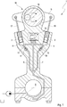
- ein Pleuel nach einer Ausgestaltung der Erfindung;
- Fig. 2
- ein Rückschlagventil nach einem Ausführungsbeispiel der Erfindung im Längsschnitt, bei dem eine Ventilfeder auf einem Führungskörper geführt ist, der in einem Ventilschließkörper geführt ist;
- Fig. 3
- ein Rückschlagventil nach einem weiteren Ausführungsbeispiel der Erfindung im Längsschnitt, bei dem eine Ventilfeder auf einem Ventilschließkörper als Führungskörper geführt ist;
- Fig.4
- ein Rückschlagventil nach einem weiteren Ausführungsbeispiel der Erfindung im Längsschnitt, bei dem eine Ventilfeder auf einem Ventilschließkörper als Führungskörper geführt ist; und
- Fig. 5
- ein Rückschlagventil nach einem weiteren Ausführungsbeispiel der Erfindung im Längsschnitt, bei dem eine Ventilfeder auf einem Ventilschließkörper als Führungskörper geführt ist.
- Fig. 1
- a connecting rod according to an embodiment of the invention;
- Fig. 2
- a check valve according to an embodiment of the invention in longitudinal section, in which a valve spring is guided on a guide body, which is guided in a valve closing body;
- Fig. 3
- a check valve according to a further embodiment of the invention in longitudinal section, in which a valve spring is guided on a valve closing body as a guide body;
- Figure 4
- a check valve according to a further embodiment of the invention in longitudinal section, in which a valve spring is guided on a valve closing body as a guide body; and
- Fig. 5
- a check valve according to a further embodiment of the invention in longitudinal section, in which a valve spring is guided on a valve closing body as a guide body.
In den Figuren sind gleiche oder gleichartige Komponenten mit gleichen Bezugszeichen beziffert. Die Figuren zeigen lediglich Beispiele und sind nicht beschränkend zu verstehen.In the figures, the same or similar components are numbered with the same reference numerals. The figures are merely examples and are not intended to be limiting.
Eine Verdrehung der verstellbaren Exzenter-Verstelleinrichtung 14 wird durch Einwirken von Massen- und Lastkräften des Verbrennungsmotors initiiert, die bei einem Arbeitstakt des Verbrennungsmotors auf die Exzenter-Verstelleinrichtung wirken. Während eines Arbeitstaktes verändern sich die Wirkungsrichtungen der auf die Exzenter-Verstelleinrichtung 14 wirkenden Kräfte kontinuierlich. Die Drehbewegung oder Verstellbewegung wird durch einen oder mehreren mit Hydraulikflüssigkeit, insbesondere mit Motoröl, beaufschlagte, im Pleuel 1 integrierte Kolben 2, 3 unterstützt, bzw. die Kolben 2, 3 verhindern ein Rückstellen der Exzenter-Verstelleinrichtung 14 aufgrund variierender Kraftwirkungsrichtungen der auf die Exzenter-Verstelleinrichtung 14 wirkenden Kräfte.A rotation of the adjustable
Die Kolben 2, 3 sind mittels Exzenterstangen 17, 18 beidseitig mit dem Exzenterhebel 15 wirkverbunden. Die Kolben 2, 3 sind in Hydraulikkammern 4, 5 verschiebbar angeordnet und über Hydraulikflüssigkeitsleitungen 6, 7 von dem Hublagerauge 8 aus mit Hydraulikflüssigkeit über Rückschlagventile 9, 10 beaufschlagt, deren Aufbau im nachfolgenden näher erläutert wird. Diese in
Das Rückschlagventil 9 weist ein topfförmiges Ventilgehäuse 19 und einen entlang einer Ventillängsachse L axial verschieblichen Ventilschließkörper 20 auf, welcher mittels einer zwischen dem Ventilschließkörper 20 und einem in dem Ventilgehäuse 19 befestigten Halteelement 21 angeordneten Ventilfeder 22 gegen einen Ventilsitz 23 vorgespannt ist.The
Der Ventilschließkörper 20 ist als Ventilschließkolben ausgebildet, welcher in dem Ventilgehäuse 19 geführt und mittels der Ventilfeder 22 gegen einen Boden 24 des Ventilgehäuses 19 als Ventilsitz vorgespannt ist. Die Ventilfeder 22 ist mittels eines dornförmigen, in dem Ventilschließkolben 20 geführten Führungskörpers 25 des Halteelementes 21 geführt vorgesehen. Der dornförmige Führungskörper 25, welcher die Ventilfeder 22 in ihrer gesamten Länge durchragt, ist bei dieser Ausführung ortsfest mit dem Ventilgehäuse 19 ausgebildet und in den Ventilschließkörper 20 eintauchbar vorgesehen. Bei einer Verschiebung des Ventilschließkolbens 30 taucht der Führungskörpers 25 mit seinem freien Ende in einen Innenraum 26 des Ventilschließkolbens 20. Ein oder mehrere radiale Entlüftungsbohrungen 27 des Ventilschließkolbens 20 ermöglichen dabei einen Austausch von Hydraulikflüssigkeit zwischen dem Innenraum 26 und einem Innenraum 28 des Ventilgehäuses 19.The
Der Boden 24 des Ventilgehäuses 19 weist eine bezogen auf die Ventillängsachse L axial angeordnete Öffnung 29 auf, welche dem Versorgungsanschluss bzw. dem Tank (nicht dargestellt) zugeordnet und mittels des Ventilschließkolbens 20 verschließbar ist.The bottom 24 of the
Im Falle eines Nachsaugens von Hydraulikflüssigkeit wird der Ventilschließkolben 20 gegen die Federkraft der Ventilfeder 22 geöffnet. Die über die Öffnung 29 eingesaugte Hydraulikflüssigkeit kann über ein oder mehrere Axialbohrungen 30 des Ventilschließkolbens 20 den Innenraum des Ventilgehäuses 19 und axialen Öffnungen 31 im Halteelement 21 in Richtung Hydraulikkammer 4 (
Der erfindungsgemäße verbesserte Aufbau der Rückschlagventile 9, 10 erlaubt eine Führung der Ventilfeder 22 über die ganze Länge, so dass kein Zwischenraum entstehen kann, in welchen die Ventilfeder 22 bei Querkräften hineingeraten und somit zerstört werden kann.The improved construction of the
Ferner ist bei der beschriebenen Ausführung des Ventilschließkörpers 20 als vorteilhaft anzusehen, dass auf Radialbohrungen im Ventilgehäuse 19 verzichtet werden kann, da dieses vorzugsweise in das Pleuel 1 eingeschraubt vorgesehen ist. Hierdurch ist weiter von Vorteil, dass der Ventilschließkörper 20 auf seinem ganzen Umfang geführt werden kann. Ein Verkippen ist somit ausgeschlossen.Furthermore, in the described embodiment of the
Die
Rückschlagventils 9 im Längsschnitt, wobei das zweite Rückschlagventil 10 gleich aufgebaut sein kann, so dass nachfolgend lediglich das Rückschlagventil 9 beschrieben ist.
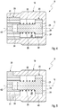
Das Rückschlagventil 9 weist ein Ventilgehäuse 19 und einen entlang einer Ventillängsachse L axial verschieblichen Ventilschließkörper 20 auf, welcher mittels einer Ventilfeder 22 gegen einen Ventilsitz 23 vorgespannt ist.The
Der Ventilschließkörper 20 ist in dem Ventilgehäuse 19 geführt vorgesehen und weist einen dornförmigen Führungskörper 25 auf, welcher die Ventilfeder 22 in ihrer gesamten Länge durchragt, so dass diese geführt ist. Dabei ist der dornförmige Führungskörper 25 mit dem Ventilschließkörper 20 bewegbar ausgebildet und in das Ventilgehäuse 19 oder einem in dem Ventilgehäuse 19 angeordneten Deckel 35 eintauchbar vorgesehen.The
Wie den
Wie in
Der Ventilschließkörper 20 kann an seiner Außenseite Vertiefungen bzw. Ausnehmungen 40 (
Gemäß
Der Deckel 35 weist Öffnungen 41 zum Durchfluss der Hydraulikflüssigkeit in Richtung Hydraulikkammer 4 (
Der erfindungsgemäße verbesserte Aufbau der Rückschlagventile 9, 10 erlaubt eine Führung der Ventilfeder 22 über die ganze Länge, so dass kein Zwischenraum entstehen kann, in welchen die Ventilfeder 22 bei Querkräften hineingeraten und somit zerstört werden kann.The improved construction of the
Ferner ist bei der beschriebenen Ausführung des Ventilschließkörpers 20 als vorteilhaft anzusehen, dass auf Radialbohrungen im Ventilgehäuse 19 verzichtet werden kann, da dieses vorzugsweise in das Pleuel 1 eingeschraubt vorgesehen ist. Durch den Führungskörper 25 kann die Führung des Ventilschließkörpers 20 verbessert werden.Furthermore, in the described embodiment of the
Claims (16)
Applications Claiming Priority (3)
| Application Number | Priority Date | Filing Date | Title |
|---|---|---|---|
| DE102015120443 | 2015-11-25 | ||
| DE102015120359 | 2015-11-25 | ||
| DE102016110279.2A DE102016110279A1 (en) | 2015-11-25 | 2016-06-03 | Check valve for a connecting rod for variable compression of an internal combustion engine and connecting rod with such a check valve |
Publications (2)
| Publication Number | Publication Date |
|---|---|
| EP3173601A1 true EP3173601A1 (en) | 2017-05-31 |
| EP3173601B1 EP3173601B1 (en) | 2018-03-14 |
Family
ID=57406055
Family Applications (1)
| Application Number | Title | Priority Date | Filing Date |
|---|---|---|---|
| EP16199578.2A Not-in-force EP3173601B1 (en) | 2015-11-25 | 2016-11-18 | Non-return valve for a connecting rod for a variable compression of an internal combustion engine, and connecting rod with such a non-return valve |
Country Status (1)
| Country | Link |
|---|---|
| EP (1) | EP3173601B1 (en) |
Citations (4)
| Publication number | Priority date | Publication date | Assignee | Title |
|---|---|---|---|---|
| DE102007018068A1 (en) * | 2006-12-14 | 2008-06-19 | Hyundai Motor Company | Check valve of a cylinder head |
| DE102007016625A1 (en) * | 2007-04-05 | 2008-10-09 | Continental Automotive Gmbh | Valve and injection system for an internal combustion engine with valve |
| DE102012112481A1 (en) | 2012-12-18 | 2014-06-18 | Dr. Ing. H.C. F. Porsche Aktiengesellschaft | Check valve for connecting rod of engine, has valve closing body, which is movable to and fro for showing valve seat along valve longitudinal axis, where radial inlet-or flow direction is provided in relation to valve longitudinal axis |
| EP2821619A1 (en) * | 2013-07-05 | 2015-01-07 | Hilite Germany GmbH | Connecting rod for a two-stage variable compression |
-
2016
- 2016-11-18 EP EP16199578.2A patent/EP3173601B1/en not_active Not-in-force
Patent Citations (5)
| Publication number | Priority date | Publication date | Assignee | Title |
|---|---|---|---|---|
| DE102007018068A1 (en) * | 2006-12-14 | 2008-06-19 | Hyundai Motor Company | Check valve of a cylinder head |
| DE102007016625A1 (en) * | 2007-04-05 | 2008-10-09 | Continental Automotive Gmbh | Valve and injection system for an internal combustion engine with valve |
| DE102012112481A1 (en) | 2012-12-18 | 2014-06-18 | Dr. Ing. H.C. F. Porsche Aktiengesellschaft | Check valve for connecting rod of engine, has valve closing body, which is movable to and fro for showing valve seat along valve longitudinal axis, where radial inlet-or flow direction is provided in relation to valve longitudinal axis |
| EP2821619A1 (en) * | 2013-07-05 | 2015-01-07 | Hilite Germany GmbH | Connecting rod for a two-stage variable compression |
| DE102013107127A1 (en) | 2013-07-05 | 2015-01-08 | Hilite Germany Gmbh | Connecting rod for a two-stage variable compression |
Also Published As
| Publication number | Publication date |
|---|---|
| EP3173601B1 (en) | 2018-03-14 |
Similar Documents
| Publication | Publication Date | Title |
|---|---|---|
| DE102014106715A1 (en) | Changeover valve and internal combustion engine | |
| DE102012112461A1 (en) | Reversing valve for controlling engine oil of internal combustion engine i.e. petrol engine, in motor car, has groove connecting first and second hydraulic fluid lines to vent channel in first and second switch positions, respectively | |
| DE102013021065A1 (en) | Piston machine with support piston | |
| DE102010061360A1 (en) | Reversing valve for controlling engine oil flow in spark ignition petrol engine of passenger motor car, has two working chambers brought in fluid communication with engine inner space via fluid conduits | |
| DE102016008306A1 (en) | Connecting rod with adjustable connecting rod length | |
| DE102015110664A1 (en) | Changeover valve and internal combustion engine | |
| WO2017162425A1 (en) | Non-return valve for a connecting rod for an internal combustion engine with variable compression and connecting rod having a non-return valve | |
| DE102016110279A1 (en) | Check valve for a connecting rod for variable compression of an internal combustion engine and connecting rod with such a check valve | |
| DE102017121443A1 (en) | Check valve for a connecting rod of an internal combustion engine with variable compression and connecting rod with such a check valve | |
| WO2018083256A1 (en) | Adjustable-length connecting rod having a piston/cylinder unit having cylinder sleeve | |
| DE102010061359A1 (en) | Switching valve for controlling fluid flow in combustion engine of vehicle, comprises switching unit, which is adapted to shift switching valve into primary switching position and secondary switching position | |
| AT519156A1 (en) | Length adjustable connecting rod for a reciprocating engine, reciprocating engine and vehicle | |
| DE102015110663A1 (en) | internal combustion engine | |
| EP3404232B1 (en) | Connecting rod for a combustion engine with variable compression | |
| EP3173601B1 (en) | Non-return valve for a connecting rod for a variable compression of an internal combustion engine, and connecting rod with such a non-return valve | |
| DE102015210597A1 (en) | Reciprocating engine and motor vehicle | |
| DE102018118449A1 (en) | Check valve for a connecting rod of an internal combustion engine with variable compression and connecting rod with a check valve | |
| DE102017113250A1 (en) | Piston for a connecting rod and connecting rod | |
| DE102017107719A1 (en) | Hydraulic valve for adjusting a hydraulic fluid flow of a connecting rod for a variable compression internal combustion engine | |
| DE102017107682A1 (en) | Connecting rod for a variable compression internal combustion engine | |
| DE102016120943A1 (en) | Connecting rod with adjusting mechanism between connecting rod and piston rod | |
| DE102016117874A1 (en) | Changeover valve for controlling a hydraulic fluid flow and connecting rod with a changeover valve | |
| EP3361069B1 (en) | Connecting rod of a combustion engine with variable compression with a check valve | |
| DE102016104958A1 (en) | Check valve for a connecting rod for a variable compression internal combustion engine and connecting rod with a check valve | |
| DE102015121918A1 (en) | Changeover valve, connecting rod and internal combustion engine |
Legal Events
| Date | Code | Title | Description |
|---|---|---|---|
| PUAI | Public reference made under article 153(3) epc to a published international application that has entered the european phase |
Free format text: ORIGINAL CODE: 0009012 |
|
| AK | Designated contracting states |
Kind code of ref document: A1 Designated state(s): AL AT BE BG CH CY CZ DE DK EE ES FI FR GB GR HR HU IE IS IT LI LT LU LV MC MK MT NL NO PL PT RO RS SE SI SK SM TR |
|
| AX | Request for extension of the european patent |
Extension state: BA ME |
|
| 17P | Request for examination filed |
Effective date: 20170502 |
|
| GRAP | Despatch of communication of intention to grant a patent |
Free format text: ORIGINAL CODE: EPIDOSNIGR1 |
|
| RIC1 | Information provided on ipc code assigned before grant |
Ipc: F16K 15/02 20060101ALN20170718BHEP Ipc: F02B 75/04 20060101AFI20170718BHEP |
|
| GRAS | Grant fee paid |
Free format text: ORIGINAL CODE: EPIDOSNIGR3 |
|
| INTG | Intention to grant announced |
Effective date: 20170823 |
|
| GRAA | (expected) grant |
Free format text: ORIGINAL CODE: 0009210 |
|
| RBV | Designated contracting states (corrected) |
Designated state(s): AL AT BE BG CH CY CZ DE DK EE ES FI FR GB GR HR HU IE IS IT LI LT LU LV MC MK MT NL NO PL PT RO RS SE SI SK SM TR |
|
| AK | Designated contracting states |
Kind code of ref document: B1 Designated state(s): AL AT BE BG CH CY CZ DE DK EE ES FI FR GB GR HR HU IE IS IT LI LT LU LV MC MK MT NL NO PL PT RO RS SE SI SK SM TR |
|
| REG | Reference to a national code |
Ref country code: GB Ref legal event code: FG4D Free format text: NOT ENGLISH |
|
| REG | Reference to a national code |
Ref country code: CH Ref legal event code: EP Ref country code: AT Ref legal event code: REF Ref document number: 979117 Country of ref document: AT Kind code of ref document: T Effective date: 20180315 |
|
| REG | Reference to a national code |
Ref country code: IE Ref legal event code: FG4D Free format text: LANGUAGE OF EP DOCUMENT: GERMAN |
|
| REG | Reference to a national code |
Ref country code: DE Ref legal event code: R096 Ref document number: 502016000718 Country of ref document: DE |
|
| REG | Reference to a national code |
Ref country code: NL Ref legal event code: MP Effective date: 20180314 |
|
| REG | Reference to a national code |
Ref country code: LT Ref legal event code: MG4D |
|
| PG25 | Lapsed in a contracting state [announced via postgrant information from national office to epo] |
Ref country code: LT Free format text: LAPSE BECAUSE OF FAILURE TO SUBMIT A TRANSLATION OF THE DESCRIPTION OR TO PAY THE FEE WITHIN THE PRESCRIBED TIME-LIMIT Effective date: 20180314 Ref country code: CY Free format text: LAPSE BECAUSE OF FAILURE TO SUBMIT A TRANSLATION OF THE DESCRIPTION OR TO PAY THE FEE WITHIN THE PRESCRIBED TIME-LIMIT Effective date: 20180314 Ref country code: HR Free format text: LAPSE BECAUSE OF FAILURE TO SUBMIT A TRANSLATION OF THE DESCRIPTION OR TO PAY THE FEE WITHIN THE PRESCRIBED TIME-LIMIT Effective date: 20180314 Ref country code: FI Free format text: LAPSE BECAUSE OF FAILURE TO SUBMIT A TRANSLATION OF THE DESCRIPTION OR TO PAY THE FEE WITHIN THE PRESCRIBED TIME-LIMIT Effective date: 20180314 Ref country code: NO Free format text: LAPSE BECAUSE OF FAILURE TO SUBMIT A TRANSLATION OF THE DESCRIPTION OR TO PAY THE FEE WITHIN THE PRESCRIBED TIME-LIMIT Effective date: 20180614 |
|
| PG25 | Lapsed in a contracting state [announced via postgrant information from national office to epo] |
Ref country code: RS Free format text: LAPSE BECAUSE OF FAILURE TO SUBMIT A TRANSLATION OF THE DESCRIPTION OR TO PAY THE FEE WITHIN THE PRESCRIBED TIME-LIMIT Effective date: 20180314 Ref country code: SE Free format text: LAPSE BECAUSE OF FAILURE TO SUBMIT A TRANSLATION OF THE DESCRIPTION OR TO PAY THE FEE WITHIN THE PRESCRIBED TIME-LIMIT Effective date: 20180314 Ref country code: LV Free format text: LAPSE BECAUSE OF FAILURE TO SUBMIT A TRANSLATION OF THE DESCRIPTION OR TO PAY THE FEE WITHIN THE PRESCRIBED TIME-LIMIT Effective date: 20180314 Ref country code: GR Free format text: LAPSE BECAUSE OF FAILURE TO SUBMIT A TRANSLATION OF THE DESCRIPTION OR TO PAY THE FEE WITHIN THE PRESCRIBED TIME-LIMIT Effective date: 20180615 Ref country code: BG Free format text: LAPSE BECAUSE OF FAILURE TO SUBMIT A TRANSLATION OF THE DESCRIPTION OR TO PAY THE FEE WITHIN THE PRESCRIBED TIME-LIMIT Effective date: 20180614 |
|
| PG25 | Lapsed in a contracting state [announced via postgrant information from national office to epo] |
Ref country code: MT Free format text: LAPSE BECAUSE OF FAILURE TO SUBMIT A TRANSLATION OF THE DESCRIPTION OR TO PAY THE FEE WITHIN THE PRESCRIBED TIME-LIMIT Effective date: 20180314 |
|
| PG25 | Lapsed in a contracting state [announced via postgrant information from national office to epo] |
Ref country code: AL Free format text: LAPSE BECAUSE OF FAILURE TO SUBMIT A TRANSLATION OF THE DESCRIPTION OR TO PAY THE FEE WITHIN THE PRESCRIBED TIME-LIMIT Effective date: 20180314 Ref country code: ES Free format text: LAPSE BECAUSE OF FAILURE TO SUBMIT A TRANSLATION OF THE DESCRIPTION OR TO PAY THE FEE WITHIN THE PRESCRIBED TIME-LIMIT Effective date: 20180314 Ref country code: RO Free format text: LAPSE BECAUSE OF FAILURE TO SUBMIT A TRANSLATION OF THE DESCRIPTION OR TO PAY THE FEE WITHIN THE PRESCRIBED TIME-LIMIT Effective date: 20180314 Ref country code: NL Free format text: LAPSE BECAUSE OF FAILURE TO SUBMIT A TRANSLATION OF THE DESCRIPTION OR TO PAY THE FEE WITHIN THE PRESCRIBED TIME-LIMIT Effective date: 20180314 Ref country code: EE Free format text: LAPSE BECAUSE OF FAILURE TO SUBMIT A TRANSLATION OF THE DESCRIPTION OR TO PAY THE FEE WITHIN THE PRESCRIBED TIME-LIMIT Effective date: 20180314 Ref country code: IT Free format text: LAPSE BECAUSE OF FAILURE TO SUBMIT A TRANSLATION OF THE DESCRIPTION OR TO PAY THE FEE WITHIN THE PRESCRIBED TIME-LIMIT Effective date: 20180314 Ref country code: PL Free format text: LAPSE BECAUSE OF FAILURE TO SUBMIT A TRANSLATION OF THE DESCRIPTION OR TO PAY THE FEE WITHIN THE PRESCRIBED TIME-LIMIT Effective date: 20180314 |
|
| PG25 | Lapsed in a contracting state [announced via postgrant information from national office to epo] |
Ref country code: SK Free format text: LAPSE BECAUSE OF FAILURE TO SUBMIT A TRANSLATION OF THE DESCRIPTION OR TO PAY THE FEE WITHIN THE PRESCRIBED TIME-LIMIT Effective date: 20180314 Ref country code: CZ Free format text: LAPSE BECAUSE OF FAILURE TO SUBMIT A TRANSLATION OF THE DESCRIPTION OR TO PAY THE FEE WITHIN THE PRESCRIBED TIME-LIMIT Effective date: 20180314 Ref country code: SM Free format text: LAPSE BECAUSE OF FAILURE TO SUBMIT A TRANSLATION OF THE DESCRIPTION OR TO PAY THE FEE WITHIN THE PRESCRIBED TIME-LIMIT Effective date: 20180314 |
|
| REG | Reference to a national code |
Ref country code: DE Ref legal event code: R097 Ref document number: 502016000718 Country of ref document: DE |
|
| PG25 | Lapsed in a contracting state [announced via postgrant information from national office to epo] |
Ref country code: PT Free format text: LAPSE BECAUSE OF FAILURE TO SUBMIT A TRANSLATION OF THE DESCRIPTION OR TO PAY THE FEE WITHIN THE PRESCRIBED TIME-LIMIT Effective date: 20180716 |
|
| PLBE | No opposition filed within time limit |
Free format text: ORIGINAL CODE: 0009261 |
|
| STAA | Information on the status of an ep patent application or granted ep patent |
Free format text: STATUS: NO OPPOSITION FILED WITHIN TIME LIMIT |
|
| PG25 | Lapsed in a contracting state [announced via postgrant information from national office to epo] |
Ref country code: DK Free format text: LAPSE BECAUSE OF FAILURE TO SUBMIT A TRANSLATION OF THE DESCRIPTION OR TO PAY THE FEE WITHIN THE PRESCRIBED TIME-LIMIT Effective date: 20180314 |
|
| 26N | No opposition filed |
Effective date: 20181217 |
|
| PG25 | Lapsed in a contracting state [announced via postgrant information from national office to epo] |
Ref country code: MC Free format text: LAPSE BECAUSE OF FAILURE TO SUBMIT A TRANSLATION OF THE DESCRIPTION OR TO PAY THE FEE WITHIN THE PRESCRIBED TIME-LIMIT Effective date: 20180314 Ref country code: LU Free format text: LAPSE BECAUSE OF NON-PAYMENT OF DUE FEES Effective date: 20181118 |
|
| REG | Reference to a national code |
Ref country code: BE Ref legal event code: MM Effective date: 20181130 |
|
| REG | Reference to a national code |
Ref country code: IE Ref legal event code: MM4A |
|
| PG25 | Lapsed in a contracting state [announced via postgrant information from national office to epo] |
Ref country code: IE Free format text: LAPSE BECAUSE OF NON-PAYMENT OF DUE FEES Effective date: 20181118 |
|
| PG25 | Lapsed in a contracting state [announced via postgrant information from national office to epo] |
Ref country code: BE Free format text: LAPSE BECAUSE OF NON-PAYMENT OF DUE FEES Effective date: 20181130 |
|
| PGFP | Annual fee paid to national office [announced via postgrant information from national office to epo] |
Ref country code: FR Payment date: 20191120 Year of fee payment: 4 |
|
| PG25 | Lapsed in a contracting state [announced via postgrant information from national office to epo] |
Ref country code: TR Free format text: LAPSE BECAUSE OF FAILURE TO SUBMIT A TRANSLATION OF THE DESCRIPTION OR TO PAY THE FEE WITHIN THE PRESCRIBED TIME-LIMIT Effective date: 20180314 |
|
| PG25 | Lapsed in a contracting state [announced via postgrant information from national office to epo] |
Ref country code: HU Free format text: LAPSE BECAUSE OF FAILURE TO SUBMIT A TRANSLATION OF THE DESCRIPTION OR TO PAY THE FEE WITHIN THE PRESCRIBED TIME-LIMIT; INVALID AB INITIO Effective date: 20161118 Ref country code: MK Free format text: LAPSE BECAUSE OF NON-PAYMENT OF DUE FEES Effective date: 20180314 |
|
| REG | Reference to a national code |
Ref country code: CH Ref legal event code: PL |
|
| PG25 | Lapsed in a contracting state [announced via postgrant information from national office to epo] |
Ref country code: LI Free format text: LAPSE BECAUSE OF NON-PAYMENT OF DUE FEES Effective date: 20191130 Ref country code: CH Free format text: LAPSE BECAUSE OF NON-PAYMENT OF DUE FEES Effective date: 20191130 Ref country code: IS Free format text: LAPSE BECAUSE OF FAILURE TO SUBMIT A TRANSLATION OF THE DESCRIPTION OR TO PAY THE FEE WITHIN THE PRESCRIBED TIME-LIMIT Effective date: 20180714 |
|
| PG25 | Lapsed in a contracting state [announced via postgrant information from national office to epo] |
Ref country code: SI Free format text: LAPSE BECAUSE OF NON-PAYMENT OF DUE FEES Effective date: 20181118 |
|
| GBPC | Gb: european patent ceased through non-payment of renewal fee |
Effective date: 20201118 |
|
| PG25 | Lapsed in a contracting state [announced via postgrant information from national office to epo] |
Ref country code: FR Free format text: LAPSE BECAUSE OF NON-PAYMENT OF DUE FEES Effective date: 20201130 |
|
| PG25 | Lapsed in a contracting state [announced via postgrant information from national office to epo] |
Ref country code: GB Free format text: LAPSE BECAUSE OF NON-PAYMENT OF DUE FEES Effective date: 20201118 |
|
| PGFP | Annual fee paid to national office [announced via postgrant information from national office to epo] |
Ref country code: DE Payment date: 20211118 Year of fee payment: 6 |
|
| REG | Reference to a national code |
Ref country code: AT Ref legal event code: MM01 Ref document number: 979117 Country of ref document: AT Kind code of ref document: T Effective date: 20211118 |
|
| PG25 | Lapsed in a contracting state [announced via postgrant information from national office to epo] |
Ref country code: AT Free format text: LAPSE BECAUSE OF NON-PAYMENT OF DUE FEES Effective date: 20211118 |
|
| REG | Reference to a national code |
Ref country code: DE Ref legal event code: R119 Ref document number: 502016000718 Country of ref document: DE |
|
| PG25 | Lapsed in a contracting state [announced via postgrant information from national office to epo] |
Ref country code: DE Free format text: LAPSE BECAUSE OF NON-PAYMENT OF DUE FEES Effective date: 20230601 |