EP3173598A1 - Motorsystem mit einem abgasrückführungskreislauf - Google Patents
Motorsystem mit einem abgasrückführungskreislauf Download PDFInfo
- Publication number
- EP3173598A1 EP3173598A1 EP16201414.6A EP16201414A EP3173598A1 EP 3173598 A1 EP3173598 A1 EP 3173598A1 EP 16201414 A EP16201414 A EP 16201414A EP 3173598 A1 EP3173598 A1 EP 3173598A1
- Authority
- EP
- European Patent Office
- Prior art keywords
- turbine
- turbocharger
- energy recovery
- circuit
- engine
- Prior art date
- Legal status (The legal status is an assumption and is not a legal conclusion. Google has not performed a legal analysis and makes no representation as to the accuracy of the status listed.)
- Withdrawn
Links
- 239000007789 gas Substances 0.000 title claims abstract description 28
- 230000003134 recirculating effect Effects 0.000 title claims 2
- 238000011084 recovery Methods 0.000 claims abstract description 39
- 230000006835 compression Effects 0.000 claims description 4
- 238000007906 compression Methods 0.000 claims description 4
- 230000008878 coupling Effects 0.000 claims description 4
- 238000010168 coupling process Methods 0.000 claims description 4
- 238000005859 coupling reaction Methods 0.000 claims description 4
- MWUXSHHQAYIFBG-UHFFFAOYSA-N Nitric oxide Chemical compound O=[N] MWUXSHHQAYIFBG-UHFFFAOYSA-N 0.000 description 6
- 239000000446 fuel Substances 0.000 description 4
- 238000002485 combustion reaction Methods 0.000 description 3
- 239000003546 flue gas Substances 0.000 description 3
- 238000011144 upstream manufacturing Methods 0.000 description 3
- 230000001133 acceleration Effects 0.000 description 2
- UGFAIRIUMAVXCW-UHFFFAOYSA-N Carbon monoxide Chemical compound [O+]#[C-] UGFAIRIUMAVXCW-UHFFFAOYSA-N 0.000 description 1
- 238000001816 cooling Methods 0.000 description 1
Images

Classifications
-
- F—MECHANICAL ENGINEERING; LIGHTING; HEATING; WEAPONS; BLASTING
- F02—COMBUSTION ENGINES; HOT-GAS OR COMBUSTION-PRODUCT ENGINE PLANTS
- F02B—INTERNAL-COMBUSTION PISTON ENGINES; COMBUSTION ENGINES IN GENERAL
- F02B37/00—Engines characterised by provision of pumps driven at least for part of the time by exhaust
- F02B37/004—Engines characterised by provision of pumps driven at least for part of the time by exhaust with exhaust drives arranged in series
-
- F—MECHANICAL ENGINEERING; LIGHTING; HEATING; WEAPONS; BLASTING
- F01—MACHINES OR ENGINES IN GENERAL; ENGINE PLANTS IN GENERAL; STEAM ENGINES
- F01N—GAS-FLOW SILENCERS OR EXHAUST APPARATUS FOR MACHINES OR ENGINES IN GENERAL; GAS-FLOW SILENCERS OR EXHAUST APPARATUS FOR INTERNAL COMBUSTION ENGINES
- F01N5/00—Exhaust or silencing apparatus combined or associated with devices profiting by exhaust energy
- F01N5/04—Exhaust or silencing apparatus combined or associated with devices profiting by exhaust energy the devices using kinetic energy
-
- F—MECHANICAL ENGINEERING; LIGHTING; HEATING; WEAPONS; BLASTING
- F02—COMBUSTION ENGINES; HOT-GAS OR COMBUSTION-PRODUCT ENGINE PLANTS
- F02M—SUPPLYING COMBUSTION ENGINES IN GENERAL WITH COMBUSTIBLE MIXTURES OR CONSTITUENTS THEREOF
- F02M26/00—Engine-pertinent apparatus for adding exhaust gases to combustion-air, main fuel or fuel-air mixture, e.g. by exhaust gas recirculation [EGR] systems
- F02M26/02—EGR systems specially adapted for supercharged engines
- F02M26/04—EGR systems specially adapted for supercharged engines with a single turbocharger
- F02M26/06—Low pressure loops, i.e. wherein recirculated exhaust gas is taken out from the exhaust downstream of the turbocharger turbine and reintroduced into the intake system upstream of the compressor
-
- Y—GENERAL TAGGING OF NEW TECHNOLOGICAL DEVELOPMENTS; GENERAL TAGGING OF CROSS-SECTIONAL TECHNOLOGIES SPANNING OVER SEVERAL SECTIONS OF THE IPC; TECHNICAL SUBJECTS COVERED BY FORMER USPC CROSS-REFERENCE ART COLLECTIONS [XRACs] AND DIGESTS
- Y02—TECHNOLOGIES OR APPLICATIONS FOR MITIGATION OR ADAPTATION AGAINST CLIMATE CHANGE
- Y02T—CLIMATE CHANGE MITIGATION TECHNOLOGIES RELATED TO TRANSPORTATION
- Y02T10/00—Road transport of goods or passengers
- Y02T10/10—Internal combustion engine [ICE] based vehicles
- Y02T10/12—Improving ICE efficiencies
Definitions
- the present invention relates to thermal machines and more particularly to internal combustion engines with a flue gas recirculation circuit and turbocharger.
- turbochargers to increase the pressure of the admitted gases.
- These turbochargers comprise an air compressor driven by a turbine driven by the pressure of the exhaust gas.
- the invention is more particularly concerned with engine systems with recirculation of low pressure exhaust gases, in which a fraction of the exhaust gases taken downstream of the turbine of the turbocharger is mixed with the admitted gases, after passing through a EGR exhaust gas recirculation valve or EGR valve (for exhaust gas recirculation according to the English terminology) EGR creating a pressure drop, the non-recirculated gases being evacuated via an exhaust pressure valve or CPE valve.
- EGR exhaust gas recirculation valve or EGR valve for exhaust gas recirculation according to the English terminology
- the present invention therefore aims to overcome one or more of the disadvantages of the devices of the prior art by providing an engine assembly to reduce the exhaust pressure and thus the fuel consumption.
- the present invention proposes a motor system with a low-pressure recirculation circuit for burnt gases, comprising a heat engine equipped with an exhaust circuit disposed at the output of the heat engine, a turbocharger comprising a turbocharger turbine arranged on the fuel circuit.
- exhaust system in which the recirculation circuit is associated with a system of energy recovery receiving the low pressure exhaust gas downstream of the turbocharger, the energy recovery system being coupled to the turbine of the turbocharger.
- the energy recovery turbine makes it possible to recover the enthalpy normally lost in the recirculation circuit.
- the energy recovery system is a turbine.
- the turbocharger turbine and the energy recovery system are coupled in rotation.
- the coupling between the turbocharger turbine and the energy recovery system is achieved by a rigid connection.
- the system comprises a decoupling system of the energy recovery system.
- the decoupling system is a clutch.
- the decoupling system is a free wheel.
- the system comprises a valve downstream of the turbine.
- the heat engine is a compression ignition engine or controlled.
- the invention also relates to a vehicle, in particular an automobile, equipped with a motor system as defined according to the invention.
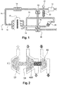
- the architecture represented in figure 1 also called engine system 10, comprises according to one embodiment, an internal combustion engine 17 with compression ignition or controlled, for example diesel or gasoline or other, connected to a circuit 11 for admission of air into the engine , comprising an inlet air filter 12, a compressor 13 for compressing the air for the engine and a cooler 14 downstream of the compressor 13, for cooling the charge air.
- an internal combustion engine 17 with compression ignition or controlled for example diesel or gasoline or other
- a circuit 11 for admission of air into the engine comprising an inlet air filter 12, a compressor 13 for compressing the air for the engine and a cooler 14 downstream of the compressor 13, for cooling the charge air.
- a flow control device 16 such as for example a butterfly valve, makes it possible to control the flow of air admitted into the internal combustion engine 17.
- the latter is connected to a circuit exhaust system 18 which comprises a turbocharger turbine 19, driven by the exhaust gas, coupled to the supercharger compressor 13 to drive it in rotation.
- the exhaust circuit 18 also comprises, downstream of the turbine 19, a device 20 for treating the flue gases.
- EGR exhaust gas recirculation valve or EGR valve exhaust gas recirculation according to the English terminology
- the recirculation circuit 21 is associated with a system 30 of energy recovery coupled to the turbine 19 of the turbocharger.
- this energy recovery system 30 is a turbine 30 for energy recovery, or any other equivalent means.
- This energy recovery turbine 30 is on an energy recovery circuit 24 which is formed downstream of the source of the recirculation circuit 21. exhaust gases.
- the energy recovery circuit 24 also allows the evacuation of the exhaust gases.
- the energy recovery turbine and the energy recovery circuit form the energy recovery system.
- the energy recovery turbine 30 makes it possible to recover the enthalpy normally lost in the recirculation circuit 21 by the pressure drop in the valve CPE.
- the power required to drive the compressor remains virtually unchanged, as well as the flow rate and temperature of the gas passing through the turbine of the turbocharger, the power supply on the turbocharger shaft allows to reduce the expansion ratio at the level of turbocharger turbine, so the exhaust pressure. As a result, the pumped losses are reduced and thus the fuel consumption of the engine.
- the gain provided by the energy recovery system in fuel consumption is illustrated on the figure 3 for a diesel vehicle with a steady speed of 130km / h.
- the coupling between the turbine 19 of the turbocharger and the turbine 30 of energy recovery is achieved by a rigid connection 400 illustrated figure 2 .
- the assembly comprises a system making it possible to decouple the energy recovery turbine 30, for example, during the operating phases requiring a rapid increase in the speed of rotation of the turbocharger, and by example a strong acceleration.
- the decoupling system is a clutch. Specifically, in normal operation with recovery, the clutch is closed, ensuring the connection between the two turbines, so the assistance of the turbocharger. For example, for the revving of the turbocharger, the clutch is open, in order to limit the inertia to accelerate. This solution offers great freedom in terms of system control.
- the decoupling system is a free wheel.
- the recovery turbine In the operating phases where the recovery turbine is of interest, it is driven by the exhaust gas and freewheel is blocked, ensuring the assistance of the turbocharger.
- the assistance is maintained automatically as the power recovered at the additional turbine tends to give it an acceleration greater than that of the turbocharger.
- the freewheel allows the recovery turbine to turn freely, which prevents its inertia from slowing down the speed increase of the turbocharger. This system self-regulates and does not require additional actuator.
- the proposed solution with a decoupling system ensures not only that the response time of the air loop is not greater than the reference case, but can even, in some operating phases, participate in its reduction.
- the recovery turbine contributes to the recovery of the turbocharger.
- the invention applies to a land vehicle, naval or air motor, as well as to generator engines and all other applications using a turbocharged heat engine and low-pressure recirculation of flue gases.
Landscapes
- Engineering & Computer Science (AREA)
- Chemical & Material Sciences (AREA)
- Combustion & Propulsion (AREA)
- Mechanical Engineering (AREA)
- General Engineering & Computer Science (AREA)
- Supercharger (AREA)
- Exhaust-Gas Circulating Devices (AREA)
Applications Claiming Priority (1)
| Application Number | Priority Date | Filing Date | Title |
|---|---|---|---|
| FR1561541A FR3044363B1 (fr) | 2015-11-30 | 2015-11-30 | Systeme moteur avec circuit de recirculation des gaz brules |
Publications (1)
| Publication Number | Publication Date |
|---|---|
| EP3173598A1 true EP3173598A1 (de) | 2017-05-31 |
Family
ID=57286534
Family Applications (1)
| Application Number | Title | Priority Date | Filing Date |
|---|---|---|---|
| EP16201414.6A Withdrawn EP3173598A1 (de) | 2015-11-30 | 2016-11-30 | Motorsystem mit einem abgasrückführungskreislauf |
Country Status (2)
| Country | Link |
|---|---|
| EP (1) | EP3173598A1 (de) |
| FR (1) | FR3044363B1 (de) |
Citations (8)
| Publication number | Priority date | Publication date | Assignee | Title |
|---|---|---|---|---|
| JP2005069092A (ja) * | 2003-08-25 | 2005-03-17 | Nissan Diesel Motor Co Ltd | ターボコンパウンドエンジンの排気還流装置 |
| EP1903197A2 (de) * | 2006-07-27 | 2008-03-26 | Iveco S.p.A. | Motor mit Energierückgewinnungs- und Katalysatorabgas-Behandlungsverfahren |
| US20090205326A1 (en) * | 2008-02-14 | 2009-08-20 | Dresser, Inc. | Recirculation of Exhaust Gas Condensate |
| DE102011108204A1 (de) * | 2011-07-20 | 2013-01-24 | Daimler Ag | Verbrennungskraftmaschine, insbesondere für einen Kraftwagen |
| FR3005996A1 (fr) * | 2013-05-21 | 2014-11-28 | Peugeot Citroen Automobiles Sa | Dispositif pour une recirculation homogeneisee de gaz d'echappement |
| WO2015086935A1 (fr) * | 2013-12-13 | 2015-06-18 | Renault S.A.S. | Ligne d'échappement de moteur à combustion interne et moteur à combustion interne comportant une telle ligne d'échappement |
| WO2015197993A1 (fr) * | 2014-06-26 | 2015-12-30 | Valeo Systemes De Controle Moteur | Système moteur avec circuit de recirculation des gaz brûlés |
| WO2015197994A1 (fr) * | 2014-06-26 | 2015-12-30 | Valeo Systemes De Controle Moteur | Système moteur avec circuit de recirculation basse pression des gaz brûles |
-
2015
- 2015-11-30 FR FR1561541A patent/FR3044363B1/fr active Active
-
2016
- 2016-11-30 EP EP16201414.6A patent/EP3173598A1/de not_active Withdrawn
Patent Citations (8)
| Publication number | Priority date | Publication date | Assignee | Title |
|---|---|---|---|---|
| JP2005069092A (ja) * | 2003-08-25 | 2005-03-17 | Nissan Diesel Motor Co Ltd | ターボコンパウンドエンジンの排気還流装置 |
| EP1903197A2 (de) * | 2006-07-27 | 2008-03-26 | Iveco S.p.A. | Motor mit Energierückgewinnungs- und Katalysatorabgas-Behandlungsverfahren |
| US20090205326A1 (en) * | 2008-02-14 | 2009-08-20 | Dresser, Inc. | Recirculation of Exhaust Gas Condensate |
| DE102011108204A1 (de) * | 2011-07-20 | 2013-01-24 | Daimler Ag | Verbrennungskraftmaschine, insbesondere für einen Kraftwagen |
| FR3005996A1 (fr) * | 2013-05-21 | 2014-11-28 | Peugeot Citroen Automobiles Sa | Dispositif pour une recirculation homogeneisee de gaz d'echappement |
| WO2015086935A1 (fr) * | 2013-12-13 | 2015-06-18 | Renault S.A.S. | Ligne d'échappement de moteur à combustion interne et moteur à combustion interne comportant une telle ligne d'échappement |
| WO2015197993A1 (fr) * | 2014-06-26 | 2015-12-30 | Valeo Systemes De Controle Moteur | Système moteur avec circuit de recirculation des gaz brûlés |
| WO2015197994A1 (fr) * | 2014-06-26 | 2015-12-30 | Valeo Systemes De Controle Moteur | Système moteur avec circuit de recirculation basse pression des gaz brûles |
Also Published As
| Publication number | Publication date |
|---|---|
| FR3044363A1 (fr) | 2017-06-02 |
| FR3044363B1 (fr) | 2019-08-30 |
Similar Documents
| Publication | Publication Date | Title |
|---|---|---|
| EP3161289B1 (de) | Motorsystem mit abgasrückführkreis | |
| EP1771649B1 (de) | Vorrichtung und verfahren zur aufladung eines ansaugrohres eines turboaufgeladenen motors mit druckluft | |
| FR3046434A1 (fr) | Un systeme de turbine de puissance a double conduit d'ecoulement et son procede de controle | |
| EP3092382B1 (de) | Abgasstrang eines verbrennungsmotors und verbrennungsmotor mit einem solchen abgasstrang | |
| CN107725176B (zh) | 具有双废气门阀的涡轮增压器 | |
| WO2018083400A1 (fr) | Système d'injection d'air dans un circuit d'échappement de gaz d'un moteur thermique suralimenté | |
| EP3173597B1 (de) | Motorsystem mit einem abgasrückführungssystem | |
| EP3161290B1 (de) | Motorsystem mit niederdruck-abgasrückführung | |
| FR3044363B1 (fr) | Systeme moteur avec circuit de recirculation des gaz brules | |
| WO2015092292A1 (fr) | Ensemble comprenant un moteur thermique et un compresseur électrique | |
| EP3179070B1 (de) | Motorsystem mit energierückgewinnungssystem | |
| EP3084167A1 (de) | Anordnung mit einer wärmekraftmaschine und einer elektrischen verdichter mit konfiguration zum absorbieren von abgasen | |
| WO2017093661A1 (fr) | Systeme moteur avec systeme de recuperation d'energie et circuit basse pression de recirculation des gaz brules | |
| WO2016151270A1 (fr) | Système moteur avec système de récupération d'énergie | |
| FR2927364A1 (fr) | Moteur a combustion interne suralimente equipe d'un conduit de recirculation d'air et/ou de gaz aerodynamiquement optimise | |
| FR2803628A1 (fr) | Procede et dispositif pour diminuer le temps de reponse a l'acceleration des moteurs thermiques suralimentes | |
| WO2018002561A1 (fr) | Systeme moteur avec circuit de recirculation des gaz brules | |
| FR2904051A1 (fr) | Procede de regeneration d'un filtre a particules | |
| EP4276297A1 (de) | Verfahren zur regelung der partiellen abgasrückführung am einlass eines dieselmotors | |
| FR3133403A1 (fr) | Dispositif de turbomachine a chambres de combustion de configurations differentes et vehicule comprenant un tel dispositif | |
| FR2933740A1 (fr) | Procede de rechauffement de l'air frais d'admission moteur a combustion interne et moteur a combustion interne correspondant | |
| FR3060054A1 (fr) | Procede de recirculation des gaz brules avec un compresseur electrique | |
| FR3058465A1 (fr) | Amenagement de volet a contre flux | |
| FR2889560A1 (fr) | Systeme de controle du fonctionnement de la boucle d'admission d'air dans un moteur de vehicule automobile |
Legal Events
| Date | Code | Title | Description |
|---|---|---|---|
| PUAI | Public reference made under article 153(3) epc to a published international application that has entered the european phase |
Free format text: ORIGINAL CODE: 0009012 |
|
| 17P | Request for examination filed |
Effective date: 20161130 |
|
| AK | Designated contracting states |
Kind code of ref document: A1 Designated state(s): AL AT BE BG CH CY CZ DE DK EE ES FI FR GB GR HR HU IE IS IT LI LT LU LV MC MK MT NL NO PL PT RO RS SE SI SK SM TR |
|
| AX | Request for extension of the european patent |
Extension state: BA ME |
|
| 17Q | First examination report despatched |
Effective date: 20170511 |
|
| GRAP | Despatch of communication of intention to grant a patent |
Free format text: ORIGINAL CODE: EPIDOSNIGR1 |
|
| INTG | Intention to grant announced |
Effective date: 20181017 |
|
| STAA | Information on the status of an ep patent application or granted ep patent |
Free format text: STATUS: THE APPLICATION IS DEEMED TO BE WITHDRAWN |
|
| 18D | Application deemed to be withdrawn |
Effective date: 20190228 |