EP3173598A1 - Motor system with circuit for recirculating exhaust gases - Google Patents
Motor system with circuit for recirculating exhaust gases Download PDFInfo
- Publication number
- EP3173598A1 EP3173598A1 EP16201414.6A EP16201414A EP3173598A1 EP 3173598 A1 EP3173598 A1 EP 3173598A1 EP 16201414 A EP16201414 A EP 16201414A EP 3173598 A1 EP3173598 A1 EP 3173598A1
- Authority
- EP
- European Patent Office
- Prior art keywords
- turbine
- turbocharger
- energy recovery
- circuit
- engine
- Prior art date
- Legal status (The legal status is an assumption and is not a legal conclusion. Google has not performed a legal analysis and makes no representation as to the accuracy of the status listed.)
- Withdrawn
Links
- 239000007789 gas Substances 0.000 title claims abstract description 28
- 230000003134 recirculating effect Effects 0.000 title claims 2
- 238000011084 recovery Methods 0.000 claims abstract description 39
- 230000006835 compression Effects 0.000 claims description 4
- 238000007906 compression Methods 0.000 claims description 4
- 230000008878 coupling Effects 0.000 claims description 4
- 238000010168 coupling process Methods 0.000 claims description 4
- 238000005859 coupling reaction Methods 0.000 claims description 4
- MWUXSHHQAYIFBG-UHFFFAOYSA-N Nitric oxide Chemical compound O=[N] MWUXSHHQAYIFBG-UHFFFAOYSA-N 0.000 description 6
- 239000000446 fuel Substances 0.000 description 4
- 238000002485 combustion reaction Methods 0.000 description 3
- 239000003546 flue gas Substances 0.000 description 3
- 238000011144 upstream manufacturing Methods 0.000 description 3
- 230000001133 acceleration Effects 0.000 description 2
- UGFAIRIUMAVXCW-UHFFFAOYSA-N Carbon monoxide Chemical compound [O+]#[C-] UGFAIRIUMAVXCW-UHFFFAOYSA-N 0.000 description 1
- 238000001816 cooling Methods 0.000 description 1
Images

Classifications
-
- F—MECHANICAL ENGINEERING; LIGHTING; HEATING; WEAPONS; BLASTING
- F02—COMBUSTION ENGINES; HOT-GAS OR COMBUSTION-PRODUCT ENGINE PLANTS
- F02B—INTERNAL-COMBUSTION PISTON ENGINES; COMBUSTION ENGINES IN GENERAL
- F02B37/00—Engines characterised by provision of pumps driven at least for part of the time by exhaust
- F02B37/004—Engines characterised by provision of pumps driven at least for part of the time by exhaust with exhaust drives arranged in series
-
- F—MECHANICAL ENGINEERING; LIGHTING; HEATING; WEAPONS; BLASTING
- F01—MACHINES OR ENGINES IN GENERAL; ENGINE PLANTS IN GENERAL; STEAM ENGINES
- F01N—GAS-FLOW SILENCERS OR EXHAUST APPARATUS FOR MACHINES OR ENGINES IN GENERAL; GAS-FLOW SILENCERS OR EXHAUST APPARATUS FOR INTERNAL COMBUSTION ENGINES
- F01N5/00—Exhaust or silencing apparatus combined or associated with devices profiting by exhaust energy
- F01N5/04—Exhaust or silencing apparatus combined or associated with devices profiting by exhaust energy the devices using kinetic energy
-
- F—MECHANICAL ENGINEERING; LIGHTING; HEATING; WEAPONS; BLASTING
- F02—COMBUSTION ENGINES; HOT-GAS OR COMBUSTION-PRODUCT ENGINE PLANTS
- F02M—SUPPLYING COMBUSTION ENGINES IN GENERAL WITH COMBUSTIBLE MIXTURES OR CONSTITUENTS THEREOF
- F02M26/00—Engine-pertinent apparatus for adding exhaust gases to combustion-air, main fuel or fuel-air mixture, e.g. by exhaust gas recirculation [EGR] systems
- F02M26/02—EGR systems specially adapted for supercharged engines
- F02M26/04—EGR systems specially adapted for supercharged engines with a single turbocharger
- F02M26/06—Low pressure loops, i.e. wherein recirculated exhaust gas is taken out from the exhaust downstream of the turbocharger turbine and reintroduced into the intake system upstream of the compressor
-
- Y—GENERAL TAGGING OF NEW TECHNOLOGICAL DEVELOPMENTS; GENERAL TAGGING OF CROSS-SECTIONAL TECHNOLOGIES SPANNING OVER SEVERAL SECTIONS OF THE IPC; TECHNICAL SUBJECTS COVERED BY FORMER USPC CROSS-REFERENCE ART COLLECTIONS [XRACs] AND DIGESTS
- Y02—TECHNOLOGIES OR APPLICATIONS FOR MITIGATION OR ADAPTATION AGAINST CLIMATE CHANGE
- Y02T—CLIMATE CHANGE MITIGATION TECHNOLOGIES RELATED TO TRANSPORTATION
- Y02T10/00—Road transport of goods or passengers
- Y02T10/10—Internal combustion engine [ICE] based vehicles
- Y02T10/12—Improving ICE efficiencies
Definitions
- the present invention relates to thermal machines and more particularly to internal combustion engines with a flue gas recirculation circuit and turbocharger.
- turbochargers to increase the pressure of the admitted gases.
- These turbochargers comprise an air compressor driven by a turbine driven by the pressure of the exhaust gas.
- the invention is more particularly concerned with engine systems with recirculation of low pressure exhaust gases, in which a fraction of the exhaust gases taken downstream of the turbine of the turbocharger is mixed with the admitted gases, after passing through a EGR exhaust gas recirculation valve or EGR valve (for exhaust gas recirculation according to the English terminology) EGR creating a pressure drop, the non-recirculated gases being evacuated via an exhaust pressure valve or CPE valve.
- EGR exhaust gas recirculation valve or EGR valve for exhaust gas recirculation according to the English terminology
- the present invention therefore aims to overcome one or more of the disadvantages of the devices of the prior art by providing an engine assembly to reduce the exhaust pressure and thus the fuel consumption.
- the present invention proposes a motor system with a low-pressure recirculation circuit for burnt gases, comprising a heat engine equipped with an exhaust circuit disposed at the output of the heat engine, a turbocharger comprising a turbocharger turbine arranged on the fuel circuit.
- exhaust system in which the recirculation circuit is associated with a system of energy recovery receiving the low pressure exhaust gas downstream of the turbocharger, the energy recovery system being coupled to the turbine of the turbocharger.
- the energy recovery turbine makes it possible to recover the enthalpy normally lost in the recirculation circuit.
- the energy recovery system is a turbine.
- the turbocharger turbine and the energy recovery system are coupled in rotation.
- the coupling between the turbocharger turbine and the energy recovery system is achieved by a rigid connection.
- the system comprises a decoupling system of the energy recovery system.
- the decoupling system is a clutch.
- the decoupling system is a free wheel.
- the system comprises a valve downstream of the turbine.
- the heat engine is a compression ignition engine or controlled.
- the invention also relates to a vehicle, in particular an automobile, equipped with a motor system as defined according to the invention.
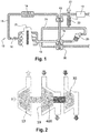
- the architecture represented in figure 1 also called engine system 10, comprises according to one embodiment, an internal combustion engine 17 with compression ignition or controlled, for example diesel or gasoline or other, connected to a circuit 11 for admission of air into the engine , comprising an inlet air filter 12, a compressor 13 for compressing the air for the engine and a cooler 14 downstream of the compressor 13, for cooling the charge air.
- an internal combustion engine 17 with compression ignition or controlled for example diesel or gasoline or other
- a circuit 11 for admission of air into the engine comprising an inlet air filter 12, a compressor 13 for compressing the air for the engine and a cooler 14 downstream of the compressor 13, for cooling the charge air.
- a flow control device 16 such as for example a butterfly valve, makes it possible to control the flow of air admitted into the internal combustion engine 17.
- the latter is connected to a circuit exhaust system 18 which comprises a turbocharger turbine 19, driven by the exhaust gas, coupled to the supercharger compressor 13 to drive it in rotation.
- the exhaust circuit 18 also comprises, downstream of the turbine 19, a device 20 for treating the flue gases.
- EGR exhaust gas recirculation valve or EGR valve exhaust gas recirculation according to the English terminology
- the recirculation circuit 21 is associated with a system 30 of energy recovery coupled to the turbine 19 of the turbocharger.
- this energy recovery system 30 is a turbine 30 for energy recovery, or any other equivalent means.
- This energy recovery turbine 30 is on an energy recovery circuit 24 which is formed downstream of the source of the recirculation circuit 21. exhaust gases.
- the energy recovery circuit 24 also allows the evacuation of the exhaust gases.
- the energy recovery turbine and the energy recovery circuit form the energy recovery system.
- the energy recovery turbine 30 makes it possible to recover the enthalpy normally lost in the recirculation circuit 21 by the pressure drop in the valve CPE.
- the power required to drive the compressor remains virtually unchanged, as well as the flow rate and temperature of the gas passing through the turbine of the turbocharger, the power supply on the turbocharger shaft allows to reduce the expansion ratio at the level of turbocharger turbine, so the exhaust pressure. As a result, the pumped losses are reduced and thus the fuel consumption of the engine.
- the gain provided by the energy recovery system in fuel consumption is illustrated on the figure 3 for a diesel vehicle with a steady speed of 130km / h.
- the coupling between the turbine 19 of the turbocharger and the turbine 30 of energy recovery is achieved by a rigid connection 400 illustrated figure 2 .
- the assembly comprises a system making it possible to decouple the energy recovery turbine 30, for example, during the operating phases requiring a rapid increase in the speed of rotation of the turbocharger, and by example a strong acceleration.
- the decoupling system is a clutch. Specifically, in normal operation with recovery, the clutch is closed, ensuring the connection between the two turbines, so the assistance of the turbocharger. For example, for the revving of the turbocharger, the clutch is open, in order to limit the inertia to accelerate. This solution offers great freedom in terms of system control.
- the decoupling system is a free wheel.
- the recovery turbine In the operating phases where the recovery turbine is of interest, it is driven by the exhaust gas and freewheel is blocked, ensuring the assistance of the turbocharger.
- the assistance is maintained automatically as the power recovered at the additional turbine tends to give it an acceleration greater than that of the turbocharger.
- the freewheel allows the recovery turbine to turn freely, which prevents its inertia from slowing down the speed increase of the turbocharger. This system self-regulates and does not require additional actuator.
- the proposed solution with a decoupling system ensures not only that the response time of the air loop is not greater than the reference case, but can even, in some operating phases, participate in its reduction.
- the recovery turbine contributes to the recovery of the turbocharger.
- the invention applies to a land vehicle, naval or air motor, as well as to generator engines and all other applications using a turbocharged heat engine and low-pressure recirculation of flue gases.
Landscapes
- Engineering & Computer Science (AREA)
- Chemical & Material Sciences (AREA)
- Combustion & Propulsion (AREA)
- Mechanical Engineering (AREA)
- General Engineering & Computer Science (AREA)
- Supercharger (AREA)
- Exhaust-Gas Circulating Devices (AREA)
Abstract
La présente invention concerne un système moteur (10) à circuit (21) de recirculation basse pression des gaz brulés, comportant un moteur thermique équipé d'un circuit (18) d'échappement disposé en sortie du moteur thermique (17), un turbocompresseur comportant une turbine de turbocompresseur (19) disposée sur le circuit d'échappement (18), dans lequel C de récupération d'énergie recevant les gaz d'échappement à basse pression en aval du turbocompresseur, la turbine (30) de récupération d'énergie étant couplée à la turbine (19) du turbocompresseur.The present invention relates to a motor system (10) circuit (21) recirculation low pressure burnt gases, comprising a heat engine equipped with an exhaust circuit (18) disposed at the output of the heat engine (17), a turbocharger having a turbocharger turbine (19) disposed on the exhaust circuit (18), wherein energy recovery C receiving the low pressure exhaust gas downstream of the turbocharger, the recovery turbine (30). energy being coupled to the turbine (19) of the turbocharger.
Description
La présente invention concerne les machines thermiques et plus particulièrement les moteurs à combustion interne à circuit de recirculation des gaz brûlés et turbocompresseur.The present invention relates to thermal machines and more particularly to internal combustion engines with a flue gas recirculation circuit and turbocharger.
De nombreux moteurs à allumage par compression ou commandé équipant les véhicules automobiles sont équipés de turbocompresseurs pour augmenter la pression des gaz admis. Ces turbocompresseurs comportent un compresseur d'air entraîné par une turbine animée par la pression des gaz d'échappement.Many engines with compression ignition or controlled ignition equipping the motor vehicles are equipped with turbochargers to increase the pressure of the admitted gases. These turbochargers comprise an air compressor driven by a turbine driven by the pressure of the exhaust gas.
L'invention s'intéresse plus particulièrement aux systèmes moteurs à recirculation des gaz d'échappement à basse pression, dans lesquels une fraction des gaz d'échappement prélevée en aval de la turbine du turbocompresseur est mélangée aux gaz admis, après traversée d'une vanne de recirculation des gaz d'échappement RGE ou vanne EGR (pour exhaust gaz recirculation selon la terminologie anglaise) EGR créant une chute de pression, les gaz non recirculés étant évacués via une vanne de contre pression à l'échappement ou vanne CPE. Une telle recirculation permet notamment de réduire la teneur en oxydes d'azote (NOx) des gaz d'échappement des moteurs.The invention is more particularly concerned with engine systems with recirculation of low pressure exhaust gases, in which a fraction of the exhaust gases taken downstream of the turbine of the turbocharger is mixed with the admitted gases, after passing through a EGR exhaust gas recirculation valve or EGR valve (for exhaust gas recirculation according to the English terminology) EGR creating a pressure drop, the non-recirculated gases being evacuated via an exhaust pressure valve or CPE valve. Such recirculation notably makes it possible to reduce the nitrogen oxide (NOx) content of the engine exhaust gases.
Un des inconvénients d'une telle architecture provient du fait qu'afin d'assurer un débit de gaz recirculé suffisant, la vanne CPE doit être partiellement fermée, ce qui augmente la pression en amont de cette vanne et donc au niveau du collecteur d'échappement.One of the drawbacks of such an architecture comes from the fact that in order to ensure a sufficient flow of recirculated gas, the valve CPE must be partially closed, which increases the pressure upstream of this valve and therefore at the level of the collector. exhaust.
La présente invention a donc pour objet de pallier un ou plusieurs des inconvénients des dispositifs de l'art antérieur en proposant un ensemble moteur permettant de réduire la pression à l'échappement et ainsi la consommation de carburant.The present invention therefore aims to overcome one or more of the disadvantages of the devices of the prior art by providing an engine assembly to reduce the exhaust pressure and thus the fuel consumption.
Pour cela la présente invention propose un système moteur à circuit de recirculation basse pression des gaz brulés, comportant un moteur thermique équipé d'un circuit d'échappement disposé en sortie du moteur thermique, un turbocompresseur comportant une turbine de turbocompresseur disposée sur le circuit d'échappement, dans lequel le circuit de recirculation est associé à un système de récupération d'énergie recevant les gaz d'échappement à basse pression en aval du turbocompresseur, le système de récupération d'énergie étant couplée à la turbine du turbocompresseur.For this purpose, the present invention proposes a motor system with a low-pressure recirculation circuit for burnt gases, comprising a heat engine equipped with an exhaust circuit disposed at the output of the heat engine, a turbocharger comprising a turbocharger turbine arranged on the fuel circuit. exhaust system, in which the recirculation circuit is associated with a system of energy recovery receiving the low pressure exhaust gas downstream of the turbocharger, the energy recovery system being coupled to the turbine of the turbocharger.
La turbine de récupération d'énergie permet de récupérer l'enthalpie normalement perdue dans le circuit de recirculation.The energy recovery turbine makes it possible to recover the enthalpy normally lost in the recirculation circuit.
Selon un mode de réalisation de l'invention, le système de récupération d'énergie est une turbine.According to one embodiment of the invention, the energy recovery system is a turbine.
Selon un mode de réalisation de l'invention, la turbine du turbocompresseur et le système de récupération d'énergie sont couplés en rotation.According to one embodiment of the invention, the turbocharger turbine and the energy recovery system are coupled in rotation.
Selon un mode de réalisation de l'invention, le couplage entre la turbine du turbocompresseur et le système de récupération d'énergie est réalisé par une liaison rigide.According to one embodiment of the invention, the coupling between the turbocharger turbine and the energy recovery system is achieved by a rigid connection.
Selon un mode de réalisation de l'invention, le système comporte un système de découplage du système de récupération d'énergie.According to one embodiment of the invention, the system comprises a decoupling system of the energy recovery system.
Selon un mode de réalisation de l'invention, le système de découplage est un embrayage.According to one embodiment of the invention, the decoupling system is a clutch.
Selon un mode de réalisation de l'invention, le système de découplage est une roue libre.According to one embodiment of the invention, the decoupling system is a free wheel.
Selon un mode de réalisation de l'invention, le système comportant une vanne en aval de la turbine.According to one embodiment of the invention, the system comprises a valve downstream of the turbine.
Selon un mode de réalisation de l'invention, le moteur thermique étant un moteur à allumage par compression ou commandé.According to one embodiment of the invention, the heat engine is a compression ignition engine or controlled.
L'invention concerne également, un véhicule, notamment automobile, équipé d'un système moteur tel que défini selon l'invention.The invention also relates to a vehicle, in particular an automobile, equipped with a motor system as defined according to the invention.
D'autres buts, caractéristiques et avantages de l'invention seront mieux compris et apparaîtront plus clairement à la lecture de la description faite, ci-après, en se référant aux figures annexées, données à titre d'exemple et dans lesquelles:
- la
figure 1 représente une architecture moteur avec un système de récupération d'énergie selon un premier mode de réalisation de l'invention, - la
figure 2 est une représentation schématique du système de récupération d'énergie de l'invention, - la
figure 3 illustre le gain potentiel en consommation avec le système selon l'invention.
- the
figure 1 represents an engine architecture with an energy recovery system according to a first embodiment of the invention, - the
figure 2 is a schematic representation of the energy recovery system of the invention, - the
figure 3 illustrates the potential gain in consumption with the system according to the invention.
L'architecture représentée à la
Selon un mode de réalisation de l'invention, un dispositif de réglage de débit 16, tel que par exemple une vanne papillon, permet de contrôler le débit d'air admis dans le moteur à combustion interne 17. Ce dernier est relié à un circuit d'échappement 18 qui comporte une turbine 19 de turbocompresseur, entraînée par les gaz d'échappement, accouplée au compresseur 13 de suralimentation pour l'entraîner en rotation.According to one embodiment of the invention, a
Le circuit d'échappement 18 comporte également, en aval de la turbine 19, un dispositif 20 de traitement des gaz brûlés.The
Un circuit 21 de recirculation des gaz brulés basse pression prenant sa source en aval de la turbine 19 et muni par exemple d'un refroidisseur 22 capte une partie des gaz brûlés pour les réinjecter avec un débit contrôlé dans le moteur 17, par l'intermédiaire d'une vanne 23 dite vanne de recirculation des gaz d'échappement RGE ou vanne EGR (pour exhaust gas recirculation selon la terminologie anglaise), disposée en amont du turbocompresseur, qui crée une perte de charge suffisante.A low-pressure burnt
Dans le cadre de l'invention, le circuit 21 de recirculation est associé à un système 30 de récupération d'énergie couplé à la turbine 19 du turbocompresseur.In the context of the invention, the
Selon un mode de réalisation de l'invention, ce système 30 de récupération d'énergie est une turbine 30 de récupération d'énergie, ou tout autre moyen équivalent.According to one embodiment of the invention, this
Cette turbine 30 de récupération d'énergie est sur un circuit 24 de récupération d'énergie qui est formé en aval de la source du circuit 21 de recirculation des gaz de d'échappement. Le circuit 24 de récupération d'énergie permet aussi l'évacuation des gaz d'échappement.This
Selon un autre mode de réalisation de l'invention, la turbine de récupération d'énergie et le circuit de récupération d'énergie forment le système de récupération d'énergie.According to another embodiment of the invention, the energy recovery turbine and the energy recovery circuit form the energy recovery system.
La turbine 30 de récupération d'énergie permet de récupérer l'enthalpie normalement perdue dans le circuit 21 de recirculation par la perte de charge dans la vanne CPE.The
La puissance nécessaire à l'entraînement du compresseur restant pratiquement inchangée, de même que le débit et la température des gaz traversant la turbine du turbocompresseur, l'apport de puissance sur l'arbre du turbocompresseur permet de diminuer le rapport de détente au niveau de la turbine du turbocompresseur, donc la pression à l'échappement. Par conséquent, les pertes par pompage sont réduites et donc la consommation de carburant du moteur. Le gain apporté par le système de récupération d'énergie en consommation de carburant est illustré sur la
Le couplage entre la turbine 19 du turbocompresseur et la turbine 30 de récupération d'énergie est réalisé par une liaison rigide 400 illustrée
Selon un mode de réalisation de l'invention, l'ensemble comporte un système permettant de découpler la turbine 30 de récupération d'énergie, par exemple, lors des phases de fonctionnement nécessitant un accroissement rapide de la vitesse de rotation du turbocompresseur, et par exemple une forte accélération.According to one embodiment of the invention, the assembly comprises a system making it possible to decouple the
Selon un mode de réalisation de l'invention, le système de découplage est un embrayage. Plus précisément, en fonctionnement normal avec récupération, l'embrayage est fermé, assurant la liaison entre les deux turbines, donc l'assistance du turbocompresseur. Par exemple, pour la montée en régime du turbocompresseur, l'embrayage est ouvert, afin de limiter l'inertie à accélérer. Cette solution offre une grande liberté en terme de pilotage du système.According to one embodiment of the invention, the decoupling system is a clutch. Specifically, in normal operation with recovery, the clutch is closed, ensuring the connection between the two turbines, so the assistance of the turbocharger. For example, for the revving of the turbocharger, the clutch is open, in order to limit the inertia to accelerate. This solution offers great freedom in terms of system control.
Selon un autre mode de réalisation de l'invention, le système de découplage est une roue libre. Dans les phases de fonctionnement où la turbine de récupération présente un intérêt, celle-ci est entraînée par les gaz d'échappement et la roue libre se bloque, assurant l'assistance du turbocompresseur. Lors des phases de montée en vitesse du turbocompresseur, l'assistance se maintient automatiquement tant que la puissance récupérée au niveau de la turbine additionnelle tend à lui conférer une accélération supérieure à celle du turbocompresseur. Dans le cas contraire, la roue libre laisse la turbine de récupération tourner librement, ce qui évite que son inertie ne freine la montée en vitesse du turbocompresseur. Ce système s'autorégule et ne nécessite pas d'actionneur additionnel.According to another embodiment of the invention, the decoupling system is a free wheel. In the operating phases where the recovery turbine is of interest, it is driven by the exhaust gas and freewheel is blocked, ensuring the assistance of the turbocharger. During the turbocharger's speed up phases, the assistance is maintained automatically as the power recovered at the additional turbine tends to give it an acceleration greater than that of the turbocharger. In the opposite case, the freewheel allows the recovery turbine to turn freely, which prevents its inertia from slowing down the speed increase of the turbocharger. This system self-regulates and does not require additional actuator.
Ainsi, la solution proposée avec un système de découplage, assure non seulement que le temps de réponse de la boucle d'air n'est pas supérieur au cas de référence, mais peut même, dans certaines phases de fonctionnement, participer à sa réduction.Thus, the proposed solution with a decoupling system, ensures not only that the response time of the air loop is not greater than the reference case, but can even, in some operating phases, participate in its reduction.
Le potentiel de récupération d'énergie d'un tel système selon l'invention peut s'écrire de la façon suivante : 
La dynamique de montée en vitesse du turbocompresseur d'un tel système selon l'invention peut s'écrire de la façon suivante :
- Dans le cas de l'architecture de référence, la dynamique de vitesse du turbocompresseur :

- In the case of the reference architecture, the speed dynamics of the turbocharger:
Avec le système de récupération, dans le cas d'une liaison rigide entre les deux turbines : 
Si ![]()
![]()
Dans le cas d'un couplage par embrayage ou par roue libre :
- Si la condition (3) se trouve vérifiée les deux turbines sont désaccouplées et l'on retrouve la dynamique de référence donnée par l'équation (1).
- If condition (3) is satisfied both turbines are uncoupled and we find the reference dynamic given by equation (1).
Dans le cas contraire, les turbines sont accouplées. La turbine de récupération contribue à la relance du turbocompresseur.Otherwise, the turbines are coupled. The recovery turbine contributes to the recovery of the turbocharger.
Comme ![]()
![]()
Avec
- cp :
- capacité calorifique des gaz à pression constante
- J :
- inertie
- Q :
- débit massique
- Pu :
- pression en amont de l'élément considéré
- Pd :
- pression en aval de l'élément considéré
- Wc :
- puissance mécanique du compresseur du turbocompresseur
- Wt :
- puissance mécanique de la turbine du turbocompresseur
- Wr :
- puissance mécanique de la turbine de la turbine de récupération
- η :
- rendement isentropique
- ω :
- vitesse de rotation
- Xt :
- turbine du turbocompresseur
- Xr :
- turbine de récupération
- X 0:
- configuration de référence
- t :
- temps,
- Xegr :
- circuit de recirculation
- γ :
- indice adiabatique du gaz considéré
- cp :
- heat capacity of gases at constant pressure
- J :
- inertia
- Q :
- mass flow
- P u :
- pressure upstream of the considered element
- P d :
- downstream pressure of the considered element
- W c :
- mechanical power of the turbocharger compressor
- W t :
- mechanical power of turbocharger turbine
- W r :
- mechanical power of the turbine of the recovery turbine
- η :
- isentropic efficiency
- ω :
- rotation speed
- X t :
- turbocharger turbine
- X r :
- recovery turbine
- X 0 :
- reference configuration
- t :
- time,
- Xegr:
- recirculation circuit
- γ :
- adiabatic index of the gas considered
L'invention s'applique à un moteur de véhicule terrestre, naval ou aérien, ainsi qu'aux moteurs de groupes électrogènes et à toutes autres applications utilisant un moteur thermique à turbocompresseur et recirculation basse pression des gaz brûlés.The invention applies to a land vehicle, naval or air motor, as well as to generator engines and all other applications using a turbocharged heat engine and low-pressure recirculation of flue gases.
La portée de la présente invention ne se limite pas aux détails donnés ci-dessus et permet des modes de réalisation sous de nombreuses autres formes spécifiques sans s'éloigner du domaine d'application de l'invention. Par conséquent, les présents modes de réalisation doivent être considérés à titre d'illustration, et peuvent être modifiés sans toutefois sortir de la portée définie par les revendications.The scope of the present invention is not limited to the details given above and allows embodiments in many other specific forms without departing from the scope of the invention. Therefore, the present embodiments should be considered by way of illustration, and may be modified without departing from the scope defined by the claims.
Claims (10)
Applications Claiming Priority (1)
| Application Number | Priority Date | Filing Date | Title |
|---|---|---|---|
| FR1561541A FR3044363B1 (en) | 2015-11-30 | 2015-11-30 | ENGINE SYSTEM WITH BURN GAS RECIRCULATION CIRCUIT |
Publications (1)
| Publication Number | Publication Date |
|---|---|
| EP3173598A1 true EP3173598A1 (en) | 2017-05-31 |
Family
ID=57286534
Family Applications (1)
| Application Number | Title | Priority Date | Filing Date |
|---|---|---|---|
| EP16201414.6A Withdrawn EP3173598A1 (en) | 2015-11-30 | 2016-11-30 | Motor system with circuit for recirculating exhaust gases |
Country Status (2)
| Country | Link |
|---|---|
| EP (1) | EP3173598A1 (en) |
| FR (1) | FR3044363B1 (en) |
Citations (8)
| Publication number | Priority date | Publication date | Assignee | Title |
|---|---|---|---|---|
| JP2005069092A (en) * | 2003-08-25 | 2005-03-17 | Nissan Diesel Motor Co Ltd | Exhaust gas recirculation device of turbo compound engine |
| EP1903197A2 (en) * | 2006-07-27 | 2008-03-26 | Iveco S.p.A. | Engine with energy recovery and catalytic exhaust gas treatment process |
| US20090205326A1 (en) * | 2008-02-14 | 2009-08-20 | Dresser, Inc. | Recirculation of Exhaust Gas Condensate |
| DE102011108204A1 (en) * | 2011-07-20 | 2013-01-24 | Daimler Ag | Internal combustion engine for motor vehicle, has actuating device comprising control element by which pressure in the exhaust gas duct is adjustable at branching point |
| FR3005996A1 (en) * | 2013-05-21 | 2014-11-28 | Peugeot Citroen Automobiles Sa | DEVICE FOR HOMOGENEOUS RECIRCULATION OF EXHAUST GAS |
| WO2015086935A1 (en) * | 2013-12-13 | 2015-06-18 | Renault S.A.S. | Exhaust line for an internal combustion engine and internal combustion engine comprising such an exhaust line |
| WO2015197994A1 (en) * | 2014-06-26 | 2015-12-30 | Valeo Systemes De Controle Moteur | Engine system comprising a circuit for the low-pressure recirculation of burnt gases |
| WO2015197993A1 (en) * | 2014-06-26 | 2015-12-30 | Valeo Systemes De Controle Moteur | Engine system comprising a burnt gas recirculation circuit |
-
2015
- 2015-11-30 FR FR1561541A patent/FR3044363B1/en active Active
-
2016
- 2016-11-30 EP EP16201414.6A patent/EP3173598A1/en not_active Withdrawn
Patent Citations (8)
| Publication number | Priority date | Publication date | Assignee | Title |
|---|---|---|---|---|
| JP2005069092A (en) * | 2003-08-25 | 2005-03-17 | Nissan Diesel Motor Co Ltd | Exhaust gas recirculation device of turbo compound engine |
| EP1903197A2 (en) * | 2006-07-27 | 2008-03-26 | Iveco S.p.A. | Engine with energy recovery and catalytic exhaust gas treatment process |
| US20090205326A1 (en) * | 2008-02-14 | 2009-08-20 | Dresser, Inc. | Recirculation of Exhaust Gas Condensate |
| DE102011108204A1 (en) * | 2011-07-20 | 2013-01-24 | Daimler Ag | Internal combustion engine for motor vehicle, has actuating device comprising control element by which pressure in the exhaust gas duct is adjustable at branching point |
| FR3005996A1 (en) * | 2013-05-21 | 2014-11-28 | Peugeot Citroen Automobiles Sa | DEVICE FOR HOMOGENEOUS RECIRCULATION OF EXHAUST GAS |
| WO2015086935A1 (en) * | 2013-12-13 | 2015-06-18 | Renault S.A.S. | Exhaust line for an internal combustion engine and internal combustion engine comprising such an exhaust line |
| WO2015197994A1 (en) * | 2014-06-26 | 2015-12-30 | Valeo Systemes De Controle Moteur | Engine system comprising a circuit for the low-pressure recirculation of burnt gases |
| WO2015197993A1 (en) * | 2014-06-26 | 2015-12-30 | Valeo Systemes De Controle Moteur | Engine system comprising a burnt gas recirculation circuit |
Also Published As
| Publication number | Publication date |
|---|---|
| FR3044363B1 (en) | 2019-08-30 |
| FR3044363A1 (en) | 2017-06-02 |
Similar Documents
| Publication | Publication Date | Title |
|---|---|---|
| EP3161289B1 (en) | Engine system with exhaust gas recirculation circuit | |
| EP1771649B1 (en) | Device and method for boosting an intake tube of a turbocharged engine with compressed air | |
| EP3092382B1 (en) | Exhaust gas line of an internal combustion engine and internal combustion engine with such an exhaust gas line | |
| FR3046434A1 (en) | A DOUBLE DUCT DRAIN POWER TURBINE SYSTEM AND METHOD FOR CONTROLLING THE SAME | |
| WO2018083400A1 (en) | System for injecting air into a gas exhaust circuit of a supercharged heat engine | |
| EP3173597B1 (en) | Motor system with circuit for recirculating exhaust gases | |
| EP3161290B1 (en) | Engine system with low pressure exhaust gas recirculation | |
| FR3044363B1 (en) | ENGINE SYSTEM WITH BURN GAS RECIRCULATION CIRCUIT | |
| EP3084164A1 (en) | Assembly comprising a heat engine and an electrical compressor | |
| EP3179070B1 (en) | Motor system with energy recovery system | |
| EP3084167A1 (en) | Assembly including a heat engine and an electrical compressor configured such as to scavenge residual burnt gases | |
| CN107725176B (en) | Turbocharger with dual wastegate valve | |
| WO2017093661A1 (en) | Engine system comprising energy recovery system and low-pressure circuit for recirculating burned gases | |
| WO2016151270A1 (en) | Engine system with energy recovery system | |
| FR2927364A1 (en) | Supercharged internal combustion engine i.e. supercharged oil engine, for terrestrial vehicle, has connection device placed in such manner that air and gas circulating are introduced in intake circuit while creating swirling movement | |
| FR2803628A1 (en) | METHOD AND DEVICE FOR DECREASING THE RESPONSE TIME TO ACCELERATION OF SUPERCHARGED THERMAL ENGINES | |
| WO2018002561A1 (en) | Engine system comprising a burnt gas recirculation circuit | |
| FR2904051A1 (en) | Particle filter regenerating method for internal combustion engine i.e. oil engine, of motor vehicle, involves injecting fuel in combustion chamber during gas injection and compression, and opening exhaust valve during gas compression | |
| EP4276297A1 (en) | Method for adjusting the partial recirculation of exhaust gases to the intake of a diesel engine | |
| FR3133403A1 (en) | TURBOMACHINE DEVICE WITH COMBUSTION CHAMBERS OF DIFFERENT CONFIGURATIONS AND VEHICLE COMPRISING SUCH A DEVICE | |
| FR2933740A1 (en) | Internal combustion engine e.g. diesel engine, controlling method for motor vehicle, involves circulating gas flow such that volume ratio of gas to other gases is in specific percentage range, when engine operates at low speed and full load | |
| FR3060054A1 (en) | PROCESS FOR RECIRCULATING GASES BURNED WITH AN ELECTRICAL COMPRESSOR | |
| FR3058465A1 (en) | ARRANGEMENT OF SHUTTER AGAINST FLOW | |
| FR2889560A1 (en) | Air admission loop function control system for motor vehicle diesel engine, has control unit regulating functioning of valve to regulate intake pressure of gas in engine inlet when turbine of turbocharger is in full open position |
Legal Events
| Date | Code | Title | Description |
|---|---|---|---|
| PUAI | Public reference made under article 153(3) epc to a published international application that has entered the european phase |
Free format text: ORIGINAL CODE: 0009012 |
|
| 17P | Request for examination filed |
Effective date: 20161130 |
|
| AK | Designated contracting states |
Kind code of ref document: A1 Designated state(s): AL AT BE BG CH CY CZ DE DK EE ES FI FR GB GR HR HU IE IS IT LI LT LU LV MC MK MT NL NO PL PT RO RS SE SI SK SM TR |
|
| AX | Request for extension of the european patent |
Extension state: BA ME |
|
| 17Q | First examination report despatched |
Effective date: 20170511 |
|
| GRAP | Despatch of communication of intention to grant a patent |
Free format text: ORIGINAL CODE: EPIDOSNIGR1 |
|
| INTG | Intention to grant announced |
Effective date: 20181017 |
|
| STAA | Information on the status of an ep patent application or granted ep patent |
Free format text: STATUS: THE APPLICATION IS DEEMED TO BE WITHDRAWN |
|
| 18D | Application deemed to be withdrawn |
Effective date: 20190228 |