EP3173392A1 - Verfahren und vorrichtung zur herstellung von keramikteilen - Google Patents
Verfahren und vorrichtung zur herstellung von keramikteilen Download PDFInfo
- Publication number
- EP3173392A1 EP3173392A1 EP16200487.3A EP16200487A EP3173392A1 EP 3173392 A1 EP3173392 A1 EP 3173392A1 EP 16200487 A EP16200487 A EP 16200487A EP 3173392 A1 EP3173392 A1 EP 3173392A1
- Authority
- EP
- European Patent Office
- Prior art keywords
- ceramic
- additive
- ceramic part
- sintering
- sintered
- Prior art date
- Legal status (The legal status is an assumption and is not a legal conclusion. Google has not performed a legal analysis and makes no representation as to the accuracy of the status listed.)
- Granted
Links
Images

Classifications
-
- C—CHEMISTRY; METALLURGY
- C04—CEMENTS; CONCRETE; ARTIFICIAL STONE; CERAMICS; REFRACTORIES
- C04B—LIME, MAGNESIA; SLAG; CEMENTS; COMPOSITIONS THEREOF, e.g. MORTARS, CONCRETE OR LIKE BUILDING MATERIALS; ARTIFICIAL STONE; CERAMICS; REFRACTORIES; TREATMENT OF NATURAL STONE
- C04B35/00—Shaped ceramic products characterised by their composition; Ceramics compositions; Processing powders of inorganic compounds preparatory to the manufacturing of ceramic products
- C04B35/01—Shaped ceramic products characterised by their composition; Ceramics compositions; Processing powders of inorganic compounds preparatory to the manufacturing of ceramic products based on oxide ceramics
- C04B35/48—Shaped ceramic products characterised by their composition; Ceramics compositions; Processing powders of inorganic compounds preparatory to the manufacturing of ceramic products based on oxide ceramics based on zirconium or hafnium oxides, zirconates, zircon or hafnates
- C04B35/486—Fine ceramics
-
- C—CHEMISTRY; METALLURGY
- C04—CEMENTS; CONCRETE; ARTIFICIAL STONE; CERAMICS; REFRACTORIES
- C04B—LIME, MAGNESIA; SLAG; CEMENTS; COMPOSITIONS THEREOF, e.g. MORTARS, CONCRETE OR LIKE BUILDING MATERIALS; ARTIFICIAL STONE; CERAMICS; REFRACTORIES; TREATMENT OF NATURAL STONE
- C04B35/00—Shaped ceramic products characterised by their composition; Ceramics compositions; Processing powders of inorganic compounds preparatory to the manufacturing of ceramic products
- C04B35/622—Forming processes; Processing powders of inorganic compounds preparatory to the manufacturing of ceramic products
- C04B35/626—Preparing or treating the powders individually or as batches ; preparing or treating macroscopic reinforcing agents for ceramic products, e.g. fibres; mechanical aspects section B
- C04B35/63—Preparing or treating the powders individually or as batches ; preparing or treating macroscopic reinforcing agents for ceramic products, e.g. fibres; mechanical aspects section B using additives specially adapted for forming the products, e.g.. binder binders
- C04B35/638—Removal thereof
-
- C—CHEMISTRY; METALLURGY
- C04—CEMENTS; CONCRETE; ARTIFICIAL STONE; CERAMICS; REFRACTORIES
- C04B—LIME, MAGNESIA; SLAG; CEMENTS; COMPOSITIONS THEREOF, e.g. MORTARS, CONCRETE OR LIKE BUILDING MATERIALS; ARTIFICIAL STONE; CERAMICS; REFRACTORIES; TREATMENT OF NATURAL STONE
- C04B35/00—Shaped ceramic products characterised by their composition; Ceramics compositions; Processing powders of inorganic compounds preparatory to the manufacturing of ceramic products
- C04B35/622—Forming processes; Processing powders of inorganic compounds preparatory to the manufacturing of ceramic products
- C04B35/64—Burning or sintering processes
- C04B35/645—Pressure sintering
- C04B35/6455—Hot isostatic pressing
-
- A—HUMAN NECESSITIES
- A61—MEDICAL OR VETERINARY SCIENCE; HYGIENE
- A61C—DENTISTRY; APPARATUS OR METHODS FOR ORAL OR DENTAL HYGIENE
- A61C13/00—Dental prostheses; Making same
- A61C13/0003—Making bridge-work, inlays, implants or the like
- A61C13/0006—Production methods
- A61C13/0013—Production methods using stereolithographic techniques
-
- A—HUMAN NECESSITIES
- A61—MEDICAL OR VETERINARY SCIENCE; HYGIENE
- A61C—DENTISTRY; APPARATUS OR METHODS FOR ORAL OR DENTAL HYGIENE
- A61C13/00—Dental prostheses; Making same
- A61C13/0003—Making bridge-work, inlays, implants or the like
- A61C13/0022—Blanks or green, unfinished dental restoration parts
-
- A—HUMAN NECESSITIES
- A61—MEDICAL OR VETERINARY SCIENCE; HYGIENE
- A61C—DENTISTRY; APPARATUS OR METHODS FOR ORAL OR DENTAL HYGIENE
- A61C8/00—Means to be fixed to the jaw-bone for consolidating natural teeth or for fixing dental prostheses thereon; Dental implants; Implanting tools
- A61C8/0012—Means to be fixed to the jaw-bone for consolidating natural teeth or for fixing dental prostheses thereon; Dental implants; Implanting tools characterised by the material or composition, e.g. ceramics, surface layer, metal alloy
-
- C—CHEMISTRY; METALLURGY
- C04—CEMENTS; CONCRETE; ARTIFICIAL STONE; CERAMICS; REFRACTORIES
- C04B—LIME, MAGNESIA; SLAG; CEMENTS; COMPOSITIONS THEREOF, e.g. MORTARS, CONCRETE OR LIKE BUILDING MATERIALS; ARTIFICIAL STONE; CERAMICS; REFRACTORIES; TREATMENT OF NATURAL STONE
- C04B2235/00—Aspects relating to ceramic starting mixtures or sintered ceramic products
- C04B2235/02—Composition of constituents of the starting material or of secondary phases of the final product
- C04B2235/30—Constituents and secondary phases not being of a fibrous nature
- C04B2235/32—Metal oxides, mixed metal oxides, or oxide-forming salts thereof, e.g. carbonates, nitrates, (oxy)hydroxides, chlorides
- C04B2235/3231—Refractory metal oxides, their mixed metal oxides, or oxide-forming salts thereof
- C04B2235/3244—Zirconium oxides, zirconates, hafnium oxides, hafnates, or oxide-forming salts thereof
- C04B2235/3246—Stabilised zirconias, e.g. YSZ or cerium stabilised zirconia
-
- C—CHEMISTRY; METALLURGY
- C04—CEMENTS; CONCRETE; ARTIFICIAL STONE; CERAMICS; REFRACTORIES
- C04B—LIME, MAGNESIA; SLAG; CEMENTS; COMPOSITIONS THEREOF, e.g. MORTARS, CONCRETE OR LIKE BUILDING MATERIALS; ARTIFICIAL STONE; CERAMICS; REFRACTORIES; TREATMENT OF NATURAL STONE
- C04B2235/00—Aspects relating to ceramic starting mixtures or sintered ceramic products
- C04B2235/02—Composition of constituents of the starting material or of secondary phases of the final product
- C04B2235/30—Constituents and secondary phases not being of a fibrous nature
- C04B2235/34—Non-metal oxides, non-metal mixed oxides, or salts thereof that form the non-metal oxides upon heating, e.g. carbonates, nitrates, (oxy)hydroxides, chlorides
- C04B2235/3418—Silicon oxide, silicic acids or oxide forming salts thereof, e.g. silica sol, fused silica, silica fume, cristobalite, quartz or flint
-
- C—CHEMISTRY; METALLURGY
- C04—CEMENTS; CONCRETE; ARTIFICIAL STONE; CERAMICS; REFRACTORIES
- C04B—LIME, MAGNESIA; SLAG; CEMENTS; COMPOSITIONS THEREOF, e.g. MORTARS, CONCRETE OR LIKE BUILDING MATERIALS; ARTIFICIAL STONE; CERAMICS; REFRACTORIES; TREATMENT OF NATURAL STONE
- C04B2235/00—Aspects relating to ceramic starting mixtures or sintered ceramic products
- C04B2235/02—Composition of constituents of the starting material or of secondary phases of the final product
- C04B2235/30—Constituents and secondary phases not being of a fibrous nature
- C04B2235/42—Non metallic elements added as constituents or additives, e.g. sulfur, phosphor, selenium or tellurium
- C04B2235/422—Carbon
-
- C—CHEMISTRY; METALLURGY
- C04—CEMENTS; CONCRETE; ARTIFICIAL STONE; CERAMICS; REFRACTORIES
- C04B—LIME, MAGNESIA; SLAG; CEMENTS; COMPOSITIONS THEREOF, e.g. MORTARS, CONCRETE OR LIKE BUILDING MATERIALS; ARTIFICIAL STONE; CERAMICS; REFRACTORIES; TREATMENT OF NATURAL STONE
- C04B2235/00—Aspects relating to ceramic starting mixtures or sintered ceramic products
- C04B2235/02—Composition of constituents of the starting material or of secondary phases of the final product
- C04B2235/30—Constituents and secondary phases not being of a fibrous nature
- C04B2235/42—Non metallic elements added as constituents or additives, e.g. sulfur, phosphor, selenium or tellurium
- C04B2235/428—Silicon
-
- C—CHEMISTRY; METALLURGY
- C04—CEMENTS; CONCRETE; ARTIFICIAL STONE; CERAMICS; REFRACTORIES
- C04B—LIME, MAGNESIA; SLAG; CEMENTS; COMPOSITIONS THEREOF, e.g. MORTARS, CONCRETE OR LIKE BUILDING MATERIALS; ARTIFICIAL STONE; CERAMICS; REFRACTORIES; TREATMENT OF NATURAL STONE
- C04B2235/00—Aspects relating to ceramic starting mixtures or sintered ceramic products
- C04B2235/02—Composition of constituents of the starting material or of secondary phases of the final product
- C04B2235/30—Constituents and secondary phases not being of a fibrous nature
- C04B2235/44—Metal salt constituents or additives chosen for the nature of the anions, e.g. hydrides or acetylacetonate
- C04B2235/444—Halide containing anions, e.g. bromide, iodate, chlorite
-
- C—CHEMISTRY; METALLURGY
- C04—CEMENTS; CONCRETE; ARTIFICIAL STONE; CERAMICS; REFRACTORIES
- C04B—LIME, MAGNESIA; SLAG; CEMENTS; COMPOSITIONS THEREOF, e.g. MORTARS, CONCRETE OR LIKE BUILDING MATERIALS; ARTIFICIAL STONE; CERAMICS; REFRACTORIES; TREATMENT OF NATURAL STONE
- C04B2235/00—Aspects relating to ceramic starting mixtures or sintered ceramic products
- C04B2235/02—Composition of constituents of the starting material or of secondary phases of the final product
- C04B2235/30—Constituents and secondary phases not being of a fibrous nature
- C04B2235/44—Metal salt constituents or additives chosen for the nature of the anions, e.g. hydrides or acetylacetonate
- C04B2235/448—Sulphates or sulphites
-
- C—CHEMISTRY; METALLURGY
- C04—CEMENTS; CONCRETE; ARTIFICIAL STONE; CERAMICS; REFRACTORIES
- C04B—LIME, MAGNESIA; SLAG; CEMENTS; COMPOSITIONS THEREOF, e.g. MORTARS, CONCRETE OR LIKE BUILDING MATERIALS; ARTIFICIAL STONE; CERAMICS; REFRACTORIES; TREATMENT OF NATURAL STONE
- C04B2235/00—Aspects relating to ceramic starting mixtures or sintered ceramic products
- C04B2235/02—Composition of constituents of the starting material or of secondary phases of the final product
- C04B2235/30—Constituents and secondary phases not being of a fibrous nature
- C04B2235/44—Metal salt constituents or additives chosen for the nature of the anions, e.g. hydrides or acetylacetonate
- C04B2235/449—Organic acids, e.g. EDTA, citrate, acetate, oxalate
-
- C—CHEMISTRY; METALLURGY
- C04—CEMENTS; CONCRETE; ARTIFICIAL STONE; CERAMICS; REFRACTORIES
- C04B—LIME, MAGNESIA; SLAG; CEMENTS; COMPOSITIONS THEREOF, e.g. MORTARS, CONCRETE OR LIKE BUILDING MATERIALS; ARTIFICIAL STONE; CERAMICS; REFRACTORIES; TREATMENT OF NATURAL STONE
- C04B2235/00—Aspects relating to ceramic starting mixtures or sintered ceramic products
- C04B2235/02—Composition of constituents of the starting material or of secondary phases of the final product
- C04B2235/50—Constituents or additives of the starting mixture chosen for their shape or used because of their shape or their physical appearance
- C04B2235/54—Particle size related information
- C04B2235/5418—Particle size related information expressed by the size of the particles or aggregates thereof
- C04B2235/5445—Particle size related information expressed by the size of the particles or aggregates thereof submicron sized, i.e. from 0,1 to 1 micron
-
- C—CHEMISTRY; METALLURGY
- C04—CEMENTS; CONCRETE; ARTIFICIAL STONE; CERAMICS; REFRACTORIES
- C04B—LIME, MAGNESIA; SLAG; CEMENTS; COMPOSITIONS THEREOF, e.g. MORTARS, CONCRETE OR LIKE BUILDING MATERIALS; ARTIFICIAL STONE; CERAMICS; REFRACTORIES; TREATMENT OF NATURAL STONE
- C04B2235/00—Aspects relating to ceramic starting mixtures or sintered ceramic products
- C04B2235/60—Aspects relating to the preparation, properties or mechanical treatment of green bodies or pre-forms
- C04B2235/602—Making the green bodies or pre-forms by moulding
- C04B2235/6021—Extrusion moulding
-
- C—CHEMISTRY; METALLURGY
- C04—CEMENTS; CONCRETE; ARTIFICIAL STONE; CERAMICS; REFRACTORIES
- C04B—LIME, MAGNESIA; SLAG; CEMENTS; COMPOSITIONS THEREOF, e.g. MORTARS, CONCRETE OR LIKE BUILDING MATERIALS; ARTIFICIAL STONE; CERAMICS; REFRACTORIES; TREATMENT OF NATURAL STONE
- C04B2235/00—Aspects relating to ceramic starting mixtures or sintered ceramic products
- C04B2235/60—Aspects relating to the preparation, properties or mechanical treatment of green bodies or pre-forms
- C04B2235/602—Making the green bodies or pre-forms by moulding
- C04B2235/6022—Injection moulding
-
- C—CHEMISTRY; METALLURGY
- C04—CEMENTS; CONCRETE; ARTIFICIAL STONE; CERAMICS; REFRACTORIES
- C04B—LIME, MAGNESIA; SLAG; CEMENTS; COMPOSITIONS THEREOF, e.g. MORTARS, CONCRETE OR LIKE BUILDING MATERIALS; ARTIFICIAL STONE; CERAMICS; REFRACTORIES; TREATMENT OF NATURAL STONE
- C04B2235/00—Aspects relating to ceramic starting mixtures or sintered ceramic products
- C04B2235/60—Aspects relating to the preparation, properties or mechanical treatment of green bodies or pre-forms
- C04B2235/602—Making the green bodies or pre-forms by moulding
- C04B2235/6026—Computer aided shaping, e.g. rapid prototyping
-
- C—CHEMISTRY; METALLURGY
- C04—CEMENTS; CONCRETE; ARTIFICIAL STONE; CERAMICS; REFRACTORIES
- C04B—LIME, MAGNESIA; SLAG; CEMENTS; COMPOSITIONS THEREOF, e.g. MORTARS, CONCRETE OR LIKE BUILDING MATERIALS; ARTIFICIAL STONE; CERAMICS; REFRACTORIES; TREATMENT OF NATURAL STONE
- C04B2235/00—Aspects relating to ceramic starting mixtures or sintered ceramic products
- C04B2235/60—Aspects relating to the preparation, properties or mechanical treatment of green bodies or pre-forms
- C04B2235/612—Machining
-
- C—CHEMISTRY; METALLURGY
- C04—CEMENTS; CONCRETE; ARTIFICIAL STONE; CERAMICS; REFRACTORIES
- C04B—LIME, MAGNESIA; SLAG; CEMENTS; COMPOSITIONS THEREOF, e.g. MORTARS, CONCRETE OR LIKE BUILDING MATERIALS; ARTIFICIAL STONE; CERAMICS; REFRACTORIES; TREATMENT OF NATURAL STONE
- C04B2235/00—Aspects relating to ceramic starting mixtures or sintered ceramic products
- C04B2235/60—Aspects relating to the preparation, properties or mechanical treatment of green bodies or pre-forms
- C04B2235/616—Liquid infiltration of green bodies or pre-forms
-
- C—CHEMISTRY; METALLURGY
- C04—CEMENTS; CONCRETE; ARTIFICIAL STONE; CERAMICS; REFRACTORIES
- C04B—LIME, MAGNESIA; SLAG; CEMENTS; COMPOSITIONS THEREOF, e.g. MORTARS, CONCRETE OR LIKE BUILDING MATERIALS; ARTIFICIAL STONE; CERAMICS; REFRACTORIES; TREATMENT OF NATURAL STONE
- C04B2235/00—Aspects relating to ceramic starting mixtures or sintered ceramic products
- C04B2235/70—Aspects relating to sintered or melt-casted ceramic products
- C04B2235/74—Physical characteristics
- C04B2235/77—Density
-
- C—CHEMISTRY; METALLURGY
- C04—CEMENTS; CONCRETE; ARTIFICIAL STONE; CERAMICS; REFRACTORIES
- C04B—LIME, MAGNESIA; SLAG; CEMENTS; COMPOSITIONS THEREOF, e.g. MORTARS, CONCRETE OR LIKE BUILDING MATERIALS; ARTIFICIAL STONE; CERAMICS; REFRACTORIES; TREATMENT OF NATURAL STONE
- C04B2235/00—Aspects relating to ceramic starting mixtures or sintered ceramic products
- C04B2235/70—Aspects relating to sintered or melt-casted ceramic products
- C04B2235/80—Phases present in the sintered or melt-cast ceramic products other than the main phase
-
- C—CHEMISTRY; METALLURGY
- C04—CEMENTS; CONCRETE; ARTIFICIAL STONE; CERAMICS; REFRACTORIES
- C04B—LIME, MAGNESIA; SLAG; CEMENTS; COMPOSITIONS THEREOF, e.g. MORTARS, CONCRETE OR LIKE BUILDING MATERIALS; ARTIFICIAL STONE; CERAMICS; REFRACTORIES; TREATMENT OF NATURAL STONE
- C04B2235/00—Aspects relating to ceramic starting mixtures or sintered ceramic products
- C04B2235/70—Aspects relating to sintered or melt-casted ceramic products
- C04B2235/96—Properties of ceramic products, e.g. mechanical properties such as strength, toughness, wear resistance
- C04B2235/9607—Thermal properties, e.g. thermal expansion coefficient
- C04B2235/9615—Linear firing shrinkage
Definitions
- the invention relates to a method for producing ceramic parts according to independent claim 1 and to a device according to claim 15.
- Ceramics have established themselves for many applications because of their advantageous material properties. Depending on the ceramic material used, properties can be obtained which would not be possible with other materials such as metals and polymers in this way and combination.
- Advantageous properties of various ceramic materials include high mechanical strength and rigidity, high hardness and abrasion resistance, heat resistance, high dielectric constants and good biocompatibility.
- US2001053937A a method for the production of bone substitute material with rigid continuous ceramic support structure, wherein initially to produce a slurry of ceramic powder, such as zirconium oxide, an organic binder and water, a dispersion is formed. Then, the support structure of a reticulated porous organic foam, for example, polyurethane, polyester, polyether or the like is coated with the slurry. For this purpose, the foam can be immersed in the slurry and then excess slip can be removed. Thereafter, the remaining slurry is dried, pyrolyzed the support structure below a sintering temperature and finally sintered the remaining ceramic support structure.
- ceramic powder such as zirconium oxide, an organic binder and water
- the behavior of the in the US2001053937A described ceramic support structure under the action of mechanical stress is to be improved by an osteoconductive material and between this and the support a bioresorbable elastic material are introduced in the interstices.
- the osteoconductive material may be another ceramic, such as calcium phosphate, which is introduced into the interstices of the framework together with an organic binder after the first sintering and cooling. After a further sintering step, the binder is pyrolyzed and the calcium phosphate forms another net-like structure which is spaced from the support structure due to shrinkage during sintering.
- the detachment of the calcium phosphate from the support structure can be improved by slightly wetting the latter in advance with paraffin.
- the remaining space is filled with the bioresorbable elastic material, which may be, for example, a polymer such as collagen, which is absorbed by a body as soon as its own bone material grows into the interstices during the healing process.
- the osteoconductive material may first undergo surgery during surgery Intermediate spaces of the support structure coated with the bioresorbable, elastic material coated support structure are introduced.
- the object of the invention is to provide advantageous processes for the production of ceramic parts. Such production processes should have a high process reliability and ensure a consistently high quality of the ceramic.
- the properties of the ceramic structure present after complete completion of the sintering process can be influenced by the additive in a previously unknown manner.
- the strength properties of the ceramic can be influenced.
- the ceramic can be influenced, such as their thermal and / or Elektrizticiansleitpress or chemical reactivity or catalytic properties.
- the additive can be present, for example, as a liquid or in a substantially liquid state.
- the additive is introduced into intermediate spaces between ceramic particles of the ceramic part.
- the ceramic particles may have substantially grain sizes of, for example, 100 to 300 or up to 350 nm. Interstices formed between the particles can have dimensions of a similar order of magnitude as the ceramic particles.
- At least parts of the additive and sintered ceramic particles form a substantially pore-free composite.
- this composite can have desired strength properties, for example by having a degree of hardness which corresponds to the respective requirements.
- the composite may in particular have special heat and / or electricity conducting properties.
- a surface of the ceramic part is at least partially wetted with the additive.
- a special surface can be formed on the ceramic part, at least in sections, or properties of the surface can be influenced at least in sections.
- the additive can be used to form a coating of the ceramic part.
- the additive is introduced into the ceramic part up to a penetration depth measured from the surface.
- a ceramic layer provided with the additive can be provided.
- the penetration depth can be adjusted according to the respective requirements by, for example, immersing or exposing the ceramic part to the additive for a certain period of time and / or to a certain depth.
- an undoped region of the sintered ceramic part, which was not provided with the additive before sintering, and a doped region, which was provided with the additive before sintering are formed.
- the areas can be formed by sintering or finally fixed.
- the areas can be formed by local application of the additive and / or immersion of the not yet completely sintered ceramic part in the additive.
- the not completely sintered ceramic part can be coated with the additive and / or sprayed.
- the brushing and / or spraying can be done zone by zone so that desired patterns or geometric structures are formed.
- the doped region has a higher electrical and / or thermal conductivity than the undoped region.
- the different conductivities can be used both in the manufacture and in the subsequent application of the sintered ceramic part.
- the undoped region can essentially have dielectric or heat-insulating properties, whereas the doped region is distinguished by a certain electrical and / or thermal conductivity.
- the two areas are sensory and / or circuit technology distinguishable from each other. This distinctness can be used for example for location or position determinations of the ceramic part and / or wear indicators.
- the ceramic part can be used as an electrical and / or thermal circuit element.
- the doped region is eroded by introducing electrical energy after sintering. Erosion can influence the mechanical or tribological properties of the ceramic part.
- the surface of the ceramic part can be selectively changed locally or over a large area according to requirements, for example roughened.
- the additive comprises a filler material and a transport substance receiving this.
- the additional material and the transport substance can be adjusted in their proportions and their composition, for example, according to the desired rheological properties of the additive and / or the porous properties of the not yet completely sintered ceramic part in order to achieve their desired interaction.
- Various additional materials and transport substances can be combined with each other at will.
- the transport substance is at least partially vaporized and / or dissociated before and / or during sintering.
- the transport substance can be used only as an aid to the application of the additional material.
- the transport substance can be essentially completely evaporated and / or dissociated, whereby essentially only the additional material from the additive remains.
- the additional material before and / or during the sintering is at least partially dissociated and / or reduced. It can be used a variety of additional materials that can undergo chemical and / or physical interactions with each other, with the transport substance, other reactants and / or aids, such as fluid streams or electromagnetic radiation. Thus, the chemical and / or physical composition of the additive material after use can be influenced.
- the additional material comprises nanoparticles dispersed in the transport substance and / or substances dissolved in the transport substance.
- An open porosity ⁇ of a brown product obtained from the green compact can be used to introduce fluids or emulsions and dispersions at least to a certain depth below the surface of the brown product.
- particles or nanoparticles can be introduced into the Braunling and co-sintered.
- the particles should be one degree smaller than the pores of the brown seed, which allows them to penetrate the pores. Accordingly, so-called nanoparticles are used for this purpose, the diameter of which is generally between 1 and 100 nm, preferably in the range of 5 to 10 nm.
- the structure and / or the strength of the ceramic part can be influenced at least locally or superficially by the incorporated nanoparticles. Since the particle sizes of the introduced nanoparticles differ from one another and / or from the particle sizes of the ceramic raw material, the overall mechanical properties of the ceramic can be influenced.
- introduced nanoparticles can be used in the areas of the ceramic part infiltrated by them for influencing the electrical and / or thermal conductivity.
- other ceramics, metals and / or inorganic substances such as e.g. Silicon, silicon oxide and / or carbon are introduced as nanoparticles in the ceramic part, whereby the ceramic part can be doped so to speak, at least in sections.
- conductive particles can be used to introduce locally limited electrical energy into the ceramic part. Short circuits are generated between the conductive particles. In the area of these short circuits, the ceramic material is eroded and thus weakened, whereby, for example, as already mentioned, predetermined breaking points or wear indicators can be realized.
- the additional materials or substances present in solution can be deposited by evaporation of the solvent on and / or in the ceramic part.
- these substances may be present as salts. Also can be used according to the respective requirements according to mixtures.
- the additional material and / or additive obtained therefrom are or are also sintered.
- additional material and / or Add additive an intimate connection with the ceramic material.
- additional material and / or additive can fill or fill gaps between ceramic particles.
- an injection-moldable raw material is prepared by mixing a powdered ceramic starting material with a suitable thermoplastic polymeric binder material.
- the heated raw material is brought into the desired shape using suitable injection molding, 3D printing or extrusion tools.
- the so-called green body is obtained, the first stage for the subsequent production process of the ceramic part.
- the green compact substantially corresponds in shape to the future ceramic part, while the dimensions are larger to compensate for the shrinkage during sintering.
- a large part of the binder material matrix is removed from the green body during the so-called debindering with suitable methods.
- the resulting so-called Braunling consists essentially only of the powdery ceramic starting material, which is held by a small remaining amount of binder material in the mold.
- a fourth step S8 the brownling is sintered at high temperatures.
- the remaining residue of binder material is pyrolyzed.
- the temperature selected for the sintering remains below the melting temperature of the ceramic.
- the overall thermodynamic system reduces its free enthalpy by locally diffusing ceramic material and growing the individual particles together at the points of contact, which lowers the interfacial energy. After cooling, the finished sintered ceramic part results.
- a production method according to the invention for ceramic parts in a first step S1 an injection-moldable raw mass is provided.
- Powdered tetragonal zirconium (IV) oxide or zirconium dioxide (ZrO 2 , hereinafter simply zirconium oxide) serves as ceramic raw material.
- the tetragonal crystal phase is advantageously stabilized by doping with a few mol% of yttrium (III) oxide (Y 2 O 3 ), for example 3-8 mol%.
- Y 2 O 3 yttrium oxide
- the addition of 3 mol% Y2O3 leads to a metastable tetragonal phase. At very high mechanical stress, local stress peaks occur, which can lead to the formation of microcracks.
- the stress field at the crack tip generates the transformation from the tetragonal to the monoclinic phase. Due to the resulting increase in volume, the cracks are compressed and the crack propagation is slowed down. Frequently, a small amount of 0.2-0.3% alumina is added, which additionally causes an increase in the mechanical properties.
- the average particle size is, for example, about 300 nm and, in particular in the case of zirconium oxide, should be between 250 and 350 nm or should be as homogeneous as possible, otherwise strength problems may occur.
- Zirconia has a high hardness in combination with high elasticity and high bending strength. This ceramic material is therefore very well suited, for example, for movable components that are to operate maintenance-free and precisely under high loads for a long time, for example gears in miniaturized gears. Also for medical implants, such as dental implants, which are supposed to grow together with the bone tissue, zirconium oxide is a very advantageous material because of its very good biocompatibility.
- thermoplastic binder material homopolymeric polyoxymethylene (POM-H) is used. Since for the later use of the customary in POM acid stabilization is not advantageous, is dispensed with etherification or esterification of the polymer endgroups.
- the melting point of POM-H is about 175-178 ° C.
- the powdery zirconium oxide is mixed homogeneously with suitable devices with the thermoplastic binder polymer, so that a granular raw mass is produced, which is marketed, for example, under the product name Catamold® by BASF.
- the ingredients are mixed homogeneously in kneaders under the action of heat and then further homogenized.
- Corresponding technologies are known to the person skilled in the art from the production of filler-loaded injection molding raw polymers.
- a thermoplastic granules as is commonly used in injection molding or extrusion as a starting material, or thermoplastic filaments, as they are commonly used in 3D printing.
- the raw granules are then processed in a next step S2 as Urform suits with suitable thermoplastic injection molding machines, in which the binder material is melted.
- the now plastic, homogeneous raw material is injected under high pressure (several hundred bar) into appropriate injection molds, where the mass solidifies in the desired shape.
- All parts of the injection molding unit which come into contact with the injection molding compound such as e.g.
- the screw, cylinder, nozzle and non-return valve are to be adapted to the relatively high abrasiveness of the injection molding compound due to the contained ceramic particles.
- These parts may, for example, be treated by powder metallurgy in order to have resistant hardmetal surfaces.
- the surface of the green body can also be processed. Such an optional operation S6 will be described later.
- the shape or surface of a body in the green state can still be influenced during, for example, at the end or directly after the original forming step S2, S2, S4.
- a section can be molded onto a green body or various green bodies that have been produced by another original molding method can be connected to one another.
- a green body strand obtained by extrusion or a green body profile may be singulated at the pre-processing step S5 ', S6'.
- the surface can be changed or processed as desired during the at least one preprocessing step S5 ', S6'.
- debindering is based on a controlled, acid-initiated catalytic decomposition of the binder material POM-H in a temperature range between 90 and 120 ° C., preferably 110 ° C., when the Catamold® already mentioned above is used.
- zirconium oxide is stable to most acids.
- the polymer chains are depolymerized from the ends and degraded to gaseous formaldehyde.
- gaseous acid acts from the surface of the green body and diffuses into the interior through the open porous structure, which is gradually formed by the degradation of the binder polymer matrix.
- the gaseous formaldehyde monomers formed during the acid-catalyzed catalytic decomposition in turn diffuse outward through the porous structure.
- the debinding process is thus carried out continuously from the outside inwards with a dependent on the added amount of acid speed of about 0.1 to 0.8 mm / h, in particular from 0.4 to 0.6 mm / h.
- a dependent on the added amount of acid speed of about 0.1 to 0.8 mm / h, in particular from 0.4 to 0.6 mm / h.
- debindering is carried out until the binder matrix has degraded over the entire volume of the workpiece so that only a small amount remains (for example 0.3-0.5% by weight of the original binder matrix).
- the result is essentially brown zirconia particles only.
- the remaining small remainder of the binder matrix of approx. 0.3 - 0.5% serves for the mechanical stabilization of the Braunling.
- the remaining binder matrix is completely pyrolyzed in the subsequent step of sintering S8 even at a few hundred ° C when heating the brown stock to sintering temperature.
- the binder removal is carried out in the novel process at elevated temperature and atmospheric pressure using nitric acid as the debinding process starting acid.
- the green compacts are transferred to a suitable oven and heated to the intended temperature.
- the temperature is in a range from 90 to 110.degree. C. and particularly advantageously at 110.degree.
- nitric acid After reaching the process temperature, a certain amount of nitric acid is added to the furnace, which changes to the vapor state at these temperatures.
- the residence time depends on the geometry of the workpieces.
- gas exiting the furnace is subjected to purification to trap nitric acid and formaldehyde.
- purification to trap nitric acid and formaldehyde.
- Corresponding technologies are known to those skilled in the art, for example by flaring to CO 2 and H 2 O or by condensation and gas scrubbing.
- the individual particle surfaces of the ceramic material cake together.
- the individual particles deposit around and by material diffusion increases the contact surface, which reduces the interfacial energy.
- the individual particles grow further together and form so-called necks. Grain boundaries form.
- the grains grow and the pore channel system is reduced.
- the workpiece shrinks and the density increases.
- the sintering of zirconium oxide takes place in a suitable sintering furnace, at temperatures far below the phase transition temperature of the tetragonal crystal phase in the cubic crystal phase (2370 ° C with pure zirconia), and thus of course below the melting temperature (2690 ° C).
- the sintering temperature is in a range from 1350 to 1550 ° C., and advantageously in a range from 1400 to 1480 ° C., in particular at 1450 ° C.
- Sintering temperatures at the top of the Temperature range however, increase the density and grain size of the ceramic material, whereby its elasticity and strength decrease.
- the entire sintering process takes about 24 to 36 hours for zirconium oxide depending on the selected temperature and component size.
- the ceramic parts are slowly cooled. They are then created in their original form, mechanically strong and their surface is closed.
- the parts are subject to a shrinkage of approximately 22% with a tolerance range of ⁇ 0.3% compared to the green product.
- the shrinkage is due to the shrinkage of the cavities present in the Braunling after release of the binder.
- the debinding step and the sintering step are carried out in the same furnace without the brown stock having to be cooled, temporarily stored and reheated therebetween.
- such an approach has the advantage that mechanical stresses on the workpiece during cooling and warming are avoided, and the very sensitive Braunlinge can not be damaged by incorrect treatment.
- Such a furnace can be built in such a way that it can automatically carry out all steps from the green compact to the finished sintered ceramic part.
- Such a furnace with a comparatively small loading volume can be used for example in a workshop for the production of implants.
- step S8 of the sintering it is also possible to subject the ceramic parts after step S8 of the sintering to an additional shaping step S9, for example milling, drilling, grinding or turning.
- the surface of the ceramic parts can also be processed. Such an optional operation S10 will be described later.
- a three-dimensional printing method (3D printing) S3 is used as the primary shaping step, that is to say as the basic shaping step for producing the green compact, instead of the injection molding process S2.
- the green compacts are built up additively from the thermoplastic raw material.
- the raw material advantageously again consists of POM-H as a thermoplastic binder polymer.
- the thermoplastic raw material can be applied with a suitable print head, for example in the form of a nozzle, in spots or stripes in liquid or plastic form to the green body being built up (so-called fused deposition modeling).
- a second material may be used, for example a polymer which is readily soluble in solvents and which can subsequently be dissolved in the 3D printing of the green compact so that only the material of the green compact remains.
- binder material can also be used be used without zirconium oxide, which is completely degraded or removed during the debindering of the green compact.
- the raw material can be provided as a fine, free-flowing powder and melted in layers by laser light (so-called selective laser melting) or sintered (so-called selective laser sintering), whereby the term "sintering" refers to the thermoplastic particles, not something to that subsequent sintering of the plurality of ceramic particles within the thermoplastic particles.
- selective laser melting laser light
- selective laser sintering sintered
- the chain length of the POM-H polymer can be made shorter than with a raw material for an injection molding process.
- the green compacts produced in this way can be further processed directly into the finished ceramic part using steps S7 (debindering) and S8 (sintering).
- steps S7 (debindering) and S8 (sintering) can be further processed directly into the finished ceramic part using steps S7 (debindering) and S8 (sintering).
- a secondary shaping step S5 may take place before the debindering, and / or a surface treatment S6.
- the primary molding step used to produce the green body instead of the injection molding process S2 or the Three-dimensional printing process S3 an extrusion process S4 used.
- the corresponding manufacturing process is schematically in FIG. 3 shown.
- the shape of the green body can be manipulated according to the respective requirements at least in sections during and / or after demoulding or shaping in the context of at least one secondary shaping step S5.
- the manipulation may be required, in particular, if the green compact has a shrinkage due to shrinkage during cooling. This may be the case, for example, if the green body comprises a plurality of components arranged on a carrier or a carrier plate. If the components are arranged along a longitudinal side of the carrier or on a flat side of the carrier plate, it may be necessary to compensate for a delay of the carrier or the carrier plate.
- the compensation can be done by machining, for example, surface grinding of the components.
- machining for example, surface grinding of the components.
- the cutting very precise, for example, perform in areas of 2 to 10 microns maximum material removal.
- the manipulation may be required if the green compact is molded by extrusion.
- a green body strand or profile is usually formed, which comprises a large number of components still to be separated in the green state.
- the separation can be done for example by a regular separation of extruded green body from the strand or profile.
- any desired to extruded green bodies cross-sectional changes are to be attached later.
- any type of depressions such as notches or grooves, can be used along the outer circumference of the green body.
- the recesses can be formed on the one hand by machining.
- the recesses can be produced by means of forming tools which penetrate into the surface of the green body. For example, a depression of the surface can take place as long as the green compact is not completely cooled after extrusion, or the impressions are made on the cooled green body by means of a heated tool, for example a stamp.
- the brownling is relatively brittle and fragile compared to the green compact or sintered ceramic part.
- the Braunling is, as already mentioned, essentially held together only by the Remaining Binder and has a relatively open-pored structure. This complicates the processing of Braunlings.
- the Braunling can be immersed at least superficially in a filling material, for example a liquid thermoplastic polymer.
- a filling material for example a liquid thermoplastic polymer.
- the solidified polymer would at least superficially fill the pores of the Braunling and thus stabilize it, which simplifies its secondary shaping, for example by clamping and machining.
- the filling material can be pyrolyzed in a further debinding step and / or during sintering.
- the pore filling is associated with a certain amount of time, which can adversely affect the production process or the production speed.
- the increase in surface roughness is already made in the green body, since this is easier to work.
- the surface of the green body is sandblasted. Since the green body has a much lower hardness than the sintered ceramic part, this process takes much shorter than the sintered ceramic part.
- the surface of the green compact is irradiated with a multiplicity of narrowly focused laser pulses in order to melt the surface in a point-like manner or, preferably, to evaporate, and thus to achieve the desired roughness.
- fine ceramic particles of the same type as those in the raw material that is, for example, zirconium oxide particles
- suitable materials by means of a very thin layer of binder material.
- the green body can now be coated with these particles.
- the green sheets with hot air or infrared at short notice on the surface heated and the thermoplastic matrix are melted, that the binder-coated particles stick to it when the heated green compact is placed in a chamber with entrained particulate matter, or completely or at least selectively in sections Bath is dipped by appropriate particle dust.
- Such a coated ceramic part can now be further processed with the binder removal and sintering processes already described.
- the adhering ceramic particles combine with the ceramic body during sintering, which leads to an increased surface roughness.
- the surface of the green body can be smoothed at least in sections.
- unevennesses on the surface of the green body which can result from the respective shaping process can be eliminated.
- unevenness can arise in particular in the 3D printing process in the transitions between the individual printed layers.
- a stream of gaseous material can be directed onto the surface of the (still thermoplastic) green compact.
- the surface of the green body can be ground.
- the ceramic parts produced by the abovementioned processes according to the invention can subsequently be further processed, for example by means of various grinding and polishing processes, cutting processes, sand blasting, laser machining and glazing.
- post-processing which further improve the structural properties of the ceramic, for example, hot pressing or hot isostatic pressing.
- hot isostatic pressing the so-called "HiPen”, ceramic parts are recompressed at a pressure of 2000 to 3000 bar and approximately sintering temperature at the surface.
- the breaking strength of the ceramic part can be increased by up to 25% to about 1300 MPa.
- the ceramic part in a first step, is at least partially poured or dipped or pressed into a holding mass.
- a part of the ceramic part is machined.
- the holding compound makes it possible to work even very finely structured ceramic parts.
- the holding mass protects the ceramic part against mechanical damage and allows easy clamping in holding device of the cutting machine.
- the holding mass is removed again, for example by dissolving the holding mass.
- a soluble polymer for example a resin, a sugar and / or its oxidized and condensed reaction products
- the ceramic part to be processed for example, poured into the molten mass or pressed into a holding mass layer.
- the resulting block or composite becomes clamped in a holder for the cutting process.
- the holding mass or its polymer matrix is dissolved with suitable solvents, for example with water and / or alcohol or ethanol, an acetone-water mixture, an aqueous borax or ammonia solution, etc.
- a natural material is used as a holding mass that is biodegradable and physiologically harmless.
- a natural resin for example, purified rubber paint can be used. This can be solved by also unproblematic solvents such as ethanol or borax solution and is reusable. Alternatively, it is also possible to use borax-precalcified, purified rubber lacquer which is directly soluble in water.
- a common extended sprue piece in the form of a carrier or a carrier plate with a plurality of, for example, identical small parts by cutting bspw. Grinding removed so that eventually the isolated ceramic small parts result, for example, ceramic gears with diameters of a few millimeters.
- the extended sprue piece which may, for example, have the shape of a plate, on the one hand permits a homogeneous flow of material over the entire volume of the later ceramic small piece during injection molding, and as a result correspondingly homogeneous material properties.
- mechanical damage to the green body during removal from the mold is avoided. Also, the handling during the subsequent manufacturing steps is greatly simplified.
- a part of a substantially plate-shaped ceramic part is machined flat.
- the ceramic plate has on one side of the plate recesses or depressions, such as blind holes or slits, which cut when surface wegfräsen the material on the other side of the plate become.
- the result is a ceramic part with through holes or slots, which would not be produced directly by appropriate injection molding of the green compact and otherwise could be made very expensive by subsequent processing of a ceramic plate with drilling or slot milling.
- the surface of the sintered ceramic part results essentially from the properties of the surface of the green body or Braunlings. Injection molded surfaces are comparatively smooth. For certain applications, however, it may be advantageous to increase the surface roughness of the ceramic part, for example in implants, to facilitate stable coalescence with bone tissue.
- the surface of the sintered ceramic part is roughened by sandblasting and / or etching. For example, hydrofluoric acid can be used for etching.
- the surface of the ceramic part can be smoothed.
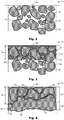
- FIG. 2 shows a schematic cross-sectional view of a portion of a ceramic part 1a in the brown state.
- the ceramic part 1a comprises a multiplicity of ceramic particles 2a, for example of zirconium oxide, which are bonded together in the brown state with the binder remaining low in adhesion.
- the particles 2a may have particle sizes of, for example, 100-300 nm or an average particle size of 250 nm. Between the ceramic particles 2a are formed inside and intermediate spaces 3a. Through the interstices 3a, the ceramic part 1a has at least partially a certain porosity.
- the open porous structure was created by the degradation of the binder polymer matrix during the transformation of the green body into the brown body.
- the porosity is dependent on the proportion of the previously present binder polymer matrix in the green body.
- the ceramic part 1a has a surface 4a.
- FIG. 3 shows the in FIG. 2 shown portion of the ceramic part 1a in an analogous schematic cross-sectional view including an introduced dispersion as an additive 10 with nanoparticles as a filler material 11a, which are finely distributed as a disperse phase in a transport substance 12 as a dispersion medium.
- the dispersion 10 with the nanoparticles 11a may, for example, have penetrated into the ceramic part 1a up to a penetration depth d a , that is to say the intermediate spaces 3a between the particles 2a.
- the nanoparticles 11a are at least partially introduced into the ceramic part 1a and can at least partially wet its surface 4a.
- the in FIG. 3 shown state represents the initial situation of the sintering, wherein between the ceramic particles 2a is a slight caused by residual binder remaining after debinding adhesion.
- additional materials 11a may be present instead of dispersed nanoparticles in additive 10 in the form of other substances in a dissolved state in a solvent.
- the dispersion 10 would be considered as a solution, the nanoparticles 11a as a solute and the transport substance 12 as a solvent.
- Dissolved substances may include salts, for example metal salts, such as sulfates, acetates, chlorides or the like, wherein appropriate organic or inorganic solvents are to be selected for each substance to be dissolved.
- the solvent may be evaporated, leaving the salt in the interstices 3a.
- the salt can in turn be dissociated by heat and / or further converted by the addition of additional reactants.
- Remaining metal oxides can be sintered and / or reduced, for example in the context of redox reactions.
- the metals can be selected according to the respective requirements.
- metals or their salts do not evaporate themselves at the respective sintering temperatures but remain at the desired location.
- metals for example, earth, transition and / or noble metals may be used, such as aluminum, iron, nickel, tungsten, gallium, tin, titanium, cobalt, copper, silver, gold, platinum, etc. and alloys thereof. It may be advantageous if the melting point of the respective metal or alloy is below the sintering temperature and the boiling point is above the sintering temperature.
- FIG. 4 shows a schematic cross-sectional view of a portion of a sintered ceramic part 1 a, which is formed from the ceramic part 1 a in the brown state including additive 10 received therein.
- the residual binder and the transport substance 12 are thermally decomposed or gasified and expelled at the first Aufmorerampe in the sintering furnace.
- the remaining porosity is gradually closed by raising the temperature to sintering temperature and diffusion at the surfaces of the boundaries of the ceramic particles.
- a compaction of the particles 2a to the annealing of the interspaces 3a or pores takes place in a solid phase well below the melting temperature of the ceramic material.
- the final density after sintering is 96-100%.
- a rearrangement of the particles 2 a causes.
- the particle rearrangement is followed by contact formation between the particles 2a.
- contact pads 5b between the particles 2a initially grow in a phase of contact growth.
- Contact growth is followed by particle growth, also called grain growth.
- the sintered ceramic part 1b is provided with sintered ceramic particles 2b, as shown in FIG FIG. 4 is shown.
- an undoped region 20 and a doped region 21 are present after sintering.
- the sintered ceramic particles 2b are at least partially not directly but separated from each other by a mitgesintertes additional material 10b, which at least partially a surface 4b of the sintered ceramic part 1 b can form.
- One of the thicknesses of the doped region 21 corresponds essentially to an average penetration depth d b of the sintered filler material 11b measured perpendicularly from the surface 4b.
- the inventive method is not limited to the production of the technical ceramic components described here, but can be used for the production of any ceramic components.
- components for example, parts of medical implants, such as dental implants come into question.
- additives 10 may contain the respective requirements according to additional materials 11 a in the inserted state from which additional materials 11 b are formed in co-sintered state, with 12 transport substances help the additional materials 11 a, 11 b
- penetration depths d a in the brown state or penetration depth d b in the co-sintered state are to be deposited in order to provide undoped regions 20 and doped regions 21.
- additives 10 suspensions dispersions and / or emulsions can be used.
- the additional materials may be ceramic and / or non-ceramic nature.
Landscapes
- Chemical & Material Sciences (AREA)
- Engineering & Computer Science (AREA)
- Ceramic Engineering (AREA)
- Manufacturing & Machinery (AREA)
- Materials Engineering (AREA)
- Structural Engineering (AREA)
- Organic Chemistry (AREA)
- Inorganic Chemistry (AREA)
- Composite Materials (AREA)
- Compositions Of Oxide Ceramics (AREA)
Abstract
Description
- Die Erfindung betrifft ein Verfahren zur Herstellung von Keramikteilen gemäss unabhängigem Anspruch 1 sowie eine Vorrichtung gemäss Anspruch 15.
- Technische Keramiken haben sich wegen ihrer vorteilhaften Materialeigenschaften für viele Anwendungen etabliert. Je nach verwendetem Keramikmaterial lassen sich Eigenschaften erhalten, die mit anderen Werkstoffen wie Metallen und Polymeren in dieser Art und Kombination nicht möglich wären. Vorteilhafte Eigenschaften verschiedener Keramikmaterialien sind unter anderem hohe mechanische Festigkeit und Steifigkeit, hohe Härte und Abriebfestigkeit, Hitzebeständigkeit, hohe Dielektrizitätskonstanten und gute Biokompatibilität.
- Als beispielhafte Beschreibung der Anwendung technischer Keramik für Getriebebauteile, der damit verbundenen Vorteile und eines möglichen Herstellungsprozesses wird verwiesen auf: Zimmermann, Dirk; Keramische Bauteile für hochbeanspruchte Kleinantriebe; in: Antriebstechnik, F&M, 105 (1997) 4, Carl Hanser Verlag, München, 1997, S. 217-220; sowie auf: Zimmermann, Dirk; Keramik in Antrieben; in: at - Aktuelle Technik, 2/2002, B+L Verlags AG, Schlieren, 2002, S.26-28.
- Ferner beschreibt die
US2001053937A ein Verfahren zur Herstellung von Knochenersatzmaterial mit steifem durchgängigem keramischem Stützwerk, wobei zunächst zur Erzeugung eines Schlickers aus Keramikpulver, beispielsweise Zirkonoxid, einem organischen Binder und Wasser eine Dispersion geformt wird. Dann wird die Stützstruktur eines netzartigen offenporigen organischen Schaums, beispielsweise aus Polyurethan, Polyester, Polyether oder ähnlichem mit dem Schlicker überzogen. Dazu kann der Schaum in den Schlicker getaucht und überschüssiger Schlicker anschliessend entfernt werden. Danach wird der übrige Schlicker getrocknet, die Stützstruktur unterhalb einer Sintertemperatur pyrolisiert und abschliessend das verbleibende keramische Stützwerk gesintert. - Das Verhalten des in der
US2001053937A beschriebenen keramischen Stützwerks bei Einwirkung mechanischer Belastungen soll verbessert werden, indem in dessen Zwischenräume ein osteokonduktives Material sowie zwischen diesem und dem Stützwerk ein bioresorbierbares elastisches Material eingebracht werden. Beim osteokonduktiven Material kann es sich um eine weitere Keramik, wie beispielsweise Kalziumphosphat, handeln, das zusammen mit einem organischen Binder nach dem ersten Sintern und Abkühlen in die Zwischenräume des Stützwerks eingebracht wird. Nach einem weiteren Sinterschritt ist der Binder pyrolisiert und das Kalziumphosphat bildet eine weitere netzartige Struktur, die aufgrund Schwindung beim Sintern vom Stützwerk beabstandet ist. Die Ablösung des Kalziumphosphats vom Stützwerk lässt sich verbessern, indem letzteres vorab mit Paraffin leicht benetzt wird. Der verbleibende Zwischenraum wird mit dem bioresorbierbaren elastischen Material gefüllt, wobei es sich beispielsweise um ein Polymer wie Collagen handeln kann, das von einem Körper resorbiert wird, sobald dessen eigenes Knochenmaterial beim Heilungsprozess in die Zwischenräume hinein wächst. Das osteokonduktive Material kann alternativ auch erst während eines chirurgischen Eingriffs in die Zwischenräume der mit dem bioresorbierbaren, elastischen Material beschichteten Stützstruktur beschichteten Stützwerks eingebracht werden. - Bei aus dem Stand der Technik bekannten Verfahren und Keramikeilen ist von Nachteil, dass sie nur beschränkt den Anforderungen an technische Keramik genügen.
- Aufgabe der Erfindung ist es, vorteilhafte Verfahren zur Herstellung von Keramikteilen zur Verfügung zu stellen. Solche Herstellungsverfahren sollen eine hohe Prozesssicherheit aufweisen und eine gleichbleibende hohe Qualität der Keramik sicherstellen.
- Diese und andere Aufgaben werden gelöst durch ein erfindungsgemässes Herstellungsverfahren gemäss dem unabhängigen Anspruch. Weitere bevorzugte Ausführungsformen sind in den abhängigen Ansprüchen gegeben.
- Die Nachteile aus dem Stand werden durch ein erfindungsgemässes Verfahren insbesondere überwunden, indem zur Herstellung von wenigstens einem gesinterten Keramikteil ein zumindest noch nicht vollständig gesintertes Keramikteil wenigstens bereichsweise mit einem Additiv versehen und anschliessend gesintert wird.
- Dies hat gegenüber dem Stand der Technik den Vorteil, dass die Eigenschaften der nach dem vollständigen Abschluss des Sinterprozesses vorliegenden keramischen Struktur auf bisher nicht bekannte Weise durch das Additiv beeinflusst werden können. So lassen sich zum einen die Festigkeitseigenschaften der Keramik beeinflussen. Zum anderen können weitere physikalische und/oder chemische Eigenschaften der Keramik beeinflusst werden, wie beispielsweise ihre Wärme- und/oder Elektrizitätsleitfähigkeit bzw. chemische Reaktivität oder katalytischen Eigenschaften. Das Additiv kann beispielsweise als Flüssigkeit bzw. in einem im Wesentlichen flüssigen Zustand vorliegen.
- Die erfindungsgemäße Lösung kann durch die folgenden weiteren, jeweils für sich vorteilhaften Ausführungsformen beliebig ergänzt und weiter verbessert werden:
- Gemäss einer ersten weiteren Ausführungsform liegt zumindest ein mit dem Additiv versehener Bereich des Keramikteils vor dem Sintern in einem offenporösem Braunkörperzustand vor. Die offenporöse Struktur des Braunkörpers kann besonders gut dazu genutzt werden, um Additive darin aufzunehmen. Zur Aufnahme der Additive können beispielsweise Kapillarwirkungseffekte genutzt werden, die beim Braunkörper besonders stark auftreten können.
- Gemäss einer weiteren Ausführungsform wird das Additiv in Zwischenräume zwischen keramischen Partikeln des Keramikteils eingebracht. Die keramischen Partikel können im Wesentlichen Korngrössen von beispielsweise 100 bis 300 oder bis 350 nm aufweisen. Zwischen den Partikeln gebildete Zwischenräume können Abmasse in einer ähnlichen Grössenordnung wie die keramischen Partikel besitzen. Durch das Einbringen des Additivs in die Zwischenräume lässt sich eine innige Verbindung zwischen den keramischen Partikeln und dem Additiv oder Teilen davon erzielen.
- Gemäss einer weiteren Ausführungsform bilden wenigstens Teile des Additivs und gesinterte keramische Partikel einen im Wesentlich porenfreien Verbund. Zum einen kann dieser Verbund gewünschte Festigkeitseigenschaften aufweisen, indem er beispielsweise einen den jeweiligen Anforderungen entsprechenden Härtegrad aufweist. Zum anderen kann der Verbund insbesondere spezielle wärme- und/oder elektrizitätsleitende Eigenschaften aufweisen.
- Gemäss einer weiteren Ausführungsform wird eine Oberfläche des Keramikteils zumindest abschnittsweise mit dem Additiv benetzt. Durch die Benetzung kann zumindest abschnittsweise eine besondere Oberfläche am Keramikteil ausgebildet bzw. können Eigenschaften der Oberfläche zumindest abschnittsweise beeinflusst werden. Das Additiv kann dazu genutzt werden, eine Beschichtung des Keramikteils auszubilden.
- Gemäss einer weiteren Ausführungsform wird das Additiv bis zu einer von der Oberfläche aus gemessenen Eindringtiefe in das Keramikteil eingebracht. Somit kann eine mit dem Additiv versehene keramische Schicht bereitgestellt werden. Die Eindringtiefe kann den jeweiligen Anforderungen gemäss eingestellt werden, indem das Keramikteil beispielsweise für eine gewisse Zeitspanne und/oder bis zu einer gewissen Tiefe in das Additiv eingetaucht bzw. diesem ausgesetzt wird.
- Gemäss einer weiteren Ausführungsform werden ein undotierter Bereich des gesinterten Keramikteils, der vor dem Sintern nicht mit dem Additiv versehen worden war, und ein dotierter Bereich, der vor dem Sintern mit dem Additiv versehen worden war, gebildet. Beispielsweise können die Bereiche durchs Sintern ausgebildet bzw. endgültig fixiert werden. Die Bereiche lassen sich durch lokales Auftragen des Additivs und/oder Eintauchen des noch nicht vollständig gesinterten Keramikteils in das Additiv ausbilden. Beispielsweise kann das noch nicht vollständig gesinterte Keramikteil mit dem Additiv bestrichen und/oder besprüht werden. Das Bestreichen und/oder Besprühen kann zonenweise so geschehen, dass gewünschte Muster bzw. geometrische Strukturen ausgebildet werden.
- Gemäss einer weiteren Ausführungsform besitzt der dotierte Bereich eine höhere elektrische und/oder thermische Leitfähigkeit als der undotierte Bereich. Die unterschiedlichen Leitfähigkeiten können sowohl bei der Fertigung als auch bei der späteren Anwendung des gesinterten Keramikteils genutzt werden. Insbesondere kann der undotierte Bereich im Wesentlichen dielektrische bzw. wärmedämmende Eigenschaften aufweisen, wohingegen der dotierte Bereich sich durch eine gewisse elektrische und/oder thermische Leitfähigkeit auszeichnet. Somit sind die beiden Bereiche sensorische und/oder schaltungstechnisch voneinander unterscheidbar. Diese Unterscheidbarkeit kann beispielsweise für Orts- bzw. Positionsbestimmungen des Keramikteils und/oder Verschleissanzeigen benutzt werden. Auch lässt sich das Keramikteil als elektrisches und/oder thermisches Schaltungselement einsetzen.
- Gemäss einer weiteren Ausführungsform wird der dotierte Bereich durch Einbringen elektrischer Energie nach dem Sintern erodiert. Durch das Erodieren lassen sich die mechanischen bzw. tribologischen Eigenschaften des Keramikteils beeinflussen. Insbesondere kann die Oberfläche des Keramikteils gezielt lokal oder grossflächig anforderungsgemäss verändert, beispielsweise aufgerauht werden.
- Gemäss einer weiteren Ausführungsform umfasst das Additiv ein Zusatzmaterial und eine dieses aufnehmende Transportsubstanz. Das Zusatzmaterial und die Transportsubstanz können in ihren Anteilen und ihrer Zusammensetzung beispielsweise gemäss den gewünschten rheologischen Eigenschaften des Additivs und/oder der porösen Eigenschaften des noch nicht vollständig gesinterten Keramikteils eingestellt werden, um deren gewünschtes Zusammenwirken zu erreichen. Verschiedene Zusatzmaterialien und Transportsubstanzen können den jeweiligen Anforderungen beliebig miteinander kombiniert werden.
- Gemäss einer weiteren Ausführungsform wird die Transportsubstanz vorm und/oder beim Sintern wenigstens teilweise verdampft und/oder dissoziiert. Somit lässt sich die Transportsubstanz lediglich als Hilfsmittel zur Anwendung des Zusatzmaterials einsetzen. Beispielsweise kann die Transportsubstanz im Wesentlichen vollständig verdampft und/oder dissoziiert werden, wodurch im Wesentlichen nur noch das Zusatzmaterial aus dem Additiv verbleibt.
- Gemäss einer weiteren Ausführungsform wird das Zusatzmaterial vorm und/oder beim Sintern wenigstens teilweise dissoziiert und/oder reduziert. Es können eine Vielzahl von Zusatzmaterialien eingesetzt werden, die chemische und/oder physikalische Wechselwirkungen miteinander, mit der Transportsubstanz, weiteren Reaktanden und/oder Hilfsmitteln, wie beispielsweise Fluidströmen bzw. elektromagnetischer Strahlung, eingehen können. Somit lässt sich die chemische und/oder physikalische Zusammensetzung des Zusatzmaterials nach der Anwendung beeinflussen.
- Gemäss einer weiteren Ausführungsform umfasst das Zusatzmaterial in der Transportsubstanz dispergierte Nanopartikel und/oder in der Transportsubstanz gelöste Stoffe. Eine offene Porosität Φ eines aus dem Grünling gewonnenen Braunlings kann dazu genutzt werden, Fluide bzw. Emulsionen und Dispersionen zumindest bis zu einer gewissen Tiefe unterhalb der Oberfläche des Braunlings in diesen einzubringen. Mittels der Emulsionen und Dispersionen können Partikel bzw. Nanopartikel in den Braunling eingebracht und mitgesintert werden. Die Partikel sollten zu einem Grad kleiner sein als die Poren des Braunlings, der es ihnen ermöglicht, in die Poren einzudringen. Dementsprechend werden hierfür sogenannte Nanopartikel verwendet, deren Durchmesser in der Regel zwischen 1 und 100 nm liegt, vorzugsweise im Bereich von 5 bis 10 nm.
- Durch die eingebrachten Nanopartikel kann das Gefüge und/oder die Festigkeit des Keramikteils zumindest lokal oder oberflächlich beeinflusst werden. Indem die Partikelgrössen der eingebrachten Nanopartikel untereinander und/oder von den Partikelgrössen der keramischen Rohmasse abweichen, können die gesamten mechanischen Eigenschaften der Keramik beeinflusst werden.
- Des Weiteren können eingebrachte Nanopartikel in den von ihnen infiltrierten Bereichen des Keramikteils zur Beeinflussung der elektrischen und/oder thermischen Leitfähigkeit eingesetzt werden. Beispielsweise können andere Keramiken, Metalle und/oder anorganische Substanzen, wie z.B. Silizium, Siliziumoxyd und/oder Kohlenstoff als Nanopartikel in das Keramikteil eingebracht werden, wodurch sich das Keramikteil zumindest abschnittsweise sozusagen dotieren lässt.
- In den Braunling eingebrachte und mitgesinterte leitfähige Partikel können dazu genutzt werden, entsprechend lokal begrenzt elektrische Energie in das Keramikteil einzubringen. Zwischen den leitfähigen Partikeln werden Kurzschlüsse erzeugt. Im Bereich dieser Kurzschlüsse wird das Keramikmaterial erodiert und somit geschwächt, wodurch sich beispielsweise, wie schon oben erwähnt, Sollbruchstellen oder Verschleissanzeigen realisieren lassen.
- Alternativ oder zusätzlich können die in Lösung befindlichen Zusatzmaterialien bzw. Stoffe durch ein Verdampfen des Lösungsmittels am und/oder im Keramikteil abgelagert werden. Beispielsweise können diese Stoffe als Salze vorliegen. Auch können den jeweiligen Anforderungen gemäss Stoffgemische eingesetzt werden.
- Gemäss einer weiteren Ausführungsform werden bzw. wird das Zusatzmaterial und/oder daraus gewonnener Zusatzstoff mitgesintert. Somit können Zusatzmaterial und/oder Zusatzstoff eine innige Verbindung mit dem keramischen Material eingehen. Insbesondere können Zusatzmaterial und/oder Zusatzstoff Zwischenräume zwischen keramischen Partikeln aus- bzw. auffüllen.
- Zum besseren Verständnis der vorliegenden Erfindung wird nachfolgend auf die Zeichnungen Bezug genommen. Diese zeigen lediglich Ausführungsbeispiele des Erfindungsgegenstands.
- Figur 1
- zeigt schematisch die einzelnen Schritte eines Herstellungsverfahrens für Keramikteile.
- Figur 2
- zeigt eine schematische Querschnittsansicht eines Abschnittes eines Keramikteils im Braunzustand.
- Figur 3
- zeigt den in
Figur 1 gezeigten Abschnitt des Keramikteils in einer analogen schematischen Querschnittsansicht samt einer eingebrachten Dispersion als Additiv. - Figur 4
- zeigt eine schematische Querschnittsansicht eines Abschnittes eines gesinterten Keramikteils, das aus dem Keramikteil im Braunzustand samt darin aufgenommenem Additiv gebildet ist.
- Ein vorteilhaftes Herstellungsverfahren für technische Keramikteile ist in
Figur 1 dargestellt. In einem ersten Schritt S1 wird eine spritzgussfähige Rohmasse hergestellt, indem ein pulverförmiges keramisches Ausgangsmaterial mit einem geeigneten thermoplastischen polymeren Bindermaterial vermischt wird. - In einem Urform-Schritt S2, S3 und/oder S4 wird mit geeigneten Spritzguss-, 3D-Druck- bzw. Extrusionswerkzeugen die erhitzte Rohmasse in die gewünschte Form gebracht. Nach dem Abkühlen bzw. Entformen erhält man den sogenannten Grünling, die erste Stufe für den nachfolgenden Herstellungsprozess des Keramikteiles. Der Grünling entspricht in der Form im Wesentlichen dem zukünftigen Keramikteil, während die Dimensionen grösser sind, um die Schrumpfung während des Sinterns auszugleichen.
- In einem dritten Schritt S7 wird bei der sog. Entbinderung mit geeigneten Verfahren aus dem Grünling ein Grossteil der Bindermaterial-Matrix entfernt. Der resultierende sog. Braunling besteht im Wesentlichen nur noch aus dem pulverförmigen Keramikausgangsmaterial, welches durch eine kleine verbleibende Menge an Bindermaterial in der Form gehalten wird.
- In einem vierten Schritt S8 wird schliesslich der Braunling bei hohen Temperaturen gesintert. Der verbleibende Rest an Bindermaterial wird dabei pyrolisiert. Die für die Sinterung gewählte Temperatur verbleibt unterhalb der Schmelztemperatur der Keramik. Das thermodynamische Gesamtsystem verringert seine freie Enthalpie, indem keramisches Material lokal diffundiert und die einzelnen Partikel an den Berührungsstellen zusammenwachsen, was die Grenzflächenenergie senkt. Nach dem Abkühlen resultiert das fertig gesinterte Keramikteil.
- In einem erfindungsgemässen Herstellungsverfahren für Keramikteile wird in einem ersten Schritt S1 eine spritzgussfähige Rohmasse bereitgestellt. Als Keramikrohmaterial dient dabei pulverförmiges tetragonales Zirkonium(IV)oxid bzw. Zirkoniumdioxid (ZrO2, nachfolgend einfach Zirkonoxid). Die tetragonale Kristallphase wird vorteilhaft durch Dotierung mit einigen mol% Yttrium(III)oxid (Y2O3) stabilisiert, beispielsweise 3-8 mol%. Die Zugabe von 3 Mol% Y2O3 führt zu einer metastabilen tetragonalen Phase. Bei sehr hoher mechanischer Belastung entstehen lokale Spannungsspitzen, die zur Bildung von Mikrorissen führen können. Das Spannungsfeld an der Rissspitze erzeugt die Umwandlung von der tetragonalen zur monoklinen Phase. Durch die dabei entstehende Volumenzunahme werden die Risse verdichtet und der Rissfortschritt ist gebremst. Häufig wird auch eine kleine Menge 0,2-0,3 % Aluminiumoxid zugegeben, was zusätzlich nochmals eine Erhöhung der mechanischen Eigenschaften bewirkt. Die mittlere Korngrösse beträgt beispielsweise ca. 300 nm und sollte sich insbesondere bei Zirkonoxid zwischen 250 und 350nm bewegen bzw. möglichst homogen sein, da sonst Festigkeitsprobleme auftreten können.
- Zirkonoxid weist eine hohe Härte in Kombination mit hoher Elastizität und hoher Biegebruchfestigkeit auf. Dieses keramische Material ist deshalb sehr gut geeignet beispielsweise für bewegliche Bauteile, die unter hohen Belastungen während langer Zeit wartungsfrei und präzise funktionieren sollen, beispielsweise Zahnräder in miniaturisierten Getrieben. Auch für medizinische Implantate, wie beispielsweise Zahnimplantate, welche mit dem Knochengewebe verwachsen sollen, ist Zirkonoxid aufgrund seiner sehr guten Biokompatibilität ein sehr vorteilhaftes Material.
- Als thermoplastisches Bindermaterial wird homopolymeres Polyoxymethylen (POM-H) verwendet. Da für die spätere Verwendung die bei POM übliche Säurestabilisation nicht vorteilhaft ist, wird auf eine Veretherung bzw. Veresterung der Polymer-Endguppen verzichtet. Der Schmelzpunkt von POM-H beträgt ca. 175-178 °C.
- Das pulverförmige Zirkonoxid wird mit geeigneten Geräten mit dem thermoplastischen Binderpolymer homogen gemischt, so dass eine granulatförmige Rohmasse entsteht, die beispielsweise unter dem Produktnamen Catamold® von der Firma BASF vertrieben wird. Zu Herstellung der Rohmasse werden die Bestandteile unter Wärmeeinwirkung in Kneteranlagen homogen vermischt und anschliessend weiter homogenisiert. Entsprechende Technologien sind dem Fachmann aus der Herstellung von mit Füllstoffen beladenen Spritzgussrohpolymeren bekannt. Am Ende des Prozesses resultiert ein ThermoplastGranulat, wie es üblicherweise beim Spritzgiessen oder Extrudieren als Ausgangsmaterial verwendet wird, oder Thermoplast-Filamente, wie sie üblicherweise beim 3D-Druck verwendet werden.
- Das Rohgranulat wird anschliessend in einem nächsten Schritt S2 als Urformschritt mit geeigneten Thermoplast-Spritzgussmaschinen verarbeitet, in der das Bindermaterial aufgeschmolzen wird. Die nun wieder plastische, homogene Rohmasse wird unter hohem Druck (mehrere hundert bar) in entsprechende Spritzgusswerkzeuge gespritzt, wo die Masse in der gewünschten Form erstarrt. Sämtliche Teile der Spritzgusseinheit, die mit der Spritzgussmasse in Berührung kommen, wie z.B. Schnecke, Zylinder, Düse und Rückstromsperre, sind an die aufgrund der enthaltenen Keramikpartikel relativ hohe Abrasivität der Spritzgussmasse anzupassen. Dazu können diese Teile beispielsweise pulvermetallurgisch behandelt sein, um widerstandsfähige Hartmetalloberflächen aufzuweisen.
- Nach dem Entformen und Auskühlen der Spritzgussteile können diese direkt als Grünlinge im Entbinderungsschritt S7 weiterverarbeitet werden, oder einer üblichen Nachbearbeitung unterzogen werden, beispielsweise der Entfernung des Angusses. Analog zu Kunststoffteilen kann der Anguss aufgearbeitet und ein weiteres Mal verwendet werden.
- Es ist jedoch in einer alternativen Variante des erfindungsgemässen Verfahrens auch möglich, die Grünlinge einem weiteren formgebenden Schritt S5 zu unterziehen, beispielsweise Fräsen, Bohren, Schleifen oder Drehen.
- Alternativ oder zusätzlich kann auch die Oberfläche des Grünlings bearbeitet werden. Ein solcher optionaler Arbeitsschritt S6 wird weiter unten noch beschrieben.
- Als weitere Alternative oder zusätzliche Möglichkeit kann in wenigstens einem Vorbearbeitungsschritt S5' und/oder S6' die Form bzw. Oberfläche eines Körpers im Grünzustand noch während, beispielsweise zum Abschluss oder direkt nach dem Urformschritt S2, S2, S4 beeinflusst werden. So ist denkbar, im Vorbearbeitungsschritt S5', S6' die Form eines im Spritzguss S2 erzeugten Grünkörpers in seiner Spritzgussform zu beeinflussen, indem beispielsweise durch sog. "In-mold-closing" verschiedene Grünkörperabschnitte vor dem Auswurf aus dem Werkzeug zu einem Grünkörper zusammengeführt werden. Im Rahmen eines 3D-Druck-Schrittes S3 kann innerhalb eines Vorbearbeitungsschritts S5', S6' ein Abschnitt an einen Grünkörper angeformt oder verschiedene Grünkörper miteinander verbunden werden, der durch ein anderes Urformverfahren erzeugt wurden. Ein durch Extrusion gewonnener Grünkörperstrang bzw. ein Grünkörperprofil kann beim Vorberarbeitungsschritt S5', S6' zum Beispiel vereinzelt werden. Generell kann die Oberfläche während des wenigstens einen Vorbearbeitungschrittes S5', S6' beliebig verändert bzw. bearbeitet werden.
- Bei erfindungsgemässen Verfahren beruht die Entbinderung auf einem kontrollierten, säuregestarteten katalytischen Abbau des Bindermaterials POM-H in einem Temperaturbereich zwischen 90 bis 120 °C, bevorzugt bei 110°C, wenn das schon oben erwähnte Catamold® verwendet wird. Zirkonoxid hingegen ist gegenüber den meisten Säuren stabil. Beim Entbinderungsprozess werden die Polymerketten von den Enden her depolymerisiert und zu gasförmigem Formaldehyd abgebaut. Die vorteilhaft ebenfalls gasförmige Säure wirkt dabei von der Oberfläche des Grünlings her und diffundiert durch die offene poröse Struktur, die durch den Abbau der Binderpolymer-Matrix allmählich entsteht, ins Innere. Die beim säuregestartetem katalytischen Abbau entstehenden gasförmigen Formaldehyd-Monomere wiederum diffundieren durch die poröse Struktur nach aussen.
- Der Entbinderungsprozess erfolgt somit kontinuierlich von aussen nach innen mit einer von der beigegebenen Säuremenge abhängigen Geschwindigkeit von ca. 0.1 bis 0.8 mm/h, insbesondere von 0.4 bis 0.6 mm/h. Eine Erhöhung der Säuremenge beschleunigt zwar den Entbinderungsprozess, der dadurch jedoch ungleichmässig werden kann, was wiederum problematisch sein kann.
- Die Entbinderung wird, abhängig von der Dimensionierung der zu entbindernden Teile, so lange durchgeführt, bis die Bindermatrix über das gesamte Volumen des Werkteils soweit abgebaut ist, dass nur noch ein geringer Rest verbleibt (beispielsweise 0.3 - 0.5 Gew.% der ursprünglichen Bindermatrix). Es resultiert der im Wesentlichen nur noch aus Zirkonoxid-Partikeln bestehende Braunling. Der verbleibende kleine Rest der Bindermatrix von ca. 0.3 - 0.5 % dient der mechanischen Stabilisierung des Braunlings. Die restliche Bindermatrix wird im darauffolgenden Schritt der Sinterung S8 schon bei wenigen hundert °C beim Erwärmen des Braunlings auf Sintertemperatur vollständig pyrolisiert.
- Die Entbinderung erfolgt bei erfindungsgemässen Verfahren bei erhöhter Temperatur und Normaldruck unter Verwendung von Salpetersäure als den Entbinderungsprozess startende Säure. Die Grünlinge werden in einen geeigneten Ofen transferiert und auf die vorgesehen Temperatur erhitzt. Bei einem erfindungsgemässen Verfahren liegt dabei die Temperatur in einem Bereich von 90 bis 110 °C und besonders vorteilhaft bei 110 °C.
- Nach dem Erreichen der Prozesstemperatur wird eine gewisse Menge an Salpetersäure in den Ofen gegeben, die bei diesen Temperaturen in den dampfförmigen Zustand übergeht. Die Verweildauer hängt von der Geometrie der Werkteile ab.
- Vorteilhaft wird aus dem Ofen austretendes Gas einer Reinigung zugeführt, um Salpetersäure und Formaldehyd aufzufangen. Entsprechende Technologien sind dem Fachmann bekannt, beispielsweise durch Abfackeln zu CO2 und H2O oder durch Auskondensation und Gaswäsche.
- Nach dem Entbindern werden die Braunlinge abgekühlt und für die nachfolgende Sinterung zwischengelagert.
- Bei der Sinterung verbacken die einzelnen Partikeloberflächen des Keramikmaterials miteinander. In einem ersten Stadium lagern sich die einzelnen Partikel um und durch Materialdiffusion erhöht sich die Kontaktfläche, was die Grenzflächenenergie erniedrigt. In einem zweiten Stadium wachsen die einzelnen Partikel weiter zusammen und bilden sog. Hälse. Es bilden sich Korngrenzen. Im dritten Stadium wachsen die Körner, und das Porenkanalsystem wird reduziert. Während der Sinterung schrumpft das Werkstück und die Dichte steigt.
- Die Sinterung von Zirkonoxid erfolgt in einem geeigneten Sinterofen, bei Temperaturen weit unterhalb der Phasenübergangstemperatur von der tetragonalen Kristallphase in die kubische Kristallphase (2370 °C bei reinem Zirkonoxid), und damit natürlich auch unterhalb der Schmelztemperatur (2690 °C). Bei einem erfindungsgemässen Verfahren liegt die Sintertemperatur in einem Bereich von 1350 bis 1550 °C, und vorteilhaft in einem Bereich von 1400 bis 1480 °C, insbesondere bei 1450 °C. Für ein möglichst feines Gefüge des Keramikmaterials werden eher niedrige Sintertemperaturen im unteren Bereich der genannten Temperaturspanne gewählt. Sintertemperaturen im oberen Bereich der Temperaturspanne erhöhen hingegen die Dichte und Korngrösse des Keramikmaterials, wodurch dessen Elastizität und Festigkeit abnehmen.
- Der gesamte Sintervorgang dauert bei Zirkonoxid in Abhängigkeit von gewählter Temperatur und Bauteilgrösse ca. 24 bis 36 Stunden. Nach der Sinterung werden die Keramikteile langsam abgekühlt. Sie sind dann in ihrer Urform erstellt, mechanisch fest und ihre Oberfläche ist geschlossen. Durch den Sinterungsprozess unterliegen die Teile im Vergleich zum Grünling einer Schwindung von linear ca. 22% mit einem Toleranzbereich von ±0.3%. Die Schwindung beruht darauf, dass die nach Auslösen des Binders im Braunling vorhandenen Hohlräume zusammenschrumpfen.
- In einer besonders vorteilhaften Variante eines erfindungsgemässen Verfahrens werden der Entbinderungsschritt und der Sinterungsschritt im gleichen Ofen durchgeführt, ohne dass dazwischen der Braunling abgekühlt, zwischengelagert und wieder erhitzt werden muss. Neben der dadurch resultierenden Energieersparnis und Reduktion des Arbeitsaufwands hat ein solches Vorgehen den Vorteil, dass mechanische Belastungen des Werkteils beim Abkühlen und Aufwärmen vermieden werden, und die sehr empfindlichen Braunlinge nicht durch fehlerhafte Behandlung beschädigt werden können.
- Ein weiterer Vorteil liegt darin, dass ein solcher Ofen derart gebaut werden kann, dass er alle Schritte vom Grünling bis zum fertig gesinterten Keramikteil automatisch durchführen kann. Ein derartiger Ofen mit vergleichsweise kleinem Ladevolumen kann beispielsweise in einer Werkstatt zur Herstellung von Implantaten eingesetzt werden.
- Es ist jedoch in einer alternativen Variante des erfindungsgemässen Verfahrens auch möglich, die Keramikteile nach dem Schritt S8 des Sinterns einem zusätzlichen formgebenden Schritt S9 zu unterziehen, beispielsweise Fräsen, Bohren, Schleifen oder Drehen.
- Alternativ oder zusätzlich kann auch die Oberfläche der Keramikteile bearbeitet werden. Ein solcher optionaler Arbeitsschritt S10 wird weiter unten noch beschrieben.
- In einer weiteren vorteilhaften Variante eines erfindungsgemässen Verfahrens wird als Urformschritt, also als grundlegender formgebender Schritt zur Herstellung des Grünlings, anstatt des Spritzgussverfahrens S2 ein dreidimensionales Druckverfahren (3D-Druck) S3 eingesetzt.
- In der Anmeldung der Anmelderin mit dem Titel "Freiform-Keramikbauteile", die am gleichen Tag wie diese Anmeldung angemeldet worden ist, und deren Offenbarungsgehalt hiermit in seiner Gesamtheit durch Referenz in die Beschreibung mit aufgenommen wird, wird ein solches vorteilhaftes Verfahren zur Herstellung von Grünlingen offenbart.
- Mit einem geeigneten 3D-Druckersystem werden die Grünlinge additiv aus der thermoplastischen Rohmasse aufgebaut. Die Rohmasse besteht neben dem pulverförmigen, yttriumstabilisierten Zirkonoxid vorteilhaft wiederum aus POM-H als thermoplastischem Binderpolymer. Das thermoplastische Rohmaterial kann mit einem geeigneten Druckkopf, beispielsweise in Form einer Düse, punkt- oder streifenweise in flüssiger oder plastischer Form auf den im Aufbau befindlichen Grünling appliziert werden (sog. Fused Deposition Modeling). Um bei auskragenden Formen die notwendigen Stützstrukturen aufzubauen, kann ein zweites Material verwendet werden, beispielsweise ein in Lösungsmitteln leicht lösliches Polymer, dass anschliessend an den 3D-Druck des Grünlings aufgelöst werden kann, so dass nur das Materials des Grünlings verbleibt. Alternativ kann auch Bindermaterial ohne Zirkonoxid verwendet werden, welches bei der Entbinderung des Grünlings restlos abgebaut bzw. entfernt wird.
- Alternativ kann das Rohmaterial als feines, rieselfähiges Pulver bereitgestellt und schichtweise durch Laserlicht aufgeschmolzen werden (sog. selektives Laserschmelzen), oder gesintert (sog. selektives Lasersintern), wobei sich hier der Begriff "Sintern" auf die Thermoplastpartikel bezieht, und nicht etwas auf das nachfolgende Sintern der Vielzahl an Keramikpartikeln innerhalb der Thermoplastpartikel. Um die Schmelztemperatur zu senken, kann die Kettenlänge des POM-H Polymers kürzer gewählt werden als bei einer Rohmasse für ein Spritzgussverfahren.
- Der Vorteil von 3D-Druck bei der Anfertigung von Grünlingen liegt bei der Fertigung von Einzelteilen oder Kleinserien. Insbesondere lassen sich auf diese Weise aufgrund spezifischer 3D-Daten grössere Keramik-Implantate anfertigen, beispielsweise für die rekonstruktive Gesichtschirurgie.
- Die auf diese Weise angefertigten Grünlinge können direkt mit den Schritten S7 (Entbinderung) und S8 (Sinterung) zum fertigen Keramikteil weiterverarbeitet werden. Alternativ kann vor der Entbinderung noch ein sekundärer Formgebungsschritt S5 erfolgen, und/oder eine Oberflächenbehandlung S6.
- In einer weiteren vorteilhaften Variante eines erfindungsgemässen Verfahrens wird als Urformschritt zur Herstellung des Grünlings anstatt des Spritzgussverfahrens S2 oder des dreidimensionalen Druckverfahren S3 ein Extrusionsverfahren S4 eingesetzt. Der entsprechende Herstellungsprozess ist schematisch in
Figur 3 dargestellt. - Ein Vorteil der Extrusion bei der Anfertigung von Grünlingen liegt bei der Fertigung von Kleinserien mit Stückzahlen, für die einerseits zu gering sind, als dass sich die Herstellung eines Spritzgusswerkzeugs lohnen würde, und die andererseits zu gross für die wirtschaftliche Anwendung eines 3D-Druckverfahrens sind. Insbesondere lassen sich durch Extrusion kleine gleichförmige Bauteile, wie beispielsweise Zahnräder oder Achsen, anfertigen.
- Die Form des Grünlings kann den jeweiligen Anforderungen gemäss zumindest abschnittsweise beim und/oder nach dem Ent- bzw. Ausformen im Rahmen wenigstens eines sekundären Formgebungsschrittes S5 manipuliert werden.
- Die Manipulation kann insbesondere erforderlich sein, wenn der Grünling durch Schwindungsprozesse beim Abkühlen einen Verzug aufweist. Dies kann beispielsweise der Fall sein, wenn der Grünling ein Vielzahl von auf einem Träger bzw. einer Trägerplatte angeordneten Bauteilen umfasst. Wenn die Bauteile entlang einer Längsseite des Trägers oder auf einer Flachseite der Trägerplatte angeordnet sind, so kann es erforderlich sein, einen Verzug des Trägers bzw. der Trägerplatte auszugleichen.
- Der Ausgleich kann durch Zerspanen, beispielsweise Planschleifen der Bauteile, erfolgen. Um den Ausgleich zu erzielen können Abschnitte des Bauteile und/oder des Trägers abgenommen werden. Je nach Anforderung ist insbesondere bei relativ kleinen Bauteilen die Zerspanung sehr präzise, beispielsweise in Bereichen von 2 bis 10 µm maximalen Materialabtrags durchzuführen.
- Des Weiteren kann die Manipulation erforderlich sein, wenn der Grünling durch Extrusion geformt ist. So wird bei der Extrusion in der Regel ein Grünkörperstrang bzw. -profil geformt, das eine Vielzahl noch zu vereinzelnder Bauteile im Grünzustand umfasst. Die Vereinzelung kann beispielsweise durch ein regelmässiges Abtrennen extrudierter Grünkörper aus dem Strang bzw. Profil erfolgen.
- Da durch Extrusion in der Regel nur Stränge und Profile mit konstantem Querschnitt geformt werden können, sind jegliche an extrudierten Grünkörpern gewünschte Querschnittsveränderungen nachträglich anzubringen. So können am Grünling insbesondere jegliche Art von Vertiefungen, wie beispielsweise Kerben oder Nuten, entlang dessen Aussenumfang angebraucht werden.
- Die Vertiefungen können zum einen durch Zerspanen ausgeformt werden. Zum anderen können die Vertiefungen aufgrund der thermoplastischen Eigenschaften des Grünlings mit Hilfe von Umform-Werkzeugen erzeugt werden, die in die Oberfläche des Grünlings eindringen. Beispielsweise kann ein Eindrücken der Oberfläche erfolgen, solange der Grünling nach dem Extrudieren noch nicht vollständig erkaltet ist, oder das Eindrücken erfolgt am erkalteten Grünkörper mittels eines erwärmten Werkzeugs, beispielsweise eines Stempels.
- Zwar wäre als weitere Alternative eine sekundäre Formgebung am Braunling möglich. Jedoch ist der Braunling im Vergleich zum Grünling oder gesinterten Keramikteil relativ Spröde und zerbrechlich. Der Braunling ist nämlich, wie schon erwähnt, im Wesentlichen nur durch den Verbleibenden Binder zusammengehalten und weist eine vergleichsweise offenporige Struktur auf. Dies erschwert die Bearbeitung des Braunlings.
- Um hier Abhilfe zu schaffen kann der Braunling zumindest oberflächlich in ein Füllmaterial, beispielsweise ein flüssiges thermoplastisches Polymer getaucht werden. Das erstarrte Polymer würde zumindest oberflächig die Poren des Braunlings füllen und diesen somit stabilisieren, was dessen sekundäre Formgebung, beispielsweise durch Einspannen sowie Zerspanen vereinfacht. Nach der sekundären Formgebung kann das Füllmaterial in einem weiteren Entbinderungsschritt und/oder beim Sintern pyrolisiert werden. Allerdings ist das Porenverfüllen mit einem gewissen Zeitaufwand verbunden, der sich nachteilig auf den Produktionsablauf bzw. die Produktionsgeschwindigkeit auswirken kann.
- Vorteilhaft wird die Erhöhung der Oberflächenrauhigkeit bereits beim Grünling vorgenommen, da dieser einfacher zu bearbeiten ist. In einer vorteilhaften Variante wird die Oberfläche des Grünlings sandgestrahlt. Da der Grünling eine wesentlich geringere Härte aufweist als das gesinterte Keramikteil, dauert dieser Prozess wesentlich kürzer als beim gesinterten Keramikteil.
- In einer anderen vorteilhaften Variante wird die Oberfläche des Grünlings mit einer Vielzahl von eng fokussierten Laserpulsen bestrahlt, um die Oberfläche punktförmig aufzuschmelzen oder vorzugsweise zu verdampfen und so die gewünschte Rauhigkeit zu erreichen.
- In einer weiteren Ausführungsform werden feine Keramikpartikel der gleichen Art wie die in der Rohmasse, also beispielsweise Zirkonoxid-Partikel, mit geeigneten Verfahren mit einer sehr dünnen Schicht Bindermaterial überzogen. Der Grünling kann nun mit diesen Partikeln beschichtet werden. Beispielsweise können die Grünlinge mit Heissluft oder Infrarot kurzfristig an der Oberfläche soweit erwärmt und die thermoplastische Matrix angeschmolzen werden, dass die binderbeschichteten Partikel daran kleben bleiben, wenn der erwärmte Grünling in eine Kammer mit verwirbeltem Partikelstaub gebracht wird, oder komplett oder zumindest gezielt abschnittsweise in ein Bad von entsprechendem Partikelstaub getaucht wird. Ein derart beschichtetes Keramikteil kann nun mit den bereits beschriebenen Entbinderungsverfahren und Sinterungsverfahren weiter verarbeitet werden. Die anhaftenden Keramikpartikel verbinden sich beim Sintern mit dem Keramikkörper, was zu einer erhöhten Oberflächenrauhigkeit führt.
- Alternativ oder zusätzlich kann die Oberfläche des Grünlings zumindest abschnittsweise geglättet werden. Beispielsweise lassen sich so Unebenheiten auf der Oberfläche des Grünlings beseitigen, die sich aus dem jeweiligen formgebenden Verfahren ergeben können. Derartige Unebenheiten können insbesondere beim 3D-Druck-Verfahren im den Übergängen zwischen den einzelnen gedruckten Schichten entstehen. Um die Unebenheiten zu beseitigen kann beispielsweise ein Gasstoffstrom auf die Oberfläche des (noch thermoplastischen) Grünlings gerichtet werden. Auch kann die Oberfläche des Grünlings geschliffen werden.
- Die nach den oben genannten erfindungsgemässen Verfahren hergestellten Keramikteile können anschliessend weiter nachbearbeitet werden, beispielsweise mittels verschiedener Schleif- und Polierverfahren, Schneidverfahren, Sandstrahlen, Bearbeitung mittels Laser und Glasieren. Ebenfalls möglich sind Nachbearbeitungsverfahren, welche die strukturellen Eigenschaften der Keramik weiter verbessern, beispielsweise Heisspressen oder heiss-isostatisches Pressen. Beim heiss-isostatischen Pressen, dem sogenannten "HiPen", werden Keramikteile bei einem Druck von 2000 bis 3000 bar und annähernd Sintertemperatur an der Oberfläche nachverdichtet. Somit kann die Bruchfestigkeit des Keramikteils um bis zu 25% auf ca. 1300 MPa gesteigert werden.
- Besonders vorteilhafte Nachbearbeitungsverfahren von Keramikteilen sind in der Anmeldung der Anmelderin mit dem Titel "Spezial-Keramikbauteile" offenbart, die am gleichen Tag wie diese Anmeldung angemeldet worden ist, und deren Offenbarungsgehalt hiermit in seiner Gesamtheit durch Referenz in die Beschreibung mit aufgenommen wird.
- In einem solchen Verfahren wird in einem ersten Schritt das Keramikteil in eine Haltemasse zumindest abschnittsweise eingegossen oder eingetaucht- bzw. gedrückt. In einem zweiten Schritt wird ein Teil des Keramikteils zerspant. Die Haltemasse erlaubt es dabei, auch sehr fein strukturierte Keramikteile zu bearbeiten. Die Haltemasse schützt das Keramikteil vor mechanischen Beschädigungen und erlaubt das einfache Einspannen in Haltevorrichtung der Zerspanungsmaschine. In einem dritten Schritt wird die Haltemasse wieder entfernt, beispielsweise durch Auflösen der Haltemasse.
- Vorteilhaft wird als Haltemasse ein lösliches Polymer, beispielsweise ein Harz, ein Zucker und/oder dessen oxidierte und kondensierte Reaktionsprodukte, verwendet. Das zu bearbeitende Keramikteil wird beispielsweise in die geschmolzene Haltemasse eingegossen oder in eine Haltemasseschicht eingedrückt. Der resultierende Block bzw. Verbund wird für den Zerspanungsvorgang in eine Halterung eingespannt. Nach dem Fräsvorgang wird die Haltemasse bzw. deren Polymermatrix mit geeigneten Lösungsmitteln aufgelöst, beispielsweise mit Wasser und/oder Alkohol bzw. Ethanol, einem Aceton-Wasser-Gemisch, einer wässrigen Borax- oder Ammoniaklösung, usw.
- Vorteilhaft wird als Haltemasse ein natürliches Material verwendet, das biologisch abbaubar und physiologisch unbedenklich ist. Neben dem oben genannten Zucker kann als natürliches Harz beispielsweise gereinigter Gummilack verwendet werden. Dieser kann durch ebenfalls unproblematische Lösungsmittel wie Ethanol oder Borax-Lösung gelöst werden und ist mehrfach verwendbar. Alternativ kann auch mit Borax präalkalisierter gereinigter Gummilack verwendet werden, der direkt wasserlöslich ist.
- Bei einer ersten Verfahrensvariante wird ein gemeinsames erweitertes Angussstück in Form eines Trägers bzw. einer Trägerplatte mit einer Mehrzahl von beispielsweise identischen Kleinteilen durch Zerspanen bspw. Schleifen entfernt, so dass schliesslich die vereinzelten Keramikkleinteile resultieren, beispielsweise Keramikzahnräder mit Durchmessern von wenigen Millimetern. Das erweitere Angussstück, welches beispielsweise die Form einer Platte haben kann, erlaubt zum einen beim Spritzgiessen einen homogenen Materialfluss über das gesamten Volumen des späteren Keramikkleinteils, und daraus resultierend entsprechend homogene Materialeigenschaften. Zum anderen werden mechanische Beschädigungen des Grünlings beim Entformen vermieden. Ebenfalls ist das Handling während der nachfolgenden Herstellungsschritte stark vereinfacht.
- In einer anderen Verfahrensvariante wird flächig ein Teil eines im Wesentlichen plattenförmigen Keramikteils zerspant. Die Keramikplatte weist auf der einen Seite der Platte Ausnehmungen oder Vertiefungen auf, wie beispielsweise Sacklöcher oder Schlitze, welche beim flächigen Wegfräsen des Materials auf der anderen Seite der Platte angeschnitten werden. Es resultiert ein Keramikteil mit durchgehenden Löchern oder Schlitzen, die nicht direkt durch entsprechendes Spritzgiessen des Grünlings zu fertigen wären und die ansonsten nur sehr aufwendig durch nachträgliches Bearbeiten einer Keramikplatte mit Bohren oder Schlitzfräsen hergestellt werden könnten.
- Die Oberfläche des gesinterten Keramikteils ergibt sich im Wesentlichen aus den Eigenschaften der Oberfläche des Grünlings bzw. Braunlings. Mit Spritzguss hergestellte Oberflächen sind vergleichsweise glatt. Für gewisse Anwendungen kann es jedoch vorteilhaft sein, die Oberflächenrauhigkeit des Keramikteils zu erhöhen, beispielsweise bei Implantaten, um das stabile Zusammenwachsen mit Knochengewebe zu erleichtern. Üblicherweise wird dazu die Oberfläche des gesinterten Keramikteils durch Sandstrahlen und/oder Ätzen aufgeraut. Zum Ätzen kann beispielsweise Flusssäure verwendet werden.
- Alternativ oder zusätzlich kann die Oberfläche des Keramikteils geglättet werden.
-
Figur 2 zeigt eine schematische Querschnittsansicht eines Abschnittes eines Keramikteils 1a im Braunzustand. Das Keramikteil 1a umfasst eine Vielzahl keramischer Partikel 2a, beispielsweise aus Zirkonoxid, die im Braunzustand unter der geringen Haftung verbleibenden Binders miteinander verbunden sind. Die Partikel 2a können Korngrößen von beispielsweise 100-300 nm bzw. eine mittlere Korngrösse von 250 nm aufweisen. Zwischen den keramischen Partikeln 2a sind Innen- bzw. Zwischenräume 3a gebildet. Durch die Zwischenräume 3a besitzt das Keramikteil 1a zumindest abschnittsweise eine gewisse Porosität. Die offene poröse Struktur ist durch den Abbau der Binderpolymer-Matrix bei der Umwandlung des Grünkörpers in den Braunkörper entstanden. Die Porosität ist dabei abhängig von dem Anteil der zuvor vorhandenen Binderpolymer-Matrix im Grünkörper. Je höher der Anteil der Binderpolymer-Matrix im Grünkörper ist, desto grösser ist die durch dessen Abbau entstehende offene poröse Struktur im Braunling. Des Weiteren weist das Keramikteil 1a eine Oberfläche 4a auf. -
Figur 3 zeigt den inFigur 2 gezeigten Abschnitt des Keramikteils 1a in einer analogen schematischen Querschnittsansicht samt einer eingebrachten Dispersion als Additiv 10 mit Nanopartikeln als ein Zusatzmaterial 11a, die als disperse Phase in einer Transportsubstanz 12 als Dispersionsmedium fein verteilt aufgenommen sind. Die Dispersion 10 mit den Nanopartikeln 11a kann beispielsweise bis zu einer Eindringtiefe da in das Keramikteil 1a, also die Zwischenräume 3a zwischen den Partikeln 2a eingedrungen sein. Die Nanopartikel 11a sind zumindest abschnittsweise in das Keramik Teil 1 a eingebracht und können wenigstens teilweise dessen Oberfläche 4a benetzen. Der inFigur 3 gezeigte Zustand stellt die Ausgangssituation von dem Sintern dar, wobei zwischen den keramischen Partikeln 2a eine geringe durch nach dem Entbindern verbleibenden Restbinder bewirkte Haftung besteht. - Als alternative oder zusätzliche erfindungsgemässe Möglichkeit zur Einbringung von Zusatzmaterialien 11a in den Braunkörper können diese anstatt als dispergierte Nanopartikel im Additiv10 in Form von anderen Stoffen in einem gelöstem Zustand in einem Lösungsmittel vorliegen. In diesem Falle wären die Dispersion 10 als Lösung, die Nanopartikel 11a als gelöster Stoff und die Transportsubstanz 12 als Lösungsmittel zu betrachten.
- Gelöste Stoffe können Salze umfassen, beispielsweise Metallsalze, wie Sulfate, Acetate, Chloride oder Ähnliches, wobei entsprechende organische oder anorganische Lösungsmittel für den jeweils zu lösenden Stoff auszuwählen sind. Das Lösungsmittel kann verdampft werden, wodurch das Salz in den Zwischenräumen 3a verbleibt. Das Salz kann wiederum durch Hitzeinwirkung dissoziiert und/oder durch Beigabe zusätzlicher Reaktanden weiter umgewandelt werden. Verbleibende Metall-Oxide können mitgesintert und/oder reduziert werden, beispielsweise im Rahmen von Redox-Reaktionen. Die Metalle können den jeweiligen Anforderungen gemäss ausgewählt werden.
- Insbesondere ist darauf zu achten, dass die Metalle oder ihre Salze bei den jeweiligen Sintertemperaturen nicht selber verdampfen, sondern am gewünschten Ort verbleiben. Als Metalle können beispielsweise Erd-, Übergangs- und/oder Edelmetalle verwendet werden, wie Aluminium, Eisen, Nickel, Wolfram, Gallium, Zinn, Titan, Kobalt, Kupfer, Silber, Gold, Platin, etc. sowie Legierungen daraus. Es kann von Vorteil sein, wenn der Schmelzpunkt des jeweiligen Metalls bzw. der Legierung unterhalb der Sintertemperatur und der Siedepunkt oberhalb der Sintertemperatur liegt.
-
Figur 4 zeigt eine schematische Querschnittsansicht eines Abschnittes eines gesinterten Keramikteils 1a, das aus dem Keramikteil 1a im Braunzustand samt darin aufgenommenem Additiv 10 gebildet ist. Der Restbinder und die Transportsubstanz 12 werden bei der ersten Aufheizrampe im Sinterofen thermisch zersetzt bzw. vergast und ausgetrieben. Die verbleibende Porosität wird allmählich durch Steigerung der Temperatur bis auf Sintertemperatur und Diffusion an den Oberflächen der Grenzen der keramischen Partikel geschlossen. Ein Verdichten der Partikel 2a bis zur Ausheilung der Zwischenräume 3a bzw. Poren findet in einer festen Phase deutlich unterhalb der Schmelztemperatur des keramischen Werkstoffes statt. Die Enddichte nach dem Sintervorgang beträgt 96-100%. - Dabei tritt eine Verdichtung des Keramikteils 1a im Braunzustand unter konstanter Volumenreduzierung in allen drei Raumrichtungen auf, womit ein räumlicher Schwund mit einem Faktor von ca. 1,05 bis max. 1,3 gegenüber dem gesinterten Keramikteil 1 b einhergeht.
- Durch das Sintern wird beginnend bei der in
Figur 3 gezeigten Ausgangssituation zunächst eine Umordnung der Partikel 2a bewirkt. An die Partikelumordnung schliesst sich eine Kontaktbildung zwischen den Partikeln 2a an. Dann wachsen Kontaktstellen 5b zwischen den Partikeln 2a zunächst in einer Phase des Kontaktwachstums. An das Kontaktwachstum schliesst sich ein Partikelwachstum, auch genannt Kornwachstum, an. Nach weiterem Kornwachstum und einem Porenausheilen liegt das gesinterte Keramikteil 1 b mit gesinterten keramischen Partikeln 2b vor, wie es inFigur 4 gezeigt ist. - Bei einem erfindungsgemäss zumindest abschnittsweise mit dem Additiv 10 versehenen Keramikteil 1a, 1 b liegen nach dem Sintern ein undotierter Bereich 20 und ein dotierter Bereich 21 vor. Im dotierten Bereich 21 sind die gesinterten keramischen Partikel 2b zumindest teilweise nicht direkt, sondern durch ein mitgesintertes Zusatzmaterial 10b voneinander getrennt bzw. miteinander verbunden, das wenigstens abschnittsweise eine Oberfläche 4b des gesinterten Keramikteils 1 b ausbilden kann. Eine der Stärke des dotierten Bereichs 21 entspricht Wesentlichen einer senkrecht von der Oberfläche 4b aus gemessenen durchschnittlichen Eindringtiefe db des mitgesinterten Zusatzmaterials 11b.
- Das erfindungsgemässe Verfahren ist nicht auf die Herstellung der hier beschriebenen technischen Keramikbauteile beschränkt, sondern kann zur Herstellung beliebiger Bauteile aus Keramik verwendet werden. Als Bauteile kommen beispielsweise Teile von medizinischen Implantaten, wie Zahnimplantaten in Frage.
- Im Rahmen des Erfindungsgedankens sind Abweichungen von den oben beschriebenen Ausführungsbeispielen möglich. So kann auf Basis eines Keramikteils 1 a im Braunzustand den jeweiligen Anforderungen gemäss ein gesintertes Keramikteil 1 b hergestellt werden, wobei aus den keramischen Partikeln 2a im Braunzustand wie gewünscht gesinterte keramische Partikel 2b gebildet und aus Zwischenräumen 3a im Braunzustand Zwischenräume 3b zwischen im gesinterten Zustand sowie aus Oberflächen 4a im Braunzustand Oberfläche 4b im gesinterten Zustand erzeug werden.
- Erfindungsgemäss in beliebiger Anzahl und Abfolge in die Zwischenräume 3a, 3b eingebrachte Additive 10 können den jeweiligen Anforderungen gemäss Zusatzmaterialien 11 a im eingebrachten Zustand enthalten, aus denen Zusatzmaterialien 11 b im mitgesinterten Zustand gebildet werden, wobei 12 Transportsubstanzen dabei helfen, die Zusatzmaterialien 11a, 11b in den jeweiligen Anforderungen gemässen Eindringtiefen da im Braunzustand bzw. Eindringtiefen db im mitgesinterten Zustand zu deponieren, um undotierter Bereiche 20 und dotierter Bereiche 21 bereitzustellen. Als Additive 10 können Suspensionen, Dispersionen und/oder Emulsionen eingesetzt werden. Die Zusatzmaterialien können keramische und/oder nicht-keramischer Natur sein.
- Die vorliegende Erfindung ist in ihrem Umfang nicht auf die hier beschriebenen spezifischen Ausführungsformen beschränkt. Vielmehr ergeben sich für den Fachmann aus der Beschreibung und den dazugehörigen Figuren zusätzlich zu den hier offenbarten Beispielen verschiedene weitere Modifikationen der vorliegenden Erfindung, die ebenfalls in den Schutzbereich der Ansprüche fallen. Zusätzlich werden in der Beschreibung verschiedene Referenzen zitiert, deren Offenbarungsgehalt hiermit in deren Gesamtheit durch Referenz in die Beschreibung mit aufgenommen wird.
-
- 1a
- Keramikteil im Braunzustand
- 1b
- gesintertes Keramikteil
- 2a
- keramischer Partikel im Braunzustand
- 2b
- gesinterte keramische Partikel
- 3a
- Zwischenraum zwischen keramischen Partikeln im Braunzustand
- 3b
- Zwischenraum zwischen keramischen Partikeln im gesinterten Zustand
- 4a
- Oberfläche Keramikteil im Braunzustand
- 4b
- Oberfläche Keramikteil im gesinterten Zustand
- 10
- Additiv
- 11a
- Zusatzmaterial im eingebrachten Zustand
- 11b
- Zusatzmaterial im mitgesinterten Zustand
- 12
- Transportsubstanz
- 20
- Undotierter Bereich
- 21
- Dotierter Bereich
- da
- Eindringtiefe des Zusatzmaterials im Braunzustand
- db
- Eindringtiefe des Zusatzmaterials im mitgesinterten Zustand
Claims (15)
- Verfahren zur Herstellung von wenigstens einem gesinterten Keramikteil (1b), wobei ein zumindest noch nicht vollständig gesintertes Keramikteil (1a) wenigstens bereichsweise mit einem Additiv (10) versehen und anschliessend gesintert wird.
- Verfahren nach Anspruch 1, dadurch gekennzeichnet, dass zumindest ein mit dem Additiv (10) versehener Bereich des Keramikteils (1a) vor dem Sintern in einem offenporösem Braunkörperzustand vorliegt.
- Verfahren nach Anspruch 1 oder 2, dadurch gekennzeichnet, dass das Additiv (10) in Zwischenräume (3a) zwischen keramischen Partikeln (2a) des Keramikteils (1a) eingebracht wird.
- Verfahren nach Anspruch 3, dadurch gekennzeichnet, dass wenigstens Teile des Additivs (10) und gesinterte keramische Partikel (3b) einen im Wesentlich porenfreien Verbund bilden.
- Verfahren nach wenigstens einem der Ansprüche 1 bis 4, dadurch gekennzeichnet, dass eine Oberfläche (4a) des Keramikteils zumindest abschnittsweise mit dem Additiv (10) benetzt wird.
- Verfahren nach Anspruch 5, dadurch gekennzeichnet, dass das Additiv (10) bis zu einer von der Oberfläche (4a) aus gemessenen Eindringtiefe (da) in das Keramikteil (1a) eingebracht wird.
- Verfahren nach wenigstens einem der Ansprüche 1 bis 6, dadurch gekennzeichnet, dass ein undotierter Bereich (20) des gesinterten Keramikteils (1 b), der vor dem Sintern nicht mit dem Additiv (10) versehen worden war, und ein dotierter Bereich (21), der vor dem Sintern mit dem Additiv (10) versehen worden war, gebildet werden.
- Verfahren nach Anspruch 7, dadurch gekennzeichnet, dass der dotierte Bereich (21) eine höhere elektrische Leitfähigkeit besitzt als der undotierte Bereich (20).
- Verfahren nach Anspruch 7 oder 8, dadurch gekennzeichnet, dass der dotierte Bereich (21) durch Einbringen elektrischer Energie nach dem Sintern erodiert wird.
- Verfahren nach wenigstens einem der Ansprüche 1 bis 9, dadurch gekennzeichnet, dass das Additiv (10) ein Zusatzmaterial (11a) und eine dieses aufnehmende Transportsubstanz (12) umfasst.
- Verfahren nach Anspruch 10, dadurch gekennzeichnet, dass die Transportsubstanz (12) vorm und/oder beim Sintern wenigstens teilweise verdampft und/oder dissoziiert wird.
- Verfahren nach Anspruch 10 oder 11, dadurch gekennzeichnet, dass das Zusatzmaterial (11a) vorm und/oder beim Sintern wenigstens teilweise dissoziiert und/oder reduziert wird.
- Verfahren nach wenigstens einem der Ansprüche 10 bis 12, dadurch gekennzeichnet, dass das Zusatzmaterial (11 a) in der Transportsubstanz (12) dispergierte Nanopartikel und/oder in der Transportsubstanz (12) gelöste Stoffe umfasst.
- Verfahren nach wenigstens einem der Ansprüche 10 bis 13, dadurch gekennzeichnet, dass das Zusatzmaterial (11 a) und/oder daraus gewonnene Zusatzstoffe mitgesintert werden bzw. wird.
- Vorrichtung zur Herstellung von gesinterten Keramikteilen (1 b) durch ein Verfahren nach wenigstens einem der Ansprüche 1 bis 14.
Applications Claiming Priority (1)
| Application Number | Priority Date | Filing Date | Title |
|---|---|---|---|
| CH01739/15A CH711817A1 (de) | 2015-11-27 | 2015-11-27 | Verfahren und Vorrichtung zur Herstellung von Keramikteilen. |
Publications (2)
| Publication Number | Publication Date |
|---|---|
| EP3173392A1 true EP3173392A1 (de) | 2017-05-31 |
| EP3173392B1 EP3173392B1 (de) | 2021-04-21 |
Family
ID=54707493
Family Applications (1)
| Application Number | Title | Priority Date | Filing Date |
|---|---|---|---|
| EP16200487.3A Active EP3173392B1 (de) | 2015-11-27 | 2016-11-24 | Verfahren zur herstellung von keramikteilen |
Country Status (2)
| Country | Link |
|---|---|
| EP (1) | EP3173392B1 (de) |
| CH (1) | CH711817A1 (de) |
Cited By (1)
| Publication number | Priority date | Publication date | Assignee | Title |
|---|---|---|---|---|
| DE102019120640A1 (de) * | 2019-07-31 | 2021-02-04 | Aesculap Ag | Offenporiger chirurgischer Gefässclip zum Verschluss von Blutgefässen |
Citations (7)
| Publication number | Priority date | Publication date | Assignee | Title |
|---|---|---|---|---|
| WO2000046168A1 (de) * | 1999-02-04 | 2000-08-10 | 3M Espe Ag | Einfärbung von keramiken mittels ionischer oder komplexhaltiger lösungen |
| US20010053937A1 (en) | 1997-10-01 | 2001-12-20 | Johnson James R. | Bone substitutes |
| DE102006062712A1 (de) * | 2006-02-03 | 2007-08-30 | Maxon Motor Gmbh | Implantat und Verfahren zur Herstellung eines Implantats |
| DE102013017193A1 (de) * | 2013-10-16 | 2015-04-16 | Schunk Ingenieurkeramik Gmbh | Verfahren zum Herstellen von Formkörpern aus reaktionsgebundenem, mit Silicium infiltriertem Siliciumcarbid und/oder Borcarbid und so hergestellter Formkörper |
| US20150122147A1 (en) * | 2012-05-15 | 2015-05-07 | Shenzhen Upcera Dental Technology Co., Ltd | Coloring solution for dental zirconia ceramics and method for using the same |
| US20150157430A1 (en) * | 2012-08-03 | 2015-06-11 | 3M Innovative Properties Company | Translucency enhancing solution for zirconia ceramics |
| WO2015168332A2 (en) * | 2014-04-30 | 2015-11-05 | Osseodyne Surgical Solutions, Llc | Osseointegrative surgical implant |
Family Cites Families (1)
| Publication number | Priority date | Publication date | Assignee | Title |
|---|---|---|---|---|
| FR2626270B1 (fr) * | 1988-01-22 | 1992-04-30 | Pechiney Recherche | Procede de cofrittage, de conducteurs en cuivre ou en alliages a base de cuivre et de leur substrat ceramique en cordierite |
-
2015
- 2015-11-27 CH CH01739/15A patent/CH711817A1/de not_active Application Discontinuation
-
2016
- 2016-11-24 EP EP16200487.3A patent/EP3173392B1/de active Active
Patent Citations (7)
| Publication number | Priority date | Publication date | Assignee | Title |
|---|---|---|---|---|
| US20010053937A1 (en) | 1997-10-01 | 2001-12-20 | Johnson James R. | Bone substitutes |
| WO2000046168A1 (de) * | 1999-02-04 | 2000-08-10 | 3M Espe Ag | Einfärbung von keramiken mittels ionischer oder komplexhaltiger lösungen |
| DE102006062712A1 (de) * | 2006-02-03 | 2007-08-30 | Maxon Motor Gmbh | Implantat und Verfahren zur Herstellung eines Implantats |
| US20150122147A1 (en) * | 2012-05-15 | 2015-05-07 | Shenzhen Upcera Dental Technology Co., Ltd | Coloring solution for dental zirconia ceramics and method for using the same |
| US20150157430A1 (en) * | 2012-08-03 | 2015-06-11 | 3M Innovative Properties Company | Translucency enhancing solution for zirconia ceramics |
| DE102013017193A1 (de) * | 2013-10-16 | 2015-04-16 | Schunk Ingenieurkeramik Gmbh | Verfahren zum Herstellen von Formkörpern aus reaktionsgebundenem, mit Silicium infiltriertem Siliciumcarbid und/oder Borcarbid und so hergestellter Formkörper |
| WO2015168332A2 (en) * | 2014-04-30 | 2015-11-05 | Osseodyne Surgical Solutions, Llc | Osseointegrative surgical implant |
Non-Patent Citations (3)
| Title |
|---|
| G W LIU ET AL: "Fabrication of coloured zirconia ceramics by infiltrating water debound injection moulded green body", ADVANCES IN APPLIED CERAMICS: STRUCTURAL, FUNCTIONAL ANDBIOCERAMICS, vol. 110, no. 1, 1 January 2011 (2011-01-01), GB, pages 58 - 62, XP055253045, ISSN: 1743-6753, DOI: 10.1179/174367509X12502621261532 * |
| ZIMMERMANN; DIRK: "Antriebstechnik", vol. 105, CARL HANSER VERLAG, article "Keramische Bauteile für hochbeanspruchte Kleinantriebe", pages: 217 - 220 |
| ZIMMERMANN; DIRK: "at - Aktuelle Technik", February 2002, B+L VERLAGS AG, article "Keramik in Antrieben", pages: 26 - 28 |
Cited By (1)
| Publication number | Priority date | Publication date | Assignee | Title |
|---|---|---|---|---|
| DE102019120640A1 (de) * | 2019-07-31 | 2021-02-04 | Aesculap Ag | Offenporiger chirurgischer Gefässclip zum Verschluss von Blutgefässen |
Also Published As
| Publication number | Publication date |
|---|---|
| CH711817A1 (de) | 2017-05-31 |
| EP3173392B1 (de) | 2021-04-21 |
Similar Documents
| Publication | Publication Date | Title |
|---|---|---|
| EP2051659B1 (de) | Verfahren zum herstellen einer porösen, keramischen oberflächenschicht | |
| EP2007698B1 (de) | Verfahren zur herstellung dreidimensionaler keramischer formkörper | |
| EP2794152B1 (de) | Verfahren zur fertigung eines kompakten bauteils sowie mit dem verfahren herstellbares bauteil | |
| DE112018002378B4 (de) | Additive Fertigung von Metallmatrix-Verbundwerkstoffen | |
| DE1758845C3 (de) | Verfahren zur Herstellung von Prazisions gießformen fur reaktionsfähige Metalle | |
| EP3423217B1 (de) | Verfahren zur additiven herstellung eines bauteils | |
| EP3395476B1 (de) | Verfahren zur herstellung eines thermoplastischen formmassenpulvers | |
| EP2121222A2 (de) | Keramischer und/oder pulvermetallurgischer verbundformkörper und verfahren zu seiner herstellung | |
| EP2931326A1 (de) | Knochenersatz und verfahren zu dessen herstellung | |
| EP3173202B1 (de) | Spezial-keramikbauteile | |
| EP3145662B1 (de) | Verfahren zur herstellung keramischer und/oder metallischer bauteile | |
| WO2014019954A1 (de) | Mehrkomponenten-fügen von plastischen zubereitungen zur herstellung von medizinprodukten mit funktioneller oberfläche | |
| DE3736660C2 (de) | ||
| EP3173227A1 (de) | Freiform-keramikbauteile | |
| EP3173392B1 (de) | Verfahren zur herstellung von keramikteilen | |
| WO2004067154A1 (de) | Mehrlagiger keramikverbund | |
| DE102008056721B4 (de) | Verfahren zur reproduzierbaren Herstellung keramischer Formkörper | |
| WO2022022763A1 (de) | Verfahren zum herstellen eines 3d-formkörpers sowie vorrichtung unter verwendung einer siebplatte | |
| DE10355298B4 (de) | Vorprodukt für und Verfahren zur Herstellung von Grünkörpern für gesinterte Leichtbauteile | |
| DE102018214164A1 (de) | Verfahren zur Herstellung von keramischen Bauteilen für medizintechnische Anwendungen | |
| EP3807025B1 (de) | Verfahren zum herstellen eines bauteils durch aufbringen von partikelgefüllten diskreten volumenelementen | |
| DE10027551B4 (de) | Verfahren zur Herstellung von Formkörpern aus einer plastisch verarbeitbaren Formmasse auf der Basis von Bienenwachs, Lösungsmittel und sinterfähigen Pulvern und eine Verwendung der Formmasse | |
| DE3938933A1 (de) | Verfahren zur herstellung eines keramischen verbundartikels und ein hierfuer verwendetes bindemittel | |
| DE10217670A1 (de) | Keramiksuspension und Verwendung der Suspension | |
| DE102024208219A1 (de) | Additive Fertigungsverfahren zur Herstellung eines mindestens einen inneren Hohlraum aufweisenden Bauteils mit verbesserter Entpulverbarkeit |
Legal Events
| Date | Code | Title | Description |
|---|---|---|---|
| PUAI | Public reference made under article 153(3) epc to a published international application that has entered the european phase |
Free format text: ORIGINAL CODE: 0009012 |
|
| STAA | Information on the status of an ep patent application or granted ep patent |
Free format text: STATUS: THE APPLICATION HAS BEEN PUBLISHED |
|
| AK | Designated contracting states |
Kind code of ref document: A1 Designated state(s): AL AT BE BG CH CY CZ DE DK EE ES FI FR GB GR HR HU IE IS IT LI LT LU LV MC MK MT NL NO PL PT RO RS SE SI SK SM TR |
|
| AX | Request for extension of the european patent |
Extension state: BA ME |
|
| STAA | Information on the status of an ep patent application or granted ep patent |
Free format text: STATUS: REQUEST FOR EXAMINATION WAS MADE |
|
| 17P | Request for examination filed |
Effective date: 20171129 |
|
| RBV | Designated contracting states (corrected) |
Designated state(s): AL AT BE BG CH CY CZ DE DK EE ES FI FR GB GR HR HU IE IS IT LI LT LU LV MC MK MT NL NO PL PT RO RS SE SI SK SM TR |
|
| STAA | Information on the status of an ep patent application or granted ep patent |
Free format text: STATUS: EXAMINATION IS IN PROGRESS |
|
| 17Q | First examination report despatched |
Effective date: 20191014 |
|
| RAP1 | Party data changed (applicant data changed or rights of an application transferred) |
Owner name: MAXON INTERNATIONAL AG |
|
| GRAP | Despatch of communication of intention to grant a patent |
Free format text: ORIGINAL CODE: EPIDOSNIGR1 |
|
| STAA | Information on the status of an ep patent application or granted ep patent |
Free format text: STATUS: GRANT OF PATENT IS INTENDED |
|
| INTG | Intention to grant announced |
Effective date: 20200605 |
|
| GRAS | Grant fee paid |
Free format text: ORIGINAL CODE: EPIDOSNIGR3 |
|
| GRAJ | Information related to disapproval of communication of intention to grant by the applicant or resumption of examination proceedings by the epo deleted |
Free format text: ORIGINAL CODE: EPIDOSDIGR1 |
|
| GRAL | Information related to payment of fee for publishing/printing deleted |
Free format text: ORIGINAL CODE: EPIDOSDIGR3 |
|
| STAA | Information on the status of an ep patent application or granted ep patent |
Free format text: STATUS: EXAMINATION IS IN PROGRESS |
|
| GRAP | Despatch of communication of intention to grant a patent |
Free format text: ORIGINAL CODE: EPIDOSNIGR1 |
|
| STAA | Information on the status of an ep patent application or granted ep patent |
Free format text: STATUS: GRANT OF PATENT IS INTENDED |
|
| INTC | Intention to grant announced (deleted) | ||
| INTG | Intention to grant announced |
Effective date: 20201113 |
|
| GRAA | (expected) grant |
Free format text: ORIGINAL CODE: 0009210 |
|
| STAA | Information on the status of an ep patent application or granted ep patent |
Free format text: STATUS: THE PATENT HAS BEEN GRANTED |
|
| AK | Designated contracting states |
Kind code of ref document: B1 Designated state(s): AL AT BE BG CH CY CZ DE DK EE ES FI FR GB GR HR HU IE IS IT LI LT LU LV MC MK MT NL NO PL PT RO RS SE SI SK SM TR |
|
| REG | Reference to a national code |
Ref country code: GB Ref legal event code: FG4D Free format text: NOT ENGLISH |
|
| REG | Reference to a national code |
Ref country code: CH Ref legal event code: EP |
|
| REG | Reference to a national code |
Ref country code: DE Ref legal event code: R096 Ref document number: 502016012845 Country of ref document: DE |
|
| REG | Reference to a national code |
Ref country code: IE Ref legal event code: FG4D Free format text: LANGUAGE OF EP DOCUMENT: GERMAN |
|
| REG | Reference to a national code |
Ref country code: AT Ref legal event code: REF Ref document number: 1384472 Country of ref document: AT Kind code of ref document: T Effective date: 20210515 |
|
| REG | Reference to a national code |
Ref country code: LT Ref legal event code: MG9D |
|
| REG | Reference to a national code |
Ref country code: NL Ref legal event code: MP Effective date: 20210421 |
|
| PG25 | Lapsed in a contracting state [announced via postgrant information from national office to epo] |
Ref country code: BG Free format text: LAPSE BECAUSE OF FAILURE TO SUBMIT A TRANSLATION OF THE DESCRIPTION OR TO PAY THE FEE WITHIN THE PRESCRIBED TIME-LIMIT Effective date: 20210721 Ref country code: HR Free format text: LAPSE BECAUSE OF FAILURE TO SUBMIT A TRANSLATION OF THE DESCRIPTION OR TO PAY THE FEE WITHIN THE PRESCRIBED TIME-LIMIT Effective date: 20210421 Ref country code: NL Free format text: LAPSE BECAUSE OF FAILURE TO SUBMIT A TRANSLATION OF THE DESCRIPTION OR TO PAY THE FEE WITHIN THE PRESCRIBED TIME-LIMIT Effective date: 20210421 Ref country code: LT Free format text: LAPSE BECAUSE OF FAILURE TO SUBMIT A TRANSLATION OF THE DESCRIPTION OR TO PAY THE FEE WITHIN THE PRESCRIBED TIME-LIMIT Effective date: 20210421 Ref country code: FI Free format text: LAPSE BECAUSE OF FAILURE TO SUBMIT A TRANSLATION OF THE DESCRIPTION OR TO PAY THE FEE WITHIN THE PRESCRIBED TIME-LIMIT Effective date: 20210421 |
|
| PG25 | Lapsed in a contracting state [announced via postgrant information from national office to epo] |
Ref country code: SE Free format text: LAPSE BECAUSE OF FAILURE TO SUBMIT A TRANSLATION OF THE DESCRIPTION OR TO PAY THE FEE WITHIN THE PRESCRIBED TIME-LIMIT Effective date: 20210421 Ref country code: RS Free format text: LAPSE BECAUSE OF FAILURE TO SUBMIT A TRANSLATION OF THE DESCRIPTION OR TO PAY THE FEE WITHIN THE PRESCRIBED TIME-LIMIT Effective date: 20210421 Ref country code: NO Free format text: LAPSE BECAUSE OF FAILURE TO SUBMIT A TRANSLATION OF THE DESCRIPTION OR TO PAY THE FEE WITHIN THE PRESCRIBED TIME-LIMIT Effective date: 20210721 Ref country code: PL Free format text: LAPSE BECAUSE OF FAILURE TO SUBMIT A TRANSLATION OF THE DESCRIPTION OR TO PAY THE FEE WITHIN THE PRESCRIBED TIME-LIMIT Effective date: 20210421 Ref country code: PT Free format text: LAPSE BECAUSE OF FAILURE TO SUBMIT A TRANSLATION OF THE DESCRIPTION OR TO PAY THE FEE WITHIN THE PRESCRIBED TIME-LIMIT Effective date: 20210823 Ref country code: IS Free format text: LAPSE BECAUSE OF FAILURE TO SUBMIT A TRANSLATION OF THE DESCRIPTION OR TO PAY THE FEE WITHIN THE PRESCRIBED TIME-LIMIT Effective date: 20210821 Ref country code: LV Free format text: LAPSE BECAUSE OF FAILURE TO SUBMIT A TRANSLATION OF THE DESCRIPTION OR TO PAY THE FEE WITHIN THE PRESCRIBED TIME-LIMIT Effective date: 20210421 Ref country code: GR Free format text: LAPSE BECAUSE OF FAILURE TO SUBMIT A TRANSLATION OF THE DESCRIPTION OR TO PAY THE FEE WITHIN THE PRESCRIBED TIME-LIMIT Effective date: 20210722 |
|
| REG | Reference to a national code |
Ref country code: DE Ref legal event code: R097 Ref document number: 502016012845 Country of ref document: DE |
|
| PG25 | Lapsed in a contracting state [announced via postgrant information from national office to epo] |
Ref country code: CZ Free format text: LAPSE BECAUSE OF FAILURE TO SUBMIT A TRANSLATION OF THE DESCRIPTION OR TO PAY THE FEE WITHIN THE PRESCRIBED TIME-LIMIT Effective date: 20210421 Ref country code: DK Free format text: LAPSE BECAUSE OF FAILURE TO SUBMIT A TRANSLATION OF THE DESCRIPTION OR TO PAY THE FEE WITHIN THE PRESCRIBED TIME-LIMIT Effective date: 20210421 Ref country code: EE Free format text: LAPSE BECAUSE OF FAILURE TO SUBMIT A TRANSLATION OF THE DESCRIPTION OR TO PAY THE FEE WITHIN THE PRESCRIBED TIME-LIMIT Effective date: 20210421 Ref country code: SM Free format text: LAPSE BECAUSE OF FAILURE TO SUBMIT A TRANSLATION OF THE DESCRIPTION OR TO PAY THE FEE WITHIN THE PRESCRIBED TIME-LIMIT Effective date: 20210421 Ref country code: SK Free format text: LAPSE BECAUSE OF FAILURE TO SUBMIT A TRANSLATION OF THE DESCRIPTION OR TO PAY THE FEE WITHIN THE PRESCRIBED TIME-LIMIT Effective date: 20210421 Ref country code: RO Free format text: LAPSE BECAUSE OF FAILURE TO SUBMIT A TRANSLATION OF THE DESCRIPTION OR TO PAY THE FEE WITHIN THE PRESCRIBED TIME-LIMIT Effective date: 20210421 Ref country code: ES Free format text: LAPSE BECAUSE OF FAILURE TO SUBMIT A TRANSLATION OF THE DESCRIPTION OR TO PAY THE FEE WITHIN THE PRESCRIBED TIME-LIMIT Effective date: 20210421 |
|
| PLBE | No opposition filed within time limit |
Free format text: ORIGINAL CODE: 0009261 |
|
| STAA | Information on the status of an ep patent application or granted ep patent |
Free format text: STATUS: NO OPPOSITION FILED WITHIN TIME LIMIT |
|
| 26N | No opposition filed |
Effective date: 20220124 |
|
| PG25 | Lapsed in a contracting state [announced via postgrant information from national office to epo] |
Ref country code: IS Free format text: LAPSE BECAUSE OF FAILURE TO SUBMIT A TRANSLATION OF THE DESCRIPTION OR TO PAY THE FEE WITHIN THE PRESCRIBED TIME-LIMIT Effective date: 20210821 Ref country code: AL Free format text: LAPSE BECAUSE OF FAILURE TO SUBMIT A TRANSLATION OF THE DESCRIPTION OR TO PAY THE FEE WITHIN THE PRESCRIBED TIME-LIMIT Effective date: 20210421 |
|
| PG25 | Lapsed in a contracting state [announced via postgrant information from national office to epo] |
Ref country code: MC Free format text: LAPSE BECAUSE OF FAILURE TO SUBMIT A TRANSLATION OF THE DESCRIPTION OR TO PAY THE FEE WITHIN THE PRESCRIBED TIME-LIMIT Effective date: 20210421 |
|
| PG25 | Lapsed in a contracting state [announced via postgrant information from national office to epo] |
Ref country code: LU Free format text: LAPSE BECAUSE OF NON-PAYMENT OF DUE FEES Effective date: 20211124 Ref country code: IT Free format text: LAPSE BECAUSE OF FAILURE TO SUBMIT A TRANSLATION OF THE DESCRIPTION OR TO PAY THE FEE WITHIN THE PRESCRIBED TIME-LIMIT Effective date: 20210421 Ref country code: BE Free format text: LAPSE BECAUSE OF NON-PAYMENT OF DUE FEES Effective date: 20211130 |
|
| REG | Reference to a national code |
Ref country code: BE Ref legal event code: MM Effective date: 20211130 |
|
| PG25 | Lapsed in a contracting state [announced via postgrant information from national office to epo] |
Ref country code: IE Free format text: LAPSE BECAUSE OF NON-PAYMENT OF DUE FEES Effective date: 20211124 |
|
| REG | Reference to a national code |
Ref country code: AT Ref legal event code: MM01 Ref document number: 1384472 Country of ref document: AT Kind code of ref document: T Effective date: 20211124 |
|
| PG25 | Lapsed in a contracting state [announced via postgrant information from national office to epo] |
Ref country code: AT Free format text: LAPSE BECAUSE OF NON-PAYMENT OF DUE FEES Effective date: 20211124 |
|
| PG25 | Lapsed in a contracting state [announced via postgrant information from national office to epo] |
Ref country code: HU Free format text: LAPSE BECAUSE OF FAILURE TO SUBMIT A TRANSLATION OF THE DESCRIPTION OR TO PAY THE FEE WITHIN THE PRESCRIBED TIME-LIMIT; INVALID AB INITIO Effective date: 20161124 |
|
| P01 | Opt-out of the competence of the unified patent court (upc) registered |
Effective date: 20230315 |
|
| PG25 | Lapsed in a contracting state [announced via postgrant information from national office to epo] |
Ref country code: CY Free format text: LAPSE BECAUSE OF FAILURE TO SUBMIT A TRANSLATION OF THE DESCRIPTION OR TO PAY THE FEE WITHIN THE PRESCRIBED TIME-LIMIT Effective date: 20210421 |
|
| PGFP | Annual fee paid to national office [announced via postgrant information from national office to epo] |
Ref country code: GB Payment date: 20231123 Year of fee payment: 8 |
|
| PGFP | Annual fee paid to national office [announced via postgrant information from national office to epo] |
Ref country code: FR Payment date: 20231122 Year of fee payment: 8 Ref country code: DE Payment date: 20231120 Year of fee payment: 8 Ref country code: CH Payment date: 20231201 Year of fee payment: 8 |
|
| PG25 | Lapsed in a contracting state [announced via postgrant information from national office to epo] |
Ref country code: MK Free format text: LAPSE BECAUSE OF FAILURE TO SUBMIT A TRANSLATION OF THE DESCRIPTION OR TO PAY THE FEE WITHIN THE PRESCRIBED TIME-LIMIT Effective date: 20210421 |
|
| PG25 | Lapsed in a contracting state [announced via postgrant information from national office to epo] |
Ref country code: TR Free format text: LAPSE BECAUSE OF FAILURE TO SUBMIT A TRANSLATION OF THE DESCRIPTION OR TO PAY THE FEE WITHIN THE PRESCRIBED TIME-LIMIT Effective date: 20210421 |
|
| PG25 | Lapsed in a contracting state [announced via postgrant information from national office to epo] |
Ref country code: MT Free format text: LAPSE BECAUSE OF FAILURE TO SUBMIT A TRANSLATION OF THE DESCRIPTION OR TO PAY THE FEE WITHIN THE PRESCRIBED TIME-LIMIT Effective date: 20210421 |
|
| REG | Reference to a national code |
Ref country code: DE Ref legal event code: R119 Ref document number: 502016012845 Country of ref document: DE |
|
| REG | Reference to a national code |
Ref country code: CH Ref legal event code: PL |
|
| REG | Reference to a national code |
Ref country code: CH Ref legal event code: PL |
|
| GBPC | Gb: european patent ceased through non-payment of renewal fee |
Effective date: 20241124 |
|
| PG25 | Lapsed in a contracting state [announced via postgrant information from national office to epo] |
Ref country code: CH Free format text: LAPSE BECAUSE OF NON-PAYMENT OF DUE FEES Effective date: 20241130 |
|
| PG25 | Lapsed in a contracting state [announced via postgrant information from national office to epo] |
Ref country code: DE Free format text: LAPSE BECAUSE OF NON-PAYMENT OF DUE FEES Effective date: 20250603 |
|
| PG25 | Lapsed in a contracting state [announced via postgrant information from national office to epo] |
Ref country code: GB Free format text: LAPSE BECAUSE OF NON-PAYMENT OF DUE FEES Effective date: 20241124 |
|
| PG25 | Lapsed in a contracting state [announced via postgrant information from national office to epo] |
Ref country code: FR Free format text: LAPSE BECAUSE OF NON-PAYMENT OF DUE FEES Effective date: 20241130 |