EP3173184B1 - Verfahren zur herstellung eines doppelkonus-synchronrings - Google Patents
Verfahren zur herstellung eines doppelkonus-synchronrings Download PDFInfo
- Publication number
- EP3173184B1 EP3173184B1 EP16002460.0A EP16002460A EP3173184B1 EP 3173184 B1 EP3173184 B1 EP 3173184B1 EP 16002460 A EP16002460 A EP 16002460A EP 3173184 B1 EP3173184 B1 EP 3173184B1
- Authority
- EP
- European Patent Office
- Prior art keywords
- synchronizer ring
- ring portion
- face
- synchronizer
- recess
- Prior art date
- Legal status (The legal status is an assumption and is not a legal conclusion. Google has not performed a legal analysis and makes no representation as to the accuracy of the status listed.)
- Not-in-force
Links
Images


Classifications
-
- B—PERFORMING OPERATIONS; TRANSPORTING
- B23—MACHINE TOOLS; METAL-WORKING NOT OTHERWISE PROVIDED FOR
- B23P—METAL-WORKING NOT OTHERWISE PROVIDED FOR; COMBINED OPERATIONS; UNIVERSAL MACHINE TOOLS
- B23P15/00—Making specific metal objects by operations not covered by a single other subclass or a group in this subclass
-
- F—MECHANICAL ENGINEERING; LIGHTING; HEATING; WEAPONS; BLASTING
- F16—ENGINEERING ELEMENTS AND UNITS; GENERAL MEASURES FOR PRODUCING AND MAINTAINING EFFECTIVE FUNCTIONING OF MACHINES OR INSTALLATIONS; THERMAL INSULATION IN GENERAL
- F16D—COUPLINGS FOR TRANSMITTING ROTATION; CLUTCHES; BRAKES
- F16D23/00—Details of mechanically-actuated clutches not specific for one distinct type
- F16D23/02—Arrangements for synchronisation, also for power-operated clutches
- F16D23/04—Arrangements for synchronisation, also for power-operated clutches with an additional friction clutch
-
- B—PERFORMING OPERATIONS; TRANSPORTING
- B21—MECHANICAL METAL-WORKING WITHOUT ESSENTIALLY REMOVING MATERIAL; PUNCHING METAL
- B21J—FORGING; HAMMERING; PRESSING METAL; RIVETING; FORGE FURNACES
- B21J7/00—Hammers; Forging machines with hammers or die jaws acting by impact
- B21J7/20—Drives for hammers; Transmission means therefor
- B21J7/36—Drives for hammers; Transmission means therefor for drop hammers
-
- F—MECHANICAL ENGINEERING; LIGHTING; HEATING; WEAPONS; BLASTING
- F16—ENGINEERING ELEMENTS AND UNITS; GENERAL MEASURES FOR PRODUCING AND MAINTAINING EFFECTIVE FUNCTIONING OF MACHINES OR INSTALLATIONS; THERMAL INSULATION IN GENERAL
- F16D—COUPLINGS FOR TRANSMITTING ROTATION; CLUTCHES; BRAKES
- F16D23/00—Details of mechanically-actuated clutches not specific for one distinct type
- F16D23/02—Arrangements for synchronisation, also for power-operated clutches
- F16D23/025—Synchro rings
-
- F—MECHANICAL ENGINEERING; LIGHTING; HEATING; WEAPONS; BLASTING
- F16—ENGINEERING ELEMENTS AND UNITS; GENERAL MEASURES FOR PRODUCING AND MAINTAINING EFFECTIVE FUNCTIONING OF MACHINES OR INSTALLATIONS; THERMAL INSULATION IN GENERAL
- F16D—COUPLINGS FOR TRANSMITTING ROTATION; CLUTCHES; BRAKES
- F16D23/00—Details of mechanically-actuated clutches not specific for one distinct type
- F16D23/02—Arrangements for synchronisation, also for power-operated clutches
- F16D23/04—Arrangements for synchronisation, also for power-operated clutches with an additional friction clutch
- F16D23/06—Arrangements for synchronisation, also for power-operated clutches with an additional friction clutch and a blocking mechanism preventing the engagement of the main clutch prior to synchronisation
- F16D2023/0681—Double cone synchromesh clutches
-
- F—MECHANICAL ENGINEERING; LIGHTING; HEATING; WEAPONS; BLASTING
- F16—ENGINEERING ELEMENTS AND UNITS; GENERAL MEASURES FOR PRODUCING AND MAINTAINING EFFECTIVE FUNCTIONING OF MACHINES OR INSTALLATIONS; THERMAL INSULATION IN GENERAL
- F16D—COUPLINGS FOR TRANSMITTING ROTATION; CLUTCHES; BRAKES
- F16D2250/00—Manufacturing; Assembly
- F16D2250/0023—Shaping by pressure
-
- F—MECHANICAL ENGINEERING; LIGHTING; HEATING; WEAPONS; BLASTING
- F16—ENGINEERING ELEMENTS AND UNITS; GENERAL MEASURES FOR PRODUCING AND MAINTAINING EFFECTIVE FUNCTIONING OF MACHINES OR INSTALLATIONS; THERMAL INSULATION IN GENERAL
- F16D—COUPLINGS FOR TRANSMITTING ROTATION; CLUTCHES; BRAKES
- F16D2250/00—Manufacturing; Assembly
- F16D2250/003—Chip removing
-
- F—MECHANICAL ENGINEERING; LIGHTING; HEATING; WEAPONS; BLASTING
- F16—ENGINEERING ELEMENTS AND UNITS; GENERAL MEASURES FOR PRODUCING AND MAINTAINING EFFECTIVE FUNCTIONING OF MACHINES OR INSTALLATIONS; THERMAL INSULATION IN GENERAL
- F16D—COUPLINGS FOR TRANSMITTING ROTATION; CLUTCHES; BRAKES
- F16D2300/00—Special features for couplings or clutches
- F16D2300/12—Mounting or assembling
Definitions
- the invention relates to a method for producing a double-cone synchronizer ring according to the preamble of claim 1.
- Such a method is from the DE 10 2011 016238 A1 known.
- synchronizer rings for manual transmissions in particular for manual transmissions of motor vehicles, are well known. It will be exemplary on the DE 10 2005 007 957 A1 directed.
- synchronizer rings have on their inside and / or outside a conical surface. If the synchronizing ring has a conical surface both on the inside and on the opposite outside, these surfaces usually run parallel.
- the present invention relates to the production of a synchronizer ring, which is provided on its inside with two conical surfaces.
- the two conical surfaces are formed so that they each taper from one end face toward the opposite other end side.
- a radially encircling edge is formed approximately centrally on the inside.
- a "double-cone synchronizer ring” is understood to mean a synchronizer ring which has two conical surfaces on its inner side, each of which widens to one of the end sides.
- the object of the invention is to provide a simple and inexpensive method for producing a double-cone synchronizer ring.
- end face is understood to mean a side or surface of the synchronizing ring section which runs perpendicular to the axis or axis of rotation of the synchronizing ring section.
- a first and a second end face of the synchronizer ring section are substantially parallel to each other.
- a first and a second synchronizer ring section are first produced.
- the synchronizer ring sections are produced at least in sections with an oversize in the first method step.
- machining of the synchronizing ring sections is then optionally carried out.
- the surfaces produced with an oversize are brought to a predetermined level or a predetermined configuration.
- the optional machining of the synchronizer ring sections preferably takes place in each case at least in the area of the first end side, so that the first end side intersects the toothed rim.
- the machined Synchronringringabitese are connected to each other in a third step, so that they rest on one another with their second end faces.
- a double-cone synchronizer ring can be produced relatively easily and inexpensively.
- recourse can be had to production means used for the production of conventional synchronizer rings having a single inner cone surface.
- first and the second synchronizer ring portion are made by forming from a semi-finished product.
- the forming is advantageously carried out by drop forging or cold forming.
- the semifinished product may for example be made of brass, steel or the like. It is also possible to manufacture the first and second synchronizer ring sections by means of sintering from a metal powder.
- first and the second synchronizer ring portion in identical training, preferably using the same tool manufactured. This can continue to save manufacturing costs.
- the semifinished product is transformed by means of a forming process (for example, hot forging or cold forging).
- a forming process for example, hot forging or cold forging.
- the semifinished product is expediently made of brass. Cold forming is also possible.
- first grooves are then incorporated into the conical inner surfaces of the synchronizer ring sections by means of machining.
- first grooves By the first grooves, the formation of an oil-sliding layer between the conical surface and a corresponding further conical surface z. B. avoided on a loose wheel.
- axially extending second grooves are provided in the conical inner surfaces.
- the second grooves also contribute to avoiding the formation of an oil-sliding layer.
- the second grooves can already be produced during forming.
- the functions described above in connection with the first and second grooves can also be realized by the application of friction materials to the inner surface area.
- the synchronizing section produced by means of deformation has at least one connecting section extending from the second end side in the axial direction and / or at least one recess corresponding to the connecting section at the second end side.
- the at least one connecting section of the first synchronizing ring section engages in the recess on the second synchronizing ring section.
- the connecting section and the recess are expediently designed such that a radial relative movement of the interconnected first and second synchronizing ring sections is prevented by the engagement of the connecting section in the recess.
- the connecting portion and the recess may also be designed so that an axial relative movement of the interconnected first and second synchronizer ring sections is prevented.
- the connecting section is a web or bolt extending from the second end side in the axial direction.
- the web may extend over a portion of the circumference. It can also extend over the entire circumference of the respective synchronizer ring section. It is also possible to provide a plurality of web sections, which preferably extend in each case in the circumferential direction.
- a connecting rib is produced on a web inside facing the axis of the synchronizing ring section, and a groove-like depression corresponding to the connecting rib is produced in the recess in each case by means of machining.
- connection is designed so that both a radial and an axial movement of the two synchronizer ring sections are prevented from each other.
- the first synchronizing ring section is joined to the second synchronizing ring section by producing an engagement of the connecting rib in the groove-like depression corresponding thereto.
- Such joining can be achieved by simply applying an axial pressure.
- it can be required to press the connecting rib in the radial direction.
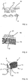
- Fig. 1 shows a perspective view of a double cone synchronizer ring.
- the double-cone synchronizer ring is formed from a first synchronizer ring section 1, which is connected to a second synchronizer ring section 2.
- the first 1 and the second synchronizer ring section 2 are in Fig. 2 shown separately.
- a first ring gear 6 extends from the first outer side 3.
- a second ring gear 8 extends from the second outer side 4 of the second synchronizing ring section 2 in the vicinity of another first end face 7
- the first outer side 3 opposite first inner surface 9 has a tapered conical surface from the first end face 5 toward an oppositely formed second end face 10.
- the second synchronizing ring section 2 has at its second inner surface 12 a further conical surface tapering from the further first end face 7 towards a further second end face 11.
- each of the synchronizer ring sections 1, 2 each have three webs 13 and three recesses 14. But it may also be that each of the synchronizer ring sections 1, 2 each have two, four, five or more webs 13 and corresponding recesses 14.
- the 3 and 4 show perspective views of a synchronizer ring section 1, 2 after the forming.
- the synchronizer ring portion 1, 2 is preferably using the same die by means of forming methods (for example Warm forging or cold forging) made from a semi-finished product.
- the synchronizing ring section 1, 2 already has a conical surface on its inner surface 9, 12 after the forming step, in which the second grooves 16 are formed.
- On the outer side 3, 4 of the ring gear 6, 8 is formed.
- the teeth of the ring gear 6, 8 are connected in the vicinity of the first end face 5, 7 by means of a carrier web 17.
- the reference numeral 18 are precursor ribs and designated by the reference numeral 19 precursor recesses.
- FIGS. 5 and 6 show perspective views of the synchronizer ring section 1, 2 after machining.
- the first end face 5, 7 is turned off until the support web 17 is completely removed and the first end face 5, 7 intersects the teeth of the ring gear 6, 8 (see Fig. 6 ).
- the first grooves 15 are screwed by means of machining in the conical surface.
- the precursor webs 18 and the precursor recesses 19 are machined.
- a groove-like recess 20 is incorporated in the recess 14, preferably on a hump-shaped projection formed therein, which extends in the circumferential direction.
- the sections circumferentially extending webs 13 are provided with a corresponding to the groove-like recess 20 formed connecting rib 21 which projects to an axis A of the synchronizer ring portion 1, 2 and extends in a circumferential direction.
- the thus formed synchronizer ring sections 1, 2 are then pressed with their second end faces 10, 11 against each other so that the webs 13 engage in the corresponding recesses 14 on the opposite other synchronizer ring section 1, 2.
- the connecting ribs 21 engage in each case in the groove-like depressions 20 in the recesses 14 a.
- Fig. 10 shows in detail the connection between the first 1 and the second synchronizer ring section 2. Because of the engagement of the connecting rib 21 in the groove-like recess 20, the synchronizer ring sections 1, 2 are firmly connected together in the axial direction. Because of the formation of the webs 13 and the corresponding configuration of the recesses 14 in the circumferential direction only in the circumferential direction, the synchronizer ring sections 1, 2 are positively connected to each other in the radial direction, so that a relative movement between the synchronizer ring sections 1, 2 in the assembled state is not possible.
Landscapes
- Engineering & Computer Science (AREA)
- General Engineering & Computer Science (AREA)
- Mechanical Engineering (AREA)
- Mechanical Operated Clutches (AREA)
- Forging (AREA)
Description
- Die Erfindung betrifft ein Verfahren zur Herstellung eines Doppelkonus-Synchronrings nach dem Oberbegriff des Anspruchs 1.
- Ein solches Verfahren ist aus der
DE 10 2011 016238 A1 bekannt. Nach dem Stand der Technik sind Synchronringe für Schaltgetriebe, insbesondere für Schaltgetriebe von Kraftfahrzeugen, allgemein bekannt. Es wird beispielhaft auf dieDE 10 2005 007 957 A1 verwiesen. - Üblicherweise weisen Synchronringe an ihrer Innenseite und/oder ihrer Außenseite eine konische Fläche auf. Sofern der Synchronring sowohl an der Innenseite als auch an der gegenüberliegenden Außenseite eine konische Fläche aufweist, verlaufen diese Flächen üblicherweise parallel.
- Die vorliegende Erfindung betrifft dagegen die Herstellung eines Synchronrings, welcher an seiner Innenseite mit zwei konischen Flächen versehen ist. Die beiden konischen Flächen sind so ausgebildet, dass sie sich jeweils von einer Stirnseite in Richtung der gegenüberliegenden anderen Stirnseite hin verjüngen. Infolgedessen ist an der Innenseite etwa mittig eine radial umlaufende Kante gebildet. Im Sinne der vorliegenden Erfindung wird unter einem "Doppelkonus-Synchronring" ein Synchronring verstanden, welcher an seiner Innenseite zwei konische Flächen aufweist, von denen sich jede zu einer der Stirnseiten hin erweitert.
- Aufgabe der Erfindung ist es, ein möglichst einfaches und kostengünstiges Verfahren zur Herstellung eines Doppelkonus-Synchronrings anzugeben.
- Diese Aufgabe wird durch die Merkmale des Patentanspruchs 1 gelöst. Zweckmäßige Ausgestaltungen der Erfindung ergeben sich aus den Merkmalen der Patentansprüche 2 bis 6. Nach Maßgabe der Erfindung wird zur Herstellung eines Doppelkonus-Synchronrings ein Verfahren mit folgenden Schritten vorgeschlagen:
- Herstellen eines ersten Synchronringabschnitts und eines zweiten Synchronringabschnitts derart, dass der erste und der zweite Synchronringabschnitt jeweils an seiner radial umlaufenden Außenfläche in der Nähe einer ersten Stirnseite einen Zahnkranz und jeweils eine von der ersten Stirnseite zu einer gegenüberliegenden zweiten Stirnseite hin sich verjüngende konische Innenfläche aufweist, und
- Fügen des ersten und des zweiten Synchronringabschnitts, so dass deren zweite Stirnseiten aufeinanderliegen.
- Im Sinne der vorliegenden Erfindung wird unter dem Begriff "Stirnseite" eine Seite bzw. Fläche des Synchronringabschnitts verstanden, welche senkrecht zur Achse bzw. Drehachse des Synchronringabschnitts verläuft. Eine erste und eine zweite Stirnseite des Synchronringabschnitts verlaufen im Wesentlichen parallel zueinander.
- Nach dem erfindungsgemäßen Verfahren werden zunächst ein erster und ein zweiter Synchronringabschnitt hergestellt. Die Synchronringabschnitte werden im ersten Verfahrensschritt zumindest abschnittsweise mit einem Übermaß hergestellt. In einem zweiten Verfahrensschritt erfolgt sodann optional ein spanabhebendes Bearbeiten der Synchronringabschnitte. Dabei werden die mit einem Übermaß hergestellten Flächen auf ein vorgegebenes Maß bzw. eine vorgegebene Ausgestaltung gebracht. Vorzugsweise erfolgt das optionale spanabhebende Bearbeiten der Synchronringabschnitte jeweils zumindest im Bereich der ersten Stirnseite, so dass die erste Stirnseite den Zahnkranz schneidet. Schließlich werden die spanabhebend bearbeiteten Synchronringabschnitte in einem dritten Verfahrensschritt miteinander verbunden, so dass sie mit ihren zweiten Stirnseiten aufeinanderliegen.
- Mit dem erfindungsgemäßen Verfahren lässt sich ein Doppelkonus-Synchronring relativ einfach und kostengünstig herstellen. Zur Herstellung der Synchronringabschnitte kann auf Produktionsmittel zurückgegriffen werden, wie sie für die Herstellung herkömmlicher Synchronringe mit einer einzigen Innenkonusfläche verwendet werden.
- Nach einer vorteilhaften Ausgestaltung werden der erste und der zweite Synchronringabschnitt mittels Umformen aus einem Halbzeug hergestellt. Das Umformen wird vorteilhafterweise mittels Gesenkschmieden oder Kaltumformen durchgeführt. Dabei kann das Halbzeug beispielsweise aus Messing, Stahl oder dgl. hergestellt sein. Es ist auch möglich, den ersten und den zweiten Synchronringabschnitt mittels Sintern aus einem Metallpulver herzustellen.
- Nach einer vorteilhaften Ausgestaltung werden der erste und der zweite Synchronringabschnitt in identischer Ausbildung, vorzugsweise unter Verwendung desselben Werkzeugs, hergestellt. Damit können weiter Herstellungskosten eingespart werden.
- Das Halbzeug wird mittels eines Umformverfahrens (beispielsweise Halbwarmumformen oder Kaltmassivumformen) umgeformt. Dabei ist das Halbzeug zweckmäßigerweise aus Messing hergestellt. Auch eine Kaltumformung kommt in Betracht.
- Vorteilhafterweise werden sodann in die konischen Innenflächen der Synchronringabschnitte mittels spanabhebender Bearbeitung radial umlaufende oder gewindeförmige erste Rillen eingearbeitet. Durch die ersten Rillen wird die Ausbildung einer Öl-Gleitschicht zwischen der Konusfläche und einer dazu korrespondierenden weiteren Konusfläche z. B. an einem Losrad vermieden.
- Nach einer weiteren vorteilhaften Ausgestaltung sind in den konischen Innenflächen axial verlaufende zweite Rillen vorgesehen. Auch die zweiten Rillen tragen zur Vermeidung der Ausbildung einer Öl-Gleitschicht bei. Die zweiten Rillen können bereits beim Umformen hergestellt werden.
- Alternativ können die vorstehend im Zusammenhang mit den ersten und zweiten Rillen beschriebenen Funktionen auch durch das Aufbringen von Reibmaterialien auf den Innenflächenbereich realisiert werden.
- Mittels spanabhebender Bearbeitung können auch Bohrungen und/oder Gewindebohrungen hergestellt werden, mit denen unter Verwendung von Schrauben oder Nieten Verbindungen zwischen dem ersten und dem zweiten Synchronringabschnitt hergestellt werden können. Erfindungsgemäß weist der mittels Umformen hergestellte Synchronabschnitt an der zweiten Stirnseite zumindest einen von der zweiten Stirnseite sich in axialer Richtung erstreckenden Verbindungsabschnitt und/oder zumindest eine korrespondierend zum Verbindungsabschnitt ausgebildete Ausnehmung auf. Beim Fügen greift der zumindest eine Verbindungsabschnitt des ersten Synchronringabschnitts in die Ausnehmung am zweiten Synchronringabschnitt ein. Der Verbindungsabschnitt und die Ausnehmung sind zweckmäßigerweise so ausgestaltet, dass durch den Eingriff des Verbindungsabschnitts in die Ausnehmung eine radiale Relativbewegung der miteinander verbundenen ersten und zweiten Synchronringabschnitte verhindert wird. Der Verbindungsabschnitt und die Ausnehmung können ferner so ausgestaltet sein, dass auch eine axiale Relativbewegung der miteinander verbundenen ersten und zweiten Synchronringabschnitte verhindert wird. Erfindungsgemäß ist der Verbindungsabschnitt ein sich von der zweiten Stirnseite in axialer Richtung erstreckender Steg oder Bolzen. Der Steg kann sich über einen Abschnitt des Umfangs erstrecken. Er kann sich auch über den gesamten Umfang des jeweiligen Synchronringabschnitts erstrecken. Es können auch mehrere Stegabschnitte, welche sich vorzugsweise jeweils in Umfangsrichtung erstrecken, vorgesehen sein. Erfindungsgemäß werden an einer der Achse des Synchronringabschnitts zugewandten Steg-Innenseite eine Verbindungsrippe, und in der Ausnehmung eine zur Verbindungsrippe korrespondierende rillenartige Vertiefung jeweils mittels spanabhebender Bearbeitung hergestellt. Das ermöglicht es, den ersten Synchronringabschnitt mit dem zweiten Synchronringabschnitt formschlüssig zu verrasten. Damit kann eine besonders einfache und haltbare Verbindung zwischen dem ersten und dem zweiten Synchronringabschnitt hergestellt werden. Die Verbindung ist dabei so ausgestaltet, dass sowohl eine radiale als auch eine axiale Bewegung der beiden Synchronringabschnitte zueinander verhindert werden.
- Der erste Synchronringabschnitt wird erfindungsgemäß mit dem zweiten Synchronringabschnitt durch Herstellen eines Eingriffs der Verbindungsrippe in die dazu korrespondierende rillenartige Vertiefung gefügt. Ein solches Fügen kann durch einfache Ausübung eines axialen Drucks erreicht werden. Zusätzlich kann es erforderlich sein, die Verbindungsrippe in radialer Richtung zu pressen.
- Nachfolgend wird ein Ausführungsbeispiel der Erfindung anhand der Zeichnungen näher erläutert. Es zeigen:
- Fig. 1
- eine perspektivische Ansicht eines Doppelkonus-Synchronrings,
- Fig. 2
- eine perspektivische Ansicht eines ersten und eines zweiten Synchronringabschnitts gemäß
Fig. 1 , - Fig. 3
- eine perspektivische Ansicht eines Synchronringabschnitts nach dem Umformen,
- Fig. 4
- eine weitere perspektivische Ansicht gemäß
Fig. 3 , - Fig. 5
- eine perspektivische Ansicht eines Synchronringabschnitts nach der spanabhebenden Bearbeitung,
- Fig. 6
- eine weitere perspektivische Ansicht gemäß
Fig. 5 , - Fig. 7
- eine perspektivische Ansicht des ersten und des zweiten Synchronringabschnitts beim Fügen,
- Fig. 8
- eine Detailansicht gemäß
Fig. 2 , - Fig. 9
- eine weitere Detailansicht gemäß
Fig. 2 und - Fig. 10
- eine perspektivische Teilschnittansicht gemäß der Schnittlinie A-A' in
Fig. 1 . -
Fig. 1 zeigt eine perspektivische Ansicht eines Doppelkonus-Synchronrings. Der Doppelkonus-Synchronring ist gebildet aus einem ersten Synchronringabschnitt 1, welcher mit einem zweiten Synchronringabschnitt 2 verbunden ist. Der erste 1 und der zweite Synchronringabschnitt 2 sind inFig. 2 separat dargestellt. Die, hier vorteilhafterweise identisch ausgeführten, ersten 1 und zweiten Synchronringabschnitte 2 weisen jeweils eine radial umlaufende erste 3 sowie zweite Außenseite 4 auf. In der Nähe einer am ersten Synchronringabschnitt 1 vorgesehenen ersten Stirnseite 5 erstreckt sich von der ersten Außenseite 3 ein erster Zahnkranz 6. Analog erstreckt sich von der zweiten Außenseite 4 des zweiten Synchronringabschnitts 2 in der Nähe einer weiteren ersten Stirnseite 7 ein zweiter Zahnkranz 8. Eine der ersten Außenseite 3 gegenüberliegende erste Innenfläche 9 weist eine von der ersten Stirnseite 5 hin zu einer gegenüberliegend ausgebildeten zweiten Stirnseite 10 sich verjüngende konische Fläche auf. Analog weist der zweite Synchronringabschnitt 2 an seiner zweiten Innenfläche 12 eine von der weiteren ersten Stirnseite 7 sich hin zu einer weiteren zweiten Stirnseite 11 sich verjüngende weitere konische Fläche auf. - Von der zweiten Stirnseite 10 sowie der weiteren zweiten Stirnseite 11 erstrecken sich jeweils Stege 13. Ferner weisen die zweite Stirnseite 10 sowie die weitere zweite Stirnseite 11 Ausnehmungen 14 auf, welche korrespondierend zu den Stegen 13 ausgebildet sind. Im vorliegenden Ausführungsbeispiel weist jeder der Synchronringabschnitte 1, 2 jeweils drei Stege 13 sowie drei Ausnehmungen 14 auf. Es kann aber auch sein, dass jeder der Synchronringabschnitte 1, 2 jeweils zwei, vier, fünf oder mehr Stege 13 und dazu korrespondierende Ausnehmungen 14 aufweist.
- Wie aus den
Fig. 1 und 2 ersichtlich ist, weisen die Innenflächen 9, 12 radial umlaufende erste Rillen 15 sowie axial verlaufende zweite Rillen 16 auf. - Die Herstellung des in den
Fig. 1 und 2 gezeigten Doppelkonus-Synchronrings wird in denFig. 3 bis 10 näher erläutert. - Die
Fig. 3 und 4 zeigen perspektivische Ansichten eines Synchronringabschnitts 1, 2 nach dem Umformen. Der Synchronringabschnitt 1, 2 wird vorzugsweise unter Verwendung desselben Gesenks mittels Umformverfahren (beispielsweise Halbwarmumformen oder Kaltmassivumformen) aus einem Halbzeug hergestellt. Der Synchronringabschnitt 1, 2 weist nach dem Umformschritt an seiner Innenfläche 9, 12 bereits eine konische Fläche auf, in welche die zweiten Rillen 16 eingeformt sind. An der Außenseite 3, 4 ist der Zahnkranz 6, 8 angeformt. Die Zähne des Zahnkranzes 6, 8 sind in der Nähe der ersten Stirnseite 5, 7 mittels eines Trägerstegs 17 verbunden. Mit dem Bezugszeichen 18 sind Vorläufer-Stege und mit dem Bezugszeichen 19 Vorläufer-Ausnehmungen bezeichnet. - Die
Fig. 5 und 6 zeigen perspektivische Ansichten des Synchronringabschnitts 1, 2 nach der spanabhebenden Bearbeitung. Bei der spanabhebenden Bearbeitung wird insbesondere die erste Stirnseite 5, 7 abgedreht, bis der Trägersteg 17 vollständig entfernt ist und die erste Stirnseite 5, 7 die Zähne des Zahnkranzes 6, 8 schneidet (sieheFig. 6 ). Ferner werden die ersten Rillen 15 mittels spanabhebender Bearbeitung in die konische Fläche eingedreht. Schließlich werden die Vorläufer-Stege 18 und die Vorläufer-Ausnehmungen 19 spanabhebend bearbeitet. Wie insbesondere ausFig. 8 ersichtlich ist, wird in die Ausnehmung 14, vorzugsweise an einem darin gebildeten höckerartigen Vorsprung, eine rillenartige Vertiefung 20 eingearbeitet, welche sich in umlaufender Richtung erstreckt. Die abschnittsweise umlaufend sich erstreckenden Stege 13 werden mit einer korrespondierend zur rillenartigen Vertiefung 20 ausgebildeten Verbindungsrippe 21 versehen, welche zu einer Achse A des Synchronringabschnitts 1, 2 vorspringt und sich in umlaufender Richtung erstreckt. - Die so ausgebildeten Synchronringabschnitte 1, 2 werden sodann mit ihren zweiten Stirnseiten 10, 11 so gegeneinander gepresst, dass die Stege 13 in die dazu korrespondierenden Ausnehmungen 14 am gegenüberliegenden anderen Synchronringabschnitt 1, 2 eingreifen. Dabei rasten die Verbindungsrippen 21 jeweils in die rillenartigen Vertiefungen 20 in den Ausnehmungen 14 ein.
-
Fig. 10 zeigt im Detail die Verbindung zwischen dem ersten 1 und dem zweiten Synchronringabschnitt 2. Wegen des Eingriffs der Verbindungsrippe 21 in die rillenartige Vertiefung 20 werden die Synchronringabschnitte 1, 2 in axialer Richtung fest miteinander verbunden. Wegen der in Umfangsrichtung lediglich abschnittsweisen Ausbildung der Stege 13 und der dazu korrespondierenden Ausbildung der Ausnehmungen 14 werden die Synchronringabschnitte 1, 2 auch in radialer Richtung formschlüssig miteinander verbunden, so dass eine Relativbewegung zwischen den Synchronringabschnitten 1, 2 im gefügten Zustand nicht möglich ist. -
- 1
- erster Synchronringabschnitt
- 2
- zweiter Synchronringabschnitt
- 3
- erste Außenseite
- 4
- zweite Außenseite
- 5
- erste Stirnseite
- 6
- erster Zahnkranz
- 7
- weitere erste Stirnseite
- 8
- zweiter Zahnkranz
- 9
- erste Innenfläche
- 10
- zweite Stirnseite
- 11
- weitere zweite Stirnseite
- 12
- zweite Innenfläche
- 13
- Steg
- 14
- Ausnehmung
- 15
- erste Rille
- 16
- zweite Rille
- 17
- Trägersteg
- 18
- Vorläufer-Steg
- 19
- Vorläufer-Ausnehmung
- 20
- rillenartige Vertiefung
- 21
- Verbindungsrippe
- A
- Achse
Claims (6)
- Verfahren zur Herstellung eines Doppelkonus-Synchronrings mit folgenden Schritten:Herstellen eines ersten Synchronringabschnitts (1) und eines zweiten Synchronringabschnitts (2) derart,dass der erste (1) und der zweite Synchronringabschnitt (2) jeweils an seiner radial umlaufenden Außenfläche (3, 4) in der Nähe einer ersten Stirnseite (5, 7) einen Zahnkranz (6, 8) und jeweils eine von der ersten Stirnseite (5, 7) zu einer gegenüberliegenden zweiten Stirnseite (10, 11) hin sich verjüngende konische Innenfläche (9, 12) aufweist, undFügen des ersten (1) und des zweiten Synchronringabschnitts (2),so dass deren zweite Stirnseiten (10, 11) aufeinanderliegen, dadurch gekennzeichnet, dass der mittels Umformen hergestellte Synchronringabschnitt (1, 2) an der zweiten Stirnseite (10, 11) zumindest einen von der zweiten Stirnseite (10, 11) sich in axialer Richtung erstreckenden Verbindungsabschnitt (13) und/oder zumindest eine korrespondierend zum Verbindungsabschnitt (13) ausgebildete Ausnehmung (14) aufweist, und beim Fügen der zumindest eine Verbindungsabschnitt (13) des ersten Synchronringabschnitts (1) in die Ausnehmung (14) am zweiten Synchronringabschnitt (2) eingreift,wobei der Verbindungsabschnitt (13) ein sich von der zweiten Stirnseite (10, 11) in axialer Richtung erstreckender Steg (13) oder Bolzen ist,wobei an einer der Achse (A) des Synchronringabschnitts (1, 2) zugewandten Steg-Innenseite eine Verbindungsrippe (21), und in der Ausnehmung (14) eine zur Verbindungsrippe (21) korrespondierende rillenartige Vertiefung (20) jeweils mittels spanabhebender Bearbeitung hergestellt werden, und wobei der erste Synchronringabschnitt (1) mit dem zweiten Synchronringabschnitt (2) durch Herstellen eines Eingriffs der Verbindungsrippe (21) in die dazu korrespondierende rillenartige Vertiefung (20) gefügt wird.
- Verfahren nach Anspruch 1,
ferner umfassend den Schritt des spanabhebenden Bearbeitens der Synchronringabschnitte (1, 2) jeweils zumindest im Bereich der ersten Stirnseite (5, 7), so dass die erste Stirnseite (5, 7) den Zahnkranz (6, 8) schneidet. - Verfahren nach Anspruch 1 oder 2,
wobei das Umformen mittels Gesenkschmieden oder Kaltumformen durchgeführt wird. - Verfahren nach einem der vorhergehenden Ansprüche,
wobei der erste (1) und der zweite Synchronringabschnitt (2) in identischer Ausbildung, vorzugsweise unter Verwendung desselben Werkzeugs, hergestellt werden. - Verfahren nach einem der vorhergehenden Ansprüche,
wobei in die konischen Innenflächen (9, 12) mittels spanabhebender Bearbeitung radial umlaufende oder gewindeförmige erste Rillen (15) eingearbeitet werden. - Verfahren nach einen der Ansprüche 1 bis 5,
wobei auf den konischen Innenflächen (9, 12) Reibmaterialien aufgebracht werden.
Applications Claiming Priority (1)
| Application Number | Priority Date | Filing Date | Title |
|---|---|---|---|
| DE102015015411.7A DE102015015411B4 (de) | 2015-11-27 | 2015-11-27 | Verfahren zur Herstellung eines Doppelkonus-Synchronrings |
Publications (2)
| Publication Number | Publication Date |
|---|---|
| EP3173184A1 EP3173184A1 (de) | 2017-05-31 |
| EP3173184B1 true EP3173184B1 (de) | 2018-08-01 |
Family
ID=57389153
Family Applications (1)
| Application Number | Title | Priority Date | Filing Date |
|---|---|---|---|
| EP16002460.0A Not-in-force EP3173184B1 (de) | 2015-11-27 | 2016-11-18 | Verfahren zur herstellung eines doppelkonus-synchronrings |
Country Status (6)
| Country | Link |
|---|---|
| EP (1) | EP3173184B1 (de) |
| JP (1) | JP6783123B2 (de) |
| KR (1) | KR20170062397A (de) |
| CN (1) | CN106812826B (de) |
| BR (1) | BR102016027100A2 (de) |
| DE (1) | DE102015015411B4 (de) |
Families Citing this family (1)
| Publication number | Priority date | Publication date | Assignee | Title |
|---|---|---|---|---|
| CN108032035B (zh) * | 2017-11-27 | 2021-11-12 | 佛山市荣鑫宝数控设备有限公司 | 一种包带环的加工方法 |
Family Cites Families (18)
| Publication number | Priority date | Publication date | Assignee | Title |
|---|---|---|---|---|
| JPH0685972B2 (ja) * | 1984-10-12 | 1994-11-02 | 富士重工業株式会社 | スプラインピ−スの冷間塑性加工方法 |
| JPS62227544A (ja) * | 1986-03-31 | 1987-10-06 | Mitsubishi Metal Corp | 鉄基ブロツクリングの製造方法 |
| JPH0241723U (de) * | 1988-09-14 | 1990-03-22 | ||
| JPH0558966U (ja) * | 1992-01-24 | 1993-08-03 | 三菱自動車工業株式会社 | シンクロナイザ |
| DE4324814A1 (de) * | 1993-07-23 | 1995-01-26 | Zahnradfabrik Friedrichshafen | Getriebeschaltung mit Sperrsynchronisierung |
| DE19537209A1 (de) * | 1995-10-06 | 1997-04-10 | Schaeffler Waelzlager Kg | Verfahren zum Herstellen von Synchronringen |
| FR2751712B1 (fr) * | 1996-07-24 | 1998-10-30 | Valeo | Bague de synchronisation pour un synchroniseur de boite de vitesses |
| DE10021710A1 (de) * | 2000-05-04 | 2001-11-08 | Schaeffler Waelzlager Ohg | Verfahren zum Herstellen eines Synchronringes |
| JP4257562B2 (ja) * | 2000-06-12 | 2009-04-22 | 三菱マテリアル株式会社 | チャンファー部がすぐれた疲労強度を有する銅合金製熱間型鍛造シンクロナイザーリングの製造方法 |
| DE102004060016A1 (de) * | 2004-12-14 | 2006-06-22 | Schaeffler Kg | Reibpaarung mit wenigstens einem ersten Reibkörper als Gegenkörper |
| DE102005007957A1 (de) | 2005-02-22 | 2006-08-31 | Zf Friedrichshafen Ag | Synchronisiereinrichtung für ein Schaltgetriebe, insbesondere eines Kraftfahrzeuges |
| DE102009007849B4 (de) * | 2009-02-06 | 2016-03-31 | Audi Ag | Synchronring für eine Außenkonussynchronisierung |
| US8863928B2 (en) * | 2009-09-14 | 2014-10-21 | Hoerbiger Antriebstechnik Holding Gmbh | Assembly comprising two synchroniser rings |
| CN201795026U (zh) * | 2010-01-08 | 2011-04-13 | 程甫煜 | 双锥面锁销式惯性同步器 |
| DE102010036280B4 (de) * | 2010-09-03 | 2013-05-02 | Hoerbiger Antriebstechnik Holding Gmbh | Transmitter für eine Synchronisierungsbaugruppe eines Schaltgetriebes |
| DE102011016238A1 (de) * | 2011-04-06 | 2012-10-11 | Daimler Ag | Kraftfahrzeuggetriebeschaltvorrichtung mit zumindest einer Synchroneinheit |
| DE102011111216A1 (de) * | 2011-08-20 | 2013-02-21 | Sona Blw Präzisionsschmiede Gmbh | Synchronring |
| DE102012209208A1 (de) * | 2012-05-31 | 2013-12-05 | Schaeffler Technologies AG & Co. KG | Synchronisiereinrichtung |
-
2015
- 2015-11-27 DE DE102015015411.7A patent/DE102015015411B4/de not_active Expired - Fee Related
-
2016
- 2016-11-18 EP EP16002460.0A patent/EP3173184B1/de not_active Not-in-force
- 2016-11-18 BR BR102016027100A patent/BR102016027100A2/pt active Search and Examination
- 2016-11-24 KR KR1020160157313A patent/KR20170062397A/ko not_active Withdrawn
- 2016-11-25 JP JP2016229077A patent/JP6783123B2/ja not_active Expired - Fee Related
- 2016-11-25 CN CN201611060131.4A patent/CN106812826B/zh not_active Expired - Fee Related
Also Published As
| Publication number | Publication date |
|---|---|
| DE102015015411B4 (de) | 2018-05-24 |
| EP3173184A1 (de) | 2017-05-31 |
| DE102015015411A1 (de) | 2017-06-01 |
| BR102016027100A2 (pt) | 2017-06-06 |
| JP2017141953A (ja) | 2017-08-17 |
| CN106812826B (zh) | 2020-04-17 |
| KR20170062397A (ko) | 2017-06-07 |
| JP6783123B2 (ja) | 2020-11-11 |
| CN106812826A (zh) | 2017-06-09 |
Similar Documents
| Publication | Publication Date | Title |
|---|---|---|
| EP2100049B1 (de) | Kupplungskörper mit angeformtem konus | |
| EP3212433B1 (de) | Fahrzeugrad mit einer verbindung zwischen einer radfelge und einer radscheibe und verfahren zu dessen herstellung | |
| EP2233759B1 (de) | Gebaute Bundlagerschale mit halbschalenförmigem Radiallagerteil und mit wenigstens einem scheibenförmigen Axiallagerteil | |
| EP2869947B1 (de) | Verfahren zur herstellung eines verbindungselements zur übertragung von drehbewegungen sowie dadurch hergestelltes verbindungselement | |
| EP2184525A1 (de) | Rohrverbindung mit einem Rohr und Verfahren zur Herstellung eines Verbindungsabschnitts einer Rohrverbindung | |
| DE4211186A1 (de) | Verfahren insbesondere zur pulvermetallurgischen Herstellung eines Zahnrades mit einem Kupplungskörper | |
| DE102009048377B4 (de) | Verfahren zum Herstellen von Lamellen einer Reibkupplung | |
| WO2006097194A1 (de) | Verfahren zur herstellung einer gelenkanbindung und gelenkanbindung | |
| EP3341617B1 (de) | Bohrschraube | |
| EP0085388B1 (de) | Verfahren zur Herstellung einer Metallmuffe aus einem zylindrischen Rohrabschnitt | |
| DE102007023972A1 (de) | Verfahren zur Herstellung einer Nabe im Drückverfahren mittels wenigstens einer drehbaren Drückrolle | |
| DE102012202446A1 (de) | Getrieberad, insbesondere Sonnenrad für ein Differenzialgetriebe | |
| DE102017115712B4 (de) | Verbundbremsscheibe | |
| DE102006012031A1 (de) | Verfahren zur Herstellung einer Gelenkanbindung und Gelenkanbindung | |
| DE102015015411B4 (de) | Verfahren zur Herstellung eines Doppelkonus-Synchronrings | |
| DE102015219855A1 (de) | Hohlrad mit Innenverzahnung und Kronenverzahnung, sowie Verfahren zu dessen Herstellung und Schaltgetriebe mit solchem Hohlrad | |
| DE102013215617C5 (de) | Kupplungskörper einer Synchronisiervorrichtung | |
| DE102012011020A1 (de) | Stanzniet, Nietverbindung und Nietverfahren | |
| WO2011160241A1 (de) | Verfahren zur herstellung einer innenrändelung in einer aufnahmebohrung eines nabenkörpers | |
| DE102019206520A1 (de) | Welle-Nabe-Verbindung sowie Verfahren zur Herstellung einer solchen Welle-Nabe-Verbindung | |
| EP4619655A1 (de) | Bremsscheibe | |
| DE102012202455A1 (de) | Differenzialbaugruppe mit einer Kunststoffverbindungsmethode und Montage eines Planetenträgers | |
| WO2015054708A1 (de) | Bearbeitungswerkzeug und verfahren zur herstellung eines bearbeitungswerkzeugs | |
| DE102014208806A1 (de) | Vorrichtung zur Betätigung eines formschlüssigen Schaltelements | |
| WO2018019939A1 (de) | Gebaute halbschalenförmige bundlagerschale |
Legal Events
| Date | Code | Title | Description |
|---|---|---|---|
| PUAI | Public reference made under article 153(3) epc to a published international application that has entered the european phase |
Free format text: ORIGINAL CODE: 0009012 |
|
| AK | Designated contracting states |
Kind code of ref document: A1 Designated state(s): AL AT BE BG CH CY CZ DE DK EE ES FI FR GB GR HR HU IE IS IT LI LT LU LV MC MK MT NL NO PL PT RO RS SE SI SK SM TR |
|
| AX | Request for extension of the european patent |
Extension state: BA ME |
|
| 17P | Request for examination filed |
Effective date: 20171129 |
|
| RBV | Designated contracting states (corrected) |
Designated state(s): AL AT BE BG CH CY CZ DE DK EE ES FI FR GB GR HR HU IE IS IT LI LT LU LV MC MK MT NL NO PL PT RO RS SE SI SK SM TR |
|
| GRAP | Despatch of communication of intention to grant a patent |
Free format text: ORIGINAL CODE: EPIDOSNIGR1 |
|
| RIC1 | Information provided on ipc code assigned before grant |
Ipc: B23P 15/00 20060101AFI20180301BHEP Ipc: F16D 23/02 20060101ALI20180301BHEP Ipc: F16D 23/06 20060101ALI20180301BHEP |
|
| INTG | Intention to grant announced |
Effective date: 20180323 |
|
| GRAS | Grant fee paid |
Free format text: ORIGINAL CODE: EPIDOSNIGR3 |
|
| GRAA | (expected) grant |
Free format text: ORIGINAL CODE: 0009210 |
|
| AK | Designated contracting states |
Kind code of ref document: B1 Designated state(s): AL AT BE BG CH CY CZ DE DK EE ES FI FR GB GR HR HU IE IS IT LI LT LU LV MC MK MT NL NO PL PT RO RS SE SI SK SM TR |
|
| REG | Reference to a national code |
Ref country code: GB Ref legal event code: FG4D Free format text: NOT ENGLISH |
|
| REG | Reference to a national code |
Ref country code: CH Ref legal event code: EP Ref country code: AT Ref legal event code: REF Ref document number: 1023734 Country of ref document: AT Kind code of ref document: T Effective date: 20180815 |
|
| REG | Reference to a national code |
Ref country code: IE Ref legal event code: FG4D Free format text: LANGUAGE OF EP DOCUMENT: GERMAN |
|
| REG | Reference to a national code |
Ref country code: DE Ref legal event code: R096 Ref document number: 502016001532 Country of ref document: DE |
|
| REG | Reference to a national code |
Ref country code: NL Ref legal event code: MP Effective date: 20180801 |
|
| REG | Reference to a national code |
Ref country code: LT Ref legal event code: MG4D |
|
| REG | Reference to a national code |
Ref country code: SK Ref legal event code: T3 Ref document number: E 28485 Country of ref document: SK |
|
| PG25 | Lapsed in a contracting state [announced via postgrant information from national office to epo] |
Ref country code: RS Free format text: LAPSE BECAUSE OF FAILURE TO SUBMIT A TRANSLATION OF THE DESCRIPTION OR TO PAY THE FEE WITHIN THE PRESCRIBED TIME-LIMIT Effective date: 20180801 Ref country code: LT Free format text: LAPSE BECAUSE OF FAILURE TO SUBMIT A TRANSLATION OF THE DESCRIPTION OR TO PAY THE FEE WITHIN THE PRESCRIBED TIME-LIMIT Effective date: 20180801 Ref country code: SE Free format text: LAPSE BECAUSE OF FAILURE TO SUBMIT A TRANSLATION OF THE DESCRIPTION OR TO PAY THE FEE WITHIN THE PRESCRIBED TIME-LIMIT Effective date: 20180801 Ref country code: BG Free format text: LAPSE BECAUSE OF FAILURE TO SUBMIT A TRANSLATION OF THE DESCRIPTION OR TO PAY THE FEE WITHIN THE PRESCRIBED TIME-LIMIT Effective date: 20181101 Ref country code: NL Free format text: LAPSE BECAUSE OF FAILURE TO SUBMIT A TRANSLATION OF THE DESCRIPTION OR TO PAY THE FEE WITHIN THE PRESCRIBED TIME-LIMIT Effective date: 20180801 Ref country code: PL Free format text: LAPSE BECAUSE OF FAILURE TO SUBMIT A TRANSLATION OF THE DESCRIPTION OR TO PAY THE FEE WITHIN THE PRESCRIBED TIME-LIMIT Effective date: 20180801 Ref country code: FI Free format text: LAPSE BECAUSE OF FAILURE TO SUBMIT A TRANSLATION OF THE DESCRIPTION OR TO PAY THE FEE WITHIN THE PRESCRIBED TIME-LIMIT Effective date: 20180801 Ref country code: GR Free format text: LAPSE BECAUSE OF FAILURE TO SUBMIT A TRANSLATION OF THE DESCRIPTION OR TO PAY THE FEE WITHIN THE PRESCRIBED TIME-LIMIT Effective date: 20181102 Ref country code: NO Free format text: LAPSE BECAUSE OF FAILURE TO SUBMIT A TRANSLATION OF THE DESCRIPTION OR TO PAY THE FEE WITHIN THE PRESCRIBED TIME-LIMIT Effective date: 20181101 Ref country code: IS Free format text: LAPSE BECAUSE OF FAILURE TO SUBMIT A TRANSLATION OF THE DESCRIPTION OR TO PAY THE FEE WITHIN THE PRESCRIBED TIME-LIMIT Effective date: 20181201 |
|
| PG25 | Lapsed in a contracting state [announced via postgrant information from national office to epo] |
Ref country code: LV Free format text: LAPSE BECAUSE OF FAILURE TO SUBMIT A TRANSLATION OF THE DESCRIPTION OR TO PAY THE FEE WITHIN THE PRESCRIBED TIME-LIMIT Effective date: 20180801 Ref country code: HR Free format text: LAPSE BECAUSE OF FAILURE TO SUBMIT A TRANSLATION OF THE DESCRIPTION OR TO PAY THE FEE WITHIN THE PRESCRIBED TIME-LIMIT Effective date: 20180801 Ref country code: AL Free format text: LAPSE BECAUSE OF FAILURE TO SUBMIT A TRANSLATION OF THE DESCRIPTION OR TO PAY THE FEE WITHIN THE PRESCRIBED TIME-LIMIT Effective date: 20180801 |
|
| PG25 | Lapsed in a contracting state [announced via postgrant information from national office to epo] |
Ref country code: RO Free format text: LAPSE BECAUSE OF FAILURE TO SUBMIT A TRANSLATION OF THE DESCRIPTION OR TO PAY THE FEE WITHIN THE PRESCRIBED TIME-LIMIT Effective date: 20180801 Ref country code: EE Free format text: LAPSE BECAUSE OF FAILURE TO SUBMIT A TRANSLATION OF THE DESCRIPTION OR TO PAY THE FEE WITHIN THE PRESCRIBED TIME-LIMIT Effective date: 20180801 Ref country code: ES Free format text: LAPSE BECAUSE OF FAILURE TO SUBMIT A TRANSLATION OF THE DESCRIPTION OR TO PAY THE FEE WITHIN THE PRESCRIBED TIME-LIMIT Effective date: 20180801 |
|
| REG | Reference to a national code |
Ref country code: DE Ref legal event code: R097 Ref document number: 502016001532 Country of ref document: DE |
|
| PG25 | Lapsed in a contracting state [announced via postgrant information from national office to epo] |
Ref country code: SM Free format text: LAPSE BECAUSE OF FAILURE TO SUBMIT A TRANSLATION OF THE DESCRIPTION OR TO PAY THE FEE WITHIN THE PRESCRIBED TIME-LIMIT Effective date: 20180801 Ref country code: DK Free format text: LAPSE BECAUSE OF FAILURE TO SUBMIT A TRANSLATION OF THE DESCRIPTION OR TO PAY THE FEE WITHIN THE PRESCRIBED TIME-LIMIT Effective date: 20180801 |
|
| PLBE | No opposition filed within time limit |
Free format text: ORIGINAL CODE: 0009261 |
|
| STAA | Information on the status of an ep patent application or granted ep patent |
Free format text: STATUS: NO OPPOSITION FILED WITHIN TIME LIMIT |
|
| 26N | No opposition filed |
Effective date: 20190503 |
|
| PG25 | Lapsed in a contracting state [announced via postgrant information from national office to epo] |
Ref country code: MC Free format text: LAPSE BECAUSE OF FAILURE TO SUBMIT A TRANSLATION OF THE DESCRIPTION OR TO PAY THE FEE WITHIN THE PRESCRIBED TIME-LIMIT Effective date: 20180801 Ref country code: LU Free format text: LAPSE BECAUSE OF NON-PAYMENT OF DUE FEES Effective date: 20181118 |
|
| REG | Reference to a national code |
Ref country code: BE Ref legal event code: MM Effective date: 20181130 |
|
| REG | Reference to a national code |
Ref country code: IE Ref legal event code: MM4A |
|
| PG25 | Lapsed in a contracting state [announced via postgrant information from national office to epo] |
Ref country code: SI Free format text: LAPSE BECAUSE OF FAILURE TO SUBMIT A TRANSLATION OF THE DESCRIPTION OR TO PAY THE FEE WITHIN THE PRESCRIBED TIME-LIMIT Effective date: 20180801 |
|
| PG25 | Lapsed in a contracting state [announced via postgrant information from national office to epo] |
Ref country code: IE Free format text: LAPSE BECAUSE OF NON-PAYMENT OF DUE FEES Effective date: 20181118 |
|
| PG25 | Lapsed in a contracting state [announced via postgrant information from national office to epo] |
Ref country code: BE Free format text: LAPSE BECAUSE OF NON-PAYMENT OF DUE FEES Effective date: 20181130 |
|
| PG25 | Lapsed in a contracting state [announced via postgrant information from national office to epo] |
Ref country code: MT Free format text: LAPSE BECAUSE OF FAILURE TO SUBMIT A TRANSLATION OF THE DESCRIPTION OR TO PAY THE FEE WITHIN THE PRESCRIBED TIME-LIMIT Effective date: 20180801 |
|
| PG25 | Lapsed in a contracting state [announced via postgrant information from national office to epo] |
Ref country code: TR Free format text: LAPSE BECAUSE OF FAILURE TO SUBMIT A TRANSLATION OF THE DESCRIPTION OR TO PAY THE FEE WITHIN THE PRESCRIBED TIME-LIMIT Effective date: 20180801 |
|
| PG25 | Lapsed in a contracting state [announced via postgrant information from national office to epo] |
Ref country code: PT Free format text: LAPSE BECAUSE OF FAILURE TO SUBMIT A TRANSLATION OF THE DESCRIPTION OR TO PAY THE FEE WITHIN THE PRESCRIBED TIME-LIMIT Effective date: 20180801 |
|
| PG25 | Lapsed in a contracting state [announced via postgrant information from national office to epo] |
Ref country code: MK Free format text: LAPSE BECAUSE OF NON-PAYMENT OF DUE FEES Effective date: 20180801 Ref country code: HU Free format text: LAPSE BECAUSE OF FAILURE TO SUBMIT A TRANSLATION OF THE DESCRIPTION OR TO PAY THE FEE WITHIN THE PRESCRIBED TIME-LIMIT; INVALID AB INITIO Effective date: 20161118 Ref country code: CY Free format text: LAPSE BECAUSE OF FAILURE TO SUBMIT A TRANSLATION OF THE DESCRIPTION OR TO PAY THE FEE WITHIN THE PRESCRIBED TIME-LIMIT Effective date: 20180801 |
|
| REG | Reference to a national code |
Ref country code: CH Ref legal event code: PL |
|
| PG25 | Lapsed in a contracting state [announced via postgrant information from national office to epo] |
Ref country code: LI Free format text: LAPSE BECAUSE OF NON-PAYMENT OF DUE FEES Effective date: 20191130 Ref country code: CH Free format text: LAPSE BECAUSE OF NON-PAYMENT OF DUE FEES Effective date: 20191130 |
|
| PGFP | Annual fee paid to national office [announced via postgrant information from national office to epo] |
Ref country code: CZ Payment date: 20211118 Year of fee payment: 6 Ref country code: GB Payment date: 20211119 Year of fee payment: 6 Ref country code: FR Payment date: 20211122 Year of fee payment: 6 Ref country code: SK Payment date: 20211118 Year of fee payment: 6 |
|
| PGFP | Annual fee paid to national office [announced via postgrant information from national office to epo] |
Ref country code: IT Payment date: 20211119 Year of fee payment: 6 |
|
| PGFP | Annual fee paid to national office [announced via postgrant information from national office to epo] |
Ref country code: DE Payment date: 20220119 Year of fee payment: 6 |
|
| REG | Reference to a national code |
Ref country code: AT Ref legal event code: MM01 Ref document number: 1023734 Country of ref document: AT Kind code of ref document: T Effective date: 20211118 |
|
| PG25 | Lapsed in a contracting state [announced via postgrant information from national office to epo] |
Ref country code: AT Free format text: LAPSE BECAUSE OF NON-PAYMENT OF DUE FEES Effective date: 20211118 |
|
| REG | Reference to a national code |
Ref country code: DE Ref legal event code: R119 Ref document number: 502016001532 Country of ref document: DE |
|
| REG | Reference to a national code |
Ref country code: SK Ref legal event code: MM4A Ref document number: E 28485 Country of ref document: SK Effective date: 20221118 |
|
| GBPC | Gb: european patent ceased through non-payment of renewal fee |
Effective date: 20221118 |
|
| PG25 | Lapsed in a contracting state [announced via postgrant information from national office to epo] |
Ref country code: CZ Free format text: LAPSE BECAUSE OF NON-PAYMENT OF DUE FEES Effective date: 20221118 |
|
| PG25 | Lapsed in a contracting state [announced via postgrant information from national office to epo] |
Ref country code: SK Free format text: LAPSE BECAUSE OF NON-PAYMENT OF DUE FEES Effective date: 20221118 |
|
| PG25 | Lapsed in a contracting state [announced via postgrant information from national office to epo] |
Ref country code: IT Free format text: LAPSE BECAUSE OF NON-PAYMENT OF DUE FEES Effective date: 20221118 Ref country code: GB Free format text: LAPSE BECAUSE OF NON-PAYMENT OF DUE FEES Effective date: 20221118 Ref country code: DE Free format text: LAPSE BECAUSE OF NON-PAYMENT OF DUE FEES Effective date: 20230601 |
|
| PG25 | Lapsed in a contracting state [announced via postgrant information from national office to epo] |
Ref country code: FR Free format text: LAPSE BECAUSE OF NON-PAYMENT OF DUE FEES Effective date: 20221130 |