EP3172425B1 - Module d'aspiration pourvu d'une recirculation de gaz d'échappement intégrée pour moteur à combustion interne - Google Patents
Module d'aspiration pourvu d'une recirculation de gaz d'échappement intégrée pour moteur à combustion interne Download PDFInfo
- Publication number
- EP3172425B1 EP3172425B1 EP15723982.3A EP15723982A EP3172425B1 EP 3172425 B1 EP3172425 B1 EP 3172425B1 EP 15723982 A EP15723982 A EP 15723982A EP 3172425 B1 EP3172425 B1 EP 3172425B1
- Authority
- EP
- European Patent Office
- Prior art keywords
- exhaust gas
- distribution line
- gas distribution
- intake module
- intercooler
- Prior art date
- Legal status (The legal status is an assumption and is not a legal conclusion. Google has not performed a legal analysis and makes no representation as to the accuracy of the status listed.)
- Not-in-force
Links
- 238000002485 combustion reaction Methods 0.000 title claims description 29
- 238000009826 distribution Methods 0.000 claims description 116
- 239000012530 fluid Substances 0.000 claims description 54
- 239000002826 coolant Substances 0.000 claims description 23
- 239000007789 gas Substances 0.000 description 284
- 238000002156 mixing Methods 0.000 description 89
- 238000011109 contamination Methods 0.000 description 3
- 238000004519 manufacturing process Methods 0.000 description 3
- 239000000203 mixture Substances 0.000 description 3
- 238000009827 uniform distribution Methods 0.000 description 3
- 230000001154 acute effect Effects 0.000 description 2
- 230000015572 biosynthetic process Effects 0.000 description 2
- 230000001419 dependent effect Effects 0.000 description 2
- 238000000034 method Methods 0.000 description 2
- 230000002093 peripheral effect Effects 0.000 description 2
- 230000003134 recirculating effect Effects 0.000 description 2
- 238000009825 accumulation Methods 0.000 description 1
- 238000004364 calculation method Methods 0.000 description 1
- 230000005465 channeling Effects 0.000 description 1
- 238000001816 cooling Methods 0.000 description 1
- 238000007599 discharging Methods 0.000 description 1
- 239000003344 environmental pollutant Substances 0.000 description 1
- 230000003116 impacting effect Effects 0.000 description 1
- 230000003993 interaction Effects 0.000 description 1
- 238000002955 isolation Methods 0.000 description 1
- 239000002184 metal Substances 0.000 description 1
- 230000000149 penetrating effect Effects 0.000 description 1
- 231100000719 pollutant Toxicity 0.000 description 1
- 230000002250 progressing effect Effects 0.000 description 1
- 238000004088 simulation Methods 0.000 description 1
- 230000001550 time effect Effects 0.000 description 1
Images


Classifications
-
- F—MECHANICAL ENGINEERING; LIGHTING; HEATING; WEAPONS; BLASTING
- F02—COMBUSTION ENGINES; HOT-GAS OR COMBUSTION-PRODUCT ENGINE PLANTS
- F02B—INTERNAL-COMBUSTION PISTON ENGINES; COMBUSTION ENGINES IN GENERAL
- F02B29/00—Engines characterised by provision for charging or scavenging not provided for in groups F02B25/00, F02B27/00 or F02B33/00 - F02B39/00; Details thereof
- F02B29/04—Cooling of air intake supply
- F02B29/045—Constructional details of the heat exchangers, e.g. pipes, plates, ribs, insulation, materials, or manufacturing and assembly
- F02B29/0475—Constructional details of the heat exchangers, e.g. pipes, plates, ribs, insulation, materials, or manufacturing and assembly the intake air cooler being combined with another device, e.g. heater, valve, compressor, filter or EGR cooler, or being assembled on a special engine location
-
- F—MECHANICAL ENGINEERING; LIGHTING; HEATING; WEAPONS; BLASTING
- F02—COMBUSTION ENGINES; HOT-GAS OR COMBUSTION-PRODUCT ENGINE PLANTS
- F02M—SUPPLYING COMBUSTION ENGINES IN GENERAL WITH COMBUSTIBLE MIXTURES OR CONSTITUENTS THEREOF
- F02M26/00—Engine-pertinent apparatus for adding exhaust gases to combustion-air, main fuel or fuel-air mixture, e.g. by exhaust gas recirculation [EGR] systems
- F02M26/13—Arrangement or layout of EGR passages, e.g. in relation to specific engine parts or for incorporation of accessories
- F02M26/17—Arrangement or layout of EGR passages, e.g. in relation to specific engine parts or for incorporation of accessories in relation to the intake system
- F02M26/19—Means for improving the mixing of air and recirculated exhaust gases, e.g. venturis or multiple openings to the intake system
-
- F—MECHANICAL ENGINEERING; LIGHTING; HEATING; WEAPONS; BLASTING
- F02—COMBUSTION ENGINES; HOT-GAS OR COMBUSTION-PRODUCT ENGINE PLANTS
- F02M—SUPPLYING COMBUSTION ENGINES IN GENERAL WITH COMBUSTIBLE MIXTURES OR CONSTITUENTS THEREOF
- F02M35/00—Combustion-air cleaners, air intakes, intake silencers, or induction systems specially adapted for, or arranged on, internal-combustion engines
- F02M35/10—Air intakes; Induction systems
- F02M35/10209—Fluid connections to the air intake system; their arrangement of pipes, valves or the like
- F02M35/10222—Exhaust gas recirculation [EGR]; Positive crankcase ventilation [PCV]; Additional air admission, lubricant or fuel vapour admission
-
- F—MECHANICAL ENGINEERING; LIGHTING; HEATING; WEAPONS; BLASTING
- F02—COMBUSTION ENGINES; HOT-GAS OR COMBUSTION-PRODUCT ENGINE PLANTS
- F02M—SUPPLYING COMBUSTION ENGINES IN GENERAL WITH COMBUSTIBLE MIXTURES OR CONSTITUENTS THEREOF
- F02M35/00—Combustion-air cleaners, air intakes, intake silencers, or induction systems specially adapted for, or arranged on, internal-combustion engines
- F02M35/10—Air intakes; Induction systems
- F02M35/1034—Manufacturing and assembling intake systems
- F02M35/10354—Joining multiple sections together
-
- F—MECHANICAL ENGINEERING; LIGHTING; HEATING; WEAPONS; BLASTING
- F02—COMBUSTION ENGINES; HOT-GAS OR COMBUSTION-PRODUCT ENGINE PLANTS
- F02M—SUPPLYING COMBUSTION ENGINES IN GENERAL WITH COMBUSTIBLE MIXTURES OR CONSTITUENTS THEREOF
- F02M35/00—Combustion-air cleaners, air intakes, intake silencers, or induction systems specially adapted for, or arranged on, internal-combustion engines
- F02M35/10—Air intakes; Induction systems
- F02M35/104—Intake manifolds
- F02M35/112—Intake manifolds for engines with cylinders all in one line
-
- F—MECHANICAL ENGINEERING; LIGHTING; HEATING; WEAPONS; BLASTING
- F02—COMBUSTION ENGINES; HOT-GAS OR COMBUSTION-PRODUCT ENGINE PLANTS
- F02B—INTERNAL-COMBUSTION PISTON ENGINES; COMBUSTION ENGINES IN GENERAL
- F02B29/00—Engines characterised by provision for charging or scavenging not provided for in groups F02B25/00, F02B27/00 or F02B33/00 - F02B39/00; Details thereof
- F02B29/04—Cooling of air intake supply
- F02B29/045—Constructional details of the heat exchangers, e.g. pipes, plates, ribs, insulation, materials, or manufacturing and assembly
- F02B29/0462—Liquid cooled heat exchangers
-
- Y—GENERAL TAGGING OF NEW TECHNOLOGICAL DEVELOPMENTS; GENERAL TAGGING OF CROSS-SECTIONAL TECHNOLOGIES SPANNING OVER SEVERAL SECTIONS OF THE IPC; TECHNICAL SUBJECTS COVERED BY FORMER USPC CROSS-REFERENCE ART COLLECTIONS [XRACs] AND DIGESTS
- Y02—TECHNOLOGIES OR APPLICATIONS FOR MITIGATION OR ADAPTATION AGAINST CLIMATE CHANGE
- Y02T—CLIMATE CHANGE MITIGATION TECHNOLOGIES RELATED TO TRANSPORTATION
- Y02T10/00—Road transport of goods or passengers
- Y02T10/10—Internal combustion engine [ICE] based vehicles
- Y02T10/12—Improving ICE efficiencies
Definitions
- the present invention relates to an intake module with integrated exhaust gas recirculation for an internal combustion engine.
- Intake modules for internal combustion engines are used for sucking and introducing air from the environment into the combustion chamber of the internal combustion engine.
- one or more functional elements of the intake tract of the internal combustion engine can be integrated into such intake modules in order to take account of the fact that there is only limited space available in a motor vehicle.
- Exhaust gas recirculation is integrated into said intake module.
- the exhaust gas recirculation serves to reduce the pollutants emitted by the internal combustion engine into the environment and is based on the idea of mixing a part of the exhaust gas produced in the combustion process with the fresh air sucked in by the intake module and reintroducing it into the combustion chamber.
- Such exhaust gas recirculation systems are carried out approximately in conjunction with an exhaust gas turbocharger.
- the prior art includes so-called high-pressure or low-pressure feedback systems, depending on where in the intake or exhaust gas of the engine exhaust gas recirculation takes place.
- the EP 1 122 421 A2 a suction pipe with integrated exhaust gas recirculation system for an internal combustion engine.
- the suction pipe comprises a collecting space for sucked in from the outside fresh air.
- the collecting chamber opens an exhaust pipe, which is traversed by recirculating exhaust gas.
- the collecting space has an air inlet, which forms an angle of substantially 90 ° with the corresponding openings in the exhaust pipe.
- the fresh gas distributor comprises a plurality of fresh gas outlets, wherein each such fresh gas outlet is assigned to a specific cylinder of the internal combustion engine. Adjacent to the fresh air manifold a distribution channel of exhaust gas recirculation is provided, which communicates fluidically with the fresh air manifold.
- the US 5,957,116 describes an exhaust gas recirculation system for an internal combustion engine.
- the exhaust gas recirculation system comprises an exhaust pipe with a plurality of exhaust gas outlet openings, which are provided in a peripheral wall of the exhaust pipe.
- the exhaust pipe extends within a fresh air intake duct; Suction line and exhaust pipe extend substantially parallel to each other.
- the FR 2 967 215 A1 discloses an intake module with a mixing chamber for fresh air and exhaust gas.
- the intake module has an integrated exhaust distribution line. In this exhaust gas distribution line, the exhaust gas to be supplied to the mixing chamber is introduced off-center.
- the main object of the present invention is to provide an improved embodiment of an intake module with integrated exhaust gas recirculation, which in particular ensures a particularly uniform mixing of the exhaust gas to be recirculated with fresh air, so that over or under supply of individual cylinders with respect to the remaining cylinders with recirculating exhaust gas can be avoided as possible.
- the basic idea of the invention is accordingly to introduce exhaust gas into the latter via a substantially symmetrically realized exhaust gas supply line. In this way, set up particularly uniform pressure conditions, so that there is also an advantageous, uniformed introduction of the exhaust gas into the mixing chamber.
- an intake module comprises a casing housing bounding a housing, which has a first housing wall with at least one air inlet and second housing wall with at least one fluid outlet.
- a charge air cooler is arranged in the housing interior of the housing.
- a mixing chamber is further formed in the housing. This is part of the housing interior and is limited by the charge air cooler and the second housing wall with the at least one fluid outlet.
- an exhaust gas distribution pipe is arranged, which extends along a transverse direction of the mixing chamber.
- the intake module comprises an exhaust gas supply line, which communicates fluidically with the latter via a fluid passage provided on the exhaust gas distribution line.
- the fluid passage is arranged substantially centrally in the exhaust gas distribution line and / or in the mixing chamber with respect to the transverse direction. Such a central arrangement of the fluid passage means that the exhaust gas introduced into the exhaust gas feed line via this fluid passage can be distributed in both conduit regions of the exhaust gas supply line, from where it can be introduced into the mixing chamber via exhaust gas outlets.
- a longitudinal direction which extends orthogonal to the transverse direction is defined by a virtual connecting line between the at least one air inlet and the at least one fluid outlet.
- the exhaust gas supply line extends at least partially in a plane passing through the longitudinal direction and an orthogonal both to the longitudinal and Also transverse direction extending vertical direction is defined and in which also the fluid passage is arranged.
- the exhaust gas supply line leads to an advantageous, particularly uniform introduction of exhaust gas into the mixing chamber.
- the exhaust gas supply line may also extend in a plane defined by the transverse direction and the vertical direction in which the fluid passage is arranged.
- Said longitudinal direction can also be defined in other ways, for example by a main flow direction of the fresh air in the mixing chamber, immediately before the fresh air strikes the exhaust gas introduced from the exhaust gas distribution line into the mixing chamber.
- the distance between the exhaust gas distribution line and the intercooler is selected such that the outflowing exhaust gas just flows into the intercooler, but no longer penetrates into the intercooler.
- the introduced exhaust gas travels twice the distance between the exhaust gas inlet and intercooler, with the exhaust gas already mixing with it as it flows against the charge air flow and the mixing progressing as far back as the exhaust gas distribution line.
- the exhaust gas continues to mix with the charge air, thereby achieving very homogeneous mixing before the gas mixture enters the outlets leading to the individual cylinders.
- contamination of the intercooler is prevented and formed a maximum mixing distance with a homogeneous mixing of the gases.
- the distance between the exhaust gas distribution line and the intercooler corresponds to the distance of the exhaust gas distribution line to the second housing wall, in which the fluid outlets are arranged to the cylinders.
- the to Available mixing length can be extended in the mixing chamber.
- the distance from the exhaust gas distribution line to the charge air cooler may be greater or less than the distance between the exhaust gas distribution line and said housing wall. According to the interpretation, such a multiplication, z. B. doubling or tripling, the mixing length can be achieved.
- the distance between the exhaust gas distribution line and the charge air cooler is about 2 to 15 cm, preferably about 4 to 5 cm.
- intercooler unit in the form of a coolant tube is particularly simple for a person skilled in the art.
- a coolant tube may have a respective coolant inlet or coolant outlet at the end.
- Alternative intercoolers may be designed as a tube-bundle cooler or rib-tube cooler, in each of which at least one coolant path is provided.
- Such a charge air cooler may have a coolant inlet and a coolant outlet on a front-side housing wall of its radiator housing and may be arranged with respect to the coolant path substantially parallel to the exhaust gas distribution line in the mixing chamber. As a result, a particularly uniform mixing of fresh air and exhaust gas sets in the mixing chamber.
- the fluid passage is disposed transversely between the first and second exhaust gas outlets. This promotes the uniform distribution of the exhaust gas flowing through the exhaust gas distribution line to the two exhaust gas outlets.
- the exhaust gas distribution line of the intake module according to the invention comprises an even number of exhaust gas outlets, wherein at least four such exhaust gas outlets are provided. It is particularly advisable to provide exactly one exhaust gas outlet for each cylinder of the engine interacting with the intake module. In a 4-cylinder engine, each of the four exhaust gas outlets is thus assigned to a specific cylinder.
- the provision of an even number of exhaust gas outlets makes it possible to arrange the fluid passage symmetrically between the exhaust gas outlets, following the idea according to the invention. In other words, starting from the fluid passage through which the exhaust gas is introduced into the exhaust gas distribution line, in each case the same number of exhaust gas outlets can be provided in and against the transverse direction.
- the fluid passage is centered in the transverse direction to arrange the exhaust distribution line.
- a cross-sectional plane of the intake module is defined by the longitudinal and the transverse direction.
- the arrangement of the exhaust gas distribution line and the exhaust gas supply line to each other and the arrangement of the two lines relative to the mixing chamber in this scenario is such that the exhaust gas distribution line and the exhaust gas supply line in this cross section are arranged symmetrically, in particular axially symmetric, to an axis of symmetry which runs along the longitudinal direction and centrally crosses the exhaust gas distribution pipe with respect to the transverse direction.
- Particularly expedient like the exhaust gas distribution line and the exhaust gas supply line in cross section of the intake module may be arranged to each other such that a T-like geometry is formed in interaction.
- an undesired accumulation of exhaust gas at the two ends of the exhaust gas distribution line can be largely or completely prevented by forming at least one exhaust gas outlet as an exhaust gas outlet opening, on which an exhaust gas protruding inwardly into the exhaust gas distribution line -Blange element is provided.
- This is designed for at least partially deflecting the exhaust gas flowing through the exhaust gas distribution line to the respective exhaust gas outlet.
- the part of the exhaust gas mass flow flowing through the exhaust gas distribution line, which meets the exhaust gas deflection element is deflected toward the respective exhaust gas outlet by reflection at the exhaust gas exhaust gas element.
- an approximately equal mass flow rate of exhaust gas is achieved through the individual exhaust gas outlets.
- each exhaust gas outlet opening can be enclosed by an opening edge formed by the exhaust gas distribution line.
- the corresponding deflecting element has a first end portion, by means of which it is mounted on the first edge portion, and a second, free end portion, which projects inwardly into the exhaust gas distribution line and the exhaust gas supply line from the opening edge.
- exhaust gas outlet openings which are approximately round, in particular circular, elliptical, polygonal, preferably rectangular, most preferably square, opening contours or a combination of these contours, in particular a combination of a rectangle, are particularly easy to realize in this context and a half round.
- a vertical direction of the suction module is defined by a direction orthogonal to both the longitudinal and the transverse direction.
- the fluid passage is provided on a top wall portion of the exhaust gas distribution piping defining the high-pressure exhaust gas distribution piping. This allows the supply of exhaust gas via the exhaust gas supply line from above into the exhaust gas distribution line.
- an embodiment proves to be particularly advantageous in which the exhaust gas supply line protrudes at least in sections in the vertical direction from the upper wall portion of the exhaust gas distribution line.
- the space required for the intake module according to the invention can be further reduced if the exhaust gas distribution line is formed as an exhaust pipe with a peripheral wall, in which the exhaust gas outlets and the fluid passage are provided.
- the exhaust gas distribution line is formed as an exhaust pipe with a peripheral wall, in which the exhaust gas outlets and the fluid passage are provided.
- an additional exhaust gas outlet can be provided in the exhaust gas distribution line along the transverse direction at the level of the fluid passage.
- the attachment of at least one deflecting element in the mixing chamber is advisable, with respect to the flow direction of the fresh air between the air inlet and exhaust gas distribution line.
- Placement of such a deflector, such as a shield should be such as to deflect at least a portion of the air introduced into the mixing chamber prior to impacting the exhaust gas introduced into the mixing chamber.
- the said deflecting element at the same time effects a deflection of the exhaust gas before it impinges on the fresh air. It is particularly expedient to design the deflection element in such a way that it channels the fresh air introduced into the mixing chamber before it is mixed with exhaust gas.
- the deflecting element may have a geometry which is curved toward the air outlet and preferably has a circular segment. This causes the desired channeling of the flow direction of the introduced into the mixing chamber exhaust gas before it encounters fresh air.
- fresh air and exhaust gas while being introduced into the mixing chamber, have substantially opposite flow directions, but not the actual one Clash of exhaust and fresh air molecules in the mixing chamber.
- the disturbing formation of turbulent flows which are able undesirably to reduce the air or exhaust gas mass flow rate through the suction module, is largely excluded in this way.
- the mixing chamber has a housing in which the air inlet is provided.
- the air inlet is preferably arranged on a first housing wall of the housing, so that it faces at least one fluid outlet, which is provided correspondingly on a second housing wall.
- a plurality of fluid outlets is preferably provided which corresponds to a number of cylinders of the internal combustion engine using the intake module, so that therefore each fluid outlet is assigned to a specific cylinder of the internal combustion engine. More preferably, exactly two such fluid outlets are associated with each cylinder, i. the number of fluid outlets is twice the number of cylinders.
- the air inlet and the at least one fluid outlet may face each other along the longitudinal direction.
- the invention further relates to an internal combustion engine with at least two cylinders and with a cooperating with the cylinders intake module with one or more of the aforementioned features.
- the number of cylinders corresponds to the number of exhaust outlets, so that each cylinder is associated with exactly one exhaust outlet.
- the invention relates to motor vehicles with a vehicle body and with an internal combustion engine having one or more of the aforementioned features.
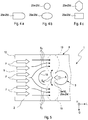
- FIG. 1 Illustrates a schematic representation of an example of an intake module 1 according to the invention with integrated exhaust gas recirculation.
- the intake module 1 comprises a housing 8 bounding a housing housing 8 made of a plastic.
- the housing 8 comprises a first housing wall 12 with at least one air inlet 9 and a second housing wall 13 with at least one fluid outlet 11.
- a virtual connecting line V between the at least one air inlet 9 and the at least one fluid outlet 11 defines a longitudinal direction L, which is a main flow direction which corresponds to the housing interior 4 fresh air F.
- the fresh air F can enter into the housing interior 4.
- a charge air cooler 15 is arranged, which is flowed through by the introduced into the housing interior 4 fresh air F.
- the fresh air F - which is typically compressed by an exhaust gas turbocharger, hot charge air - cooled by the charge air cooler 15.
- the intake module 1 further has a mixing chamber 2, which is part of the housing interior 4 and is limited by the intercooler 15 and the second housing wall 13.
- an exhaust gas distribution pipe 3 which extends along a transversely to the longitudinal direction L extending transverse direction Q of the housing 8 of the intake module 1.
- the exhaust gas distribution line 3 In the exhaust gas distribution line 3, at least one first and second exhaust gas outlet 5a, 5b are provided on a side of the exhaust gas distribution line 3 facing the air inlet 9, by means of which the exhaust gas A discharged from the internal combustion engine and flowing through the exhaust gas distribution line 3 flows into the mixing chamber 2 can be introduced.
- four such exhaust gas outlets 5a-5d are shown. Due to their high rigidity, a realization of the exhaust gas distribution line 3 in the form of an exhaust pipe is recommended. Of course, but deviating from such a design in the form of a tube, other suitable designs are also available.
- the longitudinal direction L can also be defined in other ways in variants of the example, for example by the main flow direction of the fresh air F in the mixing chamber 2, immediately before the fresh air F strikes the exhaust gas A introduced from the exhaust gas distribution line 3 into the mixing chamber 2.
- the intake module 1 comprises a provided on the exhaust gas distribution line 3 and in the manner of an opening 10 fluid passage 22. About this communicates an exhaust gas supply line 21 fluidly with the exhaust gas distribution line 3. About the exhaust gas supply line 21 is from the Internal combustion engine ejected and returned to this exhaust first introduced into the exhaust gas distribution line 3 and through this into the mixing chamber 2. Also, the exhaust gas supply line 21, analogous to the exhaust gas supply line 3, be designed as an exhaust pipe. In this case, said fluid passage 22 with respect to the transverse direction Q is arranged substantially centrally in the exhaust gas distribution line 3. Alternatively or additionally, the fluid passage 22 is also arranged substantially centrally in the mixing chamber 2 with respect to the transverse direction Q.
- exhaust gas A expelled from a combustion chamber of an internal combustion engine (not shown) is mixed with fresh air F drawn in from the environment U or with charge air charged, typically by an exhaust-gas turbocharger.
- the charge air or fresh air F is introduced via the air inlet 9 into the mixing chamber 2.
- the central longitudinal axis of the exhaust gas supply line 21 preferably extends in a plane E defined by the longitudinal direction L and a vertical direction H orthogonal to both the longitudinal and vertical directions L, Q. In the plane E is also the fluid passage 22.
- the exhaust gas supply line 21 thus also has a component in the high direction H.
- the exhaust gas supply line 21 extends from the plane of the FIG. 1 out. This clarifies, for example, the perspective view of the FIG. 6b , which will be explained in more detail below.
- the exhaust gas supply pipe 21 may also extend in a plane defined by the transverse direction Q and the high direction H in which the fluid passage 21 is disposed (not shown).
- FIG. 1 can a distance a 1 of the mixing chamber 2 in the transverse direction Q bounding the third housing wall 23 of the housing 8 to the exhaust gas supply line 21 in the transverse direction Q limiting and the third housing wall 23 facing the conduit wall 37a of the exhaust gas supply line 21 equal to a distance a 2 one of third housing wall 23 opposite, fourth housing wall 24 to one of the conduit wall 37 a opposite line side 37 b of the exhaust gas supply line 21 be.
- exhaust gas outlets 5a-5d are provided, which are arranged along the transverse direction Q at a distance from each other and the exhaust gas distribution line 3 fluidically with the mixing chamber 2 connect.
- the fluid passage 22 is arranged in the transverse direction Q between the exhaust gas outlets 5a, 5c and the exhaust gas outlets 5b, 5d.
- a different number of exhaust outlets 5a-5d can also be provided on the exhaust gas distribution line 3, a different number of exhaust outlets 5a-5d. It is conceivable, for example, to provide an even number of exhaust gas outlets 5a-5d and at least four such exhaust gas outlets a-5d.
- the arrangement of the outlets 5a-5d in the exhaust gas distribution line 3 can then take place such that, starting from the fluid passage 22 in and opposite to the transverse direction Q, the same number of exhaust gas outlets are respectively provided. In this way, the invention, symmetrical arrangement of the outlets 5a-5d is ensured relative to the fluid passage 22.
- FIG. 1 is defined by the longitudinal and the transverse direction L, Q is a cross-sectional plane of the intake module 1, in which the exhaust gas distribution line 3 and the exhaust gas supply line 21 to the exhaust gas supply line 21 symmetrical, in particular axisymmetric geometry.
- the exhaust gas distribution line 3 and the exhaust gas supply line 21 can be arranged symmetrically or axially symmetrically in the cross-sectional plane formed from the longitudinal and transverse directions L, Q, to an axis of symmetry S which runs along the longitudinal direction L and the exhaust gas Distribution line 3 with respect to the transverse direction Q centrally crosses.
- the symmetry axis S can also be defined by a virtual straight line (not shown) which runs parallel to the longitudinal direction and on which the fluid passage 22 is arranged.
- the exhaust gas distribution line 3 and the exhaust gas supply line 21 may have an inverted T-like geometry in said cross section.
- the number of fluid outlets 11 preferably corresponds to the number of cylinders of the internal combustion engine cooperating with the intake module 1 or is twice this number. That in the FIG. 1 As an example, intake module 1 with four fluid outlets 11 is designed for use with an internal combustion engine with four or eight cylinders.
- the realization of the intercooler unit 15 in the form of a coolant tube is particularly simple for a person skilled in the art.
- a coolant tube may have a respective coolant inlet or coolant outlet at the end.
- Technically more complex variants of the intercooler 15, however, may be designed as so-called tube bundle cooler or rib-tube cooler.
- Such a charge air cooler 15 may have a coolant path K, which in FIG. 1 is sketched only roughly schematic and for the cooling of the charge air cooler 15 by flowing fresh air F is flowed through by a coolant.
- the intercooler 15 may include a radiator housing 32 made of metal.
- the radiator housing 32 may include a housing wall 33 facing the exhaust gas distribution duct 3, in which, in the example of FIG.
- charge air outlets 38 are provided. After flowing through the intercooler 15 - this can be introduced into the housing interior 4 fresh air F through Ladelufteinlässe 36, which are provided in one of the housing wall 33 opposite housing wall 34 of the radiator housing 32 in the charge air cooler 15 - enters the fresh air F through the charge air outlets 38th again from the intercooler 15 and into the mixing chamber 2 a.
- the charge air cooler 15 may be provided with a coolant inlet 16 or coolant outlet 17 for introducing or discharging coolant into and out of the charge air cooler 15 with respect to the coolant path K on an end housing wall 35 outside the mixing chamber 2.
- FIG. 1 is the mixing chamber 2 between the charge air outlets 38 having housing wall 33 of the charge air cooler 15 and the second housing wall 13 of the housing 8 of the intake module 1, in which the fluid outlets 11 are arranged formed.
- the mixing chamber 2 results in the mixing chamber 2, a mixing section M within which the fresh air can mix with the exhaust gas A.
- the exhaust gas A flows in the direction of the charge air cooler 15, with the exhaust gas traversing a return flow path R.
- the mixing distance M is extended by the length of the return flow path R, whereby an improved mixing of the gases F, A is achieved.
- the guided through the intercooler 15 cooled fresh air has arranged in the intercooler 15 flow guides (not shown) at the exit from the charge air cooler 15 a very uniform, rectilinear flow.
- the exhaust flow directed countercurrently to the intercooler 15 reaches the intercooler 15 with an optimum design, without the exhaust gas A penetrating into the intercooler 15.
- the mixing section M on which there is a mixing of the fresh air F with the exhaust gas A, increased, resulting in improved mixing of the gases.
- a distance d 1 between the exhaust gas distribution line 3 and the intercooler 15 is selected such that the outflowing exhaust gas A just flows into the intercooler 15, but no longer penetrates into the intercooler 15.
- the introduced exhaust gas A sets the distance d 1 between the exhaust gas outlets 5a-5d and intercooler 15 twice, whereby the exhaust gas A already flows against the charge air flow when flowing against it and the mixing continues on the return flow up to the exhaust gas distribution line 3 ,
- the exhaust gas A continues to mix with the fresh air F, whereby a very homogeneous mixing is achieved before the gas mixture flows through the leading to the individual cylinder fluid outlets 11.
- an undesired contamination of the intercooler 15 is prevented and formed a maximum mixing distance with a homogeneous mixing of the gases.
- the distance d 1 between the exhaust gas distribution line 3 and the intercooler 15 about 2 cm to - 15 cm, preferably about 4 to 5 cm.
- the introduction of the exhaust gas A into the mixing chamber 2 of the intake module 1 takes place with a flow direction S A opposite to the flow direction S F fresh air F.
- This allows a comparison with conventional intake modules improved mixing of the exhaust A with fresh air F even in the smallest space.
- the fresh air F thus mixed with exhaust gas A can be homogeneously introduced into the internal combustion engine, which considerably improves its efficiency.
- FIG. 1 In order to achieve the greatest possible mixing of fresh air F and exhaust gas A, it is recommended accordingly FIG. 1 to place the exhaust gas distribution pipe 3 in the housing 8 so that the exhaust gas outlets 5a-5d face the air inlet 9. Then, the exhaust gas A emerging from the exhaust gas distribution line 3 flows as desired in a substantially opposite direction S A to the fresh air F into the mixing chamber 2, which favors a homogeneous mixing process of fresh air F and exhaust gas A.
- the flow direction S A runs opposite to the flow direction S F. Because a good mixing of fresh air F with exhaust gas A is just achieved when air and exhaust molecules under a Angles of as close as possible to 180 °. In this case, the two directions S A , S F form an angle of 180 ° to one another. Other preferred angle values for the angle between the flow directions S A , S F may be defined by an angular interval of 160 ° to 200 or of 170 ° to 190 °.
- the distance d 1 between the exhaust gas distribution line 3 and the charge air cooler 15 corresponds to a distance d 2 of the exhaust gas distribution line 3 to the second housing wall 13, in which the fluid outlets 11 are arranged to the cylinders (not shown).
- the mixing length in the mixing chamber 2 can be significantly extended.
- the distance d 1 between the exhaust gas distribution line 3 and the intercooler 15 can be greater (not shown) or, as in FIG. 1 shown, be smaller than the distance d 2 between the exhaust gas distribution line 3 and said second housing wall 13. According to the interpretation, such a multiplication, z. B. doubling or tripling, the mixing length can be achieved.
- intercooler 15 and exhaust gas distribution line 3 can be integrally formed on the housing 8 of the mixing chamber 3.
- intercooler 15 and exhaust distribution line 3 can also be screwed or welded to the housing 8.
- each exhaust gas outlet 5a-5d is provided in the exhaust gas distribution pipe 3.
- a number of exhaust gas outlet openings is provided, which is greater than the number of cylinders of the intake module 1 using the internal combustion engine.
- the number of exhaust gas outlets is preferably 5a-5d is a multiple of the number of cylinders or more.
- the use of eight, but also of 16 exhaust outlets is conceivable when the intake module 1 is used in a four-cylinder internal combustion engine.
- any number of exhaust gas outlet openings 5a-5d not individually assigned to the individual cylinders may also be provided.
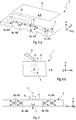
- FIG. 2 shows the exhaust gas distribution line 3 in a separate representation.
- the exhaust gas outlets 5a-5d each include an exhaust gas outlet opening 25a-25d with an exhaust gas deflecting element 27a-27d projecting inwardly into the exhaust gas distribution pipe 3.
- the four exhaust baffles 27a-27d serve to deflect the exhaust gas flowing through the exhaust gas distribution pipe 3 to the exhaust gas outlet ports 25a-d associated therewith. In this way, an undesirable buildup of exhaust gas A at the two ends 26a, 26b of the exhaust gas distribution line 3 and an associated uneven distribution of the exhaust gas A to the individual exhaust gas outlets 5a-5d largely or even completely avoided.
- the exhaust gas deflecting elements 27a-27d shown can be dispensed with at individual exhaust gas outlets 5a-5d, in particular at the exhaust gas outlets 5a, 5d adjacent the two ends 26a, 26b of the exhaust gas distribution line 3 in the transverse direction Q (not shown).
- FIG. 3b shows in addition to the presentation of FIG. 3a the exhaust gas distribution pipe 3 in a cross section of the exhaust gas distribution pipe 3 defined orthogonal to the transverse direction Q.
- the deflection element 27b has a first end section 29a, by means of which it is mounted on the first edge section 28a of the opening edge 28.
- a second, free end portion 29b of the exhaust gas deflector 27b opposite the first end portion 29a in cross section projects inwardly into the exhaust gas distribution pipe 3 and toward the exhaust gas supply pipe 21 from the opening edge 28.
- the exhaust deflectors 27 a - 27 d may be integrally formed on the exhaust gas distribution pipe 3.
- exhaust gas outlet openings 25a-25d With regard to the geometric configuration of the exhaust gas outlet openings 25a-25d, the person skilled in the art has various design options, which are shown by way of example in the rough-schematic representation of FIG FIG. 4 are shown. Exhaust gas outlet openings 25a-25d, which have approximately a round, in particular circular, or an elliptical opening contour, are particularly easy to realize in technical terms, cf. For this FIG. 4b , Alternatively, one is recommended in the Figure 4c shown realization with a polygonal opening contour, such as a rectangular and in particular a square opening contour. Also in the FIG. 4a shown combination of a rectangle and a semicircle is conceivable.
- FIG. 5 schematically illustrated attachment of a deflector 18 in the mixing chamber 2, in the flow direction S F of the fresh air F between the air inlet 9 and the exhaust gas distribution line 3, see this Fig. 1 .
- the placement of such a deflecting element 18, for example in the manner of a shield, may take place in such a way that it diverts at least part of the fresh air F introduced into the mixing chamber 3 before it strikes the exhaust gas A.
- the deflector 18 has in the in FIG. 5 shown longitudinal section of the exhaust pipe 3 along the transverse direction Q the shape of a circle segment and causes a deflection of the introduced into the mixing chamber 3 exhaust gas A.
- the fresh air F is channeled to edge regions of the housing 8 out.
- fresh air F and exhaust gas A have opposite directions of flow S F , S A when introduced into the mixing chamber 2, but not in the actual mixing in the mixing chamber 2 in the mixing chamber 2 due to the deflecting properties of the deflecting element 18 FIG. 5 with 19 designated area.
- the deflecting element 18 may generally have a geometry curved toward the respective exhaust gas outlet 5a-5d, for example circular segment-like geometry.
- FIG. 6a shows the intake module 1 according to the invention in a perspective view, the FIG. 6b in a longitudinal section along the longitudinal direction L of the intake module 1.
- a vertical direction H of the intake module is defined.
- the fluid passage 22 is on a the exhaust gas distribution line 3 in the vertical direction H limiting upper wall portion 6 of the exhaust gas distribution line 3 is provided.
- the exhaust gas supply line 21 may protrude at least in sections in the vertical direction H from the upper wall portion 6 of the exhaust gas distribution line 3.
- an additional exhaust gas outlet 7 may be provided in the exhaust gas distribution line 3 along the transverse direction Q in the area of the fluid passage 22 between the exhaust gas outlets 5a-5d.
Landscapes
- Engineering & Computer Science (AREA)
- Chemical & Material Sciences (AREA)
- Combustion & Propulsion (AREA)
- Mechanical Engineering (AREA)
- General Engineering & Computer Science (AREA)
- Manufacturing & Machinery (AREA)
- Physics & Mathematics (AREA)
- Thermal Sciences (AREA)
- Exhaust-Gas Circulating Devices (AREA)
Claims (11)
- Module d'aspiration (1) avec recirculation de gaz d'échappement intégrée,- avec un boîtier (8) limitant un intérieur de boîtier (4), lequel présente une première paroi de boîtier (12) avec au moins une entrée d'air (9) et une deuxième paroi de boîtier (13) avec au moins une sortie de fluide (11),- avec un refroidisseur d'air de suralimentation (15) agencé dans l'intérieur de boîtier (4),- avec une chambre de mélange (2), qui fait partie de l'intérieur de boîtier (4) et est limitée par le refroidisseur d'air de suralimentation (15) et la deuxième paroi de boîtier (13),- avec une conduite de distribution de gaz d'échappement (3) agencée dans la chambre de mélange (2), laquelle s'étend le long d'un sens transversal (Q), dans lequel au moins une première et une deuxième sortie de gaz d'échappement (5a-5d) sont prévues dans la conduite de distribution de gaz d'échappement (3) sur un côté de la conduite de distribution de gaz d'échappement (3) tourné vers l'entrée d'air (9), au moyen desquelles le gaz d'échappement (A) évacué du moteur à combustion interne et traversant la conduite de distribution de gaz d'échappement (3) peut être introduit dans la chambre de mélange (2),- avec une conduite d'alimentation de gaz d'échappement (21) reliée fluidiquement par le biais d'un passage de fluide (22) prévu au niveau de la conduite de distribution de gaz d'échappement (3) à celui-ci,
caractérisé en ce que- le passage de fluide (22) est agencé par rapport au sens transversal (Q) sensiblement au milieu dans la conduite de distribution de gaz d'échappement (3) et/ou dans la chambre de mélange (2),- le refroidisseur d'air de suralimentation (15) et la conduite de distribution de gaz d'échappement (3) sont agencés dans le boîtier (8) de telle sorte que le sens d'écoulement (SA) du gaz d'échappement (A) introduit dans la chambre de mélange (2) s'étend de manière sensiblement opposée au sens d'écoulement (SF) de l'air frais (F) introduit dans la chambre de mélange (2), si bien que les deux sens (SA, SF) forment un angle de sensiblement 180° l'un par rapport à l'autre. - Module d'aspiration selon la revendication 1,
caractérisé en ce que- un sens longitudinal (L) est défini par une ligne de liaison virtuelle entre l'au moins une entrée d'air (9) et l'au moins une sortie de fluide (11), dans lequel le sens transversal (Q) s'étend orthogonalement au sens longitudinal (L),- la conduite d'alimentation de gaz d'échappement (21) s'étend soit dans un plan (E), qui est défini par le sens longitudinal (L) et un sens de la hauteur (H) s'étendant orthogonalement aussi bien au sens longitudinal qu'au sens transversal (L, Q) et dans lequel le passage de fluide (22) est agencé, soit que la conduite d'alimentation de gaz d'échappement (21) s'étend dans un plan défini par le sens transversal (Q) et le sens de la hauteur (H), dans lequel le passage de fluide (22) est agencé. - Module d'aspiration selon la revendication 1 ou 2,
le refroidisseur d'air de suralimentation (15) et la conduite de distribution de gaz d'échappement (3) sont agencés dans le boîtier (8) de telle sorte que le gaz d'échappement (A) introduit dans la chambre de mélange (2) n'entre plus dans le refroidisseur d'air de suralimentation (15). - Module d'aspiration selon l'une quelconque des revendications précédentes,
caractérisé en ce que
une distance (d1) entre la conduite de distribution de gaz d'échappement (3) et le refroidisseur d'air de suralimentation (15) est sensiblement égale à l'une distance (d2) entre la conduite de distribution de gaz d'échappement (3) et la deuxième paroi de boîtier (3) et est supérieure ou inférieure à cette distance (d2). - Module d'aspiration selon l'une quelconque des revendications précédentes,
caractérisé en ce que
le refroidisseur d'air de suralimentation (15) est réalisé en tant que refroidisseur de faisceau de tubes ou en tant que refroidisseur de tube nervure avec au moins un chemin de réfrigérant (K), lequel présente une entrée de réfrigérant (16) et une sortie de réfrigérant (17) au niveau d'une paroi de boîtier frontale (23) et est agencé par rapport au chemin de réfrigérant (K) de manière sensiblement parallèle à la conduite de distribution de gaz d'échappement (3) dans la chambre de mélange (2). - Module d'aspiration selon l'une quelconque des revendications précédentes,
caractérisé en ce que
le passage de fluide (22) est agencé dans le sens transversal (Q) entre la première et la deuxième sortie de gaz d'échappement (5a, 5b). - Module d'aspiration selon l'une quelconque des revendications précédentes,
caractérisé en ce que
un nombre pair de sorties de gaz d'échappement (5a-5d) et au moins quatre de ces sorties de gaz d'échappement (5a-5d) sont prévus dans la conduite de distribution de gaz d'échappement (3), dans lequel respectivement le même nombre de sorties de gaz d'échappement (5a-5d) est prévu dans la conduite de distribution de gaz d'échappement (3) partant du passage de fluide (21) dans et à l'opposé du sens transversal (Q). - Module d'aspiration selon l'une quelconque des revendications précédentes,
caractérisé en ce que- une section transversale du module d'aspiration (1) est définie par le sens longitudinal et le sens transversal (L, Q),- la conduite de distribution de gaz d'échappement (3) et la conduite d'alimentation de gaz d'échappement (21) et les sorties de gaz d'échappement (5a-5d) sont agencées dans cette section transversale de manière symétrique, en particulier symétrique axiale, par rapport à un axe de symétrie, lequel s'étend le long du sens longitudinal (L) et coupe la conduite de distribution de gaz d'échappement (3) au milieu par rapport au sens transversal (Q). - Module d'aspiration selon l'une quelconque des revendications précédentes,
caractérisé en ce que
le passage de fluide (22) est prévu sur une section de paroi supérieure (6) de la conduite de distribution de gaz d'échappement (3) limitant la conduite de distribution de gaz d'échappement (3) dans le sens de la hauteur (H). - Module d'aspiration selon la revendication 9,
caractérisé en ce que
la conduite d'alimentation de gaz d'échappement (21) fait saillie au moins par tronçon dans le sens de la hauteur (H) de la section de paroi supérieure (6) de la conduite de distribution de gaz d'échappement (3). - Module d'aspiration selon l'une quelconque des revendications précédentes,
caractérisé en ce que
une sortie de gaz d'échappement supplémentaire (7) est prévue dans la conduite de distribution de gaz d'échappement (3) le long du sens transversal (Q) à hauteur du passage de fluide.
Applications Claiming Priority (2)
| Application Number | Priority Date | Filing Date | Title |
|---|---|---|---|
| DE102014214591.0A DE102014214591A1 (de) | 2014-07-24 | 2014-07-24 | Ansaugmodul mit integrierter Abgasrückführung für eine Brennkraftmaschine |
| PCT/EP2015/061965 WO2016012129A1 (fr) | 2014-07-24 | 2015-05-29 | Module d'aspiration pourvu d'une recirculation de gaz d'échappement intégrée pour moteur à combustion interne |
Publications (2)
| Publication Number | Publication Date |
|---|---|
| EP3172425A1 EP3172425A1 (fr) | 2017-05-31 |
| EP3172425B1 true EP3172425B1 (fr) | 2018-10-17 |
Family
ID=53200014
Family Applications (1)
| Application Number | Title | Priority Date | Filing Date |
|---|---|---|---|
| EP15723982.3A Not-in-force EP3172425B1 (fr) | 2014-07-24 | 2015-05-29 | Module d'aspiration pourvu d'une recirculation de gaz d'échappement intégrée pour moteur à combustion interne |
Country Status (3)
| Country | Link |
|---|---|
| EP (1) | EP3172425B1 (fr) |
| DE (1) | DE102014214591A1 (fr) |
| WO (1) | WO2016012129A1 (fr) |
Families Citing this family (2)
| Publication number | Priority date | Publication date | Assignee | Title |
|---|---|---|---|---|
| JP6677202B2 (ja) * | 2017-03-28 | 2020-04-08 | トヨタ自動車株式会社 | インテークマニホールド |
| CN118959188A (zh) * | 2024-10-17 | 2024-11-15 | 湖南敏行汽车科技有限公司 | 一种发动机进气结构 |
Family Cites Families (16)
| Publication number | Priority date | Publication date | Assignee | Title |
|---|---|---|---|---|
| JPS57171058A (en) * | 1981-04-11 | 1982-10-21 | Nissan Motor Co Ltd | Distributing device for exhaust gas recirculation system |
| JPS5915976U (ja) * | 1982-07-22 | 1984-01-31 | 住友金属工業株式会社 | 磁粉探傷機の接地検出装置 |
| US5957116A (en) | 1997-08-28 | 1999-09-28 | Cummins Engine Company, Inc. | Integrated and separable EGR distribution manifold |
| DE10004552A1 (de) | 2000-02-02 | 2001-08-09 | Mann & Hummel Filter | Saugrohr mit integrierter Abgasrückführung |
| JP2003262164A (ja) * | 2002-03-07 | 2003-09-19 | Denso Corp | 内燃機関用吸気装置 |
| DE10354129A1 (de) | 2003-11-19 | 2005-06-23 | Mahle Filtersysteme Gmbh | Sauganlage für eine Brennkraftmaschine |
| DE102006048485A1 (de) * | 2006-10-11 | 2008-04-17 | Behr Gmbh & Co. Kg | Vorrichtung zur Ladeluftkühlung für einen Verbrennungsmotor, System mit einer Vorrichtung zur Ladeluftkühlung |
| DE102007009354A1 (de) * | 2007-02-23 | 2008-09-04 | Mahle International Gmbh | Frischgasmodul für eine Frischgasanlage |
| DE102007035556A1 (de) * | 2007-07-28 | 2009-01-29 | Daimler Ag | Mischvorrichtung zum Zumischen eines Abgasrückführstroms in einen Ladeluftstrom einer Brennkraftmaschine |
| DE202009001782U1 (de) * | 2009-02-12 | 2010-07-08 | Mann+Hummel Gmbh | Abgasansaugvorrichtung |
| FR2946698B1 (fr) * | 2009-06-15 | 2015-08-28 | Valeo Systemes Thermiques | Dispositif de melange d'un flux de gaz d'admission et d'un flux de gaz d'echappement recircules |
| FR2946699B1 (fr) * | 2009-06-15 | 2015-06-26 | Valeo Systemes Thermiques | Dispositif de melange d'un flux de gaz d'admission et d'un flux de gaz d'echappement recircules comprenant des moyens d'injection de gaz recircules |
| FR2958336B1 (fr) * | 2010-03-31 | 2013-03-15 | Valeo Systemes Thermiques | Collecteur de repartition de gaz dans la culasse d'un moteur avec melange des gaz d'echappement recircules a contre-courant des gaz d'admission. |
| FR2965306B1 (fr) * | 2010-09-27 | 2012-09-14 | Valeo Systemes Thermiques | Dispositif de melange d'un flux de gaz d'admission et d'un flux de gaz d'echappement recircules comprenant des moyens d'isolation du flux de gaz d'echappement recircules |
| JP2012097675A (ja) * | 2010-11-02 | 2012-05-24 | Aisin Seiki Co Ltd | 内燃機関の吸気装置 |
| FR2967215B1 (fr) * | 2010-11-08 | 2016-01-01 | Valeo Systemes Thermiques | Collecteur de repartition de gaz et module d'admission de gaz correspondant |
-
2014
- 2014-07-24 DE DE102014214591.0A patent/DE102014214591A1/de not_active Withdrawn
-
2015
- 2015-05-29 WO PCT/EP2015/061965 patent/WO2016012129A1/fr not_active Ceased
- 2015-05-29 EP EP15723982.3A patent/EP3172425B1/fr not_active Not-in-force
Non-Patent Citations (1)
| Title |
|---|
| None * |
Also Published As
| Publication number | Publication date |
|---|---|
| EP3172425A1 (fr) | 2017-05-31 |
| DE102014214591A1 (de) | 2016-01-28 |
| WO2016012129A1 (fr) | 2016-01-28 |
Similar Documents
| Publication | Publication Date | Title |
|---|---|---|
| EP3216992B1 (fr) | Mélangeur | |
| EP3027881B1 (fr) | Module d'aspiration destiné à un moteur à combustion interne | |
| DE112014003949B4 (de) | Abgasreinigungsvorrichtung für Verbrennungsmotor | |
| DE102016006606B4 (de) | Abgaskrümmer | |
| DE112010002589B4 (de) | Abgasstrang mit Einspritzsystem | |
| DE102012016423B3 (de) | Abgasanlage mit Misch- und oder Verdampfungseinrichtung | |
| EP2610457B1 (fr) | Dispositif de traitement des gaz d'échappement | |
| EP2199722B1 (fr) | Refroidisseur pour gaz d'échappement | |
| DE102011055868A1 (de) | Windstrom-konzentrations-führungs-vorrichtung und motorraum-layout mit derselben | |
| DE102016119306A1 (de) | Vorrichtung zum Vermischen von Fluidströmen | |
| DE112015001899T5 (de) | Abgaswärmetauscher | |
| EP1203142A1 (fr) | Moteur a combustion interne pourvu d'un systeme d'insufflation d'air secondaire | |
| EP1995463B1 (fr) | Compresseur à plusieurs étages dotée d'un dispositif de refroidissement | |
| EP3172425B1 (fr) | Module d'aspiration pourvu d'une recirculation de gaz d'échappement intégrée pour moteur à combustion interne | |
| DE10393644T5 (de) | Kraftstoffeinspritzdüsenpassstück | |
| DE112022006302T5 (de) | Scr-mischer und motor | |
| DE102012014528A1 (de) | Mehrstufiger Plattenmischer | |
| EP2161428A1 (fr) | Refroidisseur d'air de suralimentation, notamment pour grands moteurs | |
| CH715208A1 (de) | System zum Einbringen eines Reduktionsmittels in einen Abgasstrom. | |
| DE19745068C1 (de) | Großdieselmotor | |
| DE102004025254A1 (de) | Brennkraftmaschine mit Abgasrückführung | |
| DE19745067A1 (de) | Großdieselmotor | |
| DE102008040293B4 (de) | Abgasanlage für einen Verbrennungsmotor | |
| DE102019116504A1 (de) | Mischvorrichtung zur Einmischung eines Fluids in einen Abgasmassenstrom | |
| DE102009026467A1 (de) | Anordnung zum Eindosieren von Additiv |
Legal Events
| Date | Code | Title | Description |
|---|---|---|---|
| STAA | Information on the status of an ep patent application or granted ep patent |
Free format text: STATUS: THE INTERNATIONAL PUBLICATION HAS BEEN MADE |
|
| PUAI | Public reference made under article 153(3) epc to a published international application that has entered the european phase |
Free format text: ORIGINAL CODE: 0009012 |
|
| STAA | Information on the status of an ep patent application or granted ep patent |
Free format text: STATUS: REQUEST FOR EXAMINATION WAS MADE |
|
| 17P | Request for examination filed |
Effective date: 20170111 |
|
| AK | Designated contracting states |
Kind code of ref document: A1 Designated state(s): AL AT BE BG CH CY CZ DE DK EE ES FI FR GB GR HR HU IE IS IT LI LT LU LV MC MK MT NL NO PL PT RO RS SE SI SK SM TR |
|
| AX | Request for extension of the european patent |
Extension state: BA ME |
|
| DAV | Request for validation of the european patent (deleted) | ||
| DAX | Request for extension of the european patent (deleted) | ||
| REG | Reference to a national code |
Ref country code: DE Ref legal event code: R079 Ref document number: 502015006468 Country of ref document: DE Free format text: PREVIOUS MAIN CLASS: F02M0035100000 Ipc: F02M0026190000 |
|
| RIC1 | Information provided on ipc code assigned before grant |
Ipc: F02M 26/19 20160101AFI20180322BHEP Ipc: F02B 29/04 20060101ALI20180322BHEP Ipc: F02M 35/112 20060101ALI20180322BHEP Ipc: F02M 35/10 20060101ALI20180322BHEP |
|
| GRAP | Despatch of communication of intention to grant a patent |
Free format text: ORIGINAL CODE: EPIDOSNIGR1 |
|
| STAA | Information on the status of an ep patent application or granted ep patent |
Free format text: STATUS: GRANT OF PATENT IS INTENDED |
|
| INTG | Intention to grant announced |
Effective date: 20180507 |
|
| GRAS | Grant fee paid |
Free format text: ORIGINAL CODE: EPIDOSNIGR3 |
|
| GRAA | (expected) grant |
Free format text: ORIGINAL CODE: 0009210 |
|
| STAA | Information on the status of an ep patent application or granted ep patent |
Free format text: STATUS: THE PATENT HAS BEEN GRANTED |
|
| AK | Designated contracting states |
Kind code of ref document: B1 Designated state(s): AL AT BE BG CH CY CZ DE DK EE ES FI FR GB GR HR HU IE IS IT LI LT LU LV MC MK MT NL NO PL PT RO RS SE SI SK SM TR |
|
| REG | Reference to a national code |
Ref country code: GB Ref legal event code: FG4D Free format text: NOT ENGLISH |
|
| REG | Reference to a national code |
Ref country code: CH Ref legal event code: EP |
|
| REG | Reference to a national code |
Ref country code: IE Ref legal event code: FG4D Free format text: LANGUAGE OF EP DOCUMENT: GERMAN |
|
| REG | Reference to a national code |
Ref country code: DE Ref legal event code: R096 Ref document number: 502015006468 Country of ref document: DE Ref country code: AT Ref legal event code: REF Ref document number: 1054329 Country of ref document: AT Kind code of ref document: T Effective date: 20181115 |
|
| REG | Reference to a national code |
Ref country code: NL Ref legal event code: MP Effective date: 20181017 |
|
| REG | Reference to a national code |
Ref country code: LT Ref legal event code: MG4D |
|
| PG25 | Lapsed in a contracting state [announced via postgrant information from national office to epo] |
Ref country code: NL Free format text: LAPSE BECAUSE OF FAILURE TO SUBMIT A TRANSLATION OF THE DESCRIPTION OR TO PAY THE FEE WITHIN THE PRESCRIBED TIME-LIMIT Effective date: 20181017 |
|
| PG25 | Lapsed in a contracting state [announced via postgrant information from national office to epo] |
Ref country code: LV Free format text: LAPSE BECAUSE OF FAILURE TO SUBMIT A TRANSLATION OF THE DESCRIPTION OR TO PAY THE FEE WITHIN THE PRESCRIBED TIME-LIMIT Effective date: 20181017 Ref country code: ES Free format text: LAPSE BECAUSE OF FAILURE TO SUBMIT A TRANSLATION OF THE DESCRIPTION OR TO PAY THE FEE WITHIN THE PRESCRIBED TIME-LIMIT Effective date: 20181017 Ref country code: LT Free format text: LAPSE BECAUSE OF FAILURE TO SUBMIT A TRANSLATION OF THE DESCRIPTION OR TO PAY THE FEE WITHIN THE PRESCRIBED TIME-LIMIT Effective date: 20181017 Ref country code: PL Free format text: LAPSE BECAUSE OF FAILURE TO SUBMIT A TRANSLATION OF THE DESCRIPTION OR TO PAY THE FEE WITHIN THE PRESCRIBED TIME-LIMIT Effective date: 20181017 Ref country code: BG Free format text: LAPSE BECAUSE OF FAILURE TO SUBMIT A TRANSLATION OF THE DESCRIPTION OR TO PAY THE FEE WITHIN THE PRESCRIBED TIME-LIMIT Effective date: 20190117 Ref country code: HR Free format text: LAPSE BECAUSE OF FAILURE TO SUBMIT A TRANSLATION OF THE DESCRIPTION OR TO PAY THE FEE WITHIN THE PRESCRIBED TIME-LIMIT Effective date: 20181017 Ref country code: IS Free format text: LAPSE BECAUSE OF FAILURE TO SUBMIT A TRANSLATION OF THE DESCRIPTION OR TO PAY THE FEE WITHIN THE PRESCRIBED TIME-LIMIT Effective date: 20190217 Ref country code: FI Free format text: LAPSE BECAUSE OF FAILURE TO SUBMIT A TRANSLATION OF THE DESCRIPTION OR TO PAY THE FEE WITHIN THE PRESCRIBED TIME-LIMIT Effective date: 20181017 Ref country code: NO Free format text: LAPSE BECAUSE OF FAILURE TO SUBMIT A TRANSLATION OF THE DESCRIPTION OR TO PAY THE FEE WITHIN THE PRESCRIBED TIME-LIMIT Effective date: 20190117 |
|
| PG25 | Lapsed in a contracting state [announced via postgrant information from national office to epo] |
Ref country code: GR Free format text: LAPSE BECAUSE OF FAILURE TO SUBMIT A TRANSLATION OF THE DESCRIPTION OR TO PAY THE FEE WITHIN THE PRESCRIBED TIME-LIMIT Effective date: 20190118 Ref country code: RS Free format text: LAPSE BECAUSE OF FAILURE TO SUBMIT A TRANSLATION OF THE DESCRIPTION OR TO PAY THE FEE WITHIN THE PRESCRIBED TIME-LIMIT Effective date: 20181017 Ref country code: PT Free format text: LAPSE BECAUSE OF FAILURE TO SUBMIT A TRANSLATION OF THE DESCRIPTION OR TO PAY THE FEE WITHIN THE PRESCRIBED TIME-LIMIT Effective date: 20190217 Ref country code: AL Free format text: LAPSE BECAUSE OF FAILURE TO SUBMIT A TRANSLATION OF THE DESCRIPTION OR TO PAY THE FEE WITHIN THE PRESCRIBED TIME-LIMIT Effective date: 20181017 Ref country code: SE Free format text: LAPSE BECAUSE OF FAILURE TO SUBMIT A TRANSLATION OF THE DESCRIPTION OR TO PAY THE FEE WITHIN THE PRESCRIBED TIME-LIMIT Effective date: 20181017 |
|
| REG | Reference to a national code |
Ref country code: DE Ref legal event code: R097 Ref document number: 502015006468 Country of ref document: DE |
|
| PG25 | Lapsed in a contracting state [announced via postgrant information from national office to epo] |
Ref country code: DK Free format text: LAPSE BECAUSE OF FAILURE TO SUBMIT A TRANSLATION OF THE DESCRIPTION OR TO PAY THE FEE WITHIN THE PRESCRIBED TIME-LIMIT Effective date: 20181017 Ref country code: IT Free format text: LAPSE BECAUSE OF FAILURE TO SUBMIT A TRANSLATION OF THE DESCRIPTION OR TO PAY THE FEE WITHIN THE PRESCRIBED TIME-LIMIT Effective date: 20181017 Ref country code: CZ Free format text: LAPSE BECAUSE OF FAILURE TO SUBMIT A TRANSLATION OF THE DESCRIPTION OR TO PAY THE FEE WITHIN THE PRESCRIBED TIME-LIMIT Effective date: 20181017 |
|
| PLBE | No opposition filed within time limit |
Free format text: ORIGINAL CODE: 0009261 |
|
| STAA | Information on the status of an ep patent application or granted ep patent |
Free format text: STATUS: NO OPPOSITION FILED WITHIN TIME LIMIT |
|
| PG25 | Lapsed in a contracting state [announced via postgrant information from national office to epo] |
Ref country code: RO Free format text: LAPSE BECAUSE OF FAILURE TO SUBMIT A TRANSLATION OF THE DESCRIPTION OR TO PAY THE FEE WITHIN THE PRESCRIBED TIME-LIMIT Effective date: 20181017 Ref country code: SK Free format text: LAPSE BECAUSE OF FAILURE TO SUBMIT A TRANSLATION OF THE DESCRIPTION OR TO PAY THE FEE WITHIN THE PRESCRIBED TIME-LIMIT Effective date: 20181017 Ref country code: SM Free format text: LAPSE BECAUSE OF FAILURE TO SUBMIT A TRANSLATION OF THE DESCRIPTION OR TO PAY THE FEE WITHIN THE PRESCRIBED TIME-LIMIT Effective date: 20181017 Ref country code: EE Free format text: LAPSE BECAUSE OF FAILURE TO SUBMIT A TRANSLATION OF THE DESCRIPTION OR TO PAY THE FEE WITHIN THE PRESCRIBED TIME-LIMIT Effective date: 20181017 |
|
| 26N | No opposition filed |
Effective date: 20190718 |
|
| PG25 | Lapsed in a contracting state [announced via postgrant information from national office to epo] |
Ref country code: SI Free format text: LAPSE BECAUSE OF FAILURE TO SUBMIT A TRANSLATION OF THE DESCRIPTION OR TO PAY THE FEE WITHIN THE PRESCRIBED TIME-LIMIT Effective date: 20181017 |
|
| REG | Reference to a national code |
Ref country code: CH Ref legal event code: PL |
|
| GBPC | Gb: european patent ceased through non-payment of renewal fee |
Effective date: 20190529 |
|
| PG25 | Lapsed in a contracting state [announced via postgrant information from national office to epo] |
Ref country code: LI Free format text: LAPSE BECAUSE OF NON-PAYMENT OF DUE FEES Effective date: 20190531 Ref country code: MC Free format text: LAPSE BECAUSE OF FAILURE TO SUBMIT A TRANSLATION OF THE DESCRIPTION OR TO PAY THE FEE WITHIN THE PRESCRIBED TIME-LIMIT Effective date: 20181017 Ref country code: CH Free format text: LAPSE BECAUSE OF NON-PAYMENT OF DUE FEES Effective date: 20190531 |
|
| REG | Reference to a national code |
Ref country code: BE Ref legal event code: MM Effective date: 20190531 |
|
| PG25 | Lapsed in a contracting state [announced via postgrant information from national office to epo] |
Ref country code: LU Free format text: LAPSE BECAUSE OF NON-PAYMENT OF DUE FEES Effective date: 20190529 |
|
| PG25 | Lapsed in a contracting state [announced via postgrant information from national office to epo] |
Ref country code: TR Free format text: LAPSE BECAUSE OF FAILURE TO SUBMIT A TRANSLATION OF THE DESCRIPTION OR TO PAY THE FEE WITHIN THE PRESCRIBED TIME-LIMIT Effective date: 20181017 |
|
| PG25 | Lapsed in a contracting state [announced via postgrant information from national office to epo] |
Ref country code: GB Free format text: LAPSE BECAUSE OF NON-PAYMENT OF DUE FEES Effective date: 20190529 Ref country code: IE Free format text: LAPSE BECAUSE OF NON-PAYMENT OF DUE FEES Effective date: 20190529 |
|
| PG25 | Lapsed in a contracting state [announced via postgrant information from national office to epo] |
Ref country code: BE Free format text: LAPSE BECAUSE OF NON-PAYMENT OF DUE FEES Effective date: 20190531 |
|
| PG25 | Lapsed in a contracting state [announced via postgrant information from national office to epo] |
Ref country code: CY Free format text: LAPSE BECAUSE OF FAILURE TO SUBMIT A TRANSLATION OF THE DESCRIPTION OR TO PAY THE FEE WITHIN THE PRESCRIBED TIME-LIMIT Effective date: 20181017 |
|
| REG | Reference to a national code |
Ref country code: AT Ref legal event code: MM01 Ref document number: 1054329 Country of ref document: AT Kind code of ref document: T Effective date: 20200529 |
|
| PG25 | Lapsed in a contracting state [announced via postgrant information from national office to epo] |
Ref country code: HU Free format text: LAPSE BECAUSE OF FAILURE TO SUBMIT A TRANSLATION OF THE DESCRIPTION OR TO PAY THE FEE WITHIN THE PRESCRIBED TIME-LIMIT; INVALID AB INITIO Effective date: 20150529 Ref country code: MT Free format text: LAPSE BECAUSE OF FAILURE TO SUBMIT A TRANSLATION OF THE DESCRIPTION OR TO PAY THE FEE WITHIN THE PRESCRIBED TIME-LIMIT Effective date: 20181017 |
|
| PGFP | Annual fee paid to national office [announced via postgrant information from national office to epo] |
Ref country code: DE Payment date: 20210527 Year of fee payment: 7 Ref country code: FR Payment date: 20210526 Year of fee payment: 7 |
|
| PG25 | Lapsed in a contracting state [announced via postgrant information from national office to epo] |
Ref country code: AT Free format text: LAPSE BECAUSE OF NON-PAYMENT OF DUE FEES Effective date: 20200529 |
|
| PG25 | Lapsed in a contracting state [announced via postgrant information from national office to epo] |
Ref country code: MK Free format text: LAPSE BECAUSE OF FAILURE TO SUBMIT A TRANSLATION OF THE DESCRIPTION OR TO PAY THE FEE WITHIN THE PRESCRIBED TIME-LIMIT Effective date: 20181017 |
|
| REG | Reference to a national code |
Ref country code: DE Ref legal event code: R119 Ref document number: 502015006468 Country of ref document: DE |
|
| PG25 | Lapsed in a contracting state [announced via postgrant information from national office to epo] |
Ref country code: FR Free format text: LAPSE BECAUSE OF NON-PAYMENT OF DUE FEES Effective date: 20220531 |
|
| PG25 | Lapsed in a contracting state [announced via postgrant information from national office to epo] |
Ref country code: DE Free format text: LAPSE BECAUSE OF NON-PAYMENT OF DUE FEES Effective date: 20221201 |