EP3171682A1 - Verteilungssystem mit einer elektronischen sicherungsklemme und zumindest einer ersten reihenklemme - Google Patents
Verteilungssystem mit einer elektronischen sicherungsklemme und zumindest einer ersten reihenklemme Download PDFInfo
- Publication number
- EP3171682A1 EP3171682A1 EP16200128.3A EP16200128A EP3171682A1 EP 3171682 A1 EP3171682 A1 EP 3171682A1 EP 16200128 A EP16200128 A EP 16200128A EP 3171682 A1 EP3171682 A1 EP 3171682A1
- Authority
- EP
- European Patent Office
- Prior art keywords
- terminal
- electronic fuse
- distribution system
- output potential
- fuse terminal
- Prior art date
- Legal status (The legal status is an assumption and is not a legal conclusion. Google has not performed a legal analysis and makes no representation as to the accuracy of the status listed.)
- Granted
Links
Images


Classifications
-
- H—ELECTRICITY
- H01—ELECTRIC ELEMENTS
- H01H—ELECTRIC SWITCHES; RELAYS; SELECTORS; EMERGENCY PROTECTIVE DEVICES
- H01H85/00—Protective devices in which the current flows through a part of fusible material and this current is interrupted by displacement of the fusible material when this current becomes excessive
- H01H85/02—Details
- H01H85/04—Fuses, i.e. expendable parts of the protective device, e.g. cartridges
- H01H85/041—Fuses, i.e. expendable parts of the protective device, e.g. cartridges characterised by the type
- H01H85/046—Fuses formed as printed circuits
-
- H—ELECTRICITY
- H05—ELECTRIC TECHNIQUES NOT OTHERWISE PROVIDED FOR
- H05K—PRINTED CIRCUITS; CASINGS OR CONSTRUCTIONAL DETAILS OF ELECTRIC APPARATUS; MANUFACTURE OF ASSEMBLAGES OF ELECTRICAL COMPONENTS
- H05K7/00—Constructional details common to different types of electric apparatus
- H05K7/14—Mounting supporting structure in casing or on frame or rack
- H05K7/1462—Mounting supporting structure in casing or on frame or rack for programmable logic controllers [PLC] for automation or industrial process control
- H05K7/1475—Bus assemblies for establishing communication between PLC modules
-
- H—ELECTRICITY
- H02—GENERATION; CONVERSION OR DISTRIBUTION OF ELECTRIC POWER
- H02H—EMERGENCY PROTECTIVE CIRCUIT ARRANGEMENTS
- H02H9/00—Emergency protective circuit arrangements for limiting excess current or voltage without disconnection
- H02H9/02—Emergency protective circuit arrangements for limiting excess current or voltage without disconnection responsive to excess current
-
- H—ELECTRICITY
- H02—GENERATION; CONVERSION OR DISTRIBUTION OF ELECTRIC POWER
- H02B—BOARDS, SUBSTATIONS OR SWITCHING ARRANGEMENTS FOR THE SUPPLY OR DISTRIBUTION OF ELECTRIC POWER
- H02B1/00—Frameworks, boards, panels, desks, casings; Details of substations or switching arrangements
- H02B1/18—Disposition or arrangement of fuses
-
- G—PHYSICS
- G08—SIGNALLING
- G08B—SIGNALLING SYSTEMS, e.g. PERSONAL CALLING SYSTEMS; ORDER TELEGRAPHS; ALARM SYSTEMS
- G08B21/00—Alarms responsive to a single specified undesired or abnormal condition and not otherwise provided for
- G08B21/18—Status alarms
- G08B21/185—Electrical failure alarms
-
- H—ELECTRICITY
- H01—ELECTRIC ELEMENTS
- H01H—ELECTRIC SWITCHES; RELAYS; SELECTORS; EMERGENCY PROTECTIVE DEVICES
- H01H85/00—Protective devices in which the current flows through a part of fusible material and this current is interrupted by displacement of the fusible material when this current becomes excessive
- H01H85/02—Details
- H01H85/04—Fuses, i.e. expendable parts of the protective device, e.g. cartridges
- H01H85/05—Component parts thereof
- H01H85/143—Electrical contacts; Fastening fusible members to such contacts
-
- H—ELECTRICITY
- H01—ELECTRIC ELEMENTS
- H01R—ELECTRICALLY-CONDUCTIVE CONNECTIONS; STRUCTURAL ASSOCIATIONS OF A PLURALITY OF MUTUALLY-INSULATED ELECTRICAL CONNECTING ELEMENTS; COUPLING DEVICES; CURRENT COLLECTORS
- H01R9/00—Structural associations of a plurality of mutually-insulated electrical connecting elements, e.g. terminal strips or terminal blocks; Terminals or binding posts mounted upon a base or in a case; Bases therefor
- H01R9/22—Bases, e.g. strip, block, panel
- H01R9/24—Terminal blocks
- H01R9/26—Clip-on terminal blocks for side-by-side rail- or strip-mounting
-
- H—ELECTRICITY
- H01—ELECTRIC ELEMENTS
- H01R—ELECTRICALLY-CONDUCTIVE CONNECTIONS; STRUCTURAL ASSOCIATIONS OF A PLURALITY OF MUTUALLY-INSULATED ELECTRICAL CONNECTING ELEMENTS; COUPLING DEVICES; CURRENT COLLECTORS
- H01R9/00—Structural associations of a plurality of mutually-insulated electrical connecting elements, e.g. terminal strips or terminal blocks; Terminals or binding posts mounted upon a base or in a case; Bases therefor
- H01R9/22—Bases, e.g. strip, block, panel
- H01R9/24—Terminal blocks
- H01R9/26—Clip-on terminal blocks for side-by-side rail- or strip-mounting
- H01R9/2691—Clip-on terminal blocks for side-by-side rail- or strip-mounting with ground wire connection to the rail
-
- H—ELECTRICITY
- H02—GENERATION; CONVERSION OR DISTRIBUTION OF ELECTRIC POWER
- H02B—BOARDS, SUBSTATIONS OR SWITCHING ARRANGEMENTS FOR THE SUPPLY OR DISTRIBUTION OF ELECTRIC POWER
- H02B1/00—Frameworks, boards, panels, desks, casings; Details of substations or switching arrangements
-
- H—ELECTRICITY
- H02—GENERATION; CONVERSION OR DISTRIBUTION OF ELECTRIC POWER
- H02B—BOARDS, SUBSTATIONS OR SWITCHING ARRANGEMENTS FOR THE SUPPLY OR DISTRIBUTION OF ELECTRIC POWER
- H02B1/00—Frameworks, boards, panels, desks, casings; Details of substations or switching arrangements
- H02B1/015—Boards, panels, desks; Parts thereof or accessories therefor
- H02B1/04—Mounting thereon of switches or of other devices in general, the switch or device having, or being without, casing
- H02B1/052—Mounting on rails
-
- H—ELECTRICITY
- H02—GENERATION; CONVERSION OR DISTRIBUTION OF ELECTRIC POWER
- H02H—EMERGENCY PROTECTIVE CIRCUIT ARRANGEMENTS
- H02H3/00—Emergency protective circuit arrangements for automatic disconnection directly responsive to an undesired change from normal electric working condition with or without subsequent reconnection ; integrated protection
- H02H3/08—Emergency protective circuit arrangements for automatic disconnection directly responsive to an undesired change from normal electric working condition with or without subsequent reconnection ; integrated protection responsive to excess current
Definitions
- the invention relates to a distribution system with an electronic fuse terminal and at least a first terminal.
- the invention is based on the object to provide an improved and cost-effective distribution system with an electronic fuse terminal, which avoids one or more disadvantages of the prior art.
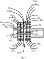
- FIG illustration 1 An exemplary distribution system according to the invention is shown in FIG illustration 1 shown.
- the distribution system has at least one electronic fuse terminal SK 1 .
- the invention is not limited thereto, but may - as for example from the Figure 3 can be seen - also be used with 2 or more electronic fuse terminals SK 2 .
- the exemplary distribution system according to the invention has at least one first terminal RK 1 .
- Terminal blocks are intended to provide potentials to a plurality of customers. Terminal blocks have juxtaposed bridging shafts (in bridging planes) which, for example, serve to distribute potentials between the terminal blocks. Some terminal blocks also have one or more terminals in one or more levels at which the respective potential provided by the bridge can be routed to the consumers.
- the electronic fuse terminal SK 1 and the at least one terminal RK 1 are arranged immediately adjacent to a mounting rail TS.
- the mounting rail may be a rail, such as a DIN rail or a G-rail, made of a suitable material.
- An example of such a mounting rail TS is the so-called DIN rail.
- the electronic fuse terminal SK 1 and the at least one first terminal RK 1 have at least one adjacent bridging shaft.
- FIG. 1 and 2 an example with two bridging shafts is shown, wherein the bridging shafts are arranged in bridging planes BE 1 and BE 2 .
- FIG. 3 an example with four bridging shafts in the bridging levels BE 1 to BE 4 is shown.
- the electronic fuse terminal SK 1 indirectly via a power supply terminal SV, which is also arranged on the mounting rail TS, supplied via a second bridging plug BS 2 with an input voltage IN.
- the input voltage IN is connected directly to the electronic fuse terminal SK 1 . That is, the proposed system according to the invention is extremely flexible and allows, for example, the connection of powerful energy sources via the power supply terminal SV. For example, the connection of the power supply terminal SV can provide a larger conductor cross-section than the electronic fuse terminal SK 1 .
- the electronic fuse terminal SK 1 provides at least a first output potential OUT S secured.
- the secured first output potential OUT S is passed on to the first terminal RK 1 by means of a first bridging plug BS 1 .
- the system it is also possible for the system to continue to connect a second output potential GND, IN to a second bypass shaft Which differs from the first output potential OUT S.
- a second output potential GND, IN to a second bypass shaft which differs from the first output potential OUT S.
- Figure 3 shown that the electronic fuse terminal SK 2 on the terminal RK 1 the (unsecured) input potential in the bridging plane BE2 passes, while in the bridging level BE3 a ground potential GND to the terminal RK2 and the secure output potential OUTs in the bridging level BE1 is passed. That is, with a corresponding configuration of BrückungsJchte different potentials - both secured and unsecured - be distributed.
- ground potential GND as shown in the figures, be supplied by means of a terminal of the electronic fuse terminal, it would alternatively or additionally possible to provide a ground potential by means of a metallic mounting rail TS, then when applying the electronic fuse terminal an electrical contact is made with the mounting rail, eg by means of metallic fasteners.
- system may further comprise at least a second terminal, wherein the second terminal also has at least one adjacent bridging shaft, and wherein the electronic fuse terminal SK 1 and the second terminal are arranged immediately adjacent to the mounting rail TS.
- bridging plugs it may be necessary to build parallel connections by means of several bridging plugs so as to be able to connect e.g. to be able to carry a certain current.
- the secured output potential OUT S is distributed both to the terminal blocks RK 5..7 on the left of the electronic fuse terminal SK 1 and to the terminal blocks RK 1..4 on the right of the electronic fuse terminal SK 1 .
- the electronic fuse terminal SK 1 provides a remote message FM.
- this remote message can also be used as summary telegram, as in Figure 3 shown to be used. This can eg be provided in larger circuits a remote message to a service technician, so that the affected circuit is faster to find.
- an acoustic and / or optical warning device may also be provided for the local error message, for example a (red) light-emitting diode or an acoustic signal generator in order to provide rapid detection of a faulty or overloaded electronic fuse terminal.
- an (additional) operational indication e.g. by means of a green LED.
- the electronic fuse terminal SK 1 has a width of less than 7 mm, in particular 6.2 mm and can be inserted in preferred grid mass of terminal clamping systems of the Applicant.
- a triggering current value be preset.
- this current value can also be selected during production and / or during installation. As a result, individual concerns can be addressed better and at the same time costs can be reduced, since now the current value can be set appropriately for each device or every situation.
- the maximum current of the secured output potential (OUT S ) is limited to a preset value (eg 6 A) or is switched off when reaching or exceeding a certain value directly or with a delay.
- the electronic fuse terminal SK 1 has a manual release of the backup function. This can be advantageous, for example, for protection during assembly or maintenance work.
Landscapes
- Engineering & Computer Science (AREA)
- Power Engineering (AREA)
- Automation & Control Theory (AREA)
- Microelectronics & Electronic Packaging (AREA)
- Emergency Management (AREA)
- General Physics & Mathematics (AREA)
- Physics & Mathematics (AREA)
- Business, Economics & Management (AREA)
- Fuses (AREA)
- Connections Arranged To Contact A Plurality Of Conductors (AREA)
- Power Sources (AREA)
- Details Of Connecting Devices For Male And Female Coupling (AREA)
- Connection Or Junction Boxes (AREA)
Abstract
Description
- Die Erfindung betrifft ein Verteilungssystem mit einer elektronischen Sicherungsklemme und zumindest einer ersten Reihenklemme.
- Aus dem Stand der Technik sind bereits elektronische Sicherungen bekannt.
- Für Tragschienenmontage sind unterschiedliche Systeme bekannt.
- Zum einen gibt es sogenannte 1-kanalige Lösungen, die ein Potential gesichert an einem Anschluss zur Verfügung stellen, zum anderen gibt es mehrkanalige Lösungen, die mehrere Potentiale gesichert an unterschiedlichen Anschlüssen zur Verfügung stellen.
- Allerdings sind diese Lösungen nicht geeignet in einem industriellen Umfeld für eine Mehrzahl von Verbrauchern ein gesichertes Potential oder mehrere gesicherte Potentiale raumsparend und kostengünstig im Aufbau zur Verfügung zu stellen.
- Der Erfindung liegt die Aufgabe zu Grunde, eine verbessertes und kostengünstiges Verteilungssystem mit einer elektronischen Sicherungsklemme zu schaffen, die einen oder mehrere Nachteile aus dem Stand der Technik vermeidet.
- Die Lösung der Aufgabe erfolgt erfindungsgemäß durch die Merkmale des unabhängigen Anspruchs. Vorteilhafte Ausgestaltungen der Erfindung sind in den Unteransprüchen angegeben.
- Nachfolgend wird die Erfindung unter Bezugnahme auf die anliegende Zeichnung anhand bevorzugter Ausführungsformen näher erläutert.
- Es zeigen
- Fig. 1
- eine erste Prinzip-Darstellung gemäß Ausführungsformen der Erfindung,
- Fig. 2
- eine zweite Prinzip-Darstellung gemäß Ausführungsformen der Erfindung. und
- Fig. 3
- eine dritte Prinzip-Darstellung gemäß Ausführungsformen der Erfindung.
- Nachfolgend wird die Erfindung eingehender unter Bezugnahme auf die Figur dargestellt werden. Dabei ist anzumerken, dass unterschiedliche Aspekte beschrieben werden, die jeweils einzeln oder in Kombination zum Einsatz kommen können. D.h. jeglicher Aspekt kann mit unterschiedlichen Ausführungsformen der Erfindung verwendet werden, soweit nicht explizit als reine Alternative dargestellt.
- Weiterhin wird nachfolgend der Einfachheit halber in aller Regel immer nur auf eine Entität Bezug genommen werden. Soweit nicht explizit vermerkt, kann die Erfindung aber auch jeweils mehrere der betroffenen Entitäten aufweisen. Insofern ist die Verwendung der Wörter "ein", "eine" und "eines" nur als Hinweis darauf zu verstehen, dass in einer einfachen Ausführungsform zumindest eine Entität verwendet wird.
- In der nachfolgenden Beschreibung wird Bezug auf die Abbildungen genommen. Dabei werden in aller Regel gleiche oder gleichartige Elemente mit gleichen oder gleichartigen Referenzzeichen bezeichnet werden.
- Ein beispielhaftes Verteilungssystem gemäß der Erfindung ist in
Abbildung 1 dargestellt. - Das Verteilungssystem weist mindestens eine elektronische Sicherungsklemme SK1 auf. Dabei ist die Erfindung aber nicht hierauf beschränkt, sondern kann - wie z.B. aus der
Abbildung 3 ersichtlich ist - auch mit 2 oder mehr elektronischen Sicherungsklemmen SK2 verwendet werden. - Weiterhin weist das beispielhafte Verteilungssystem gemäß der Erfindung zumindest eine erste Reihenklemme RK1 auf.
- Reihenklemmen sind dabei dazu vorgesehen Potentiale an eine Mehrzahl von Abnehmern zur Verfügung zu stellen. Reihenklemmen weisen dazu nebeneinanderliegende Brückungsschächte (in Brückungsebenen) auf, welche z.B. der Verteilung von Potentialen zwischen den Reihenklemmen dienen. Manche Reihenklemmen weisen auch ein oder mehrere Anschlüsse in einer oder mehreren Ebenen auf, an denen das jeweilige über die Brückung zur Verfügung gestellte Potential zu den Abnehmern geführt werden kann.
- Die elektronische Sicherungsklemme SK1 und die zumindest eine Reihenklemme RK1 sind unmittelbar benachbart auf einer Montageschiene TS angeordnet. Die Montageschiene kann dabei eine Profilschiene, beispielsweise eine Hutschiene oder eine G-Schiene, aus einem geeigneten Material sein. Ein Beispiel einer solchen Montageschiene TS ist die sogenannte DIN-Schiene.
- Die elektronische Sicherungsklemme SK1 und die zumindest eine erste Reihenklemme RK1 verfügen über zumindest je einen benachbarten Brückungsschacht. In der
Abbildung 1 und2 ist ein Beispiel mit zwei Brückungsschächten gezeigt, wobei die Brückungsschächte in Brückungsebenen BE1 und BE2 angeordnet sind. In derAbbildung 3 ist ein Beispiel mit vier Brückungsschächten in den Brückungsebenen BE1 bis BE4 gezeigt. - In der
Abbildung 1 wird die elektronische Sicherungsklemme SK1 mittelbar über eine Stromanschlussklemme SV, welche ebenfalls auf der Montageschiene TS angeordnet ist, über einen zweiten Brückungsstecker BS2 mit einer Eingangsspannung IN versorgt. - In
Abbildung 2 und3 wird hingegen die Eingangsspannung IN direkt an die elektronische Sicherungsklemme SK1 angeschlossen. D.h. das vorgestellte erfindungsgemäße System ist äußerst flexibel und erlaubt z.B. über die Stromanschlussklemme SV den Anschluss leistungsfähiger Energiequellen. Beispielsweise kann der Anschluss der Stromanschlussklemme SV einen größeren Leiter-Querschnitt als die elektronische Sicherungsklemme SK1 bieten. - Soweit im Folgenden Potentiale aufgezeigt werden, die eine Verwendung von Gleichspannung nahelegen, sei darauf hingewiesen, dass die Erfindung nicht hierauf beschränkt ist.
- Die elektronische Sicherungsklemme SK1 stellt zumindest ein erstes Ausgangspotential OUTS gesichert zur Verfügung.
- Dabei wird das gesicherte erste Ausgangspotential OUTS mittels eines ersten Brückungssteckers BS1 an die erste Reihenklemme RK1 weitergereicht.
- Gemäß einem Aspekt der Erfindung ist es zudem möglich, dass das System weiterhin an einem zweiten Brückungsschacht ein zweites Ausgangspotential GND, IN zur Verfügung stellt, das verschieden vom ersten Ausgangspotential OUTS ist. Beispielsweise ist in
Abbildung 3 gezeigt, dass die elektronische Sicherungsklemme SK2 an die Reihenklemme RK1 das (ungesicherte) Eingangspotential in der Brückungsebene BE2 weiterreicht, während in der Brückungsebene BE3 ein Erdpotential GND an die Reihenklemme RK2 und das gesicherte Ausgangspotential OUTs in der Brückungsebene BE1 weitergereicht wird. D.h. mit einer entsprechenden Ausgestaltung der Brückungsschächte können unterschiedliche Potentiale - sowohl gesicherte als auch ungesicherte - verteilt werden. - Zwar kann das Erdpotential GND, wie in den Abbildungen dargestellt, mittels eines Anschlusses der elektronischen Sicherungsklemme zugeführt sein, es wäre alternativ oder zusätzlich möglich ein Erdpotential auch mittels einer metallischen Montageschiene TS zur Verfügung zu stellen, wobei dann beim Aufbringen der elektronischen Sicherungsklemme ein elektrischer Kontakt mit der Montageschiene hergestellt wird, z.B. mittels metallischer Befestigungselemente.
- Natürlich kann das System weiterhin zumindest eine zweite Reihenklemme aufweisen, wobei die zweite Reihenklemme ebenfalls über zumindest einen benachbarten Brückungsschacht verfügt, und wobei die elektronische Sicherungsklemme SK1 und die zweite Reihenklemme unmittelbar benachbart auf der Montageschiene TS angeordnet sind.
- Dabei kann, wie in
Abbildung 2 gezeigt, das gesicherte erste Ausgangspotential OUTS an die zweite Reihenklemme RK5 mittels des ersten Brückungssteckers BS1 und/oder eines zweiten Brückungssteckers (nicht dargestellt) an die zweite Reihenklemme RK5 weitergereicht werden. - Beispielsweise kann es erforderlich sein, mittels mehrerer Brückungsstecker parallele Verbindungen aufzubauen, um so z.B. einen gewissen Strom tragen zu können.
- D.h. in
Abbildung 2 wird das gesicherte Ausganspotential OUTS sowohl an die Reihenklemmen RK5..7 links der elektronische Sicherungsklemme SK1 als auch an die Reihenklemmen RK1..4 rechts der elektronische Sicherungsklemme SK1 verteilt. - Andererseits ist es aber auch möglich, unterschiedliche (gesicherte und/oder ungesicherte) Potentiale nach rechts und nach links zu verteilen, wie aus einer Zusammenschau der Lehren der
Abbildung 2 und derAbbildung 3 unmittelbar einsichtig wird. - Besonders vorteilhaft kann zudem vorgesehen sein, dass die elektronische Sicherungsklemme SK1 eine Fernmeldung FM zur Verfügung stellt. Diese Fernmeldung kann zugleich aber auch z.B. als Summenfernmeldung, wie in
Abbildung 3 gezeigt, verwendet werden. Hiermit kann z.B. in größeren Schaltungen eine Fernmeldung an einen Servicetechniker bereitgestellt werden, sodass die betroffene Schaltung schneller auffindbar ist. - Alternativ oder zusätzlich kann zudem eine akustische und/oder optische Warneinrichtung zur lokalen Fehlermeldung zur Verfügung gestellt sein, beispielsweise eine (rote) Leuchtdiode oder einen akustischen Signalgeber, um eine schnelle Auffindung einer fehlerbehafteten oder überlasteten elektronischen Sicherungsklemme zur Verfügung zu stellen. Alternativ oder zusätzlich kann auch eine (zusätzliche) Betriebsanzeige, z.B. mittels einer grünen LED, ermöglicht werden.
- Von besonderem Vorteil ist, dass die elektronische Sicherungsklemme SK1 eine Breite von weniger als 7 mm, insbesondere 6,2 mm aufweist und so in bevorzugte Rastermasse von Reihenklemmsystemen der Anmelderin eingefügt werden kann.
- Weiterhin vorteilhaft kann bei der elektronischen Sicherungsklemme SK1 ein auslösender Stromwert fest voreingestellte sein. Dieser Stromwert kann aber auch in der Produktion und/oder beim Einbau wählbar sein. Hierdurch kann auf individuelle Belange besser eingegangen werden und zugleich Kosten reduziert werden, da nunmehr der Stromwert passend für jedes Gerät bzw. jede Situation eingestellt werden kann.
- Insbesondere kann vorgesehen sein, dass der maximale Strom des gesicherten Ausgangspotentials (OUTS) auf einen voreingestellten Wert begrenzt (z.B. 6 A) oder aber bei Erreichen oder Überschreiten eines bestimmten Wertes unmittelbar oder mit Verzögerung abgeschaltet wird.
- Zudem kann vorgesehen sein, dass die elektronische Sicherungsklemme SK1 eine manuelle Auslösung der Sicherungsfunktion aufweist. Dies kann z.B. zum Schutz bei Montage- oder Wartungsarbeiten vorteilhaft sein.
- D.h. mit der Erfindung ist es nunmehr möglich, eine größere Anzahl von Verbrauchern anzuschließen.
- Zudem ist es mit der Erfindung möglich, eine größere Anzahl von Verbrauchern bauraumsparend anzuschließen.
Bezugszeichenliste Reihenklemme RK1..N elektronische Sicherungsklemme SK1, SK2 Montageschiene TS Eingangsspannung IN erstes Ausgangspotential OUTS Brückungsstecker BS1, BS2 Fernmeldung FM Stromanschlussklemme SV Brückungsebene BE1..4
Claims (10)
- Verteilungssystem mit einer elektronischen Sicherungsklemme (SK1) und zumindest einer ersten Reihenklemme (RK1),• wobei die elektronische Sicherungsklemme (SK1) und die zumindest eine erste Reihenklemme (RK1) unmittelbar benachbart auf einer Montageschiene (TS) angeordnet sind, und wobei die elektronische Sicherungsklemme (SK1) und die zumindest eine erste Reihenklemme (RK1) über zumindest je einen benachbarten Brückungsschacht verfügen,• wobei die elektronische Sicherungsklemme (SK1) mit Eingangsspannung (IN) versorgbar ist, wobei die elektronische Sicherungsklemme (SK1) zumindest ein erstes Ausgangspotential (OUTS) gesichert zur Verfügung stellt,• wobei das gesicherte erste Ausgangspotential (OUTS) an die erste Reihenklemme (RK1) mittels eines ersten Brückungssteckers (BS1) an die erste Reihenklemme (RK1) weitergereicht wird.
- Verteilungssystem nach Anspruch 1, dadurch gekennzeichnet, dass das System weiterhin an einem zweiten Brückungsschacht ein zweites Ausgangspotential (GND, IN) zur Verfügung stellt, das verschieden vom ersten Ausgangspotential (OUTS) ist.
- Verteilungssystem nach Anspruch 1 oder 2, dadurch gekennzeichnet, dass das System weiterhin zumindest eine zweite Reihenklemme (RK2) aufweist, wobei die zweite Reihenklemme (RK2) über zumindest einen benachbarten Brückungsschacht verfügt, wobei die elektronische Sicherungsklemme (SK1) und die zweite Reihenklemme (RK1) unmittelbar benachbart auf einer Montageschiene (TS) angeordnet sind, wobei das gesicherte erste Ausgangspotential (OUTS) an die zweite Reihenklemme (RK2) mittels des ersten Brückungssteckers (BS1) oder eines zweiten Brückungssteckers (BS2) an die zweite Reihenklemme (RK2) weitergereicht wird.
- Verteilungssystem nach Anspruch 1 oder 2, dadurch gekennzeichnet, dass das System weiterhin zumindest eine zweite Reihenklemme aufweist, wobei die elektronische Sicherungsklemme (SK1) und die zweite Reihenklemme unmittelbar benachbart auf einer Montageschiene (TS) angeordnet sind, wobei die elektronische Sicherungsklemme (SK1) zumindest ein zweites Ausgangspotential gesichert zur Verfügung stellt, wobei das gesicherte zweite Ausgangspotential an die zweite Brückenklemme (SK1) mittels eines zweiten Brückungssteckers (BS2) an die zweite Reihenklemme weitergereicht wird.
- Verteilungssystem nach einem der vorhergehenden Ansprüche, dadurch gekennzeichnet, dass die elektronische Sicherungsklemme (SK1) eine Fernmeldung (FM) zur Verfügung stellt.
- Verteilungssystem nach einem der vorhergehenden Ansprüche, dadurch gekennzeichnet, dass die elektronische Sicherungsklemme (SK1) eine Warneinrichtung zur lokalen Fehlermeldung zur Verfügung stellt.
- Verteilungssystem nach einem der vorhergehenden Ansprüche, dadurch gekennzeichnet, dass die elektronische Sicherungsklemme (SK1) eine Breite von weniger als 7 mm, insbesondere 6,2 mm aufweist.
- Verteilungssystem nach einem der vorhergehenden Ansprüche, dadurch gekennzeichnet, dass die elektronische Sicherungsklemme (SK1) fest voreingestellten Stromwert aufweist.
- Verteilungssystem nach einem der vorhergehenden Ansprüche, dadurch gekennzeichnet, dass die elektronische Sicherungsklemme (SK1) den Strom des gesicherten Ausgangspotentials (OUTS) auf einen voreingestellten Wert begrenzt.
- Verteilungssystem nach einem der vorhergehenden Ansprüche, dadurch gekennzeichnet, dass die elektronischen Sicherungsklemme (SK1) eine manuelle Auslösung der Sicherungsfunktion aufweist.
Applications Claiming Priority (1)
| Application Number | Priority Date | Filing Date | Title |
|---|---|---|---|
| DE202015106368.7U DE202015106368U1 (de) | 2015-11-23 | 2015-11-23 | Verteilungssystem mit einer elektronischen Sicherungsklemme und zumindest einer ersten Reihenklemme |
Publications (2)
| Publication Number | Publication Date |
|---|---|
| EP3171682A1 true EP3171682A1 (de) | 2017-05-24 |
| EP3171682B1 EP3171682B1 (de) | 2020-09-23 |
Family
ID=57421640
Family Applications (1)
| Application Number | Title | Priority Date | Filing Date |
|---|---|---|---|
| EP16200128.3A Revoked EP3171682B1 (de) | 2015-11-23 | 2016-11-23 | Verteilungssystem mit einer elektronischen sicherungsklemme und zumindest einer ersten reihenklemme |
Country Status (7)
| Country | Link |
|---|---|
| US (1) | US10594134B2 (de) |
| EP (1) | EP3171682B1 (de) |
| JP (1) | JP6445508B2 (de) |
| KR (1) | KR20170059903A (de) |
| CN (1) | CN106816814A (de) |
| DE (1) | DE202015106368U1 (de) |
| RU (1) | RU2654540C1 (de) |
Families Citing this family (3)
| Publication number | Priority date | Publication date | Assignee | Title |
|---|---|---|---|---|
| CN110342434B (zh) * | 2019-08-16 | 2024-05-24 | 杭叉集团股份有限公司 | 一种叉车电气集成控制盒 |
| DE202022100382U1 (de) | 2022-01-24 | 2023-04-27 | WAGO Verwaltungsgesellschaft mit beschränkter Haftung | Reihenklemmensystem |
| BE1032911B1 (de) * | 2024-08-30 | 2026-04-15 | Phoenix Contact Gmbh & Co | Überspannungsschutzsystem mit Reihenklemmen auf einer Tragschiene |
Citations (2)
| Publication number | Priority date | Publication date | Assignee | Title |
|---|---|---|---|---|
| DE102004013477A1 (de) * | 2004-03-18 | 2005-10-06 | Epcos Ag | Trägerplattform für Leistungselektronik-Bauelemente und Modul mit der Trägerplattform |
| WO2015124800A1 (de) * | 2014-02-24 | 2015-08-27 | Weidmüller Interface GmbH & Co. KG | Anordnung zur stromverteilung in einem niederspannungssystem |
Family Cites Families (19)
| Publication number | Priority date | Publication date | Assignee | Title |
|---|---|---|---|---|
| US1526A (en) * | 1840-03-25 | Manner of fastening bedsteads and attaching and stretching sackings | ||
| SU748595A1 (ru) * | 1978-06-17 | 1980-07-15 | Предприятие П/Я А-3395 | Электрический соединитель |
| US4394639A (en) * | 1978-12-18 | 1983-07-19 | Mcgalliard James D | Printed circuit fuse assembly |
| DD142981B1 (de) * | 1979-05-11 | 1981-08-26 | Guenter Salewski | Anschlussleiste fuer kabelendverschluesse |
| JPH0766734B2 (ja) * | 1987-09-01 | 1995-07-19 | 矢崎総業株式会社 | ヒューズの製造方法 |
| DE4023237A1 (de) * | 1990-04-14 | 1991-10-17 | Sachsenwerk Ag | Schalteinrichtung mit einem lastschalter oder lasttrennschalter und einer sicherung |
| DE10024560A1 (de) | 2000-05-18 | 2001-11-22 | Bettermann Obo Gmbh & Co Kg | Überspannungsschutzgerät |
| RU18461U1 (ru) * | 2000-11-27 | 2001-06-20 | Общество с ограниченной ответственностью Научно-производственное предприятие "Комтранс" | Клеммная колодка |
| US6510047B2 (en) * | 2000-12-22 | 2003-01-21 | Eaton Corporation | Conductive heat sink |
| JP3958589B2 (ja) * | 2002-01-23 | 2007-08-15 | 株式会社オートネットワーク技術研究所 | 電気接続箱 |
| DE102004018554B4 (de) | 2004-04-14 | 2018-09-27 | Wago Verwaltungsgesellschaft Mbh | Brücker für elektrische Klemmen |
| US7561017B2 (en) * | 2004-09-13 | 2009-07-14 | Cooper Technologies Company | Fusible switching disconnect modules and devices |
| JP4527042B2 (ja) * | 2005-10-21 | 2010-08-18 | 矢崎総業株式会社 | 電気接続箱 |
| RU88855U1 (ru) * | 2009-06-18 | 2009-11-20 | Общество с ограниченной ответственностью "Русская электротехническая компания" ("РУСЭЛКОМ") | Клеммная колодка |
| CN201956741U (zh) * | 2011-01-13 | 2011-08-31 | 龙飞集团有限公司 | 电源分配器 |
| DE102014218646B4 (de) | 2013-09-18 | 2025-11-06 | Phoenix Contact Gmbh & Co. Kg | Steckbare aktive Elemente in Querrichtung für Reihenklemmensysteme mit Kodiersystem |
| DE102014105316A1 (de) | 2014-04-14 | 2015-10-15 | Weidmüller Interface GmbH & Co. KG | Reihenklemmenblock |
| DE102014213728A1 (de) | 2014-07-15 | 2016-01-21 | Phoenix Contact Gmbh & Co. Kg | Reihenklemmsystem |
| US10001526B2 (en) * | 2014-10-17 | 2018-06-19 | Eaton Intelligent Power Limited | Self-testing ground fault circuit interrupter |
-
2015
- 2015-11-23 DE DE202015106368.7U patent/DE202015106368U1/de not_active Expired - Lifetime
-
2016
- 2016-11-14 JP JP2016221966A patent/JP6445508B2/ja not_active Expired - Fee Related
- 2016-11-18 RU RU2016145300A patent/RU2654540C1/ru active
- 2016-11-22 US US15/359,230 patent/US10594134B2/en not_active Expired - Fee Related
- 2016-11-22 KR KR1020160156051A patent/KR20170059903A/ko not_active Ceased
- 2016-11-23 EP EP16200128.3A patent/EP3171682B1/de not_active Revoked
- 2016-11-23 CN CN201611037156.2A patent/CN106816814A/zh active Pending
Patent Citations (2)
| Publication number | Priority date | Publication date | Assignee | Title |
|---|---|---|---|---|
| DE102004013477A1 (de) * | 2004-03-18 | 2005-10-06 | Epcos Ag | Trägerplattform für Leistungselektronik-Bauelemente und Modul mit der Trägerplattform |
| WO2015124800A1 (de) * | 2014-02-24 | 2015-08-27 | Weidmüller Interface GmbH & Co. KG | Anordnung zur stromverteilung in einem niederspannungssystem |
Also Published As
| Publication number | Publication date |
|---|---|
| CN106816814A (zh) | 2017-06-09 |
| JP6445508B2 (ja) | 2018-12-26 |
| JP2017162441A (ja) | 2017-09-14 |
| EP3171682B1 (de) | 2020-09-23 |
| KR20170059903A (ko) | 2017-05-31 |
| RU2654540C1 (ru) | 2018-05-21 |
| RU2016145300A3 (de) | 2018-05-21 |
| DE202015106368U1 (de) | 2017-02-24 |
| US20170149239A1 (en) | 2017-05-25 |
| RU2016145300A (ru) | 2018-05-21 |
| US10594134B2 (en) | 2020-03-17 |
Similar Documents
| Publication | Publication Date | Title |
|---|---|---|
| EP3218230A1 (de) | Kraftfahrzeug-versorgungsnetz | |
| DE102016209445A1 (de) | Störlichtbogenerkennungseinheit | |
| WO2016008919A1 (de) | Reihenklemmsystem | |
| EP3171682B1 (de) | Verteilungssystem mit einer elektronischen sicherungsklemme und zumindest einer ersten reihenklemme | |
| DE102017111245A1 (de) | Stromverteiler | |
| DE102014225431A1 (de) | Vorrichtung und Verfahren zum Trennen und Verbinden zweier Teilbordnetze | |
| DE102012100673A1 (de) | Vorrichtung zur elektrischen Energieeinspeisung aus einer dezentralen Eigenerzeugeranlage in ein Stromnetz | |
| DE102017011374A1 (de) | Schutzeinrichtung für Niederspannungsanlagen mit integrierter Messelektronik | |
| DE102017211121A1 (de) | Brandschutzschalter und Verfahren | |
| EP2992571A1 (de) | Busanschlussvorrichtung | |
| DE102008016388B4 (de) | Vorrichtung zum Testen einer Schutz-, Mess- oder Zähleinrichtung als Bestandteil einer Mittel- oder Hochspannungsanlage | |
| DE102012210292A1 (de) | Schmelzsicherungsanordnung | |
| BE1026349A1 (de) | Schutzschalter mit Überwachungseinrichtung und Verfahren hierfür | |
| EP1364459A2 (de) | Sicherheitsschaltvorrichtung | |
| DE102015211625A1 (de) | Reversible elektronische Schutzschalterklemme | |
| DE102014003910A1 (de) | Anschlussnetzwerk, Prüfvorrichtung und Verfahren zum gleichzeitigen Prüfen mehrerer Batteriezellen | |
| DE102012201514A1 (de) | Schütz | |
| EP3111516B1 (de) | Anordnung zur stromverteilung in einem niederspannungssystem | |
| DE102015223055A1 (de) | Verteilungssystem mit einer elektronischen Sicherungsklemme und zumindest einer ersten Reihenklemme | |
| DE102023116929A1 (de) | Elektrisches Überspannungsschutzgerät | |
| DE102012016133A1 (de) | Elektrisches Verbindungssystem insbesondere für Schaltschränke | |
| LU101568B1 (de) | Schnittstellenanordnung zum Verbinden wenigstens einer Steuerungseinrichtung mit mehreren Feldgeräten | |
| AT397439B (de) | Schaltung zur überwachung der isolationswiderstände einer schar von baugruppen einer elektrischen anlage mit gemeinsamer erdfreier stromversorgung, insbesondere einer fernmelde- oder signaltechnischen einrichtung | |
| DE102018206269A1 (de) | Gleichspannungswandler, Bordnetz mit einem Gleichspannungswandler | |
| LU505197B1 (de) | Elektrische Messvorrichtung für Reihenklemmen |
Legal Events
| Date | Code | Title | Description |
|---|---|---|---|
| PUAI | Public reference made under article 153(3) epc to a published international application that has entered the european phase |
Free format text: ORIGINAL CODE: 0009012 |
|
| STAA | Information on the status of an ep patent application or granted ep patent |
Free format text: STATUS: THE APPLICATION HAS BEEN PUBLISHED |
|
| AK | Designated contracting states |
Kind code of ref document: A1 Designated state(s): AL AT BE BG CH CY CZ DE DK EE ES FI FR GB GR HR HU IE IS IT LI LT LU LV MC MK MT NL NO PL PT RO RS SE SI SK SM TR |
|
| AX | Request for extension of the european patent |
Extension state: BA ME |
|
| STAA | Information on the status of an ep patent application or granted ep patent |
Free format text: STATUS: REQUEST FOR EXAMINATION WAS MADE |
|
| 17P | Request for examination filed |
Effective date: 20171124 |
|
| RBV | Designated contracting states (corrected) |
Designated state(s): AL AT BE BG CH CY CZ DE DK EE ES FI FR GB GR HR HU IE IS IT LI LT LU LV MC MK MT NL NO PL PT RO RS SE SI SK SM TR |
|
| REG | Reference to a national code |
Ref country code: DE Ref legal event code: R079 Ref document number: 502016011234 Country of ref document: DE Free format text: PREVIOUS MAIN CLASS: H05K0005000000 Ipc: H05K0007140000 |
|
| GRAP | Despatch of communication of intention to grant a patent |
Free format text: ORIGINAL CODE: EPIDOSNIGR1 |
|
| RIC1 | Information provided on ipc code assigned before grant |
Ipc: H02B 1/00 20060101ALI20200623BHEP Ipc: H05K 7/14 20060101AFI20200623BHEP |
|
| STAA | Information on the status of an ep patent application or granted ep patent |
Free format text: STATUS: GRANT OF PATENT IS INTENDED |
|
| GRAS | Grant fee paid |
Free format text: ORIGINAL CODE: EPIDOSNIGR3 |
|
| GRAA | (expected) grant |
Free format text: ORIGINAL CODE: 0009210 |
|
| STAA | Information on the status of an ep patent application or granted ep patent |
Free format text: STATUS: THE PATENT HAS BEEN GRANTED |
|
| INTG | Intention to grant announced |
Effective date: 20200730 |
|
| RIN1 | Information on inventor provided before grant (corrected) |
Inventor name: NAHLES, GUIDO Inventor name: BERG, PETER Inventor name: BESSLER TIMO Inventor name: FOMENKO, ALEXANDER Inventor name: WETTER, MARTIN Inventor name: PLATTMANN CARSTEN Inventor name: JUERGENHAKE CHRISTIAN Inventor name: KETLER PETER |
|
| AK | Designated contracting states |
Kind code of ref document: B1 Designated state(s): AL AT BE BG CH CY CZ DE DK EE ES FI FR GB GR HR HU IE IS IT LI LT LU LV MC MK MT NL NO PL PT RO RS SE SI SK SM TR |
|
| REG | Reference to a national code |
Ref country code: GB Ref legal event code: FG4D Free format text: NOT ENGLISH |
|
| RIN1 | Information on inventor provided before grant (corrected) |
Inventor name: BERG, PETER Inventor name: WETTER, MARTIN Inventor name: KETLER PETER Inventor name: PLATTMANN CARSTEN Inventor name: NAHLES, GUIDO Inventor name: JUERGENHAKE CHRISTIAN Inventor name: BESSLER TIMO Inventor name: FOMENKO, ALEXANDER |
|
| REG | Reference to a national code |
Ref country code: CH Ref legal event code: EP |
|
| REG | Reference to a national code |
Ref country code: DE Ref legal event code: R096 Ref document number: 502016011234 Country of ref document: DE |
|
| REG | Reference to a national code |
Ref country code: IE Ref legal event code: FG4D Free format text: LANGUAGE OF EP DOCUMENT: GERMAN |
|
| REG | Reference to a national code |
Ref country code: AT Ref legal event code: REF Ref document number: 1317770 Country of ref document: AT Kind code of ref document: T Effective date: 20201015 |
|
| PG25 | Lapsed in a contracting state [announced via postgrant information from national office to epo] |
Ref country code: FI Free format text: LAPSE BECAUSE OF FAILURE TO SUBMIT A TRANSLATION OF THE DESCRIPTION OR TO PAY THE FEE WITHIN THE PRESCRIBED TIME-LIMIT Effective date: 20200923 Ref country code: HR Free format text: LAPSE BECAUSE OF FAILURE TO SUBMIT A TRANSLATION OF THE DESCRIPTION OR TO PAY THE FEE WITHIN THE PRESCRIBED TIME-LIMIT Effective date: 20200923 Ref country code: BG Free format text: LAPSE BECAUSE OF FAILURE TO SUBMIT A TRANSLATION OF THE DESCRIPTION OR TO PAY THE FEE WITHIN THE PRESCRIBED TIME-LIMIT Effective date: 20201223 Ref country code: GR Free format text: LAPSE BECAUSE OF FAILURE TO SUBMIT A TRANSLATION OF THE DESCRIPTION OR TO PAY THE FEE WITHIN THE PRESCRIBED TIME-LIMIT Effective date: 20201224 Ref country code: NO Free format text: LAPSE BECAUSE OF FAILURE TO SUBMIT A TRANSLATION OF THE DESCRIPTION OR TO PAY THE FEE WITHIN THE PRESCRIBED TIME-LIMIT Effective date: 20201223 Ref country code: SE Free format text: LAPSE BECAUSE OF FAILURE TO SUBMIT A TRANSLATION OF THE DESCRIPTION OR TO PAY THE FEE WITHIN THE PRESCRIBED TIME-LIMIT Effective date: 20200923 |
|
| PG25 | Lapsed in a contracting state [announced via postgrant information from national office to epo] |
Ref country code: LV Free format text: LAPSE BECAUSE OF FAILURE TO SUBMIT A TRANSLATION OF THE DESCRIPTION OR TO PAY THE FEE WITHIN THE PRESCRIBED TIME-LIMIT Effective date: 20200923 Ref country code: RS Free format text: LAPSE BECAUSE OF FAILURE TO SUBMIT A TRANSLATION OF THE DESCRIPTION OR TO PAY THE FEE WITHIN THE PRESCRIBED TIME-LIMIT Effective date: 20200923 |
|
| REG | Reference to a national code |
Ref country code: NL Ref legal event code: MP Effective date: 20200923 |
|
| REG | Reference to a national code |
Ref country code: LT Ref legal event code: MG4D |
|
| PG25 | Lapsed in a contracting state [announced via postgrant information from national office to epo] |
Ref country code: CZ Free format text: LAPSE BECAUSE OF FAILURE TO SUBMIT A TRANSLATION OF THE DESCRIPTION OR TO PAY THE FEE WITHIN THE PRESCRIBED TIME-LIMIT Effective date: 20200923 Ref country code: SM Free format text: LAPSE BECAUSE OF FAILURE TO SUBMIT A TRANSLATION OF THE DESCRIPTION OR TO PAY THE FEE WITHIN THE PRESCRIBED TIME-LIMIT Effective date: 20200923 Ref country code: PT Free format text: LAPSE BECAUSE OF FAILURE TO SUBMIT A TRANSLATION OF THE DESCRIPTION OR TO PAY THE FEE WITHIN THE PRESCRIBED TIME-LIMIT Effective date: 20210125 Ref country code: RO Free format text: LAPSE BECAUSE OF FAILURE TO SUBMIT A TRANSLATION OF THE DESCRIPTION OR TO PAY THE FEE WITHIN THE PRESCRIBED TIME-LIMIT Effective date: 20200923 Ref country code: LT Free format text: LAPSE BECAUSE OF FAILURE TO SUBMIT A TRANSLATION OF THE DESCRIPTION OR TO PAY THE FEE WITHIN THE PRESCRIBED TIME-LIMIT Effective date: 20200923 Ref country code: EE Free format text: LAPSE BECAUSE OF FAILURE TO SUBMIT A TRANSLATION OF THE DESCRIPTION OR TO PAY THE FEE WITHIN THE PRESCRIBED TIME-LIMIT Effective date: 20200923 |
|
| PG25 | Lapsed in a contracting state [announced via postgrant information from national office to epo] |
Ref country code: ES Free format text: LAPSE BECAUSE OF FAILURE TO SUBMIT A TRANSLATION OF THE DESCRIPTION OR TO PAY THE FEE WITHIN THE PRESCRIBED TIME-LIMIT Effective date: 20200923 Ref country code: AL Free format text: LAPSE BECAUSE OF FAILURE TO SUBMIT A TRANSLATION OF THE DESCRIPTION OR TO PAY THE FEE WITHIN THE PRESCRIBED TIME-LIMIT Effective date: 20200923 Ref country code: PL Free format text: LAPSE BECAUSE OF FAILURE TO SUBMIT A TRANSLATION OF THE DESCRIPTION OR TO PAY THE FEE WITHIN THE PRESCRIBED TIME-LIMIT Effective date: 20200923 Ref country code: IS Free format text: LAPSE BECAUSE OF FAILURE TO SUBMIT A TRANSLATION OF THE DESCRIPTION OR TO PAY THE FEE WITHIN THE PRESCRIBED TIME-LIMIT Effective date: 20210123 |
|
| REG | Reference to a national code |
Ref country code: DE Ref legal event code: R026 Ref document number: 502016011234 Country of ref document: DE |
|
| PLBI | Opposition filed |
Free format text: ORIGINAL CODE: 0009260 |
|
| PG25 | Lapsed in a contracting state [announced via postgrant information from national office to epo] |
Ref country code: SK Free format text: LAPSE BECAUSE OF FAILURE TO SUBMIT A TRANSLATION OF THE DESCRIPTION OR TO PAY THE FEE WITHIN THE PRESCRIBED TIME-LIMIT Effective date: 20200923 Ref country code: MC Free format text: LAPSE BECAUSE OF FAILURE TO SUBMIT A TRANSLATION OF THE DESCRIPTION OR TO PAY THE FEE WITHIN THE PRESCRIBED TIME-LIMIT Effective date: 20200923 |
|
| REG | Reference to a national code |
Ref country code: CH Ref legal event code: PL |
|
| PLAX | Notice of opposition and request to file observation + time limit sent |
Free format text: ORIGINAL CODE: EPIDOSNOBS2 |
|
| 26 | Opposition filed |
Opponent name: WAGO KONTAKTTECHNIK GMBH & CO. KG Effective date: 20210623 |
|
| PG25 | Lapsed in a contracting state [announced via postgrant information from national office to epo] |
Ref country code: LU Free format text: LAPSE BECAUSE OF NON-PAYMENT OF DUE FEES Effective date: 20201123 |
|
| REG | Reference to a national code |
Ref country code: BE Ref legal event code: MM Effective date: 20201130 |
|
| GBPC | Gb: european patent ceased through non-payment of renewal fee |
Effective date: 20201223 |
|
| PG25 | Lapsed in a contracting state [announced via postgrant information from national office to epo] |
Ref country code: LI Free format text: LAPSE BECAUSE OF NON-PAYMENT OF DUE FEES Effective date: 20201130 Ref country code: SI Free format text: LAPSE BECAUSE OF FAILURE TO SUBMIT A TRANSLATION OF THE DESCRIPTION OR TO PAY THE FEE WITHIN THE PRESCRIBED TIME-LIMIT Effective date: 20200923 Ref country code: CH Free format text: LAPSE BECAUSE OF NON-PAYMENT OF DUE FEES Effective date: 20201130 Ref country code: DK Free format text: LAPSE BECAUSE OF FAILURE TO SUBMIT A TRANSLATION OF THE DESCRIPTION OR TO PAY THE FEE WITHIN THE PRESCRIBED TIME-LIMIT Effective date: 20200923 |
|
| PG25 | Lapsed in a contracting state [announced via postgrant information from national office to epo] |
Ref country code: FR Free format text: LAPSE BECAUSE OF NON-PAYMENT OF DUE FEES Effective date: 20201123 Ref country code: IT Free format text: LAPSE BECAUSE OF FAILURE TO SUBMIT A TRANSLATION OF THE DESCRIPTION OR TO PAY THE FEE WITHIN THE PRESCRIBED TIME-LIMIT Effective date: 20200923 Ref country code: IE Free format text: LAPSE BECAUSE OF NON-PAYMENT OF DUE FEES Effective date: 20201123 |
|
| PLBB | Reply of patent proprietor to notice(s) of opposition received |
Free format text: ORIGINAL CODE: EPIDOSNOBS3 |
|
| PG25 | Lapsed in a contracting state [announced via postgrant information from national office to epo] |
Ref country code: GB Free format text: LAPSE BECAUSE OF NON-PAYMENT OF DUE FEES Effective date: 20201223 |
|
| PG25 | Lapsed in a contracting state [announced via postgrant information from national office to epo] |
Ref country code: IS Free format text: LAPSE BECAUSE OF FAILURE TO SUBMIT A TRANSLATION OF THE DESCRIPTION OR TO PAY THE FEE WITHIN THE PRESCRIBED TIME-LIMIT Effective date: 20210123 Ref country code: TR Free format text: LAPSE BECAUSE OF FAILURE TO SUBMIT A TRANSLATION OF THE DESCRIPTION OR TO PAY THE FEE WITHIN THE PRESCRIBED TIME-LIMIT Effective date: 20200923 Ref country code: MT Free format text: LAPSE BECAUSE OF FAILURE TO SUBMIT A TRANSLATION OF THE DESCRIPTION OR TO PAY THE FEE WITHIN THE PRESCRIBED TIME-LIMIT Effective date: 20200923 Ref country code: CY Free format text: LAPSE BECAUSE OF FAILURE TO SUBMIT A TRANSLATION OF THE DESCRIPTION OR TO PAY THE FEE WITHIN THE PRESCRIBED TIME-LIMIT Effective date: 20200923 |
|
| PG25 | Lapsed in a contracting state [announced via postgrant information from national office to epo] |
Ref country code: MK Free format text: LAPSE BECAUSE OF FAILURE TO SUBMIT A TRANSLATION OF THE DESCRIPTION OR TO PAY THE FEE WITHIN THE PRESCRIBED TIME-LIMIT Effective date: 20200923 |
|
| PLAB | Opposition data, opponent's data or that of the opponent's representative modified |
Free format text: ORIGINAL CODE: 0009299OPPO |
|
| PG25 | Lapsed in a contracting state [announced via postgrant information from national office to epo] |
Ref country code: BE Free format text: LAPSE BECAUSE OF NON-PAYMENT OF DUE FEES Effective date: 20201130 |
|
| R26 | Opposition filed (corrected) |
Opponent name: WAGO GMBH & CO. KG Effective date: 20210623 |
|
| RDAF | Communication despatched that patent is revoked |
Free format text: ORIGINAL CODE: EPIDOSNREV1 |
|
| REG | Reference to a national code |
Ref country code: AT Ref legal event code: MM01 Ref document number: 1317770 Country of ref document: AT Kind code of ref document: T Effective date: 20211123 |
|
| PG25 | Lapsed in a contracting state [announced via postgrant information from national office to epo] |
Ref country code: AT Free format text: LAPSE BECAUSE OF NON-PAYMENT OF DUE FEES Effective date: 20211123 |
|
| APBM | Appeal reference recorded |
Free format text: ORIGINAL CODE: EPIDOSNREFNO |
|
| APBP | Date of receipt of notice of appeal recorded |
Free format text: ORIGINAL CODE: EPIDOSNNOA2O |
|
| APAH | Appeal reference modified |
Free format text: ORIGINAL CODE: EPIDOSCREFNO |
|
| APBQ | Date of receipt of statement of grounds of appeal recorded |
Free format text: ORIGINAL CODE: EPIDOSNNOA3O |
|
| P01 | Opt-out of the competence of the unified patent court (upc) registered |
Effective date: 20230424 |
|
| PG25 | Lapsed in a contracting state [announced via postgrant information from national office to epo] |
Ref country code: NL Free format text: LAPSE BECAUSE OF NON-PAYMENT OF DUE FEES Effective date: 20200923 |
|
| PGFP | Annual fee paid to national office [announced via postgrant information from national office to epo] |
Ref country code: DE Payment date: 20250129 Year of fee payment: 9 |
|
| REG | Reference to a national code |
Ref country code: DE Ref legal event code: R103 Ref document number: 502016011234 Country of ref document: DE Ref country code: DE Ref legal event code: R064 Ref document number: 502016011234 Country of ref document: DE |
|
| APBU | Appeal procedure closed |
Free format text: ORIGINAL CODE: EPIDOSNNOA9O |
|
| RDAG | Patent revoked |
Free format text: ORIGINAL CODE: 0009271 |
|
| STAA | Information on the status of an ep patent application or granted ep patent |
Free format text: STATUS: PATENT REVOKED |
|
| REG | Reference to a national code |
Ref country code: CH Ref legal event code: PL |
|
| 27W | Patent revoked |
Effective date: 20250411 |
|
| REG | Reference to a national code |
Ref country code: AT Ref legal event code: MA03 Ref document number: 1317770 Country of ref document: AT Kind code of ref document: T Effective date: 20250326 |