EP3171232A1 - Atomic oscillator - Google Patents
Atomic oscillator Download PDFInfo
- Publication number
- EP3171232A1 EP3171232A1 EP16195500.0A EP16195500A EP3171232A1 EP 3171232 A1 EP3171232 A1 EP 3171232A1 EP 16195500 A EP16195500 A EP 16195500A EP 3171232 A1 EP3171232 A1 EP 3171232A1
- Authority
- EP
- European Patent Office
- Prior art keywords
- layer
- light
- light source
- atomic oscillator
- electrical field
- Prior art date
- Legal status (The legal status is an assumption and is not a legal conclusion. Google has not performed a legal analysis and makes no representation as to the accuracy of the status listed.)
- Granted
Links
- 238000010521 absorption reaction Methods 0.000 claims abstract description 72
- 230000003287 optical effect Effects 0.000 claims abstract description 62
- 238000009792 diffusion process Methods 0.000 claims abstract description 48
- 230000005684 electric field Effects 0.000 claims abstract description 47
- 239000004065 semiconductor Substances 0.000 claims abstract description 44
- 230000010355 oscillation Effects 0.000 claims abstract description 24
- 150000001340 alkali metals Chemical group 0.000 claims abstract description 23
- 229910001218 Gallium arsenide Inorganic materials 0.000 claims description 10
- 238000000034 method Methods 0.000 description 28
- 238000001514 detection method Methods 0.000 description 18
- 230000004048 modification Effects 0.000 description 15
- 238000012986 modification Methods 0.000 description 15
- 230000008569 process Effects 0.000 description 15
- 239000007789 gas Substances 0.000 description 12
- 239000000463 material Substances 0.000 description 10
- 239000000758 substrate Substances 0.000 description 10
- 230000008859 change Effects 0.000 description 8
- 238000004519 manufacturing process Methods 0.000 description 6
- 238000000059 patterning Methods 0.000 description 6
- TVFDJXOCXUVLDH-UHFFFAOYSA-N caesium atom Chemical group [Cs] TVFDJXOCXUVLDH-UHFFFAOYSA-N 0.000 description 4
- 238000005229 chemical vapour deposition Methods 0.000 description 4
- 230000001427 coherent effect Effects 0.000 description 4
- 238000010586 diagram Methods 0.000 description 4
- 230000000694 effects Effects 0.000 description 4
- 230000005284 excitation Effects 0.000 description 4
- 230000001590 oxidative effect Effects 0.000 description 4
- 239000004642 Polyimide Substances 0.000 description 3
- 238000005530 etching Methods 0.000 description 3
- 230000006870 function Effects 0.000 description 3
- 238000000206 photolithography Methods 0.000 description 3
- 229920001721 polyimide Polymers 0.000 description 3
- 238000004528 spin coating Methods 0.000 description 3
- KRHYYFGTRYWZRS-UHFFFAOYSA-N Fluorane Chemical compound F KRHYYFGTRYWZRS-UHFFFAOYSA-N 0.000 description 2
- 230000004888 barrier function Effects 0.000 description 2
- 230000015572 biosynthetic process Effects 0.000 description 2
- 239000000470 constituent Substances 0.000 description 2
- 238000005520 cutting process Methods 0.000 description 2
- 238000009826 distribution Methods 0.000 description 2
- 238000003475 lamination Methods 0.000 description 2
- 230000007774 longterm Effects 0.000 description 2
- IGLNJRXAVVLDKE-UHFFFAOYSA-N rubidium atom Chemical compound [Rb] IGLNJRXAVVLDKE-UHFFFAOYSA-N 0.000 description 2
- 238000001228 spectrum Methods 0.000 description 2
- 229910002704 AlGaN Inorganic materials 0.000 description 1
- 229910000980 Aluminium gallium arsenide Inorganic materials 0.000 description 1
- 229910016909 AlxOy Inorganic materials 0.000 description 1
- 229910000530 Gallium indium arsenide Inorganic materials 0.000 description 1
- VYPSYNLAJGMNEJ-UHFFFAOYSA-N Silicium dioxide Chemical compound O=[Si]=O VYPSYNLAJGMNEJ-UHFFFAOYSA-N 0.000 description 1
- 229910052783 alkali metal Inorganic materials 0.000 description 1
- PNEYBMLMFCGWSK-UHFFFAOYSA-N aluminium oxide Inorganic materials [O-2].[O-2].[O-2].[Al+3].[Al+3] PNEYBMLMFCGWSK-UHFFFAOYSA-N 0.000 description 1
- 125000004429 atom Chemical group 0.000 description 1
- 239000002585 base Substances 0.000 description 1
- 230000008901 benefit Effects 0.000 description 1
- 229910052792 caesium Inorganic materials 0.000 description 1
- 238000004891 communication Methods 0.000 description 1
- 229910052593 corundum Inorganic materials 0.000 description 1
- 238000010168 coupling process Methods 0.000 description 1
- 238000005859 coupling reaction Methods 0.000 description 1
- 238000011161 development Methods 0.000 description 1
- 229910000040 hydrogen fluoride Inorganic materials 0.000 description 1
- 230000003993 interaction Effects 0.000 description 1
- 230000031700 light absorption Effects 0.000 description 1
- 229910052751 metal Inorganic materials 0.000 description 1
- 239000002184 metal Substances 0.000 description 1
- 238000001451 molecular beam epitaxy Methods 0.000 description 1
- TWNQGVIAIRXVLR-UHFFFAOYSA-N oxo(oxoalumanyloxy)alumane Chemical compound O=[Al]O[Al]=O TWNQGVIAIRXVLR-UHFFFAOYSA-N 0.000 description 1
- 238000012545 processing Methods 0.000 description 1
- 230000005701 quantum confined stark effect Effects 0.000 description 1
- 229910052701 rubidium Inorganic materials 0.000 description 1
- 230000035939 shock Effects 0.000 description 1
- 229910052814 silicon oxide Inorganic materials 0.000 description 1
- 125000004436 sodium atom Chemical group 0.000 description 1
- 238000003860 storage Methods 0.000 description 1
- 230000007704 transition Effects 0.000 description 1
- 238000007740 vapor deposition Methods 0.000 description 1
- 229910001845 yogo sapphire Inorganic materials 0.000 description 1
Images


Classifications
-
- H—ELECTRICITY
- H03—ELECTRONIC CIRCUITRY
- H03L—AUTOMATIC CONTROL, STARTING, SYNCHRONISATION, OR STABILISATION OF GENERATORS OF ELECTRONIC OSCILLATIONS OR PULSES
- H03L7/00—Automatic control of frequency or phase; Synchronisation
- H03L7/26—Automatic control of frequency or phase; Synchronisation using energy levels of molecules, atoms, or subatomic particles as a frequency reference
-
- G—PHYSICS
- G04—HOROLOGY
- G04F—TIME-INTERVAL MEASURING
- G04F5/00—Apparatus for producing preselected time intervals for use as timing standards
- G04F5/14—Apparatus for producing preselected time intervals for use as timing standards using atomic clocks
- G04F5/145—Apparatus for producing preselected time intervals for use as timing standards using atomic clocks using Coherent Population Trapping
-
- H—ELECTRICITY
- H01—ELECTRIC ELEMENTS
- H01L—SEMICONDUCTOR DEVICES NOT COVERED BY CLASS H10
- H01L31/00—Semiconductor devices sensitive to infrared radiation, light, electromagnetic radiation of shorter wavelength or corpuscular radiation and specially adapted either for the conversion of the energy of such radiation into electrical energy or for the control of electrical energy by such radiation; Processes or apparatus specially adapted for the manufacture or treatment thereof or of parts thereof; Details thereof
- H01L31/12—Semiconductor devices sensitive to infrared radiation, light, electromagnetic radiation of shorter wavelength or corpuscular radiation and specially adapted either for the conversion of the energy of such radiation into electrical energy or for the control of electrical energy by such radiation; Processes or apparatus specially adapted for the manufacture or treatment thereof or of parts thereof; Details thereof structurally associated with, e.g. formed in or on a common substrate with, one or more electric light sources, e.g. electroluminescent light sources, and electrically or optically coupled thereto
- H01L31/16—Semiconductor devices sensitive to infrared radiation, light, electromagnetic radiation of shorter wavelength or corpuscular radiation and specially adapted either for the conversion of the energy of such radiation into electrical energy or for the control of electrical energy by such radiation; Processes or apparatus specially adapted for the manufacture or treatment thereof or of parts thereof; Details thereof structurally associated with, e.g. formed in or on a common substrate with, one or more electric light sources, e.g. electroluminescent light sources, and electrically or optically coupled thereto the semiconductor device sensitive to radiation being controlled by the light source or sources
-
- H—ELECTRICITY
- H01—ELECTRIC ELEMENTS
- H01L—SEMICONDUCTOR DEVICES NOT COVERED BY CLASS H10
- H01L33/00—Semiconductor devices with at least one potential-jump barrier or surface barrier specially adapted for light emission; Processes or apparatus specially adapted for the manufacture or treatment thereof or of parts thereof; Details thereof
- H01L33/36—Semiconductor devices with at least one potential-jump barrier or surface barrier specially adapted for light emission; Processes or apparatus specially adapted for the manufacture or treatment thereof or of parts thereof; Details thereof characterised by the electrodes
- H01L33/40—Materials therefor
-
- H—ELECTRICITY
- H01—ELECTRIC ELEMENTS
- H01L—SEMICONDUCTOR DEVICES NOT COVERED BY CLASS H10
- H01L33/00—Semiconductor devices with at least one potential-jump barrier or surface barrier specially adapted for light emission; Processes or apparatus specially adapted for the manufacture or treatment thereof or of parts thereof; Details thereof
- H01L33/48—Semiconductor devices with at least one potential-jump barrier or surface barrier specially adapted for light emission; Processes or apparatus specially adapted for the manufacture or treatment thereof or of parts thereof; Details thereof characterised by the semiconductor body packages
- H01L33/58—Optical field-shaping elements
- H01L33/60—Reflective elements
-
- H—ELECTRICITY
- H01—ELECTRIC ELEMENTS
- H01L—SEMICONDUCTOR DEVICES NOT COVERED BY CLASS H10
- H01L33/00—Semiconductor devices with at least one potential-jump barrier or surface barrier specially adapted for light emission; Processes or apparatus specially adapted for the manufacture or treatment thereof or of parts thereof; Details thereof
- H01L33/48—Semiconductor devices with at least one potential-jump barrier or surface barrier specially adapted for light emission; Processes or apparatus specially adapted for the manufacture or treatment thereof or of parts thereof; Details thereof characterised by the semiconductor body packages
- H01L33/64—Heat extraction or cooling elements
-
- H—ELECTRICITY
- H01—ELECTRIC ELEMENTS
- H01S—DEVICES USING THE PROCESS OF LIGHT AMPLIFICATION BY STIMULATED EMISSION OF RADIATION [LASER] TO AMPLIFY OR GENERATE LIGHT; DEVICES USING STIMULATED EMISSION OF ELECTROMAGNETIC RADIATION IN WAVE RANGES OTHER THAN OPTICAL
- H01S5/00—Semiconductor lasers
- H01S5/04—Processes or apparatus for excitation, e.g. pumping, e.g. by electron beams
- H01S5/042—Electrical excitation ; Circuits therefor
- H01S5/0425—Electrodes, e.g. characterised by the structure
- H01S5/04252—Electrodes, e.g. characterised by the structure characterised by the material
-
- H—ELECTRICITY
- H01—ELECTRIC ELEMENTS
- H01S—DEVICES USING THE PROCESS OF LIGHT AMPLIFICATION BY STIMULATED EMISSION OF RADIATION [LASER] TO AMPLIFY OR GENERATE LIGHT; DEVICES USING STIMULATED EMISSION OF ELECTROMAGNETIC RADIATION IN WAVE RANGES OTHER THAN OPTICAL
- H01S5/00—Semiconductor lasers
- H01S5/10—Construction or shape of the optical resonator, e.g. extended or external cavity, coupled cavities, bent-guide, varying width, thickness or composition of the active region
- H01S5/18—Surface-emitting [SE] lasers, e.g. having both horizontal and vertical cavities
- H01S5/183—Surface-emitting [SE] lasers, e.g. having both horizontal and vertical cavities having only vertical cavities, e.g. vertical cavity surface-emitting lasers [VCSEL]
- H01S5/18302—Surface-emitting [SE] lasers, e.g. having both horizontal and vertical cavities having only vertical cavities, e.g. vertical cavity surface-emitting lasers [VCSEL] comprising an integrated optical modulator
-
- H—ELECTRICITY
- H01—ELECTRIC ELEMENTS
- H01S—DEVICES USING THE PROCESS OF LIGHT AMPLIFICATION BY STIMULATED EMISSION OF RADIATION [LASER] TO AMPLIFY OR GENERATE LIGHT; DEVICES USING STIMULATED EMISSION OF ELECTROMAGNETIC RADIATION IN WAVE RANGES OTHER THAN OPTICAL
- H01S2301/00—Functional characteristics
- H01S2301/17—Semiconductor lasers comprising special layers
- H01S2301/176—Specific passivation layers on surfaces other than the emission facet
-
- H—ELECTRICITY
- H01—ELECTRIC ELEMENTS
- H01S—DEVICES USING THE PROCESS OF LIGHT AMPLIFICATION BY STIMULATED EMISSION OF RADIATION [LASER] TO AMPLIFY OR GENERATE LIGHT; DEVICES USING STIMULATED EMISSION OF ELECTROMAGNETIC RADIATION IN WAVE RANGES OTHER THAN OPTICAL
- H01S5/00—Semiconductor lasers
- H01S5/02—Structural details or components not essential to laser action
- H01S5/024—Arrangements for thermal management
- H01S5/02461—Structure or details of the laser chip to manipulate the heat flow, e.g. passive layers in the chip with a low heat conductivity
-
- H—ELECTRICITY
- H01—ELECTRIC ELEMENTS
- H01S—DEVICES USING THE PROCESS OF LIGHT AMPLIFICATION BY STIMULATED EMISSION OF RADIATION [LASER] TO AMPLIFY OR GENERATE LIGHT; DEVICES USING STIMULATED EMISSION OF ELECTROMAGNETIC RADIATION IN WAVE RANGES OTHER THAN OPTICAL
- H01S5/00—Semiconductor lasers
- H01S5/04—Processes or apparatus for excitation, e.g. pumping, e.g. by electron beams
- H01S5/042—Electrical excitation ; Circuits therefor
- H01S5/0425—Electrodes, e.g. characterised by the structure
- H01S5/04256—Electrodes, e.g. characterised by the structure characterised by the configuration
-
- H—ELECTRICITY
- H01—ELECTRIC ELEMENTS
- H01S—DEVICES USING THE PROCESS OF LIGHT AMPLIFICATION BY STIMULATED EMISSION OF RADIATION [LASER] TO AMPLIFY OR GENERATE LIGHT; DEVICES USING STIMULATED EMISSION OF ELECTROMAGNETIC RADIATION IN WAVE RANGES OTHER THAN OPTICAL
- H01S5/00—Semiconductor lasers
- H01S5/10—Construction or shape of the optical resonator, e.g. extended or external cavity, coupled cavities, bent-guide, varying width, thickness or composition of the active region
- H01S5/18—Surface-emitting [SE] lasers, e.g. having both horizontal and vertical cavities
- H01S5/183—Surface-emitting [SE] lasers, e.g. having both horizontal and vertical cavities having only vertical cavities, e.g. vertical cavity surface-emitting lasers [VCSEL]
- H01S5/18308—Surface-emitting [SE] lasers, e.g. having both horizontal and vertical cavities having only vertical cavities, e.g. vertical cavity surface-emitting lasers [VCSEL] having a special structure for lateral current or light confinement
- H01S5/18311—Surface-emitting [SE] lasers, e.g. having both horizontal and vertical cavities having only vertical cavities, e.g. vertical cavity surface-emitting lasers [VCSEL] having a special structure for lateral current or light confinement using selective oxidation
-
- H—ELECTRICITY
- H01—ELECTRIC ELEMENTS
- H01S—DEVICES USING THE PROCESS OF LIGHT AMPLIFICATION BY STIMULATED EMISSION OF RADIATION [LASER] TO AMPLIFY OR GENERATE LIGHT; DEVICES USING STIMULATED EMISSION OF ELECTROMAGNETIC RADIATION IN WAVE RANGES OTHER THAN OPTICAL
- H01S5/00—Semiconductor lasers
- H01S5/30—Structure or shape of the active region; Materials used for the active region
- H01S5/34—Structure or shape of the active region; Materials used for the active region comprising quantum well or superlattice structures, e.g. single quantum well [SQW] lasers, multiple quantum well [MQW] lasers or graded index separate confinement heterostructure [GRINSCH] lasers
- H01S5/343—Structure or shape of the active region; Materials used for the active region comprising quantum well or superlattice structures, e.g. single quantum well [SQW] lasers, multiple quantum well [MQW] lasers or graded index separate confinement heterostructure [GRINSCH] lasers in AIIIBV compounds, e.g. AlGaAs-laser, InP-based laser
Definitions
- the present invention relates to an atomic oscillator.
- An atomic oscillators using transition energy of atoms as reference frequency is widely used as one of highest-precision oscillators in communication base stations or the like. Although there are several types as the atomic oscillator, a microwave double resonance type using a rubidium (Rb) lamp is most generally used.
- CPT Coherent Population Trapping
- sidebands are used for development of a CPT phenomenon by superimposing a high-frequency signal using a coherent light source, such as a laser, as a light source.
- the CPT type atomic oscillator is an oscillator using an electromagnetically induced transparency (EIT) phenomenon in which if alkali metal atoms are irradiated with coherent light having two different kinds of wavelength (frequency), the absorption of the coherent light stops.
- EIT electromagnetically induced transparency
- An advantage of some aspects of the invention is to provide an atomic oscillator that can control the output wavelength and optical output of a light source individually.
- An atomic oscillator includes a gas cell having alkali metal atoms sealed therein; a light source that irradiates the gas cell with light; and a light detecting unit that detects the quantity of light transmitted through the gas cell.
- the light source includes an optical oscillation layer having a first reflective layer, an active layer, and a second reflective layer laminated therein in this order, an electrical field absorption layer having a first semiconductor layer, a quantum well layer, and a second semiconductor layer laminated therein in this order, and a heat diffusion layer that is disposed between the optical oscillation layer and the electrical field absorption layer and has a higher thermal conductivity than that of the second reflective layer.
- the central wavelength of the light source can be prevented from fluctuating with temperature, and the output wavelength (central wavelength) and the optical output of the light source can be individually (independently) controlled depending on the quantity of an inflow current to the active layer, and a voltage applied to the electrical field absorption layer.
- the heat diffusion layer may be an i-type AlAs layer.
- the heat diffusion layer can be formed in a series of processes (by the same apparatus as an apparatus for forming the optical oscillation layer and the electrical field absorption layer) together with the optical oscillation layer and the electrical field absorption layer.
- the heat diffusion layer may be an i-type GaAs layer.
- the heat diffusion layer can be formed in a series of processes together with the optical oscillation layer and the electrical field absorption layer.
- the atomic oscillator according to the aspect of the invention may further include a contact layer provided between the heat diffusion layer and the first semiconductor layer, and a surface of the contact layer where the first semiconductor layer is disposed may be provided with an electrode for applying a voltage to the electrical field absorption layer.
- the contact resistance of the electrode can be reduced compared to a case where the electrode is in direct contact with the first semiconductor layer.
- the atomic oscillator 1000 includes the light source 100, a gas cell 102, light detecting means (light detecting unit) 104, a optical output variable unit 106, a central wavelength variable unit 108, a high-frequency generating unit 110, an absorption detecting unit 112, an EIT detecting unit 114, and a control unit 120.
- the control unit 120 has an optical output control unit 122, a central wavelength control unit 124, and a high-frequency control unit 126.
- the atomic oscillator 1000 causes an EIT phenomenon in alkali metal atoms using a resonance light pair (first light and second light) having two different frequency components.
- the light source 100 generates the first light and the second light having mutually different frequencies, and irradiates alkali metal atoms sealed in the gas cell 102 with the first light and the second light.
- the detailed configuration of the light source 100 will be described below.
- Fig. 2 is a view illustrating a frequency spectrum of resonance light.
- Fig. 3 is a view illustrating a relationship between a ⁇ -type three-level model of alkali metal atoms, and a first sideband wave (first light) W1 and a second sideband wave (second light) W2.
- a frequency difference between the frequency f 1 of the first sideband wave W1 and the frequency f 2 of the second sideband wave W2 coincides with a frequency equivalent to an energy difference ⁇ E 12 of a ground level GL1 and a ground level GL2 of the alkali metal atoms. Therefore, the alkali metal atoms cause an EIT phenomenon due to the first sideband wave W1 having the frequency f 1 and the second sideband wave W2 having the frequency f 2 .
- the EIT phenomenon will be described. It is known that an interaction between alkali metal atoms and light can be explained with a ⁇ -type three-level system model. As illustrated in Fig. 3 , the alkali metal atoms have two ground levels, and if the first sideband wave W1 having a wavelength (frequency f 1 ) equivalent to an energy difference between the ground level GL1 and an excitation level, or the second sideband wave W2 having a wavelength (frequency f 2 ) equivalent to an energy difference between the ground level GL2 and the excitation level radiates the alkali metal atoms respectively and independently, optical absorption is caused. On the contrary, as illustrated in Fig.
- a high-precision oscillator can be built by using this EIT phenomenon and detecting and controlling a steep change in optical absorption behavior when the frequency difference f 1 - f 2 between the first sideband wave W1 and the second sideband wave W2 deviates from the frequency equivalent to the energy difference ⁇ E 12 between the ground level GL1 and the ground level GL2.
- the gas cell 102 encloses gaseous alkali metal atoms (sodium atoms, rubidium atoms, cesium atoms, or the like) in a container.
- the cesium atoms are heated to, for example, about 80°C, and is turned into gas.
- this gas cell 102 is irradiated with two light waves (the first light and the second light) having a frequency (wavelength) equivalent to an energy difference between two ground levels of the alkali metal atoms, the alkali metal atoms cause the EIT phenomenon.
- the alkali metal atoms are cesium atoms
- a frequency equivalent to the energy difference between the ground level GL1 and the ground level GL2 in line D1 is 9.19263 ⁇ GHz.
- the EIT phenomenon is caused.
- the light detecting unit 104 detects the quantity (intensity) of light of light (transmitted through the alkali metal atoms sealed in the gas cell 102) transmitted through the gas cell 102.
- the light detecting unit 104 outputs a detection signal according to the quantity of the light transmitted through the alkali metal atoms.
- a photodiode is used as the light detecting unit 104.
- the central wavelength variable unit 108 applies a voltage between the electrodes 30 and 32 (refer to Fig. 5 ) of the light source 100, allows a current to flow into the active layer 22, and changes the central wavelength of the light L exited from the light source 100. Accordingly, the central wavelength of a resonance light pair (the first light and the second light) included in the light L can be changed.
- the central wavelength variable unit 108 may be configured to include the power source 2 (refer to Fig. 8 ) that applies a voltage between electrodes 30 and 32.
- the high-frequency generating unit 110 supplies a high-frequency signal between the electrodes 30 and 32 of the light source 100 to generate a resonance light pair.
- the high-frequency generating unit 110 may be realized by a dedicated circuit.
- the absorption detecting unit 112 detects a minimum value (the bottom of absorption) of the signal intensity of a detection signal output from the light detecting unit 104 when the central wavelength of the light L has been changed.
- the absorption detecting unit 112 may be realized by a dedicated circuit.
- the EIT detecting unit 114 synchronously detect the detection signal output from the light detecting unit 104, and detects the EIT phenomenon.
- the EIT detecting unit 114 may be realized by a dedicated circuit.
- the optical output control unit 122 controls a voltage to be applied to the electrical field absorption layer 59 such that the optical output exited from the light source 100 becomes constant (for example, the DC component of the detection signal output from the light detecting unit 104 becomes constant).
- the optical output control unit 122 may be configured to include an auto power control (APC) circuit.
- APC auto power control
- the high-frequency control unit 126 inputs a signal to generate a high-frequency signal, to the high-frequency generating unit 110, on the basis of a signal from the EIT detecting unit 114.
- the high-frequency control unit 126 inputs a signal to the high-frequency generating unit 110, and inputs a high-frequency signal from the high-frequency generating unit 110 to the light source 100.
- the frequency of the high-frequency signal is slightly shifted such that the EIT phenomenon does not occur.
- the frequency is shifted from the value of 4.596 ⁇ GHz.
- the central wavelength control unit 124 controls the central wavelength variable unit 108 to sweep the central wavelength of the light L.
- the EIT phenomenon does not occur.
- the absorption detecting unit 112 detects the minimum value (the bottom of absorption) of the intensity of a detection signal to be output in the light detecting unit 104 when the central wavelength of the light L has been swept.
- the absorption detecting unit 112 for example, uses a point where a change in intensity of a detection signal with respect to the central wavelength of the light L, as the bottom of absorption.
- the EIT detecting unit 114 synchronously detects the detection signal output from the light detecting unit 104, and the high-frequency control unit 126 performs control such that the frequency of the high-frequency signal generated from the high-frequency generating unit 110 becomes a frequency equivalent to half of ⁇ E 12 of the alkali metal atoms in the gas cell 102, on the basis of the signal input from the EIT detecting unit 114.
- the absorption detecting unit 112 synchronously detects the detection signal output from the light detecting unit 104, and the central wavelength control unit 124 controls the central wavelength variable unit 108 such that the central wavelength of the light L becomes a wavelength equivalent to the minimum value (the bottom of absorption) of the intensity of a detection signal to be output in the light detecting unit 104, on the basis of the signal input from the absorption detecting unit 112.
- the optical output control unit 122 controls the optical output variable unit 106 on the basis of the DC component of the detection signal output from the light detecting unit 104. Specifically, in a case where the DC component of the detection signal becomes smaller than a predetermined value, the optical output control unit 122 controls the optical output variable unit 106 such that the DC component of the detection signal has a predetermined value. Even if the central wavelength of the light L deviates from the wavelength equivalent to the bottom of absorption through the control of the optical output control unit 122, the central wavelength of the light L can be matched with the wavelength equivalent to the bottom of absorption through the control of the central wavelength control unit 124. Moreover, even if the DC component of the detection signal deviates from the predetermined value through the control of the central wavelength control unit 124, the DC component of the detection signal can be returned to the predetermined value through the control of the optical output control unit 122.
- Fig. 4 is a plan view schematically illustrating a light source 100 according to the present embodiment.
- Fig. 5 is a sectional view, taken along line V-V of Fig. 4 , schematically illustrating the light source 100 according to the present embodiment.
- Fig. 6 is a sectional view, taken along line VI-VI of Fig. 4 , schematically illustrating the light source 100 according to the present embodiment.
- Fig. 7 is a sectional view, taken along line VII-VII of Fig. 4 , schematically illustrating the light source 100 according to the present embodiment.
- Fig. 8 is a circuit diagram for explaining the light source 100 according to the present embodiment.
- the light source 100 includes a substrate 10, a first reflective layer 20, an active layer 22, a second reflective layer 24, a current constriction layer 26, a first electrode 30, a second electrode 32, a heat diffusion layer 40, a first contact layer 50, a first semiconductor layer 51, a quantum well layer 52, a second semiconductor layer 53, a second contact layer 54, a third electrode 60, a fourth electrode 62, and insulating layers 70, 72, and 74.
- the substrate 10 is, for example, a first conductivity type (for example, n-type) GaAs substrate.
- the first reflective layer 20 is provided on the substrate 10.
- the first reflective layer 20 is a first conductivity type semiconductor layer.
- the first reflective layer 20 is a distribution Bragg reflector (DBR) mirror in which a high refractive-index layer and a low refractive-index layer having a lower refractive index than the high refractive-index layer are alternately laminated.
- the high refractive-index layer is, for example, an n-type Al 0.12 Ga 0.88 As layer.
- the low refractive-index layer is, for example, an n-type Al 0.9 Ga 0.1 As layer.
- the number (the number of pairs) of lamination of the high refractive-index layer and the low refractive-index layer is, for example, 10 pairs or more to 50 pairs or less, and specifically, 40.5 pairs.
- the active layer 22 is provided on the first reflective layer 20.
- the active layer 22 has, for example, a multiplex quantum well (MQW) structure in which quantum well structures constituted of an i-type In 0.06 Ga 0.94 As layer and an i-type Al 0.3 G a0.7 As layer are superimposed on each other in three layers.
- MQW multiplex quantum well
- the second reflective layer 24 is provided on the active layer 22.
- the second reflective layer is a second conductivity type (for example, p-type) semiconductor layer.
- the second reflective layer 24 is a distribution Bragg reflector (DBR) mirror in which a high refractive-index layer and a low refractive-index layer having a lower refractive index than the high refractive-index layer are alternately laminated.
- the high refractive-index layer is, for example, a p-type Al 0.12 Ga 0.88 As layer.
- the low refractive-index layer is, for example, a p-type Al 0.9 Ga 0.1 As layer.
- the number (the number of pairs) of lamination of the high refractive-index layer and the low refractive-index layer is, for example, 3 pairs or more to 40 pairs or less, and specifically, 20 pairs.
- the second reflective layer 24, the active layer 22, and the first reflective layer 20 constitute an optical oscillation layer 29.
- the optical oscillation layer 29 is a laminated body in which the first reflective layer 20, the active layer 22, and the second reflective layer 24 are laminated in this order.
- the optical oscillation layer 29 constitutes a perpendicular resonator type pin diode. As illustrated in Fig. 8 , if a forward voltage of the pin diode 3 is applied between the electrodes 30 and 32 electrically connected to the power source 2, the re-coupling of an electron and a positive hole occurs in the active layer 22, and light emission occurs.
- the light generated in the active layer 22 is bounced back and forth (multi-reflected) between the first reflective layer 20 and the second reflective layer 24, induced emission occurs in that case, and intensity is amplified. Then, if optical gain exceeds optical loss, laser oscillation occurs, and laser light is exited in a vertical direction (in a laminated direction of the active layer 22 and the first reflective layer 20) from an upper surface of the second contact layer 54.
- the wavelength of this laser light is, for example, 800 nm or more to 950 nm or less, and specifically, 852 nm or 895 nm.
- the current constriction layer 26 is provided between the first reflective layer 20 and the second reflective layer 24.
- the current constriction layer 26 is provided on the active layer 22.
- the current constriction layer 26 is an insulating layer in which an opening is formed, and this opening is provided with the second reflective layer 24.
- a planar shape (a shape as seen from the laminated direction of the active layer 22 and the first reflective layer 20) of the current constriction layer 26 is ring-shaped.
- the current constriction layer 26 can prevent a current to be flowed into a perpendicular resonator by the electrodes 30 and 32 from widening in a planar direction (a direction orthogonal to the laminated direction of the active layer 22 and the first reflective layer 20).
- the current constriction layer 26, the second reflective layer 24, the active layer 22, and the first reflective layer 20 constitute a columnar section 28.
- a planar shape of the columnar section 28 is, for example, circular.
- the first electrode 30 is provided under the substrate 10.
- the first electrode 30 is provided, for example, on a lower surface of a layer (a substrate 10 in the example illustrated in Fig. 5 ) that comes in ohmic contact with the first electrode 30.
- the first electrode 30 is electrically connected to the first reflective layer 20.
- As the first electrode 30, for example, an electrode in which a Cr layer, an AuGe layer, an Ni layer, and an Au layer are laminated in this order from the substrate 10 side is used.
- the first electrode 30 is one electrode to flow a current into the active layer 22.
- the second electrode 32 is disposed on the second reflective layer 24.
- the second electrode 32 is electrically connected to the second reflective layer 24.
- As the second electrode 32 for example, an electrode in which a Cr layer, a Pt layer, a Ti layer, a Pt layer, and an Au layer are laminated in this order from the second reflective layer 24 side is used.
- the second electrode 32 is the other electrode to flow a current into the active layer 22.
- the second electrode 32 has a contacting part 32a, a lead-out part 32b, and a pad part 32c.
- the contacting part 32a is in contact with the second reflective layer 24.
- a planar shape of the contacting part 32a is a shape obtained by cutting off a portion of a ring shape.
- a planar shape of the lead-out part 32b is, for example, linear.
- the lead-out part 32b connects the contacting part 32a and the pad part 32c together.
- the lead-out part 32b and the pad part 32c are provided on an insulating layer 70.
- the pad part 32c is connected to external wiring or the like serving as an electrode pad.
- a planar shape of the pad part 32c is circular.
- the insulating layer 70 is provided so as to surround the columnar section 28 in contact with, for example, a side surface of the columnar section 28.
- the insulating layer 70 is, for example, a polyimide layer or a silicon oxide layer.
- the second electrode 32, the second reflective layer 24, the active layer 22, the first reflective layer 20, and the first electrode 30 constitute a vertical cavity surface emitting laser (VCSEL).
- VCSEL vertical cavity surface emitting laser
- the heat diffusion layer 40 is disposed on the second reflective layer 24.
- the heat diffusion layer 40 is disposed between the second reflective layer 24 and the first contact layer 50 (between the optical oscillation layer 29 and an electrical field absorption layer 59).
- a planar shape of the heat diffusion layer 40 is, for example, circular. In the plan view (as seen in the laminated direction of the active layer 22 and the first reflective layer 20), the area of heat diffusion layer 40 is smaller than the area of an upper surface of the second reflective layer 24, and heat diffusion layer 40 is provided inside an outer edge of the second reflective layer 24.
- the thermal conductivity of the heat diffusion layer 40 is higher than the thermal conductivity of the second reflective layer 24.
- the thermal conductivity of the heat diffusion layer 40 is higher than the thermal conductivity of the high refractive-index layer that constitutes the second reflective layer 24, and is lower than the thermal conductivity of the low refractive-index layer that constitutes the second reflective layer 24.
- the heat diffusion layer 40 is, for example, an i-type AlAs layer, or an i-type GaAs layer.
- the thermal conductivity of i-type GaAs is 0.55 W/(cm ⁇ K).
- the first contact layer 50 is disposed on the heat diffusion layer 40.
- the first contact layer 50 is provided between the heat diffusion layer 40 and the first semiconductor layer 51.
- a planar shape of the first contact layer 50 is circular.
- the area of the first contact layer 50 and the area of the heat diffusion layer 40 are, for example, the same as each other.
- the first contact layer 50 is, for example, a p-type GaAs layer.
- the first semiconductor layer 51 is provided on the first contact layer 50.
- a planar shape of the first semiconductor layer 51 is, for example, circular. In the plan view, the area of the first semiconductor layer 51 is smaller than the area of an upper surface of the first contact layer 50, and the first semiconductor layer 51 is provided inside an outer edge of the first contact layer 50.
- the first semiconductor layer 51 is, for example, a p-type Al 0.3 Ga 0.7 As layer.
- the quantum well layer 52 is provided on the first semiconductor layer 51.
- the quantum well layer 52 has a multiplex quantum well (MQW) structure in which three quantum well structures constituted of an i-type GaAs well layer and an i-type Al 0.3 Ga 0.7 As barrier layer are superimposed on each other.
- MQW multiplex quantum well
- the second semiconductor layer 53 is provided on the quantum well layer 52.
- the second semiconductor layer 53 is, for example, an n-type Al 0.3 Ga 0.7 As layer.
- the semiconductor layers 51 and 53 are layers that have a greater band gap and a smaller refractive index than the quantum well layer 52.
- the second semiconductor layer 53, the quantum well layer 52, and the first semiconductor layer 51 constitute the electrical field absorption layer 59.
- the electrical field absorption layer 59 is a laminated body in which the first semiconductor layer 51, the quantum well layer 52, and the second semiconductor layer 53 are laminated in this order.
- the electrical field absorption layer 59 constitutes the pin diode (pin photodiode).
- pin diode pin photodiode
- the pin photodiode configured to include the electrical field absorption layer 59 may take out or may not take out a photocurrent caused by an electron and a positive hole that are excited by absorbing light in the quantum well layer 52, to an external circuit as a signal.
- the absorption wavelength (absorption peak wavelength) of the electrical field absorption layer 59 shifts to a longer wavelength side due to the quantum confined Stark effect compared to the case where no voltage is applied. Therefore, in a state where no voltage is applied to the electrical field absorption layer 59, the absorption peak wavelength in the electrical field absorption layer 59 is set closer to a shorter wavelength side than the oscillation wavelength in the optical oscillation layer 29 (vertical cavity surface emitting laser). Then, by applying a voltage to the electrical field absorption layer 59, the absorption peak wavelength of the electrical field absorption layer 59 is shifted, and the light generated in the optical oscillation layer 29 is absorbed.
- the absorption peak wavelength (quantum well layer 52) of the electrical field absorption layer 59 reaches 800 nm in a state where no voltage is applied.
- the quantum well layer 52 there is used quantum well layer having a multiplex quantum well (MQW) structure in which three quantum well structures constituted of a GaAs well layer with a thickness of 4 nm and an Al 0.3 Ga 0.7 As barrier layer with a thickness of 10 nm are superimposed on each other.
- MQW multiplex quantum well
- the second contact layer 54 is provided on the second semiconductor layer 53.
- a planar shape of the second contact layer 54 is circular.
- a material for the second contact layer 54 is, for example, a n-type GaAs layer.
- the third electrode layer 60 is provided on the first contact layer 50.
- the third electrode 60 is provided on a surface where the first semiconductor layer 51 of the first contact layer 50 is disposed.
- the third electrode 60 is electrically connected to the first semiconductor layer 51.
- the third electrode 60 comes in ohmic contact with the first contact layer 50.
- a material for the third electrode 60 is, for example, the same as a material for the second electrode 32.
- the third electrode 60 is one electrode for applying a voltage to the electrical field absorption layer 59.
- the third electrode 60 has a contacting part 60a and a pad part 60c.
- the contacting part 60a is in contact with the first contact layer 50.
- the contacting part 60a has a shape obtained by cutting off a part of a ring shape in the plan view, and is provided so as to surround the second contact layer 54.
- the pad part 60c of the third electrode 60 is connected to, for example, the contacting part 60a.
- the pad part 60c has a first portion 601 and a second portion 602.
- the area of the first portion 601 is greater than the area of the pad part 32c of the second electrode 32 and the area of the pad part 62c of the fourth electrode 62.
- the area of the second portion 602 is greater than the area of the pad part 32c and the area of the pad part 62c.
- planar shapes of the first portion 601 and the second portion 602 are substantially quadrangular.
- the first portion 601 and the second portion 602 may be provided point-symmetrically with respect to the center of the second contact layer 54.
- the pad part 60c of the third electrode 60 is provided on the insulating layer 72.
- the pad part 60c is connected to external wiring or the like serving as an electrode pad.
- the insulating layer 72 as illustrated in Fig. 7 , is provided on the insulating layer 70 in contact with side surfaces of the heat diffusion layer 40 and the first contact layer 50.
- a material for the insulating layer 72 is, for example, the same as a material for the insulating layer 70.
- the fourth electrode 62 is provided on the second contact layer 54.
- the fourth electrode 62 is electrically connected to the second semiconductor layer 53.
- the fourth electrode 62 comes in ohmic contact with the second contact layer 54.
- a material for the fourth electrode 62 is, for example, the same as a material for the first electrode 30.
- the fourth electrode 62 is the other electrode for applying a voltage to the electrical field absorption layer 59.
- the fourth electrode 62 has a contacting part 62a, a lead-out part 62b, and a pad part 62c.
- the contacting part 62a is in contact with the second contact layer 54.
- a planar shape of the contacting part 62a is ring-shaped.
- a planar shape of the lead-out part 62b is, for example, linear.
- the lead-out part 62b connects the contacting part 62a and the pad part 62c together.
- the lead-out part 62b and the pad part 62c are provided on an insulating layer 74.
- the pad part 62c is connected to external wiring or the like serving as an electrode pad.
- a planar shape of the pad part 62c is circular.
- the insulating layer 74 as illustrated in Fig. 6 , is provided on the insulating layer 72 in contact with side surfaces of the electrical field absorption layer 59 and the second contact layer 54.
- a material for the insulating layer 74 is, for example, the same as a material for the insulating layer 70.
- the insulating layer 72 may be provided so as to surround the heat diffusion layer 40 and the first contact layer 50, or the insulating layer 74 may be provided so as to surround the electrical field absorption layer 59 and the second contact layer 54.
- AlGaAs-based light source has been described above, for example, a GaInP-based, ZnSSe-based, InGaN-based, AlGaN-based, InGaAs-based, GaInNAs-based, or GaAsSb-based semiconductor material may be used for the light source, according to oscillation wavelength.
- Figs. 9 to 11 are sectional views schematically illustrating a process of manufacturing the light source 100 according to the present embodiment.
- the first reflective layer 20, the active layer 22, the oxidized layer 26a that is oxidized and partially serves as the current constriction layer 26, the second reflective layer 24, the heat diffusion layer 40, the first contact layer 50, the first semiconductor layer 51, the quantum well layer 52, the second semiconductor layer 53, and the second contact layer 54 are epitaxially grown in this order on the substrate 10.
- the epitaxial growing method includes, for example, a metal organic chemical vapor deposition (MOCVD) method, and a molecular beam epitaxy (MBE) method.
- the second contact layer 54, the second semiconductor layer 53, the quantum well layer 52, the first semiconductor layer 51, the first contact layer 50, the heat diffusion layer 40, the second reflective layer 24, the oxidized layer 26a, the active layer 22, and the first reflective layer 20 are patterned in a predetermined shape. Patterning is performed by, for example, photolithography or etching.
- the second contact layer 54, the second semiconductor layer 53, the quantum well layer 52, and the first semiconductor layer 51 may be patterned in the same process (for example, simultaneously).
- the first contact layer 50 and the heat diffusion layer 40 may be patterned in the same process.
- the second reflective layer 24, the oxidized layer 26a, the active layer 22, and the first reflective layer 20 may be patterned in the same process.
- the order of patterning the respective layers is not limited particularly.
- the columnar section 28 can be formed by the present process.
- the current constriction layer 26 is formed by oxidizing a portion of the oxidized layer 26a.
- the oxidized layer 26a is, for example, an Al x Ga 1-x As (x ⁇ 0.95) layer.
- the current constriction layer 26 is formed by oxidizing the oxidized layer 26a from a side surface.
- a side surface of the heat diffusion layer 40 is covered with a resist (not illustrated) or the like such that the heat diffusion layer 40 is not oxidized.
- the insulating layer 70 is formed around the columnar section 28.
- the columnar section 28 is surrounded by the insulating layer 70.
- the insulating layer 70 is formed, for example, by film formation using a spin coating method or a CVD method, or by patterning. Patterning is performed by, for example, photolithography or etching.
- the insulating layers 72 and 74 are formed on the insulating layer 70.
- the insulating layers 72 and 74 are formed, for example, by film formation using a spin coating method or a CVD method, or by patterning. Patterning is performed by, for example, photolithography or etching.
- the first electrode 30 is formed under the substrate 10
- the second electrode 32 is formed on the second reflective layer 24
- the third electrode 60 is formed on the first contact layer 50
- the fourth electrode 62 is formed on the second contact layer 54.
- the electrodes 30, 32, 60, and 62 are formed, for example, by the combination of a vacuum vapor deposition method, a lift-off method, and the like. It should be noted that the order in which the electrodes 30, 32, 60, and 62 are formed is not limited particularly.
- the light source 100 can be manufactured by the above process.
- the atomic oscillator 1000 has, for example, the following features.
- the light source 100 has the optical oscillation layer 29 in which the first reflective layer 20, the active layer 22, and the second reflective layer 24 are laminated in this order, and the electrical field absorption layer 59 in which the first semiconductor layer 51, the quantum well layer 52, and the second semiconductor layer 53 are laminated in this order.
- the optical output of the light exited from the light source 100 can be returned to the predetermined value by changing a voltage to be applied to the electrical field absorption layer 59 (to the quantum well layer 52).
- the light source 100 of the atomic oscillator 1000 has the heat diffusion layer 40 that is disposed between the optical oscillation layer 29 and the electrical field absorption layer 59, and has a higher thermal conductivity than that of the second reflective layer 24. Therefore, even if the electrical field absorption layer 59 (the quantum well layer 52) absorbs light to generate heat, this heat can be diffused to the outside via the heat diffusion layer 40, and this heat can be prevented from reaching the second reflective layer 24 or the active layer 22. Specifically, the heat generated in the electrical field absorption layer 59 is released to the outside via the first contact layer 50, the heat diffusion layer 40, the contacting part 60a, and the pad part 60c.
- the central wavelength of the light source 100 can be prevented from fluctuating with temperature, and the output wavelength and the optical output of the light source 100 can be individually (independently) controlled depending on the quantity of an inflow current to the active layer 22, and a voltage applied to the electrical field absorption layer 59.
- the central wavelength of the light source 100 for example, in order to make the central wavelength of the light source 100 constant, it is necessary to control the driving temperature of the light source 100 in units of tens of mK, and the control of temperature can be made easy by providing the heat diffusion layer 40.
- the output wavelength and the optical output of the light source may vary in the long term. Even in this case, in the atomic oscillator 1000, the output wavelength and the optical output of the light source 100 can be individually controlled by the light source 100, and the long-term stability of the atomic oscillator 1000 can be improved.
- the heat diffusion layer 40 is an i-type AlAs layer or an i-type GaAs layer. Therefore, the heat diffusion layer 40 can be formed in a series of processes (for example, in the same MOCVD apparatus) together with the optical oscillation layer 29 and the electrical field absorption layer 59.
- the third electrode 60 for applying a voltage to the electrical field absorption layer 59 is provided on the surface where the first semiconductor layer 51 of the first contact layer 50 is disposed. Therefore, in the atomic oscillator 1000, the contact resistance of the third electrode 60 can be reduced compared to a case where the third electrode 60 is in direct contact with the first semiconductor layer 51.
- Fig. 12 is a sectional view schematically illustrating a light source 100 of an atomic oscillator 2000 according to a first modification example of the present embodiment.
- the light source 100 of the atomic oscillator 2000 is different from the light source 100 of the above-described atomic oscillator 1000 in that this light source has the heat insulating layer 42.
- the heat insulating layer 42 is provided on the second reflective layer 24.
- the heat insulating layer 42 is provided between the second reflective layer 24 and the heat diffusion layer 40.
- a planar shape of the heat insulating layer 42 is, for example, circular. In the plan view, the area of the heat insulating layer 42 and the area of the heat diffusion layer 40 are, for example, the same as each other.
- the thermal conductivity of the heat insulating layer 42 is lower than the thermal conductivity of the second reflective layer 24. Specifically, the thermal conductivity of the heat insulating layer 42 is lower than the thermal conductivity of the high refractive-index layer that constitutes the second reflective layer 24, and is lower than the thermal conductivity of the low refractive-index layer that constitutes the second reflective layer 24.
- the heat insulating layer 42 is, for example, an aluminum oxide layer (Al x O y layer). For example, the thermal conductivity of Al 2 O 3 is 0.3 W/(cm ⁇ K).
- the heat insulating layer 42 is formed, for example, by oxidizing an AlAs layer.
- a process of oxidizing an AlAs layer to form the heat insulating layer 42 may be performed simultaneously with a process of forming the current constriction layer 26.
- the AlAs layer used as the heat insulating layer 42 is formed by, for example, an MOCVD method.
- the light source 100 of the atomic oscillator 2000 has the heat insulating layer 42 having a lower thermal conductivity than that of the second reflective layer 24 between the second reflective layer 24 and the heat diffusion layer 40. Therefore, in the atomic oscillator 2000, even if the electrical field absorption layer 59 absorbs light to generate heat, the heat insulating layer 42 can insulate this heat, and can prevent this heat from reaching the second reflective layer 24 or the active layer 22.
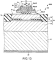
- Fig. 13 is a sectional view schematically illustrating a light source 100 of an atomic oscillator 3000 according to a second modification example of the present embodiment.
- Fig. 14 is a plan view schematically illustrating the light source 100 of an atomic oscillator 3000 according to a second modification example of the present embodiment. It should be noted that illustration of members other than the contacting part 62a of the fourth electrode 62, the heat diffusion layer 40, and the heat insulating layer 42, is omitted in Fig. 14 for convenience.
- the light source 100 of the atomic oscillator 3000 is different from the light source 100 of the above-described atomic oscillator 1000 in that this light source has the heat insulating layer 42.
- the area of the heat insulating layer 42 is smaller than the area of the heat diffusion layer 40.
- the heat insulating layer 42 in the plan view, is provided inside the outer edge of the heat diffusion layer 40.
- a space 6 is provided between the second reflective layer 24 and the heat diffusion layer 40.
- a diameter R1 of the heat insulating layer 42 has the same size as the external diameter of the contacting part 62a of the fourth electrode 62, and the diameter R1 is greater than an internal diameter R2 of the contacting part 62a.
- the area of the heat insulating layer 42 is greater than the area of an opening 162 defined by the contacting part 62a, and the opening 162 is provided inside an outer edge of the heat insulating layer 42.
- the diameter R1 of the heat insulating layer 42 is greater than the internal diameter of the opening provided in the current constriction layer 26.
- the heat insulating layer 42 can be adjusted in the diameter R1, for example, by being selectively etched with hydrogen fluoride (HF).
- HF hydrogen fluoride
- the area of the heat insulating layer 42 is smaller than the area of the heat diffusion layer 40. Therefore, in the atomic oscillator 3000, the space 6 is provided between the second reflective layer 24 and the heat diffusion layer 40. Accordingly, in the atomic oscillator 3000, even if the electrical field absorption layer 59 absorbs light to generate heat, the heat insulating layer 42 and the space 6 can insulate this heat, and can prevent this heat from reaching the second reflective layer 24 or the active layer 22.
- the area of the heat insulating layer 42 is greater than the area of the opening 162 defined by the contacting part 62a, and the opening 162 is provided inside the outer edge of the heat insulating layer 42. Therefore, in the atomic oscillator 3000, the light generated in the active layer 22 and exited from the upper surface of the second contact layer 54 can be prevented from passing through a boundary between the heat insulating layer 42 and the space 6. Accordingly, in the atomic oscillator 3000, scattering or loss of light in the boundary between the heat insulating layer 42 and the space 6 can be suppressed.
- the low thermal conductivity layer 43 having a lower thermal conductivity than that of the heat insulating layer 42 may be provided around the heat insulating layer 42.
- the heat insulating layer 42 may be surrounded by the low thermal conductivity layer 43.
- the low thermal conductivity layer 43 is provided between the second reflective layer 24 and the heat diffusion layer 40.
- the low thermal conductivity layer 43 is, for example, a polyimide layer.
- the thermal conductivity of polyimide is 0.018 W/(cm ⁇ K).
- the low thermal conductivity layer 43 is formed by, for example, a CVD method or a spin coating method.
- shock resistance can be improved compared with a case (a case illustrated in Fig. 13 ) where the space 6 is provided between the second reflective layer 24 and heat diffusion layer 40. Moreover, even if the electrical field absorption layer 59 absorbs light to generate heat, the heat insulating layer 42 and the low thermal conductivity layer 43 can insulate this heat, and can prevent this heat from reaching the second reflective layer 24 or the active layer 22.
- the invention may be provided by omitting a partial configuration in a range having the features and the effects described in the present application or combining each embodiment or the modification examples.
- the invention includes substantially the same configuration as the configuration described in the embodiment (for example, a configuration having the same functions, methods, and results as those of the configuration described in the embodiment, or a configuration having the same object and effects as those of the configuration described in the embodiment). Additionally, the invention includes a configuration in which parts that are not essential to the configuration described in the embodiment are substituted. Additionally, the invention includes a configuration in which the same functional effects as those of the configuration described in the embodiment can be exhibited or a configuration in which the same object as that of the configuration described in the embodiment can be achieved.
- the invention includes a configuration in which well-known techniques are added to the configuration described in the embodiment.
Abstract
Description
- The present invention relates to an atomic oscillator.
- An atomic oscillators using transition energy of atoms as reference frequency is widely used as one of highest-precision oscillators in communication base stations or the like. Although there are several types as the atomic oscillator, a microwave double resonance type using a rubidium (Rb) lamp is most generally used.
- In recent years, an atomic oscillator using a phenomenon called Coherent Population Trapping (CPT) that is one of quantum interference effects is suggested (for example, refer to
JP-A-2015-62167 - In order to develop the CPT phenomenon as the light source of the atomic oscillator, high-precision adjustment of the output wavelength of a laser element or the like is required. If an inflow current to the laser element or the like is changed, it is possible to adjust the output wavelength.
- However, if the inflow current to the laser element is changed, the optical output of the laser element or the like varies simultaneously. Therefore, it is necessary to form a control loop of the atomic oscillator in consideration of this, and complicated control is required. Therefore, a light source that can control its output wavelength and optical output individually is needed.
- An advantage of some aspects of the invention is to provide an atomic oscillator that can control the output wavelength and optical output of a light source individually.
- An atomic oscillator according to an aspect of the invention includes a gas cell having alkali metal atoms sealed therein; a light source that irradiates the gas cell with light; and a light detecting unit that detects the quantity of light transmitted through the gas cell. The light source includes an optical oscillation layer having a first reflective layer, an active layer, and a second reflective layer laminated therein in this order, an electrical field absorption layer having a first semiconductor layer, a quantum well layer, and a second semiconductor layer laminated therein in this order, and a heat diffusion layer that is disposed between the optical oscillation layer and the electrical field absorption layer and has a higher thermal conductivity than that of the second reflective layer.
- In such an atomic oscillator, in a case where the central wavelength of light exited from the light source is changed by changing the quantity of a current to be flowed into the active layer, even if the optical output (the quantity of light) of the light exited from the light source shifts from a predetermined value, the optical output of the light exited from the light source can be returned to the predetermined value by changing a voltage to be applied to the electrical field absorption layer. Moreover, in such an atomic oscillator, even if the electrical field absorption layer (the quantum well layer) absorbs light to generate heat, this heat can be diffused to the outside via the heat diffusion layer, and this heat can be prevented from reaching the second reflective layer or the active layer. Accordingly, a temperature change in the light source caused by the heat generated in the electrical field absorption layer can be suppressed. Therefore, the central wavelength of the light source can be prevented from fluctuating with temperature, and the output wavelength (central wavelength) and the optical output of the light source can be individually (independently) controlled depending on the quantity of an inflow current to the active layer, and a voltage applied to the electrical field absorption layer.
- In the atomic oscillator according to the aspect of the invention, the heat diffusion layer may be an i-type AlAs layer.
- In such an atomic oscillator, the heat diffusion layer can be formed in a series of processes (by the same apparatus as an apparatus for forming the optical oscillation layer and the electrical field absorption layer) together with the optical oscillation layer and the electrical field absorption layer.
- In the atomic oscillator according to the aspect of the invention, the heat diffusion layer may be an i-type GaAs layer.
- In such an atomic oscillator, the heat diffusion layer can be formed in a series of processes together with the optical oscillation layer and the electrical field absorption layer.
- The atomic oscillator according to the aspect of the invention may further include a contact layer provided between the heat diffusion layer and the first semiconductor layer, and a surface of the contact layer where the first semiconductor layer is disposed may be provided with an electrode for applying a voltage to the electrical field absorption layer.
- In such an atomic oscillator, the contact resistance of the electrode can be reduced compared to a case where the electrode is in direct contact with the first semiconductor layer.
- The invention will be described with reference to the accompanying drawings, wherein like numbers reference like elements.
-
Fig. 1 is a functional block diagram of an atomic oscillator according to the present embodiment. -
Fig. 2 is a view illustrating a frequency spectrum of resonance light. -
Fig. 3 is a view illustrating a relationship between a Λ-type three-level model of an alkali metal atom and a first sideband wave and a second sideband wave. -
Fig. 4 is a plan view schematically illustrating a light source of the atomic oscillator according to the present embodiment. -
Fig. 5 is a sectional view schematically illustrating the light source of the atomic oscillator according to the present embodiment. -
Fig. 6 is a sectional view schematically illustrating the light source of the atomic oscillator according to the present embodiment. -
Fig. 7 is a sectional view schematically illustrating the light source of the atomic oscillator according to the present embodiment. -
Fig. 8 is a circuit diagram for explaining the light source of the atomic oscillator according to the present embodiment. -
Fig. 9 is a sectional view schematically illustrating a process of manufacturing the light source of the atomic oscillator according to the present embodiment. -
Fig. 10 is a sectional view schematically illustrating a process of manufacturing the light source of the atomic oscillator according to the present embodiment. -
Fig. 11 is a sectional view schematically illustrating a process of manufacturing the light source of the atomic oscillator according to the present embodiment. -
Fig. 12 is a sectional view schematically illustrating a light source of an atomic oscillator according to a first modification example of the present embodiment. -
Fig. 13 is a sectional view schematically illustrating a light source of an atomic oscillator according to a second modification example of the present embodiment. -
Fig. 14 is a plan view schematically illustrating the light source of the atomic oscillator according to the second modification example of the present embodiment. -
Fig. 15 is a sectional view schematically illustrating the light source of the atomic oscillator according to the second modification example of the present embodiment. - A preferred embodiment of the invention will be described below in detail with reference to the drawings. It should be noted that the embodiment to be described below does not unduly limit the contents of the invention set forth in the appended claims. Additionally, all the components to be describing below are not necessarily indispensable constituent elements of the invention.
- First, an atomic oscillator according to the present embodiment will be described, referring to drawings.
Fig. 1 is a functional block diagram of anatomic oscillator 1000 according to the present embodiment. - The
atomic oscillator 1000, as illustrated inFig. 1 , includes thelight source 100, agas cell 102, light detecting means (light detecting unit) 104, a opticaloutput variable unit 106, a centralwavelength variable unit 108, a high-frequency generating unit 110, anabsorption detecting unit 112, anEIT detecting unit 114, and acontrol unit 120. Thecontrol unit 120 has an opticaloutput control unit 122, a central wavelength control unit 124, and a high-frequency control unit 126. Theatomic oscillator 1000 causes an EIT phenomenon in alkali metal atoms using a resonance light pair (first light and second light) having two different frequency components. - The
light source 100 generates the first light and the second light having mutually different frequencies, and irradiates alkali metal atoms sealed in thegas cell 102 with the first light and the second light. The detailed configuration of thelight source 100 will be described below. - Here,
Fig. 2 is a view illustrating a frequency spectrum of resonance light.Fig. 3 is a view illustrating a relationship between a Λ-type three-level model of alkali metal atoms, and a first sideband wave (first light) W1 and a second sideband wave (second light) W2. The light L exited from thelight source 100 includes a fundamental mode F having a central frequency f0 (= c/λ0: c is the speed of light, and λ0 is the central wavelength of laser light), the first sideband wave W1 having a frequency f1 in an upper sideband with respect to the central frequency f0, and the second sideband wave W2 having a frequency f2 in a lower sideband with respect to the central frequency f0, which are illustrated inFig. 2 . The frequency f1 of the first sideband wave W1 is f1 = f0 + fm, and the frequency f2 of the second sideband wave W2 is f2 = f0 - fm. - As illustrated in
Fig. 3 , a frequency difference between the frequency f1 of the first sideband wave W1 and the frequency f2 of the second sideband wave W2 coincides with a frequency equivalent to an energy difference ΔE12 of a ground level GL1 and a ground level GL2 of the alkali metal atoms. Therefore, the alkali metal atoms cause an EIT phenomenon due to the first sideband wave W1 having the frequency f1 and the second sideband wave W2 having the frequency f2. - Here, the EIT phenomenon will be described. It is known that an interaction between alkali metal atoms and light can be explained with a Λ-type three-level system model. As illustrated in
Fig. 3 , the alkali metal atoms have two ground levels, and if the first sideband wave W1 having a wavelength (frequency f1) equivalent to an energy difference between the ground level GL1 and an excitation level, or the second sideband wave W2 having a wavelength (frequency f2) equivalent to an energy difference between the ground level GL2 and the excitation level radiates the alkali metal atoms respectively and independently, optical absorption is caused. On the contrary, as illustrated inFig. 2 if the alkali metal atoms are simultaneously irradiated with the first sideband wave W1 and the second sideband wave W2 in which a frequency difference f1 - f2 exactly coincides with the frequency equivalent to the energy difference ΔE12 between the ground level GL1 and the ground level GL2, a superposition state of the two ground levels, that is, a quantum interference state is brought about. As a result, a transparency phenomenon (EIT phenomenon) in which excitation to the excitation level stops and the first sideband wave W1 and the second sideband wave W2 are transmitted through the alkali metal atoms. A high-precision oscillator can be built by using this EIT phenomenon and detecting and controlling a steep change in optical absorption behavior when the frequency difference f1 - f2 between the first sideband wave W1 and the second sideband wave W2 deviates from the frequency equivalent to the energy difference ΔE12 between the ground level GL1 and the ground level GL2. - The
gas cell 102 encloses gaseous alkali metal atoms (sodium atoms, rubidium atoms, cesium atoms, or the like) in a container. The cesium atoms are heated to, for example, about 80°C, and is turned into gas. If thisgas cell 102 is irradiated with two light waves (the first light and the second light) having a frequency (wavelength) equivalent to an energy difference between two ground levels of the alkali metal atoms, the alkali metal atoms cause the EIT phenomenon. For example, if the alkali metal atoms are cesium atoms, a frequency equivalent to the energy difference between the ground level GL1 and the ground level GL2 in line D1 is 9.19263···GHz. Thus, if two light waves of which the frequency difference is 9.19263···GHz, the EIT phenomenon is caused. - The
light detecting unit 104 detects the quantity (intensity) of light of light (transmitted through the alkali metal atoms sealed in the gas cell 102) transmitted through thegas cell 102. Thelight detecting unit 104 outputs a detection signal according to the quantity of the light transmitted through the alkali metal atoms. As thelight detecting unit 104, for example, a photodiode is used. - On the basis of the signal from the optical
output control unit 122, the opticaloutput variable unit 106 applies a voltage between theelectrodes 60 and 62 (refer toFig. 5 to be described below) of thelight source 100, and changes the optical output (quantity of light) of thelight source 100. The opticaloutput variable unit 106 may be configured to include the power source 4 (refer toFig. 8 to be described below) that applies a voltage between theelectrodes - On the basis of a signal from the central wavelength control unit 124, the central wavelength
variable unit 108 applies a voltage between theelectrodes 30 and 32 (refer toFig. 5 ) of thelight source 100, allows a current to flow into theactive layer 22, and changes the central wavelength of the light L exited from thelight source 100. Accordingly, the central wavelength of a resonance light pair (the first light and the second light) included in the light L can be changed. The central wavelengthvariable unit 108 may be configured to include the power source 2 (refer toFig. 8 ) that applies a voltage betweenelectrodes - On the basis of a signal from the high-
frequency control unit 126, the high-frequency generating unit 110 supplies a high-frequency signal between theelectrodes light source 100 to generate a resonance light pair. The high-frequency generating unit 110 may be realized by a dedicated circuit. - The
absorption detecting unit 112, for example, detects a minimum value (the bottom of absorption) of the signal intensity of a detection signal output from thelight detecting unit 104 when the central wavelength of the light L has been changed. Theabsorption detecting unit 112 may be realized by a dedicated circuit. - The
EIT detecting unit 114 synchronously detect the detection signal output from thelight detecting unit 104, and detects the EIT phenomenon. TheEIT detecting unit 114 may be realized by a dedicated circuit. - On the basis of an average (DC component) of the quantity of light of the detection signal output from the
light detecting unit 104, the opticaloutput control unit 122 controls the opticaloutput variable unit 106, thereby controlling a voltage to be applied to the electrical field absorption layer 59 (refer toFig, 5 ) of the light source 100 (applied to the quantum well layer 52) so as to change the quantity of absorbed light in the electrical field absorption layer 59 (in the quantum well layer 52). Accordingly, the opticaloutput control unit 122 can change the optical output (the quantity of light) of thelight source 100. The opticaloutput control unit 122 may control the opticaloutput variable unit 106, on the basis of a moving average of the quantity of light of the detection signal. The opticaloutput control unit 122 controls a voltage to be applied to the electricalfield absorption layer 59 such that the optical output exited from thelight source 100 becomes constant (for example, the DC component of the detection signal output from thelight detecting unit 104 becomes constant). The opticaloutput control unit 122 may be configured to include an auto power control (APC) circuit. - On the basis of a signal from the
absorption detecting unit 112, the central wavelength control unit 124 controls the central wavelengthvariable unit 108, thereby controlling a current to be flowed into the active layer 22 (refer toFig. 5 ) of thelight source 100 so as to change the optical output (the quantity of light) and the wavelength (central wavelength) of the light L exited from thelight source 100. - The high-
frequency control unit 126 inputs a signal to generate a high-frequency signal, to the high-frequency generating unit 110, on the basis of a signal from theEIT detecting unit 114. - It should be noted that the
control unit 120 may be configured to be realized by a dedicated circuit so as to perform the above control. Additionally, thecontrol unit 120 may be configured to function as, for example, a computer by a central processing unit (CPU) executing a control program stored in a storage, such as a read only memory (ROM) or a random access memory (RAM), so as to perform the above control. - Next, the operation of the
atomic oscillator 1000 will be described. First, the initial operation when starting theatomic oscillator 1000 in a stopped state will be described. - The high-
frequency control unit 126 inputs a signal to the high-frequency generating unit 110, and inputs a high-frequency signal from the high-frequency generating unit 110 to thelight source 100. In this case, the frequency of the high-frequency signal is slightly shifted such that the EIT phenomenon does not occur. For example, in a case where cesium is used as the alkali metal atoms of thegas cell 102, the frequency is shifted from the value of 4.596···GHz. - Next, the central wavelength control unit 124 controls the central wavelength
variable unit 108 to sweep the central wavelength of the light L. In this case, since the frequency of the high-frequency signal is set such that the EIT phenomenon does not occur, the EIT phenomenon does not occur. Theabsorption detecting unit 112 detects the minimum value (the bottom of absorption) of the intensity of a detection signal to be output in thelight detecting unit 104 when the central wavelength of the light L has been swept. Theabsorption detecting unit 112, for example, uses a point where a change in intensity of a detection signal with respect to the central wavelength of the light L, as the bottom of absorption. - If the
absorption detecting unit 112 detects the bottom of absorption, the central wavelength control unit 124 controls the central wavelengthvariable unit 108 to fix (lock) the central wavelength. That is, the central wavelength control unit 124 fixes the central wavelength of the light L to a wavelength equivalent to the bottom of absorption. - Next, the optical
output control unit 122 controls the opticaloutput variable unit 106 to change the optical output of thelight source 100, on the basis of the DC component of the detection signal output from thelight detecting unit 104. Specifically, the opticaloutput control unit 122 changes the optical output of thelight source 100 such that the DC component of the detection signal has a predetermined value. - Next, the high-
frequency control unit 126 controls the high-frequency generating unit 110 to match the frequency of the high-frequency signal with a frequency at which the EIT phenomenon occurs. Thereafter, the high-frequency control unit proceeds to a loop operation, and an EIT signal is detected by theEIT detecting unit 114. - Next, the loop operation of the
atomic oscillator 1000 will be described. - The
EIT detecting unit 114 synchronously detects the detection signal output from thelight detecting unit 104, and the high-frequency control unit 126 performs control such that the frequency of the high-frequency signal generated from the high-frequency generating unit 110 becomes a frequency equivalent to half of ΔE12 of the alkali metal atoms in thegas cell 102, on the basis of the signal input from theEIT detecting unit 114. - The
absorption detecting unit 112 synchronously detects the detection signal output from thelight detecting unit 104, and the central wavelength control unit 124 controls the central wavelengthvariable unit 108 such that the central wavelength of the light L becomes a wavelength equivalent to the minimum value (the bottom of absorption) of the intensity of a detection signal to be output in thelight detecting unit 104, on the basis of the signal input from theabsorption detecting unit 112. - The optical
output control unit 122 controls the opticaloutput variable unit 106 on the basis of the DC component of the detection signal output from thelight detecting unit 104. Specifically, in a case where the DC component of the detection signal becomes smaller than a predetermined value, the opticaloutput control unit 122 controls the opticaloutput variable unit 106 such that the DC component of the detection signal has a predetermined value. Even if the central wavelength of the light L deviates from the wavelength equivalent to the bottom of absorption through the control of the opticaloutput control unit 122, the central wavelength of the light L can be matched with the wavelength equivalent to the bottom of absorption through the control of the central wavelength control unit 124. Moreover, even if the DC component of the detection signal deviates from the predetermined value through the control of the central wavelength control unit 124, the DC component of the detection signal can be returned to the predetermined value through the control of the opticaloutput control unit 122. - In the
atomic oscillator 1000, control may be performed such that the temperature (driving temperature) of thelight source 100 becomes constant. - First, the
light source 100 of theatomic oscillator 1000 according to the present embodiment will be described, referring to drawings.Fig. 4 is a plan view schematically illustrating alight source 100 according to the present embodiment.Fig. 5 is a sectional view, taken along line V-V ofFig. 4 , schematically illustrating thelight source 100 according to the present embodiment.Fig. 6 is a sectional view, taken along line VI-VI ofFig. 4 , schematically illustrating thelight source 100 according to the present embodiment.Fig. 7 is a sectional view, taken along line VII-VII ofFig. 4 , schematically illustrating thelight source 100 according to the present embodiment.Fig. 8 is a circuit diagram for explaining thelight source 100 according to the present embodiment. - The
light source 100, as illustrated inFigs. 4 to 7 , includes asubstrate 10, a firstreflective layer 20, anactive layer 22, a secondreflective layer 24, acurrent constriction layer 26, afirst electrode 30, asecond electrode 32, aheat diffusion layer 40, afirst contact layer 50, afirst semiconductor layer 51, aquantum well layer 52, asecond semiconductor layer 53, asecond contact layer 54, athird electrode 60, afourth electrode 62, and insulatinglayers - The
substrate 10 is, for example, a first conductivity type (for example, n-type) GaAs substrate. - The first
reflective layer 20 is provided on thesubstrate 10. The firstreflective layer 20 is a first conductivity type semiconductor layer. The firstreflective layer 20 is a distribution Bragg reflector (DBR) mirror in which a high refractive-index layer and a low refractive-index layer having a lower refractive index than the high refractive-index layer are alternately laminated. The high refractive-index layer is, for example, an n-type Al0.12Ga0.88As layer. The low refractive-index layer is, for example, an n-type Al0.9Ga0.1As layer. The number (the number of pairs) of lamination of the high refractive-index layer and the low refractive-index layer is, for example, 10 pairs or more to 50 pairs or less, and specifically, 40.5 pairs. - The
active layer 22 is provided on the firstreflective layer 20. Theactive layer 22 has, for example, a multiplex quantum well (MQW) structure in which quantum well structures constituted of an i-type In0.06Ga0.94As layer and an i-type Al0.3Ga0.7As layer are superimposed on each other in three layers. - The second
reflective layer 24 is provided on theactive layer 22. The second reflective layer is a second conductivity type (for example, p-type) semiconductor layer. The secondreflective layer 24 is a distribution Bragg reflector (DBR) mirror in which a high refractive-index layer and a low refractive-index layer having a lower refractive index than the high refractive-index layer are alternately laminated. The high refractive-index layer is, for example, a p-type Al0.12Ga0.88As layer. The low refractive-index layer is, for example, a p-type Al0.9Ga0.1As layer. The number (the number of pairs) of lamination of the high refractive-index layer and the low refractive-index layer is, for example, 3 pairs or more to 40 pairs or less, and specifically, 20 pairs. - The second
reflective layer 24, theactive layer 22, and the firstreflective layer 20 constitute anoptical oscillation layer 29. Theoptical oscillation layer 29 is a laminated body in which the firstreflective layer 20, theactive layer 22, and the secondreflective layer 24 are laminated in this order. Theoptical oscillation layer 29 constitutes a perpendicular resonator type pin diode. As illustrated inFig. 8 , if a forward voltage of the pin diode 3 is applied between theelectrodes power source 2, the re-coupling of an electron and a positive hole occurs in theactive layer 22, and light emission occurs. The light generated in theactive layer 22 is bounced back and forth (multi-reflected) between the firstreflective layer 20 and the secondreflective layer 24, induced emission occurs in that case, and intensity is amplified. Then, if optical gain exceeds optical loss, laser oscillation occurs, and laser light is exited in a vertical direction (in a laminated direction of theactive layer 22 and the first reflective layer 20) from an upper surface of thesecond contact layer 54. The wavelength of this laser light is, for example, 800 nm or more to 950 nm or less, and specifically, 852 nm or 895 nm. - The
current constriction layer 26 is provided between the firstreflective layer 20 and the secondreflective layer 24. In an example illustrated inFig. 5 , thecurrent constriction layer 26 is provided on theactive layer 22. Thecurrent constriction layer 26 is an insulating layer in which an opening is formed, and this opening is provided with the secondreflective layer 24. A planar shape (a shape as seen from the laminated direction of theactive layer 22 and the first reflective layer 20) of thecurrent constriction layer 26 is ring-shaped. Thecurrent constriction layer 26 can prevent a current to be flowed into a perpendicular resonator by theelectrodes active layer 22 and the first reflective layer 20). - The
current constriction layer 26, the secondreflective layer 24, theactive layer 22, and the firstreflective layer 20 constitute acolumnar section 28. A planar shape of thecolumnar section 28 is, for example, circular. - The
first electrode 30 is provided under thesubstrate 10. Thefirst electrode 30 is provided, for example, on a lower surface of a layer (asubstrate 10 in the example illustrated inFig. 5 ) that comes in ohmic contact with thefirst electrode 30. Thefirst electrode 30 is electrically connected to the firstreflective layer 20. As thefirst electrode 30, for example, an electrode in which a Cr layer, an AuGe layer, an Ni layer, and an Au layer are laminated in this order from thesubstrate 10 side is used. Thefirst electrode 30 is one electrode to flow a current into theactive layer 22. - The
second electrode 32 is disposed on the secondreflective layer 24. Thesecond electrode 32 is electrically connected to the secondreflective layer 24. As thesecond electrode 32, for example, an electrode in which a Cr layer, a Pt layer, a Ti layer, a Pt layer, and an Au layer are laminated in this order from the secondreflective layer 24 side is used. Thesecond electrode 32 is the other electrode to flow a current into theactive layer 22. - The
second electrode 32, as illustrated inFig. 4 , has a contactingpart 32a, a lead-outpart 32b, and apad part 32c. The contactingpart 32a is in contact with the secondreflective layer 24. In the example illustrated inFig. 4 , a planar shape of the contactingpart 32a is a shape obtained by cutting off a portion of a ring shape. A planar shape of the lead-outpart 32b is, for example, linear. The lead-outpart 32b connects the contactingpart 32a and thepad part 32c together. The lead-outpart 32b and thepad part 32c are provided on an insulatinglayer 70. Thepad part 32c is connected to external wiring or the like serving as an electrode pad. In the illustrated example, a planar shape of thepad part 32c is circular. The insulatinglayer 70 is provided so as to surround thecolumnar section 28 in contact with, for example, a side surface of thecolumnar section 28. The insulatinglayer 70 is, for example, a polyimide layer or a silicon oxide layer. - The
second electrode 32, the secondreflective layer 24, theactive layer 22, the firstreflective layer 20, and thefirst electrode 30 constitute a vertical cavity surface emitting laser (VCSEL). - The
heat diffusion layer 40 is disposed on the secondreflective layer 24. Theheat diffusion layer 40 is disposed between the secondreflective layer 24 and the first contact layer 50 (between theoptical oscillation layer 29 and an electrical field absorption layer 59). A planar shape of theheat diffusion layer 40 is, for example, circular. In the plan view (as seen in the laminated direction of theactive layer 22 and the first reflective layer 20), the area ofheat diffusion layer 40 is smaller than the area of an upper surface of the secondreflective layer 24, andheat diffusion layer 40 is provided inside an outer edge of the secondreflective layer 24. The thermal conductivity of theheat diffusion layer 40 is higher than the thermal conductivity of the secondreflective layer 24. Specifically, the thermal conductivity of theheat diffusion layer 40 is higher than the thermal conductivity of the high refractive-index layer that constitutes the secondreflective layer 24, and is lower than the thermal conductivity of the low refractive-index layer that constitutes the secondreflective layer 24. Theheat diffusion layer 40 is, for example, an i-type AlAs layer, or an i-type GaAs layer. For example, the thermal conductivity of i-type GaAs is 0.55 W/(cm·K). - The
first contact layer 50 is disposed on theheat diffusion layer 40. Thefirst contact layer 50 is provided between theheat diffusion layer 40 and thefirst semiconductor layer 51. In the example illustrated inFig. 4 , a planar shape of thefirst contact layer 50 is circular. In the plan view, the area of thefirst contact layer 50 and the area of theheat diffusion layer 40 are, for example, the same as each other. Thefirst contact layer 50 is, for example, a p-type GaAs layer. - The
first semiconductor layer 51 is provided on thefirst contact layer 50. A planar shape of thefirst semiconductor layer 51 is, for example, circular. In the plan view, the area of thefirst semiconductor layer 51 is smaller than the area of an upper surface of thefirst contact layer 50, and thefirst semiconductor layer 51 is provided inside an outer edge of thefirst contact layer 50. Thefirst semiconductor layer 51 is, for example, a p-type Al0.3Ga0.7As layer. - The
quantum well layer 52 is provided on thefirst semiconductor layer 51. Thequantum well layer 52 has a multiplex quantum well (MQW) structure in which three quantum well structures constituted of an i-type GaAs well layer and an i-type Al0.3Ga0.7As barrier layer are superimposed on each other. - The
second semiconductor layer 53 is provided on thequantum well layer 52. Thesecond semiconductor layer 53 is, for example, an n-type Al0.3Ga0.7As layer. The semiconductor layers 51 and 53 are layers that have a greater band gap and a smaller refractive index than thequantum well layer 52. - The
second semiconductor layer 53, thequantum well layer 52, and thefirst semiconductor layer 51 constitute the electricalfield absorption layer 59. The electricalfield absorption layer 59 is a laminated body in which thefirst semiconductor layer 51, thequantum well layer 52, and thesecond semiconductor layer 53 are laminated in this order. The electricalfield absorption layer 59 constitutes the pin diode (pin photodiode). As illustrated inFig. 8 , if a backward voltage of thepin diode 5 is applied between theelectrodes power source 4, light can be absorbed in thequantum well layer 52. Accordingly, light (laser light generated in a vertical cavity surface emitting laser) generated in theoptical oscillation layer 29 can be absorbed. The quantity of absorption of light in thequantum well layer 52 can be adjusted depending on the magnitude of a voltage to be applied to the electricalfield absorption layer 59. - It should be noted that the pin photodiode configured to include the electrical
field absorption layer 59 may take out or may not take out a photocurrent caused by an electron and a positive hole that are excited by absorbing light in thequantum well layer 52, to an external circuit as a signal. - Here, if a voltage is applied to the electrical
field absorption layer 59, the absorption wavelength (absorption peak wavelength) of the electricalfield absorption layer 59 shifts to a longer wavelength side due to the quantum confined Stark effect compared to the case where no voltage is applied. Therefore, in a state where no voltage is applied to the electricalfield absorption layer 59, the absorption peak wavelength in the electricalfield absorption layer 59 is set closer to a shorter wavelength side than the oscillation wavelength in the optical oscillation layer 29 (vertical cavity surface emitting laser). Then, by applying a voltage to the electricalfield absorption layer 59, the absorption peak wavelength of the electricalfield absorption layer 59 is shifted, and the light generated in theoptical oscillation layer 29 is absorbed. - For example, in a case where the oscillation wavelength in the
optical oscillation layer 29 is 852 nm, the absorption peak wavelength (quantum well layer 52) of the electricalfield absorption layer 59 reaches 800 nm in a state where no voltage is applied. In this case, as thequantum well layer 52, there is used quantum well layer having a multiplex quantum well (MQW) structure in which three quantum well structures constituted of a GaAs well layer with a thickness of 4 nm and an Al0.3Ga0.7As barrier layer with a thickness of 10 nm are superimposed on each other. - The
second contact layer 54 is provided on thesecond semiconductor layer 53. In the example illustrated inFig. 4 , a planar shape of thesecond contact layer 54 is circular. A material for thesecond contact layer 54 is, for example, a n-type GaAs layer. - The
third electrode layer 60 is provided on thefirst contact layer 50. Thethird electrode 60 is provided on a surface where thefirst semiconductor layer 51 of thefirst contact layer 50 is disposed. Thethird electrode 60 is electrically connected to thefirst semiconductor layer 51. For example, thethird electrode 60 comes in ohmic contact with thefirst contact layer 50. A material for thethird electrode 60 is, for example, the same as a material for thesecond electrode 32. Thethird electrode 60 is one electrode for applying a voltage to the electricalfield absorption layer 59. - The
third electrode 60, as illustrated inFig. 4 , has a contactingpart 60a and apad part 60c. The contactingpart 60a is in contact with thefirst contact layer 50. In the example illustrated inFig. 4 , the contactingpart 60a has a shape obtained by cutting off a part of a ring shape in the plan view, and is provided so as to surround thesecond contact layer 54. - The
pad part 60c of thethird electrode 60 is connected to, for example, the contactingpart 60a. Thepad part 60c has afirst portion 601 and asecond portion 602. In the plan view, the area of thefirst portion 601 is greater than the area of thepad part 32c of thesecond electrode 32 and the area of thepad part 62c of thefourth electrode 62. In the plan view, the area of thesecond portion 602 is greater than the area of thepad part 32c and the area of thepad part 62c. In an illustrated example, planar shapes of thefirst portion 601 and thesecond portion 602 are substantially quadrangular. In the plan view, thefirst portion 601 and thesecond portion 602 may be provided point-symmetrically with respect to the center of thesecond contact layer 54. - The
pad part 60c of thethird electrode 60 is provided on the insulatinglayer 72. Thepad part 60c is connected to external wiring or the like serving as an electrode pad. The insulatinglayer 72, as illustrated inFig. 7 , is provided on the insulatinglayer 70 in contact with side surfaces of theheat diffusion layer 40 and thefirst contact layer 50. A material for the insulatinglayer 72 is, for example, the same as a material for the insulatinglayer 70. - The
fourth electrode 62 is provided on thesecond contact layer 54. Thefourth electrode 62 is electrically connected to thesecond semiconductor layer 53. For example, thefourth electrode 62 comes in ohmic contact with thesecond contact layer 54. A material for thefourth electrode 62 is, for example, the same as a material for thefirst electrode 30. Thefourth electrode 62 is the other electrode for applying a voltage to the electricalfield absorption layer 59. - The
fourth electrode 62, as illustrated inFig. 4 , has a contactingpart 62a, a lead-outpart 62b, and apad part 62c. The contactingpart 62a is in contact with thesecond contact layer 54. In the example illustrated inFig. 4 , a planar shape of the contactingpart 62a is ring-shaped. A planar shape of the lead-outpart 62b is, for example, linear. The lead-outpart 62b connects the contactingpart 62a and thepad part 62c together. The lead-outpart 62b and thepad part 62c are provided on an insulatinglayer 74. Thepad part 62c is connected to external wiring or the like serving as an electrode pad. In the illustrated example, a planar shape of thepad part 62c is circular. The insulatinglayer 74, as illustrated inFig. 6 , is provided on the insulatinglayer 72 in contact with side surfaces of the electricalfield absorption layer 59 and thesecond contact layer 54. A material for the insulatinglayer 74 is, for example, the same as a material for the insulatinglayer 70. - Although not illustrated, the insulating
layer 72 may be provided so as to surround theheat diffusion layer 40 and thefirst contact layer 50, or the insulatinglayer 74 may be provided so as to surround the electricalfield absorption layer 59 and thesecond contact layer 54. - Additionally, although the AlGaAs-based light source has been described above, for example, a GaInP-based, ZnSSe-based, InGaN-based, AlGaN-based, InGaAs-based, GaInNAs-based, or GaAsSb-based semiconductor material may be used for the light source, according to oscillation wavelength.
- Next, a method for manufacturing the
light source 100 according to the present embodiment will be described, referring to drawings.Figs. 9 to 11 are sectional views schematically illustrating a process of manufacturing thelight source 100 according to the present embodiment. - As illustrated in
Fig. 9 , the firstreflective layer 20, theactive layer 22, the oxidizedlayer 26a that is oxidized and partially serves as thecurrent constriction layer 26, the secondreflective layer 24, theheat diffusion layer 40, thefirst contact layer 50, thefirst semiconductor layer 51, thequantum well layer 52, thesecond semiconductor layer 53, and thesecond contact layer 54 are epitaxially grown in this order on thesubstrate 10. The epitaxial growing method includes, for example, a metal organic chemical vapor deposition (MOCVD) method, and a molecular beam epitaxy (MBE) method. - As illustrated in
Fig. 10 , thesecond contact layer 54, thesecond semiconductor layer 53, thequantum well layer 52, thefirst semiconductor layer 51, thefirst contact layer 50, theheat diffusion layer 40, the secondreflective layer 24, the oxidizedlayer 26a, theactive layer 22, and the firstreflective layer 20 are patterned in a predetermined shape. Patterning is performed by, for example, photolithography or etching. Thesecond contact layer 54, thesecond semiconductor layer 53, thequantum well layer 52, and thefirst semiconductor layer 51 may be patterned in the same process (for example, simultaneously). Thefirst contact layer 50 and theheat diffusion layer 40 may be patterned in the same process. The secondreflective layer 24, the oxidizedlayer 26a, theactive layer 22, and the firstreflective layer 20 may be patterned in the same process. The order of patterning the respective layers is not limited particularly. Thecolumnar section 28 can be formed by the present process. - As illustrated in
Fig. 11 , thecurrent constriction layer 26 is formed by oxidizing a portion of the oxidizedlayer 26a. The oxidizedlayer 26a is, for example, an AlxGa1-xAs (x ≥ 0.95) layer. For example, by charging thesubstrate 10 in that each layer is formed in a steam atmosphere of about 400°C, thecurrent constriction layer 26 is formed by oxidizing theoxidized layer 26a from a side surface. In the present process, a side surface of theheat diffusion layer 40 is covered with a resist (not illustrated) or the like such that theheat diffusion layer 40 is not oxidized. - As illustrated in
Fig. 5 , the insulatinglayer 70 is formed around thecolumnar section 28. In other words, in a plan view of thecolumnar section 28, thecolumnar section 28 is surrounded by the insulatinglayer 70. The insulatinglayer 70 is formed, for example, by film formation using a spin coating method or a CVD method, or by patterning. Patterning is performed by, for example, photolithography or etching. - As illustrated in
Figs. 6 and7 , the insulatinglayers layer 70. The insulating layers 72 and 74 are formed, for example, by film formation using a spin coating method or a CVD method, or by patterning. Patterning is performed by, for example, photolithography or etching. - As illustrated in
Fig. 5 , thefirst electrode 30 is formed under thesubstrate 10, thesecond electrode 32 is formed on the secondreflective layer 24, thethird electrode 60 is formed on thefirst contact layer 50, and thefourth electrode 62 is formed on thesecond contact layer 54. Theelectrodes electrodes - The
light source 100 can be manufactured by the above process. - The
atomic oscillator 1000 has, for example, the following features. - In the
atomic oscillator 1000, thelight source 100 has theoptical oscillation layer 29 in which the firstreflective layer 20, theactive layer 22, and the secondreflective layer 24 are laminated in this order, and the electricalfield absorption layer 59 in which thefirst semiconductor layer 51, thequantum well layer 52, and thesecond semiconductor layer 53 are laminated in this order. Therefore, in theatomic oscillator 1000, in a case where the central wavelength of light (light exited from the upper surface of the second contact layer 54) exited from thelight source 100 is changed by changing the quantity of a current to be flowed into theactive layer 22, even if the optical output (the quantity of light) of the light exited from thelight source 100 deviates from a predetermined value, the optical output of the light exited from thelight source 100 can be returned to the predetermined value by changing a voltage to be applied to the electrical field absorption layer 59 (to the quantum well layer 52). - Moreover, the
light source 100 of theatomic oscillator 1000 has theheat diffusion layer 40 that is disposed between theoptical oscillation layer 29 and the electricalfield absorption layer 59, and has a higher thermal conductivity than that of the secondreflective layer 24. Therefore, even if the electrical field absorption layer 59 (the quantum well layer 52) absorbs light to generate heat, this heat can be diffused to the outside via theheat diffusion layer 40, and this heat can be prevented from reaching the secondreflective layer 24 or theactive layer 22. Specifically, the heat generated in the electricalfield absorption layer 59 is released to the outside via thefirst contact layer 50, theheat diffusion layer 40, the contactingpart 60a, and thepad part 60c. Accordingly, in theatomic oscillator 1000, a temperature change in thelight source 100 caused by the heat generated in the electricalfield absorption layer 59 can be suppressed. Therefore, in theatomic oscillator 1000, the central wavelength of thelight source 100 can be prevented from fluctuating with temperature, and the output wavelength and the optical output of thelight source 100 can be individually (independently) controlled depending on the quantity of an inflow current to theactive layer 22, and a voltage applied to the electricalfield absorption layer 59. In theatomic oscillator 1000, for example, in order to make the central wavelength of thelight source 100 constant, it is necessary to control the driving temperature of thelight source 100 in units of tens of mK, and the control of temperature can be made easy by providing theheat diffusion layer 40. - Moreover, even in a case where the light source is driven with the quantity of a current to be flowed into the active layer being constant and the driving temperature of the light source being constant, the output wavelength and the optical output of the light source may vary in the long term. Even in this case, in the
atomic oscillator 1000, the output wavelength and the optical output of thelight source 100 can be individually controlled by thelight source 100, and the long-term stability of theatomic oscillator 1000 can be improved. - In the
light source 100 of theatomic oscillator 1000, theheat diffusion layer 40 is an i-type AlAs layer or an i-type GaAs layer. Therefore, theheat diffusion layer 40 can be formed in a series of processes (for example, in the same MOCVD apparatus) together with theoptical oscillation layer 29 and the electricalfield absorption layer 59. - In the
light source 100 of theatomic oscillator 1000, thethird electrode 60 for applying a voltage to the electricalfield absorption layer 59 is provided on the surface where thefirst semiconductor layer 51 of thefirst contact layer 50 is disposed. Therefore, in theatomic oscillator 1000, the contact resistance of thethird electrode 60 can be reduced compared to a case where thethird electrode 60 is in direct contact with thefirst semiconductor layer 51. - Next, an atomic oscillator according to a first modification example of the present embodiment will be described, referring to drawings.
Fig. 12 is a sectional view schematically illustrating alight source 100 of anatomic oscillator 2000 according to a first modification example of the present embodiment. - Hereinafter, in the
atomic oscillator 2000 according to the first modification example of the present embodiment, members having the same functions as those of the constituent members of theatomic oscillator 1000 according to the present embodiment will be designated by the same reference signs, and the detailed description thereof will be omitted. The same applies to an atomic oscillator according to a second modification example of the present embodiment to be described below. - The
light source 100 of theatomic oscillator 2000, as illustrated inFig. 12 , is different from thelight source 100 of the above-describedatomic oscillator 1000 in that this light source has theheat insulating layer 42. - The
heat insulating layer 42 is provided on the secondreflective layer 24. Theheat insulating layer 42 is provided between the secondreflective layer 24 and theheat diffusion layer 40. A planar shape of theheat insulating layer 42 is, for example, circular. In the plan view, the area of theheat insulating layer 42 and the area of theheat diffusion layer 40 are, for example, the same as each other. The thermal conductivity of theheat insulating layer 42 is lower than the thermal conductivity of the secondreflective layer 24. Specifically, the thermal conductivity of theheat insulating layer 42 is lower than the thermal conductivity of the high refractive-index layer that constitutes the secondreflective layer 24, and is lower than the thermal conductivity of the low refractive-index layer that constitutes the secondreflective layer 24. Theheat insulating layer 42 is, for example, an aluminum oxide layer (AlxOy layer). For example, the thermal conductivity of Al2O3 is 0.3 W/(cm·K). - The
heat insulating layer 42 is formed, for example, by oxidizing an AlAs layer. A process of oxidizing an AlAs layer to form theheat insulating layer 42 may be performed simultaneously with a process of forming thecurrent constriction layer 26. The AlAs layer used as theheat insulating layer 42 is formed by, for example, an MOCVD method. - The
light source 100 of theatomic oscillator 2000 has theheat insulating layer 42 having a lower thermal conductivity than that of the secondreflective layer 24 between the secondreflective layer 24 and theheat diffusion layer 40. Therefore, in theatomic oscillator 2000, even if the electricalfield absorption layer 59 absorbs light to generate heat, theheat insulating layer 42 can insulate this heat, and can prevent this heat from reaching the secondreflective layer 24 or theactive layer 22. - Next, an atomic oscillator according to a second modification example of the present embodiment will be described, referring to drawings.
Fig. 13 is a sectional view schematically illustrating alight source 100 of anatomic oscillator 3000 according to a second modification example of the present embodiment.Fig. 14 is a plan view schematically illustrating thelight source 100 of anatomic oscillator 3000 according to a second modification example of the present embodiment. It should be noted that illustration of members other than the contactingpart 62a of thefourth electrode 62, theheat diffusion layer 40, and theheat insulating layer 42, is omitted inFig. 14 for convenience. - The
light source 100 of theatomic oscillator 3000, as illustrated inFigs. 13 and14 , is different from thelight source 100 of the above-describedatomic oscillator 1000 in that this light source has theheat insulating layer 42. - In the
light source 100 of theatomic oscillator 3000, in the plan view, the area of theheat insulating layer 42 is smaller than the area of theheat diffusion layer 40. Theheat insulating layer 42, in the plan view, is provided inside the outer edge of theheat diffusion layer 40. Aspace 6 is provided between the secondreflective layer 24 and theheat diffusion layer 40. In the illustrated example, in the plan view, a diameter R1 of theheat insulating layer 42 has the same size as the external diameter of the contactingpart 62a of thefourth electrode 62, and the diameter R1 is greater than an internal diameter R2 of the contactingpart 62a. In the plan view, the area of theheat insulating layer 42 is greater than the area of anopening 162 defined by the contactingpart 62a, and theopening 162 is provided inside an outer edge of theheat insulating layer 42. Moreover, in the illustrated example, in the plan view, the diameter R1 of theheat insulating layer 42 is greater than the internal diameter of the opening provided in thecurrent constriction layer 26. - The
heat insulating layer 42 can be adjusted in the diameter R1, for example, by being selectively etched with hydrogen fluoride (HF). When theheat insulating layer 42 is etched with the hydrogen fluoride, thecurrent constriction layer 26 is protected by a resist or the like. - In the
light source 100 of theatomic oscillator 3000, in the plan view, the area of theheat insulating layer 42 is smaller than the area of theheat diffusion layer 40. Therefore, in theatomic oscillator 3000, thespace 6 is provided between the secondreflective layer 24 and theheat diffusion layer 40. Accordingly, in theatomic oscillator 3000, even if the electricalfield absorption layer 59 absorbs light to generate heat, theheat insulating layer 42 and thespace 6 can insulate this heat, and can prevent this heat from reaching the secondreflective layer 24 or theactive layer 22. - In the
light source 100 of theatomic oscillator 3000, in the plan view, the area of theheat insulating layer 42 is greater than the area of theopening 162 defined by the contactingpart 62a, and theopening 162 is provided inside the outer edge of theheat insulating layer 42. Therefore, in theatomic oscillator 3000, the light generated in theactive layer 22 and exited from the upper surface of thesecond contact layer 54 can be prevented from passing through a boundary between theheat insulating layer 42 and thespace 6. Accordingly, in theatomic oscillator 3000, scattering or loss of light in the boundary between theheat insulating layer 42 and thespace 6 can be suppressed. - It should be noted that, as illustrated in
Fig. 15 , the lowthermal conductivity layer 43 having a lower thermal conductivity than that of theheat insulating layer 42 may be provided around theheat insulating layer 42. In other words, in a plan view of theheat insulating layer 42, theheat insulating layer 42 may be surrounded by the lowthermal conductivity layer 43. The lowthermal conductivity layer 43 is provided between the secondreflective layer 24 and theheat diffusion layer 40. The lowthermal conductivity layer 43 is, for example, a polyimide layer. For example, the thermal conductivity of polyimide is 0.018 W/(cm·K). The lowthermal conductivity layer 43 is formed by, for example, a CVD method or a spin coating method. By providing the lowthermal conductivity layer 43, shock resistance can be improved compared with a case (a case illustrated inFig. 13 ) where thespace 6 is provided between the secondreflective layer 24 andheat diffusion layer 40. Moreover, even if the electricalfield absorption layer 59 absorbs light to generate heat, theheat insulating layer 42 and the lowthermal conductivity layer 43 can insulate this heat, and can prevent this heat from reaching the secondreflective layer 24 or theactive layer 22. - The invention may be provided by omitting a partial configuration in a range having the features and the effects described in the present application or combining each embodiment or the modification examples.
- The invention includes substantially the same configuration as the configuration described in the embodiment (for example, a configuration having the same functions, methods, and results as those of the configuration described in the embodiment, or a configuration having the same object and effects as those of the configuration described in the embodiment). Additionally, the invention includes a configuration in which parts that are not essential to the configuration described in the embodiment are substituted. Additionally, the invention includes a configuration in which the same functional effects as those of the configuration described in the embodiment can be exhibited or a configuration in which the same object as that of the configuration described in the embodiment can be achieved.
- Additionally, the invention includes a configuration in which well-known techniques are added to the configuration described in the embodiment.
Claims (4)
- An atomic oscillator comprising:a gas cell having alkali metal atoms sealed therein;a light source that irradiates the gas cell with light; anda light detecting unit that detects the quantity of light transmitted through the gas cell,wherein the light source includes
an optical oscillation layer having a first reflective layer, an active layer, and a second reflective layer laminated therein in this order,
an electrical field absorption layer having a first semiconductor layer, a quantum well layer, and a second semiconductor layer laminated therein in this order, and
a heat diffusion layer that is disposed between the optical oscillation layer and the electrical field absorption layer and has a higher thermal conductivity than that of the second reflective layer. - The atomic oscillator according to claim 1,
wherein the heat diffusion layer is an i-type AlAs layer. - The atomic oscillator according to claim 1 or claim 2,
wherein the heat diffusion layer is an i-type GaAs layer. - The atomic oscillator according to any of claims 1-3, further comprising:a contact layer provided between the heat diffusion layer and the first semiconductor layer,wherein a surface of the contact layer where the first semiconductor layer is disposed is provided with an electrode for applying a voltage to the electrical field absorption layer.
Applications Claiming Priority (1)
| Application Number | Priority Date | Filing Date | Title |
|---|---|---|---|
| JP2015210824A JP6705151B2 (en) | 2015-10-27 | 2015-10-27 | Atomic oscillator |
Publications (2)
| Publication Number | Publication Date |
|---|---|
| EP3171232A1 true EP3171232A1 (en) | 2017-05-24 |
| EP3171232B1 EP3171232B1 (en) | 2018-10-24 |
Family
ID=57208137
Family Applications (1)
| Application Number | Title | Priority Date | Filing Date |
|---|---|---|---|
| EP16195500.0A Not-in-force EP3171232B1 (en) | 2015-10-27 | 2016-10-25 | Atomic oscillator |
Country Status (4)
| Country | Link |
|---|---|
| US (1) | US10097191B2 (en) |
| EP (1) | EP3171232B1 (en) |
| JP (1) | JP6705151B2 (en) |
| CN (1) | CN107017881B (en) |
Families Citing this family (1)
| Publication number | Priority date | Publication date | Assignee | Title |
|---|---|---|---|---|
| JP6939344B2 (en) * | 2017-09-28 | 2021-09-22 | セイコーエプソン株式会社 | Atomic oscillators and systems |
Citations (4)
| Publication number | Priority date | Publication date | Assignee | Title |
|---|---|---|---|---|
| US20020176459A1 (en) * | 2001-05-25 | 2002-11-28 | Martinsen Robert Jens | Method and apparatus for controlling thermal variations in an optical device |
| US20070002917A1 (en) * | 2005-06-30 | 2007-01-04 | Finisar Corporation | Electro-absorption modulator integrated with a vertical cavity surface emitting laser |
| JP2015062167A (en) | 2013-08-20 | 2015-04-02 | 株式会社リコー | Heater substrate, alkali metal cell unit, and atomic oscillator |
| WO2015137174A1 (en) * | 2014-03-14 | 2015-09-17 | Ricoh Company, Ltd. | Surface emitting laser, surface emitting laser element and atomic oscillator |
Family Cites Families (20)
| Publication number | Priority date | Publication date | Assignee | Title |
|---|---|---|---|---|
| JPH09283836A (en) | 1996-04-09 | 1997-10-31 | Matsushita Electric Ind Co Ltd | Surface emission semiconductor laser device |
| JP2003202529A (en) * | 2001-03-13 | 2003-07-18 | Ricoh Co Ltd | Semiconductor optical modulator, semiconductor light emitting device and wavelength variable laser device and multiwavelength laser device and optical transmission system |
| CN100364192C (en) * | 2003-04-28 | 2008-01-23 | 松下电器产业株式会社 | Semiconductor light-emitting device and method for manufacturing same |
| JP4101838B2 (en) * | 2003-07-29 | 2008-06-18 | 三菱電機株式会社 | Solid-state laser excitation module and laser oscillator |
| JP2005197549A (en) * | 2004-01-09 | 2005-07-21 | Yokogawa Electric Corp | Surface emission laser |
| JP2006216862A (en) * | 2005-02-04 | 2006-08-17 | Nec Corp | Modulator-integrated surface emission laser |
| JP4940987B2 (en) * | 2006-03-20 | 2012-05-30 | 日亜化学工業株式会社 | Nitride semiconductor laser device and manufacturing method thereof |
| US7593436B2 (en) * | 2006-06-16 | 2009-09-22 | Vi Systems Gmbh | Electrooptically Bragg-reflector stopband-tunable optoelectronic device for high-speed data transfer |
| JP2009010248A (en) * | 2007-06-29 | 2009-01-15 | Canon Inc | Surface emitting laser and method of manufacturing the same |
| JP2009088445A (en) * | 2007-10-03 | 2009-04-23 | Seiko Epson Corp | Optical component |
| US20090256638A1 (en) * | 2008-03-28 | 2009-10-15 | Michael Rosenbluh | Atomic frequency standard based on enhanced modulation efficiency semiconductor lasers |
| WO2009125635A1 (en) * | 2008-04-08 | 2009-10-15 | 日本電気株式会社 | Semiconductor laser and modulation method of semiconductor laser |
| JP5532679B2 (en) * | 2008-07-03 | 2014-06-25 | セイコーエプソン株式会社 | Atomic oscillator optical system and atomic oscillator |
| CN101667715B (en) * | 2008-09-03 | 2010-10-27 | 中国科学院半导体研究所 | Single-mode high-power vertical cavity surface emitting laser and manufacturing method thereof |
| JP5256999B2 (en) * | 2008-10-29 | 2013-08-07 | セイコーエプソン株式会社 | Physical part of atomic oscillator |
| JP5407570B2 (en) * | 2009-06-09 | 2014-02-05 | セイコーエプソン株式会社 | Atomic oscillator |
| JP5540619B2 (en) * | 2009-09-16 | 2014-07-02 | セイコーエプソン株式会社 | Control method of atomic oscillator |
| JP5892320B2 (en) * | 2012-01-11 | 2016-03-23 | セイコーエプソン株式会社 | Optical module and atomic oscillator for an atomic oscillator |
| JP6119295B2 (en) * | 2013-02-18 | 2017-04-26 | セイコーエプソン株式会社 | Quantum interference device, atomic oscillator, and moving object |
| JP6323649B2 (en) * | 2013-12-20 | 2018-05-16 | セイコーエプソン株式会社 | Surface emitting laser and atomic oscillator |
-
2015
- 2015-10-27 JP JP2015210824A patent/JP6705151B2/en active Active
-
2016
- 2016-10-21 CN CN201610921948.XA patent/CN107017881B/en active Active
- 2016-10-24 US US15/332,185 patent/US10097191B2/en active Active
- 2016-10-25 EP EP16195500.0A patent/EP3171232B1/en not_active Not-in-force
Patent Citations (4)
| Publication number | Priority date | Publication date | Assignee | Title |
|---|---|---|---|---|
| US20020176459A1 (en) * | 2001-05-25 | 2002-11-28 | Martinsen Robert Jens | Method and apparatus for controlling thermal variations in an optical device |
| US20070002917A1 (en) * | 2005-06-30 | 2007-01-04 | Finisar Corporation | Electro-absorption modulator integrated with a vertical cavity surface emitting laser |
| JP2015062167A (en) | 2013-08-20 | 2015-04-02 | 株式会社リコー | Heater substrate, alkali metal cell unit, and atomic oscillator |
| WO2015137174A1 (en) * | 2014-03-14 | 2015-09-17 | Ricoh Company, Ltd. | Surface emitting laser, surface emitting laser element and atomic oscillator |
Also Published As
| Publication number | Publication date |
|---|---|
| JP2017084937A (en) | 2017-05-18 |
| EP3171232B1 (en) | 2018-10-24 |
| JP6705151B2 (en) | 2020-06-03 |
| US10097191B2 (en) | 2018-10-09 |
| CN107017881B (en) | 2021-06-01 |
| CN107017881A (en) | 2017-08-04 |
| US20170117911A1 (en) | 2017-04-27 |
Similar Documents
| Publication | Publication Date | Title |
|---|---|---|
| US9748739B2 (en) | Vertical cavity surface emitting laser and atomic oscillator | |
| US10103515B2 (en) | Vertical cavity surface emitting laser and atomic oscillator | |
| US9397478B2 (en) | Vertical cavity surface emitting laser and atomic oscillator | |
| US9197034B2 (en) | Vertical cavity surface emitting laser and atomic oscillator | |
| US9300308B2 (en) | Light emitting device and atomic oscillator | |
| US9257816B2 (en) | Vertical cavity surface emitting laser and atomic oscillator | |
| US9634467B2 (en) | Vertical cavity surface emitting laser and atomic oscillator | |
| US20150180206A1 (en) | Vertical cavity surface emitting laser and atomic oscillator | |
| EP3171232B1 (en) | Atomic oscillator | |
| US10326256B2 (en) | Surface emitting laser and atomic oscillator | |
| US20150180212A1 (en) | Vertical cavity surface emitting laser and atomic oscillator | |
| EP3163691A1 (en) | Light source and atomic oscillator | |
| US10224943B2 (en) | Atomic oscillator | |
| JP2015119150A (en) | Vertical cavity surface emitting laser and atomic oscillator | |
| JP2015119148A (en) | Vertical cavity surface emitting laser and atomic oscillator |
Legal Events
| Date | Code | Title | Description |
|---|---|---|---|
| PUAI | Public reference made under article 153(3) epc to a published international application that has entered the european phase |
Free format text: ORIGINAL CODE: 0009012 |
|
| AK | Designated contracting states |
Kind code of ref document: A1 Designated state(s): AL AT BE BG CH CY CZ DE DK EE ES FI FR GB GR HR HU IE IS IT LI LT LU LV MC MK MT NL NO PL PT RO RS SE SI SK SM TR |
|
| AX | Request for extension of the european patent |
Extension state: BA ME |
|
| 17P | Request for examination filed |
Effective date: 20171108 |
|
| RBV | Designated contracting states (corrected) |
Designated state(s): AL AT BE BG CH CY CZ DE DK EE ES FI FR GB GR HR HU IE IS IT LI LT LU LV MC MK MT NL NO PL PT RO RS SE SI SK SM TR |
|
| GRAP | Despatch of communication of intention to grant a patent |
Free format text: ORIGINAL CODE: EPIDOSNIGR1 |
|
| INTG | Intention to grant announced |
Effective date: 20180629 |
|
| GRAS | Grant fee paid |
Free format text: ORIGINAL CODE: EPIDOSNIGR3 |
|
| GRAA | (expected) grant |
Free format text: ORIGINAL CODE: 0009210 |
|
| AK | Designated contracting states |
Kind code of ref document: B1 Designated state(s): AL AT BE BG CH CY CZ DE DK EE ES FI FR GB GR HR HU IE IS IT LI LT LU LV MC MK MT NL NO PL PT RO RS SE SI SK SM TR |
|
| REG | Reference to a national code |
Ref country code: FR Ref legal event code: PLFP Year of fee payment: 3 |
|
| REG | Reference to a national code |
Ref country code: CH Ref legal event code: EP |
|
| REG | Reference to a national code |
Ref country code: IE Ref legal event code: FG4D |
|
| REG | Reference to a national code |
Ref country code: AT Ref legal event code: REF Ref document number: 1057408 Country of ref document: AT Kind code of ref document: T Effective date: 20181115 |
|
| REG | Reference to a national code |
Ref country code: DE Ref legal event code: R096 Ref document number: 602016006616 Country of ref document: DE |
|
| REG | Reference to a national code |
Ref country code: NL Ref legal event code: MP Effective date: 20181024 |
|
| REG | Reference to a national code |
Ref country code: LT Ref legal event code: MG4D |
|
| REG | Reference to a national code |
Ref country code: AT Ref legal event code: MK05 Ref document number: 1057408 Country of ref document: AT Kind code of ref document: T Effective date: 20181024 |
|
| PG25 | Lapsed in a contracting state [announced via postgrant information from national office to epo] |
Ref country code: NL Free format text: LAPSE BECAUSE OF FAILURE TO SUBMIT A TRANSLATION OF THE DESCRIPTION OR TO PAY THE FEE WITHIN THE PRESCRIBED TIME-LIMIT Effective date: 20181024 |
|
| PG25 | Lapsed in a contracting state [announced via postgrant information from national office to epo] |
Ref country code: LV Free format text: LAPSE BECAUSE OF FAILURE TO SUBMIT A TRANSLATION OF THE DESCRIPTION OR TO PAY THE FEE WITHIN THE PRESCRIBED TIME-LIMIT Effective date: 20181024 Ref country code: FI Free format text: LAPSE BECAUSE OF FAILURE TO SUBMIT A TRANSLATION OF THE DESCRIPTION OR TO PAY THE FEE WITHIN THE PRESCRIBED TIME-LIMIT Effective date: 20181024 Ref country code: LT Free format text: LAPSE BECAUSE OF FAILURE TO SUBMIT A TRANSLATION OF THE DESCRIPTION OR TO PAY THE FEE WITHIN THE PRESCRIBED TIME-LIMIT Effective date: 20181024 Ref country code: PL Free format text: LAPSE BECAUSE OF FAILURE TO SUBMIT A TRANSLATION OF THE DESCRIPTION OR TO PAY THE FEE WITHIN THE PRESCRIBED TIME-LIMIT Effective date: 20181024 Ref country code: BG Free format text: LAPSE BECAUSE OF FAILURE TO SUBMIT A TRANSLATION OF THE DESCRIPTION OR TO PAY THE FEE WITHIN THE PRESCRIBED TIME-LIMIT Effective date: 20190124 Ref country code: NO Free format text: LAPSE BECAUSE OF FAILURE TO SUBMIT A TRANSLATION OF THE DESCRIPTION OR TO PAY THE FEE WITHIN THE PRESCRIBED TIME-LIMIT Effective date: 20190124 Ref country code: AT Free format text: LAPSE BECAUSE OF FAILURE TO SUBMIT A TRANSLATION OF THE DESCRIPTION OR TO PAY THE FEE WITHIN THE PRESCRIBED TIME-LIMIT Effective date: 20181024 Ref country code: HR Free format text: LAPSE BECAUSE OF FAILURE TO SUBMIT A TRANSLATION OF THE DESCRIPTION OR TO PAY THE FEE WITHIN THE PRESCRIBED TIME-LIMIT Effective date: 20181024 Ref country code: IS Free format text: LAPSE BECAUSE OF FAILURE TO SUBMIT A TRANSLATION OF THE DESCRIPTION OR TO PAY THE FEE WITHIN THE PRESCRIBED TIME-LIMIT Effective date: 20190224 Ref country code: ES Free format text: LAPSE BECAUSE OF FAILURE TO SUBMIT A TRANSLATION OF THE DESCRIPTION OR TO PAY THE FEE WITHIN THE PRESCRIBED TIME-LIMIT Effective date: 20181024 |
|
| PG25 | Lapsed in a contracting state [announced via postgrant information from national office to epo] |
Ref country code: PT Free format text: LAPSE BECAUSE OF FAILURE TO SUBMIT A TRANSLATION OF THE DESCRIPTION OR TO PAY THE FEE WITHIN THE PRESCRIBED TIME-LIMIT Effective date: 20190224 Ref country code: GR Free format text: LAPSE BECAUSE OF FAILURE TO SUBMIT A TRANSLATION OF THE DESCRIPTION OR TO PAY THE FEE WITHIN THE PRESCRIBED TIME-LIMIT Effective date: 20190125 Ref country code: RS Free format text: LAPSE BECAUSE OF FAILURE TO SUBMIT A TRANSLATION OF THE DESCRIPTION OR TO PAY THE FEE WITHIN THE PRESCRIBED TIME-LIMIT Effective date: 20181024 Ref country code: SE Free format text: LAPSE BECAUSE OF FAILURE TO SUBMIT A TRANSLATION OF THE DESCRIPTION OR TO PAY THE FEE WITHIN THE PRESCRIBED TIME-LIMIT Effective date: 20181024 Ref country code: AL Free format text: LAPSE BECAUSE OF FAILURE TO SUBMIT A TRANSLATION OF THE DESCRIPTION OR TO PAY THE FEE WITHIN THE PRESCRIBED TIME-LIMIT Effective date: 20181024 |
|
| REG | Reference to a national code |
Ref country code: BE Ref legal event code: MM Effective date: 20181031 |
|
| PG25 | Lapsed in a contracting state [announced via postgrant information from national office to epo] |
Ref country code: LU Free format text: LAPSE BECAUSE OF NON-PAYMENT OF DUE FEES Effective date: 20181025 |
|
| REG | Reference to a national code |
Ref country code: IE Ref legal event code: MM4A |
|
| REG | Reference to a national code |
Ref country code: DE Ref legal event code: R097 Ref document number: 602016006616 Country of ref document: DE |
|
| PG25 | Lapsed in a contracting state [announced via postgrant information from national office to epo] |
Ref country code: CZ Free format text: LAPSE BECAUSE OF FAILURE TO SUBMIT A TRANSLATION OF THE DESCRIPTION OR TO PAY THE FEE WITHIN THE PRESCRIBED TIME-LIMIT Effective date: 20181024 Ref country code: IT Free format text: LAPSE BECAUSE OF FAILURE TO SUBMIT A TRANSLATION OF THE DESCRIPTION OR TO PAY THE FEE WITHIN THE PRESCRIBED TIME-LIMIT Effective date: 20181024 Ref country code: DK Free format text: LAPSE BECAUSE OF FAILURE TO SUBMIT A TRANSLATION OF THE DESCRIPTION OR TO PAY THE FEE WITHIN THE PRESCRIBED TIME-LIMIT Effective date: 20181024 |
|
| PG25 | Lapsed in a contracting state [announced via postgrant information from national office to epo] |
Ref country code: SM Free format text: LAPSE BECAUSE OF FAILURE TO SUBMIT A TRANSLATION OF THE DESCRIPTION OR TO PAY THE FEE WITHIN THE PRESCRIBED TIME-LIMIT Effective date: 20181024 Ref country code: SK Free format text: LAPSE BECAUSE OF FAILURE TO SUBMIT A TRANSLATION OF THE DESCRIPTION OR TO PAY THE FEE WITHIN THE PRESCRIBED TIME-LIMIT Effective date: 20181024 Ref country code: EE Free format text: LAPSE BECAUSE OF FAILURE TO SUBMIT A TRANSLATION OF THE DESCRIPTION OR TO PAY THE FEE WITHIN THE PRESCRIBED TIME-LIMIT Effective date: 20181024 Ref country code: BE Free format text: LAPSE BECAUSE OF NON-PAYMENT OF DUE FEES Effective date: 20181031 Ref country code: MC Free format text: LAPSE BECAUSE OF FAILURE TO SUBMIT A TRANSLATION OF THE DESCRIPTION OR TO PAY THE FEE WITHIN THE PRESCRIBED TIME-LIMIT Effective date: 20181024 Ref country code: RO Free format text: LAPSE BECAUSE OF FAILURE TO SUBMIT A TRANSLATION OF THE DESCRIPTION OR TO PAY THE FEE WITHIN THE PRESCRIBED TIME-LIMIT Effective date: 20181024 |
|
| PLBE | No opposition filed within time limit |
Free format text: ORIGINAL CODE: 0009261 |
|
| STAA | Information on the status of an ep patent application or granted ep patent |
Free format text: STATUS: NO OPPOSITION FILED WITHIN TIME LIMIT |
|
| 26N | No opposition filed |
Effective date: 20190725 |
|
| PG25 | Lapsed in a contracting state [announced via postgrant information from national office to epo] |
Ref country code: SI Free format text: LAPSE BECAUSE OF FAILURE TO SUBMIT A TRANSLATION OF THE DESCRIPTION OR TO PAY THE FEE WITHIN THE PRESCRIBED TIME-LIMIT Effective date: 20181024 Ref country code: IE Free format text: LAPSE BECAUSE OF NON-PAYMENT OF DUE FEES Effective date: 20181025 |
|
| PGFP | Annual fee paid to national office [announced via postgrant information from national office to epo] |
Ref country code: FR Payment date: 20190913 Year of fee payment: 4 |
|
| PG25 | Lapsed in a contracting state [announced via postgrant information from national office to epo] |
Ref country code: MT Free format text: LAPSE BECAUSE OF NON-PAYMENT OF DUE FEES Effective date: 20181025 |
|
| PGFP | Annual fee paid to national office [announced via postgrant information from national office to epo] |
Ref country code: DE Payment date: 20191015 Year of fee payment: 4 |
|
| PG25 | Lapsed in a contracting state [announced via postgrant information from national office to epo] |
Ref country code: TR Free format text: LAPSE BECAUSE OF FAILURE TO SUBMIT A TRANSLATION OF THE DESCRIPTION OR TO PAY THE FEE WITHIN THE PRESCRIBED TIME-LIMIT Effective date: 20181024 |
|
| REG | Reference to a national code |
Ref country code: CH Ref legal event code: PL |
|
| PG25 | Lapsed in a contracting state [announced via postgrant information from national office to epo] |
Ref country code: HU Free format text: LAPSE BECAUSE OF FAILURE TO SUBMIT A TRANSLATION OF THE DESCRIPTION OR TO PAY THE FEE WITHIN THE PRESCRIBED TIME-LIMIT; INVALID AB INITIO Effective date: 20161025 Ref country code: MK Free format text: LAPSE BECAUSE OF NON-PAYMENT OF DUE FEES Effective date: 20181024 Ref country code: CY Free format text: LAPSE BECAUSE OF FAILURE TO SUBMIT A TRANSLATION OF THE DESCRIPTION OR TO PAY THE FEE WITHIN THE PRESCRIBED TIME-LIMIT Effective date: 20181024 |
|
| PG25 | Lapsed in a contracting state [announced via postgrant information from national office to epo] |
Ref country code: LI Free format text: LAPSE BECAUSE OF NON-PAYMENT OF DUE FEES Effective date: 20191031 Ref country code: CH Free format text: LAPSE BECAUSE OF NON-PAYMENT OF DUE FEES Effective date: 20191031 |
|
| REG | Reference to a national code |
Ref country code: DE Ref legal event code: R119 Ref document number: 602016006616 Country of ref document: DE |
|
| GBPC | Gb: european patent ceased through non-payment of renewal fee |
Effective date: 20201025 |
|
| PG25 | Lapsed in a contracting state [announced via postgrant information from national office to epo] |
Ref country code: DE Free format text: LAPSE BECAUSE OF NON-PAYMENT OF DUE FEES Effective date: 20210501 Ref country code: FR Free format text: LAPSE BECAUSE OF NON-PAYMENT OF DUE FEES Effective date: 20201031 |
|
| PG25 | Lapsed in a contracting state [announced via postgrant information from national office to epo] |
Ref country code: GB Free format text: LAPSE BECAUSE OF NON-PAYMENT OF DUE FEES Effective date: 20201025 |