EP3171217B1 - Unité de verre de recouvrement de caméra à fonction d'élimination de l'eau - Google Patents
Unité de verre de recouvrement de caméra à fonction d'élimination de l'eau Download PDFInfo
- Publication number
- EP3171217B1 EP3171217B1 EP15194934.4A EP15194934A EP3171217B1 EP 3171217 B1 EP3171217 B1 EP 3171217B1 EP 15194934 A EP15194934 A EP 15194934A EP 3171217 B1 EP3171217 B1 EP 3171217B1
- Authority
- EP
- European Patent Office
- Prior art keywords
- cover glass
- permanent magnet
- camera
- motor
- magnet
- Prior art date
- Legal status (The legal status is an assumption and is not a legal conclusion. Google has not performed a legal analysis and makes no representation as to the accuracy of the status listed.)
- Active
Links
- 239000006059 cover glass Substances 0.000 title claims description 91
- XLYOFNOQVPJJNP-UHFFFAOYSA-N water Substances O XLYOFNOQVPJJNP-UHFFFAOYSA-N 0.000 title description 12
- 239000000463 material Substances 0.000 claims description 6
- 229910001172 neodymium magnet Inorganic materials 0.000 claims description 3
- 239000011521 glass Substances 0.000 description 3
- 238000012544 monitoring process Methods 0.000 description 3
- 239000003292 glue Substances 0.000 description 2
- 230000003993 interaction Effects 0.000 description 2
- 230000002776 aggregation Effects 0.000 description 1
- 238000004220 aggregation Methods 0.000 description 1
- 238000001514 detection method Methods 0.000 description 1
- 230000000694 effects Effects 0.000 description 1
- 239000012530 fluid Substances 0.000 description 1
- 230000006872 improvement Effects 0.000 description 1
- 229910052500 inorganic mineral Inorganic materials 0.000 description 1
- 239000011707 mineral Substances 0.000 description 1
- 230000004048 modification Effects 0.000 description 1
- 238000012986 modification Methods 0.000 description 1
- 239000004033 plastic Substances 0.000 description 1
- 229920003023 plastic Polymers 0.000 description 1
- 229920003229 poly(methyl methacrylate) Polymers 0.000 description 1
- 239000004417 polycarbonate Substances 0.000 description 1
- 229920000515 polycarbonate Polymers 0.000 description 1
- 239000004926 polymethyl methacrylate Substances 0.000 description 1
- 230000004044 response Effects 0.000 description 1
- 229910000859 α-Fe Inorganic materials 0.000 description 1
Images

Classifications
-
- G—PHYSICS
- G03—PHOTOGRAPHY; CINEMATOGRAPHY; ANALOGOUS TECHNIQUES USING WAVES OTHER THAN OPTICAL WAVES; ELECTROGRAPHY; HOLOGRAPHY
- G03B—APPARATUS OR ARRANGEMENTS FOR TAKING PHOTOGRAPHS OR FOR PROJECTING OR VIEWING THEM; APPARATUS OR ARRANGEMENTS EMPLOYING ANALOGOUS TECHNIQUES USING WAVES OTHER THAN OPTICAL WAVES; ACCESSORIES THEREFOR
- G03B11/00—Filters or other obturators specially adapted for photographic purposes
- G03B11/04—Hoods or caps for eliminating unwanted light from lenses, viewfinders or focusing aids
- G03B11/045—Lens hoods or shields
-
- G—PHYSICS
- G02—OPTICS
- G02B—OPTICAL ELEMENTS, SYSTEMS OR APPARATUS
- G02B27/00—Optical systems or apparatus not provided for by any of the groups G02B1/00 - G02B26/00, G02B30/00
- G02B27/0006—Optical systems or apparatus not provided for by any of the groups G02B1/00 - G02B26/00, G02B30/00 with means to keep optical surfaces clean, e.g. by preventing or removing dirt, stains, contamination, condensation
-
- G—PHYSICS
- G03—PHOTOGRAPHY; CINEMATOGRAPHY; ANALOGOUS TECHNIQUES USING WAVES OTHER THAN OPTICAL WAVES; ELECTROGRAPHY; HOLOGRAPHY
- G03B—APPARATUS OR ARRANGEMENTS FOR TAKING PHOTOGRAPHS OR FOR PROJECTING OR VIEWING THEM; APPARATUS OR ARRANGEMENTS EMPLOYING ANALOGOUS TECHNIQUES USING WAVES OTHER THAN OPTICAL WAVES; ACCESSORIES THEREFOR
- G03B17/00—Details of cameras or camera bodies; Accessories therefor
- G03B17/56—Accessories
-
- B—PERFORMING OPERATIONS; TRANSPORTING
- B08—CLEANING
- B08B—CLEANING IN GENERAL; PREVENTION OF FOULING IN GENERAL
- B08B11/00—Cleaning flexible or delicate articles by methods or apparatus specially adapted thereto
- B08B11/04—Cleaning flexible or delicate articles by methods or apparatus specially adapted thereto specially adapted for plate glass, e.g. prior to manufacture of windshields
-
- G—PHYSICS
- G03—PHOTOGRAPHY; CINEMATOGRAPHY; ANALOGOUS TECHNIQUES USING WAVES OTHER THAN OPTICAL WAVES; ELECTROGRAPHY; HOLOGRAPHY
- G03B—APPARATUS OR ARRANGEMENTS FOR TAKING PHOTOGRAPHS OR FOR PROJECTING OR VIEWING THEM; APPARATUS OR ARRANGEMENTS EMPLOYING ANALOGOUS TECHNIQUES USING WAVES OTHER THAN OPTICAL WAVES; ACCESSORIES THEREFOR
- G03B11/00—Filters or other obturators specially adapted for photographic purposes
-
- G—PHYSICS
- G03—PHOTOGRAPHY; CINEMATOGRAPHY; ANALOGOUS TECHNIQUES USING WAVES OTHER THAN OPTICAL WAVES; ELECTROGRAPHY; HOLOGRAPHY
- G03B—APPARATUS OR ARRANGEMENTS FOR TAKING PHOTOGRAPHS OR FOR PROJECTING OR VIEWING THEM; APPARATUS OR ARRANGEMENTS EMPLOYING ANALOGOUS TECHNIQUES USING WAVES OTHER THAN OPTICAL WAVES; ACCESSORIES THEREFOR
- G03B17/00—Details of cameras or camera bodies; Accessories therefor
- G03B17/56—Accessories
- G03B17/565—Optical accessories, e.g. converters for close-up photography, tele-convertors, wide-angle convertors
-
- H—ELECTRICITY
- H02—GENERATION; CONVERSION OR DISTRIBUTION OF ELECTRIC POWER
- H02K—DYNAMO-ELECTRIC MACHINES
- H02K7/00—Arrangements for handling mechanical energy structurally associated with dynamo-electric machines, e.g. structural association with mechanical driving motors or auxiliary dynamo-electric machines
- H02K7/003—Couplings; Details of shafts
Definitions
- the present invention relates to a camera cover glass unit which is arranged to remove water from a camera cover glass.
- Monitoring cameras are commonly used to monitor building, roads, shops and various other places. In particular, cameras are often used to monitor scenes to allow automatic detection or tracking of events in the form of presence of motion or presence of an object of a specific type. Such monitoring cameras can be used both indoors and outdoors. A monitoring camera mounted outdoors is sometimes exposed to harsh weather conditions such as wind, snow and rain. A common problem which occurs when rain drops are present in the view of the camera is that these by mistake trigger alarms. This typically happens when the camera is unable to separate a small object close by, such as a rain drop trickling down the cover glass of the camera lens, from a larger object more far away, such as a car or a person moving at a distance from the camera.
- a cover glass unit comprises the features defined in independent claim 1.
- the movement of the cover glass will cause rain drops on the cover glass to move down along the glass and disappear from the view of the camera, thereby providing a better image quality.
- the rotation of the second magnet in relation to the first magnet will cause a roughly circular motion, not only a linear, back-and-forth motion. This will cause the rain drops to move not only downwards, but also towards each other sideways, and thereby cause aggregation of the water drops into larger drops, which more easily will move down the cover glass. In this way a more efficient removal of water from the cover glass is achieved.
- the motor may be a dc motor, which is a cost efficient and fail safe option, which additionally will reduce the risk of causing sparks which may damage the sensitive electronic and optic devices in the camera.
- the second magnet may conveniently be arranged on a rotation axle of the dc motor.
- the motor may be mounted on the cover glass frame. This provides for a compact mounting solution.
- the motor is preferably arranged to rotate the second magnet at a frequency of less than 100 Hz, and particularly at a frequency of 40-70 Hz. This will move water drops down the cover glass, while still allowing the drops to aggregate as they move sideways in response to the roughly circular motion of the cover glass, thereby collecting also small drops and efficiently clearing the cover glass from water.
- a higher frequency than 100 Hz is less efficient as water drops will not have time to move sideways to gather into larger drops and capture the smaller drops between them.
- a frequency lower than 40 Hz would be too slow and would not cause any movement of the water drops in relation to the surface of the cover glass.
- the motor may be arranged to rotate the second magnet in a plane parallel to a plane of the cover glass, and additionally, or as an alternative, the motor may be arranged to rotate the second magnet in a plane non-coinciding with the plane of the cover glass.
- the motor may be arranged to rotate the second magnet to either cause a two-dimensional movement of the cover glass, when the second magnet rotates in the same plane as the cover glass, or cause a three-dimensional movement of the cover glass, either by rotating the second magnet in a plane parallel to, but displaced from the plane of the cover glass, or by rotating the second magnet in a plane which is inclined to, or at an angle to, the plane of the cover glass.
- the first magnet may be mounted at an edge of the cover glass, thereby allowing it to be close to the second magnet when this is mounted on or near the frame. Placing the first magnet as close to the second magnet as possible will make the magnetic force between them stronger, allowing for smaller magnets to be used.
- the first magnet may be fully or partially embedded in the cover glass, which allows the first magnet to be more or less hidden from sight and giving an attractive appearance of the cover glass.
- the mounting of the cover glass in the resilient structure in the frame may also be simplified by the first magnet being mounted flush with the surface of the cover glass.
- One or both of the first magnet and the second magnet may be neodymium magnets. As this material is very strongly magnetic, it allows for using small magnets which are easy to mount.
- the resilient structure is preferably bellow shaped. Such a shape allows for movement of the cover glass in several directions.
- the resilient structure may conveniently comprise a rubber material, which provides a flexible material which also is resistant to water.
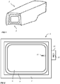
- Figs 1 and 2 show a camera 1 with a cover glass unit 3.
- the cover glass unit 3 includes a cover glass 5 which is mounted in a frame 7 via a resilient structure 9, in this example in the form of a bellow shaped rubber gasket. Other materials and shapes of the resilient structure may also be used, provided that they allow the cover glass 5 to move in relation to the frame 7.
- the cover glass 5 can e.g. be made of some type of mineral glass, or a plastic material such as polycarbonate or acrylic glass.
- the cover glass protects an image capturing unit (not shown) of the camera from the environment.
- a first permanent magnet 11 is attached to the cover glass 5.
- the first permanent magnet 11 is attached to an edge of the glass, but it could also be mounted on some type of structure, such as an arm or a pin, extending from the cover glass 5.
- the first magnet 11 can be fully or partly embedded in the cover glass 5. It can be attached to the cover glass 5 e.g. via glue or a screw joint.
- the first magnet 11 is shown as being mounted with its magnetic axis perpendicular to the closest edge of the cover glass 5, with its south pole closest to frame 7. However, this placing is merely an example.
- the first magnet 11 could be placed in any convenient way, such as parallel to the edge of the cover glass 5, or at any angle to the edge of the cover glass 5.
- the cover glass unit 3 further includes a motor 13, which is arranged to rotate a second permanent magnet 15.
- a motor 13 which is arranged to rotate a second permanent magnet 15.
- the second magnet 15 may be mounted directly on the rotation axle of the motor 13, but it may also be mounted on a separate device which is operatively connected to the rotational axle of the motor 13, and driven to rotate by the motor 13.
- the option shown in the accompanying drawings is where the second magnet 15 is mounted directly on the rotation axle of the motor 13.
- the second magnet 15 may e.g. be attached to the rotation axle by glue, clamps, a press fit or any other suitable means.
- the motor 13 is in turn mounted on the frame 7 or on some other location which is fix in relation to the cover glass 5, such as on a housing of the camera 1.
- the first magnet 11 and the second magnet 15 are usually neodymium magnets, but other choices such as ferrite magnets are also possible.
- both the first and the second magnet are illustrated in the shape of bar magnets.
- the first and the second magnets could be of any shape and form, e.g. bars, cylinders, rods, discs or spheres. Either way, the rotation of the second magnet 15 creates a time-variant magnetic field affecting the first magnet 11.
- the first magnet 11 and the second magnet 15 repels and attracts each other to a varying degree as the motor 13 rotates the second magnet 15, and this in turn causes the cover glass 5 to move in a roughly circular and back-and-forth fashion in relation to the frame 7.
- the motor 13 is normally set to rotate the second magnet at a rotational frequency of less than 100 Hz, and usually at a frequency of 40-70 Hz, as this gives a movement of the window which has been seen to help moving the rain drops in an efficient manner off the cover glass.
- Fig. 3 illustrates the interaction between the first magnet 11 and the second magnet 15 in some exemplifying rotational positions of the second magnet 15.
- the arrows roughly symbolize the size and the direction of the forces acting on the first magnet 11 at different rotational positions of the second magnet 15.
- Fig. 4 the arrows illustrate the resulting movement caused in the cover glass 5 by the interaction between the two magnets 11, 15 during rotation of the motor 13.
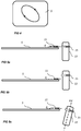
- Figs 5a-c Some different options for the mounting of the second magnet 15 and the motor 13 are illustrated in Figs 5a-c .
- the second magnet rotates in a plane which coincides with the plane of the cover glass 5, or more precisely the plane of the first magnet 11.
- This mounting option will cause a movement of the cover glass in the described roughly circular fashion in two dimensions.
- the cover glass 5 could also be made to perform a movement in three dimensions. This can be achieved by mounting the motor 13 with the second magnet 15 according to the options shown in Fig. 5b or 5c .
- the second magnet 15 rotates in a plane parallel to, but displaced from the plane of the cover glass 5, or, more precisely, the plane parallel to the cover glass 5 in which the first magnet's magnetic axis A is located.
- Fig. 5c another variant is shown where the second magnet 15 and the motor 13 is mounted such that the rotation axis B of the motor, and the second magnet 15, is inclined in relation to the plane of the cover glass 5.
- Both or one of the first and the second magnet may e.g. comprise two or more magnets, mounted in such a fashion that a similar motion of the cover glass to what has been described is still achieved.
Claims (12)
- Unité de verre recouvrement de caméra, comprenant:un verre de recouvrement (5), agencé pour protéger une unité de capture d'image d'une caméra (1),un cadre de verre de recouvrement (7), agencé pour retenir le verre de recouvrement (5),une structure résiliente (9), montée entre le verre de recouvrement et le cadre de verre de recouvrement, et permettant au verre de recouvrement de se déplacer par rapport au cadre de verre de recouvrement,un premier aimant permanent (11), fixé au verre de recouvrement,un second aimant permanent (15),un moteur (13) agencé pour faire tourner le second aimant permanent par rapport au premier aimant permanent, de manière à obtenir un champ magnétique variable dans le temps, de sorte que le second aimant permanent attire et repousse le premier aimant permanent dans un degré variable, en amenant ainsi le verre de recouvrement à se déplacer par rapport au cadre.
- Unité de verre de recouvrement de caméra selon la revendication 2, dans laquelle le second aimant permanent (15) est agencé sur un axe de rotation du moteur dc.
- Unité de verre de recouvrement de caméra selon la revendication 2, dans laquelle le second aimant permanent (15) est agencé sur un axe de rotation du moteur dc.
- Unité de verre de recouvrement de caméra selon une quelconque des revendications précédentes, dans laquelle le moteur (13) est monté sur le cadre de verre de recouvrement (7).
- Unité de verre de recouvrement de caméra selon une quelconque des revendications précédentes, dans laquelle le moteur (13) est agencé pour faire tourner le second aimant permanent (15) à une fréquence inférieure à 100 Hz, et de préférence à 40-70 Hz.
- Unité de verre de recouvrement de caméra selon une des revendications précédentes, dans laquelle le moteur (13) est agencé pour faire tourner le second aimant permanent (15) dans un plan parallèle à un plan du verre de recouvrement (5).
- Unité de verre de recouvrement de caméra selon une des revendications précédentes, dans laquelle le moteur est agencé pour faire tourner le second aimant permanent (15) dans un plan non coïncident avec un plan du verre de recouvrement (5).
- Unité de verre de recouvrement de caméra selon une des revendications précédentes, dans laquelle le premier aimant permanent (11) est monté au niveau d'un bord du verre de recouvrement (5).
- Unité de verre de recouvrement de caméra selon une des revendications précédentes, dans laquelle le premier aimant permanent (11) est totalement ou partiellement incorporé dans le verre de recouvrement (5).
- Unité de verre de recouvrement de caméra selon une des revendications précédentes, dans laquelle un ou les deux du premier aimant permanent (11) et l'aimant permanent (15) sont des aimants au néodyme.
- Unité de verre de recouvrement de caméra selon une des revendications précédentes, dans laquelle la structure résiliente (9) est en forme de soufflet.
- Unité de verre de recouvrement de caméra selon une des revendications précédentes, dans laquelle la structure résiliente (9) comprend un matériau caoutchouteux.
Priority Applications (6)
| Application Number | Priority Date | Filing Date | Title |
|---|---|---|---|
| EP15194934.4A EP3171217B1 (fr) | 2015-11-17 | 2015-11-17 | Unité de verre de recouvrement de caméra à fonction d'élimination de l'eau |
| TW105135432A TWI696031B (zh) | 2015-11-17 | 2016-11-02 | 具有除水功能之攝像機外罩玻璃單元 |
| US15/344,913 US10394021B2 (en) | 2015-11-17 | 2016-11-07 | Camera cover glass unit with water removal function |
| JP2016219684A JP6360868B2 (ja) | 2015-11-17 | 2016-11-10 | 水分除去機能を有するカメラカバーガラスユニット |
| KR1020160150326A KR20170057839A (ko) | 2015-11-17 | 2016-11-11 | 물 제거 기능을 구비한 카메라 커버 글라스 유닛 |
| CN201610999402.6A CN106707665B (zh) | 2015-11-17 | 2016-11-14 | 具有除水功能的摄像机盖玻璃单元 |
Applications Claiming Priority (1)
| Application Number | Priority Date | Filing Date | Title |
|---|---|---|---|
| EP15194934.4A EP3171217B1 (fr) | 2015-11-17 | 2015-11-17 | Unité de verre de recouvrement de caméra à fonction d'élimination de l'eau |
Publications (2)
| Publication Number | Publication Date |
|---|---|
| EP3171217A1 EP3171217A1 (fr) | 2017-05-24 |
| EP3171217B1 true EP3171217B1 (fr) | 2017-10-25 |
Family
ID=54557316
Family Applications (1)
| Application Number | Title | Priority Date | Filing Date |
|---|---|---|---|
| EP15194934.4A Active EP3171217B1 (fr) | 2015-11-17 | 2015-11-17 | Unité de verre de recouvrement de caméra à fonction d'élimination de l'eau |
Country Status (6)
| Country | Link |
|---|---|
| US (1) | US10394021B2 (fr) |
| EP (1) | EP3171217B1 (fr) |
| JP (1) | JP6360868B2 (fr) |
| KR (1) | KR20170057839A (fr) |
| CN (1) | CN106707665B (fr) |
| TW (1) | TWI696031B (fr) |
Families Citing this family (9)
| Publication number | Priority date | Publication date | Assignee | Title |
|---|---|---|---|---|
| US10317776B2 (en) | 2016-05-13 | 2019-06-11 | Sol Pals, Llc | Camera obstructing device |
| USD810180S1 (en) * | 2016-05-13 | 2018-02-13 | Sol Pals, Llc | Webcam cover |
| USD940720S1 (en) | 2017-04-25 | 2022-01-11 | C-Slide Holdings, Llc | Mic block with leash hole |
| WO2018200058A1 (fr) | 2017-04-25 | 2018-11-01 | Sol Pals, Llc | Système et appareil de verrouillage de port |
| CN109995906B (zh) * | 2017-12-29 | 2020-12-04 | Oppo广东移动通信有限公司 | 功能组件、电子装置及电子装置的控制方法 |
| CN110486844B (zh) * | 2019-08-21 | 2021-07-23 | 重庆海尔空调器有限公司 | 香氛组件及具有其的空调器室内机 |
| US10802121B1 (en) * | 2019-10-09 | 2020-10-13 | Ford Global Technologies, Llc | Cleaning apparatus for sensor |
| CN111246164B (zh) * | 2020-01-08 | 2021-10-08 | 深圳市汇泽全科技有限公司 | 一种基于区块链技术的具有除雪功能的稳定型监控设备 |
| CN115090580B (zh) * | 2022-06-08 | 2023-06-16 | 重庆电子工程职业学院 | 一种人工智能图像采集装置及其使用方法 |
Family Cites Families (24)
| Publication number | Priority date | Publication date | Assignee | Title |
|---|---|---|---|---|
| JPS5335114Y2 (fr) | 1973-07-20 | 1978-08-28 | ||
| US4010396A (en) * | 1973-11-26 | 1977-03-01 | Kreidl Chemico Physical K.G. | Direct acting plasma accelerator |
| JPH02300715A (ja) * | 1989-05-16 | 1990-12-12 | Toshiba Corp | 車載用監視カメラ |
| JP2541566Y2 (ja) * | 1991-10-02 | 1997-07-16 | 株式会社村上開明堂 | モニタ−カメラの水滴除去装置 |
| IL134630A0 (en) * | 2000-02-20 | 2001-04-30 | Spintech Technologies Ltd | Lens protection mechanism |
| SE519674C2 (sv) | 2000-10-27 | 2003-03-25 | Volvo Ab | Katodskiktstruktur till en polymerelektrolytbränslecell, metod för dess framställning samt en bränslecell |
| KR20030084020A (ko) * | 2002-04-24 | 2003-11-01 | 삼성전자주식회사 | 액정 표시 장치 및 그 구동 방법 |
| JP3094807U (ja) | 2002-12-20 | 2003-07-04 | 大丸科技股▲ふん▼有限公司 | 防水ビデオカメラのレンズ焦点調整装置 |
| US6988290B2 (en) * | 2003-02-20 | 2006-01-24 | Duard W. Enoch, III | Remotely actuated surface cleaning device |
| GB0407327D0 (en) * | 2004-03-31 | 2004-05-05 | Vaulted Image Technologies Ltd | Cameras |
| KR100581133B1 (ko) | 2004-04-16 | 2006-05-16 | 자동차부품연구원 | 자동차 사이드 미러용 광촉매 산화물과 그의 제조방법 |
| DE102006010672A1 (de) | 2006-03-08 | 2007-09-13 | Leopold Kostal Gmbh & Co. Kg | Kameraanordnung für ein Kraftfahrzeug |
| JP4885746B2 (ja) | 2007-01-22 | 2012-02-29 | オリンパスイメージング株式会社 | 撮像装置 |
| DE202009008219U1 (de) * | 2009-06-15 | 2010-11-04 | Mekra Lang Gmbh & Co. Kg | Optische Einrichtung mit Reinigungsvorrichtung |
| JP5056919B2 (ja) | 2009-09-29 | 2012-10-24 | 株式会社デンソー | 車載光学センサカバー及び車載光学センサ装置 |
| WO2012046089A1 (fr) * | 2010-10-04 | 2012-04-12 | Dna-Technology Jsc | Meulage de tissu magnétique |
| FR2970428B1 (fr) * | 2011-01-13 | 2014-01-03 | Transvideo | Dispositif de protection et/ou de nettoyage pour un dispositif d'acquisition optique |
| US10432827B2 (en) * | 2011-03-10 | 2019-10-01 | Dlhbowles, Inc. | Integrated automotive system, nozzle assembly and remote control method for cleaning an image sensors exterior or objective lens surface |
| JP5765052B2 (ja) | 2011-05-13 | 2015-08-19 | 旭硝子株式会社 | 光学部品、光学装置 |
| US9568807B2 (en) * | 2011-11-02 | 2017-02-14 | Wild Goose Imaging Inc. | Method and apparatus for cleaning transparent enclosure for submersible camera |
| JP2013119299A (ja) | 2011-12-07 | 2013-06-17 | Clarion Co Ltd | ワイパー装置及びカメラユニット |
| JP2013211653A (ja) * | 2012-03-30 | 2013-10-10 | Jvc Kenwood Corp | 撮像装置 |
| WO2015075951A1 (fr) * | 2013-11-25 | 2015-05-28 | 京セラ株式会社 | Unité lentille, dispositif de capture d'images et caméra montée sur un véhicule |
| CN104652669A (zh) | 2015-01-28 | 2015-05-27 | 仲杏英 | 室内玻璃幕墙 |
-
2015
- 2015-11-17 EP EP15194934.4A patent/EP3171217B1/fr active Active
-
2016
- 2016-11-02 TW TW105135432A patent/TWI696031B/zh active
- 2016-11-07 US US15/344,913 patent/US10394021B2/en active Active
- 2016-11-10 JP JP2016219684A patent/JP6360868B2/ja active Active
- 2016-11-11 KR KR1020160150326A patent/KR20170057839A/ko not_active Application Discontinuation
- 2016-11-14 CN CN201610999402.6A patent/CN106707665B/zh active Active
Non-Patent Citations (1)
| Title |
|---|
| None * |
Also Published As
| Publication number | Publication date |
|---|---|
| KR20170057839A (ko) | 2017-05-25 |
| US20170146795A1 (en) | 2017-05-25 |
| TWI696031B (zh) | 2020-06-11 |
| JP2017134388A (ja) | 2017-08-03 |
| JP6360868B2 (ja) | 2018-07-18 |
| US10394021B2 (en) | 2019-08-27 |
| CN106707665A (zh) | 2017-05-24 |
| CN106707665B (zh) | 2018-03-06 |
| EP3171217A1 (fr) | 2017-05-24 |
| TW201727350A (zh) | 2017-08-01 |
Similar Documents
| Publication | Publication Date | Title |
|---|---|---|
| EP3171217B1 (fr) | Unité de verre de recouvrement de caméra à fonction d'élimination de l'eau | |
| JP6211417B2 (ja) | 監視カメラ装置 | |
| US9804387B2 (en) | Imaging apparatus | |
| US20020139394A1 (en) | Self-cleaning lens shield | |
| RU2017106629A (ru) | Система носимых камер и устройств, а также способ прикрепления систем камер или других электронных устройств к носимым изделиям | |
| WO2006106258A3 (fr) | Dispositif de prise de vues notamment a des fins de video surveillance et procedes de travail d'un tel dispositif | |
| WO2005096091A1 (fr) | Appareils de photo et procedes de nettoyage de ceux-ci | |
| JP6774356B2 (ja) | 監視カメラ | |
| CN111050040B (zh) | 一种智能农业监测装置 | |
| KR20160071289A (ko) | 감시카메라 하우징의 카메라보호창 세척장치 | |
| JP3010938U (ja) | 監視カメラ収納ケース | |
| CN104760056A (zh) | 一种用于自主移动设备的摄像头组件和清洁机器人 | |
| CN212872889U (zh) | 一种雷达视频一体机 | |
| CN219018924U (zh) | 一种能无线通信的智能高清摄像机 | |
| CN217684080U (zh) | 一种红外半球摄像头转动壳体支架 | |
| CN216490701U (zh) | 一种除尘型交通监控摄像头 | |
| CN213043756U (zh) | 一种安防摄像头的智能识别组件 | |
| JP2006235061A (ja) | ワイパ装置及びそれを用いたカメラ装置 | |
| CN213902225U (zh) | 一种楼体变形监测点的安装防护结构 | |
| CN219889200U (zh) | 一种道路监控数据采集装置 | |
| CN213211270U (zh) | 城市道路安全警报装置 | |
| CN209148148U (zh) | 一种防太阳灼伤用非制冷红外探测器组件 | |
| CN220732909U (zh) | 一种摄像头防护装置 | |
| CN108562273B (zh) | 视觉检测设备 | |
| CN109029371B (zh) | 视觉检测设备 |
Legal Events
| Date | Code | Title | Description |
|---|---|---|---|
| PUAI | Public reference made under article 153(3) epc to a published international application that has entered the european phase |
Free format text: ORIGINAL CODE: 0009012 |
|
| STAA | Information on the status of an ep patent application or granted ep patent |
Free format text: STATUS: REQUEST FOR EXAMINATION WAS MADE |
|
| 17P | Request for examination filed |
Effective date: 20160310 |
|
| AK | Designated contracting states |
Kind code of ref document: A1 Designated state(s): AL AT BE BG CH CY CZ DE DK EE ES FI FR GB GR HR HU IE IS IT LI LT LU LV MC MK MT NL NO PL PT RO RS SE SI SK SM TR |
|
| AX | Request for extension of the european patent |
Extension state: BA ME |
|
| REG | Reference to a national code |
Ref country code: DE Ref legal event code: R079 Ref document number: 602015005575 Country of ref document: DE Free format text: PREVIOUS MAIN CLASS: G03B0017560000 Ipc: G03B0011000000 |
|
| GRAP | Despatch of communication of intention to grant a patent |
Free format text: ORIGINAL CODE: EPIDOSNIGR1 |
|
| RIC1 | Information provided on ipc code assigned before grant |
Ipc: A45C 11/38 20060101ALI20170608BHEP Ipc: G03B 17/56 20060101ALI20170608BHEP Ipc: G03B 11/00 20060101AFI20170608BHEP Ipc: G02B 27/00 20060101ALI20170608BHEP Ipc: H02K 7/00 20060101ALI20170608BHEP |
|
| STAA | Information on the status of an ep patent application or granted ep patent |
Free format text: STATUS: GRANT OF PATENT IS INTENDED |
|
| INTG | Intention to grant announced |
Effective date: 20170713 |
|
| GRAS | Grant fee paid |
Free format text: ORIGINAL CODE: EPIDOSNIGR3 |
|
| GRAA | (expected) grant |
Free format text: ORIGINAL CODE: 0009210 |
|
| STAA | Information on the status of an ep patent application or granted ep patent |
Free format text: STATUS: THE PATENT HAS BEEN GRANTED |
|
| AK | Designated contracting states |
Kind code of ref document: B1 Designated state(s): AL AT BE BG CH CY CZ DE DK EE ES FI FR GB GR HR HU IE IS IT LI LT LU LV MC MK MT NL NO PL PT RO RS SE SI SK SM TR |
|
| REG | Reference to a national code |
Ref country code: GB Ref legal event code: FG4D |
|
| REG | Reference to a national code |
Ref country code: FR Ref legal event code: PLFP Year of fee payment: 3 |
|
| REG | Reference to a national code |
Ref country code: CH Ref legal event code: EP |
|
| REG | Reference to a national code |
Ref country code: AT Ref legal event code: REF Ref document number: 940458 Country of ref document: AT Kind code of ref document: T Effective date: 20171115 |
|
| REG | Reference to a national code |
Ref country code: SE Ref legal event code: TRGR |
|
| REG | Reference to a national code |
Ref country code: IE Ref legal event code: FG4D |
|
| REG | Reference to a national code |
Ref country code: DE Ref legal event code: R096 Ref document number: 602015005575 Country of ref document: DE |
|
| REG | Reference to a national code |
Ref country code: NL Ref legal event code: MP Effective date: 20171025 |
|
| REG | Reference to a national code |
Ref country code: LT Ref legal event code: MG4D |
|
| REG | Reference to a national code |
Ref country code: AT Ref legal event code: MK05 Ref document number: 940458 Country of ref document: AT Kind code of ref document: T Effective date: 20171025 |
|
| PG25 | Lapsed in a contracting state [announced via postgrant information from national office to epo] |
Ref country code: NL Free format text: LAPSE BECAUSE OF FAILURE TO SUBMIT A TRANSLATION OF THE DESCRIPTION OR TO PAY THE FEE WITHIN THE PRESCRIBED TIME-LIMIT Effective date: 20171025 |
|
| PG25 | Lapsed in a contracting state [announced via postgrant information from national office to epo] |
Ref country code: NO Free format text: LAPSE BECAUSE OF FAILURE TO SUBMIT A TRANSLATION OF THE DESCRIPTION OR TO PAY THE FEE WITHIN THE PRESCRIBED TIME-LIMIT Effective date: 20180125 Ref country code: LT Free format text: LAPSE BECAUSE OF FAILURE TO SUBMIT A TRANSLATION OF THE DESCRIPTION OR TO PAY THE FEE WITHIN THE PRESCRIBED TIME-LIMIT Effective date: 20171025 Ref country code: FI Free format text: LAPSE BECAUSE OF FAILURE TO SUBMIT A TRANSLATION OF THE DESCRIPTION OR TO PAY THE FEE WITHIN THE PRESCRIBED TIME-LIMIT Effective date: 20171025 Ref country code: ES Free format text: LAPSE BECAUSE OF FAILURE TO SUBMIT A TRANSLATION OF THE DESCRIPTION OR TO PAY THE FEE WITHIN THE PRESCRIBED TIME-LIMIT Effective date: 20171025 |
|
| PG25 | Lapsed in a contracting state [announced via postgrant information from national office to epo] |
Ref country code: LV Free format text: LAPSE BECAUSE OF FAILURE TO SUBMIT A TRANSLATION OF THE DESCRIPTION OR TO PAY THE FEE WITHIN THE PRESCRIBED TIME-LIMIT Effective date: 20171025 Ref country code: GR Free format text: LAPSE BECAUSE OF FAILURE TO SUBMIT A TRANSLATION OF THE DESCRIPTION OR TO PAY THE FEE WITHIN THE PRESCRIBED TIME-LIMIT Effective date: 20180126 Ref country code: IS Free format text: LAPSE BECAUSE OF FAILURE TO SUBMIT A TRANSLATION OF THE DESCRIPTION OR TO PAY THE FEE WITHIN THE PRESCRIBED TIME-LIMIT Effective date: 20180225 Ref country code: AT Free format text: LAPSE BECAUSE OF FAILURE TO SUBMIT A TRANSLATION OF THE DESCRIPTION OR TO PAY THE FEE WITHIN THE PRESCRIBED TIME-LIMIT Effective date: 20171025 Ref country code: BG Free format text: LAPSE BECAUSE OF FAILURE TO SUBMIT A TRANSLATION OF THE DESCRIPTION OR TO PAY THE FEE WITHIN THE PRESCRIBED TIME-LIMIT Effective date: 20180125 Ref country code: RS Free format text: LAPSE BECAUSE OF FAILURE TO SUBMIT A TRANSLATION OF THE DESCRIPTION OR TO PAY THE FEE WITHIN THE PRESCRIBED TIME-LIMIT Effective date: 20171025 Ref country code: HR Free format text: LAPSE BECAUSE OF FAILURE TO SUBMIT A TRANSLATION OF THE DESCRIPTION OR TO PAY THE FEE WITHIN THE PRESCRIBED TIME-LIMIT Effective date: 20171025 |
|
| REG | Reference to a national code |
Ref country code: DE Ref legal event code: R097 Ref document number: 602015005575 Country of ref document: DE |
|
| PG25 | Lapsed in a contracting state [announced via postgrant information from national office to epo] |
Ref country code: SK Free format text: LAPSE BECAUSE OF FAILURE TO SUBMIT A TRANSLATION OF THE DESCRIPTION OR TO PAY THE FEE WITHIN THE PRESCRIBED TIME-LIMIT Effective date: 20171025 Ref country code: CZ Free format text: LAPSE BECAUSE OF FAILURE TO SUBMIT A TRANSLATION OF THE DESCRIPTION OR TO PAY THE FEE WITHIN THE PRESCRIBED TIME-LIMIT Effective date: 20171025 Ref country code: MC Free format text: LAPSE BECAUSE OF FAILURE TO SUBMIT A TRANSLATION OF THE DESCRIPTION OR TO PAY THE FEE WITHIN THE PRESCRIBED TIME-LIMIT Effective date: 20171025 Ref country code: CY Free format text: LAPSE BECAUSE OF FAILURE TO SUBMIT A TRANSLATION OF THE DESCRIPTION OR TO PAY THE FEE WITHIN THE PRESCRIBED TIME-LIMIT Effective date: 20171025 Ref country code: DK Free format text: LAPSE BECAUSE OF FAILURE TO SUBMIT A TRANSLATION OF THE DESCRIPTION OR TO PAY THE FEE WITHIN THE PRESCRIBED TIME-LIMIT Effective date: 20171025 Ref country code: EE Free format text: LAPSE BECAUSE OF FAILURE TO SUBMIT A TRANSLATION OF THE DESCRIPTION OR TO PAY THE FEE WITHIN THE PRESCRIBED TIME-LIMIT Effective date: 20171025 |
|
| PG25 | Lapsed in a contracting state [announced via postgrant information from national office to epo] |
Ref country code: PL Free format text: LAPSE BECAUSE OF FAILURE TO SUBMIT A TRANSLATION OF THE DESCRIPTION OR TO PAY THE FEE WITHIN THE PRESCRIBED TIME-LIMIT Effective date: 20171025 Ref country code: LU Free format text: LAPSE BECAUSE OF NON-PAYMENT OF DUE FEES Effective date: 20171117 Ref country code: SM Free format text: LAPSE BECAUSE OF FAILURE TO SUBMIT A TRANSLATION OF THE DESCRIPTION OR TO PAY THE FEE WITHIN THE PRESCRIBED TIME-LIMIT Effective date: 20171025 Ref country code: IT Free format text: LAPSE BECAUSE OF FAILURE TO SUBMIT A TRANSLATION OF THE DESCRIPTION OR TO PAY THE FEE WITHIN THE PRESCRIBED TIME-LIMIT Effective date: 20171025 |
|
| PLBE | No opposition filed within time limit |
Free format text: ORIGINAL CODE: 0009261 |
|
| REG | Reference to a national code |
Ref country code: BE Ref legal event code: MM Effective date: 20171130 |
|
| STAA | Information on the status of an ep patent application or granted ep patent |
Free format text: STATUS: NO OPPOSITION FILED WITHIN TIME LIMIT |
|
| REG | Reference to a national code |
Ref country code: IE Ref legal event code: MM4A |
|
| PG25 | Lapsed in a contracting state [announced via postgrant information from national office to epo] |
Ref country code: MT Free format text: LAPSE BECAUSE OF NON-PAYMENT OF DUE FEES Effective date: 20171117 |
|
| 26N | No opposition filed |
Effective date: 20180726 |
|
| REG | Reference to a national code |
Ref country code: FR Ref legal event code: PLFP Year of fee payment: 4 |
|
| PG25 | Lapsed in a contracting state [announced via postgrant information from national office to epo] |
Ref country code: IE Free format text: LAPSE BECAUSE OF NON-PAYMENT OF DUE FEES Effective date: 20171117 |
|
| PG25 | Lapsed in a contracting state [announced via postgrant information from national office to epo] |
Ref country code: BE Free format text: LAPSE BECAUSE OF NON-PAYMENT OF DUE FEES Effective date: 20171130 |
|
| PG25 | Lapsed in a contracting state [announced via postgrant information from national office to epo] |
Ref country code: HU Free format text: LAPSE BECAUSE OF FAILURE TO SUBMIT A TRANSLATION OF THE DESCRIPTION OR TO PAY THE FEE WITHIN THE PRESCRIBED TIME-LIMIT; INVALID AB INITIO Effective date: 20151117 |
|
| REG | Reference to a national code |
Ref country code: CH Ref legal event code: PL |
|
| PG25 | Lapsed in a contracting state [announced via postgrant information from national office to epo] |
Ref country code: CH Free format text: LAPSE BECAUSE OF NON-PAYMENT OF DUE FEES Effective date: 20181130 Ref country code: LI Free format text: LAPSE BECAUSE OF NON-PAYMENT OF DUE FEES Effective date: 20181130 Ref country code: RO Free format text: LAPSE BECAUSE OF FAILURE TO SUBMIT A TRANSLATION OF THE DESCRIPTION OR TO PAY THE FEE WITHIN THE PRESCRIBED TIME-LIMIT Effective date: 20171025 |
|
| PG25 | Lapsed in a contracting state [announced via postgrant information from national office to epo] |
Ref country code: SI Free format text: LAPSE BECAUSE OF FAILURE TO SUBMIT A TRANSLATION OF THE DESCRIPTION OR TO PAY THE FEE WITHIN THE PRESCRIBED TIME-LIMIT Effective date: 20171025 |
|
| PG25 | Lapsed in a contracting state [announced via postgrant information from national office to epo] |
Ref country code: MK Free format text: LAPSE BECAUSE OF FAILURE TO SUBMIT A TRANSLATION OF THE DESCRIPTION OR TO PAY THE FEE WITHIN THE PRESCRIBED TIME-LIMIT Effective date: 20171025 |
|
| PG25 | Lapsed in a contracting state [announced via postgrant information from national office to epo] |
Ref country code: TR Free format text: LAPSE BECAUSE OF FAILURE TO SUBMIT A TRANSLATION OF THE DESCRIPTION OR TO PAY THE FEE WITHIN THE PRESCRIBED TIME-LIMIT Effective date: 20171025 |
|
| PG25 | Lapsed in a contracting state [announced via postgrant information from national office to epo] |
Ref country code: PT Free format text: LAPSE BECAUSE OF FAILURE TO SUBMIT A TRANSLATION OF THE DESCRIPTION OR TO PAY THE FEE WITHIN THE PRESCRIBED TIME-LIMIT Effective date: 20171025 |
|
| PG25 | Lapsed in a contracting state [announced via postgrant information from national office to epo] |
Ref country code: AL Free format text: LAPSE BECAUSE OF FAILURE TO SUBMIT A TRANSLATION OF THE DESCRIPTION OR TO PAY THE FEE WITHIN THE PRESCRIBED TIME-LIMIT Effective date: 20171025 |
|
| P01 | Opt-out of the competence of the unified patent court (upc) registered |
Effective date: 20230505 |
|
| PGFP | Annual fee paid to national office [announced via postgrant information from national office to epo] |
Ref country code: GB Payment date: 20231019 Year of fee payment: 9 |
|
| PGFP | Annual fee paid to national office [announced via postgrant information from national office to epo] |
Ref country code: SE Payment date: 20231020 Year of fee payment: 9 Ref country code: FR Payment date: 20231019 Year of fee payment: 9 Ref country code: DE Payment date: 20231019 Year of fee payment: 9 |