EP3170776A1 - Fördervorrichtung mit steuereinheiten - Google Patents
Fördervorrichtung mit steuereinheiten Download PDFInfo
- Publication number
- EP3170776A1 EP3170776A1 EP15003306.6A EP15003306A EP3170776A1 EP 3170776 A1 EP3170776 A1 EP 3170776A1 EP 15003306 A EP15003306 A EP 15003306A EP 3170776 A1 EP3170776 A1 EP 3170776A1
- Authority
- EP
- European Patent Office
- Prior art keywords
- communication interface
- conveyor
- master communication
- master
- communication interfaces
- Prior art date
- Legal status (The legal status is an assumption and is not a legal conclusion. Google has not performed a legal analysis and makes no representation as to the accuracy of the status listed.)
- Granted
Links
Images

Classifications
-
- B—PERFORMING OPERATIONS; TRANSPORTING
- B65—CONVEYING; PACKING; STORING; HANDLING THIN OR FILAMENTARY MATERIAL
- B65G—TRANSPORT OR STORAGE DEVICES, e.g. CONVEYORS FOR LOADING OR TIPPING, SHOP CONVEYOR SYSTEMS OR PNEUMATIC TUBE CONVEYORS
- B65G43/00—Control devices, e.g. for safety, warning or fault-correcting
- B65G43/10—Sequence control of conveyors operating in combination
Definitions
- the invention relates to a conveyor with a series of conveyor units, which are driven for movement along a conveying path, each conveyor unit a trolley, a held on the trolley selectively controllable load handling means for receiving and targeted delivery of a conveyed material, a control unit for driving the lifting device and a Communication interface for receiving control information.
- the object of the invention is to ensure a reachability of all conveyors by means of a wireless transmission technology in a conveyor device in the simplest possible way.
- each master communication interface a wireless communication interface
- each master communication interface and each slave communication interface comprises a wired communication interface
- each slave communication interface is adapted to receive control information from an associated master communication interface via respective wired communication interfaces.
- the master communication interfaces thus serve to achieve the slave communication interfaces by the control information directed to a slave communication interface is wirelessly transmitted to one of the slave communication interface associated master communication interface, which forwards the received control information wired to the slave communication interface. It is thereby achieved that all communication interfaces can be reached by means of a wireless transmission technology during operation of the conveying device, wherein the slave communication interfaces do not require any wireless communication interfaces.
- the conveyor device may be configured to forward control information from a first master communication interface to a second master communication interface during operation.
- the conveyor device may further comprise a control device.
- the controller may be configured to, in operation, monitor the positions of the series of conveyor units and forward control information addressed to the second master communication interface to the first master communication interface when the second master communication interface is in a predetermined range.
- the conveyor may be configured to dynamically change an association of master communication interfaces and slave communication interfaces during operation.
- the conveyor apparatus may include a controller, wherein the controller may be configured to, in operation, monitor the positions of the series of conveyor units and change the assignment of the master communication interfaces and slave communication interfaces if one of the master interfaces is within a predetermined range ,
- the control device may include a wireless communication interface and be configured to transmit the control information to the master communication interfaces.
- the predetermined range may be an area where direct wireless transmission of the control information from the wireless communication interface of the control device to a master communication interface of a conveyor unit located in the predetermined area is not possible.
- the conveyor track can be designed as a guide track and the trolleys can be provided with wheels for unrolling on the guide track.
- the trolleys can be connected train-like.
- a rotatable in all directions coupling can be arranged between immediately adjacent trolley.
- a plurality of slave communication interfaces is arranged between two master communication interfaces.
- the plurality of slave communication interfaces is preferably assigned to a master communication interface.
- the load-receiving means may be formed as a single or multiple tilt tray or a single or multiple transverse belt conveyor.
- each control unit is arranged to control a drive of the load receiving means for delivering a conveyed item in a certain direction.
- Each conveyor unit 2.1-2.12 has a load-receiving means which can be driven by means of a drive for picking up or delivering a piece goods to be sorted or transported.
- the load-receiving means may be, for example, a tiltable tilting tray or a transverse belt conveyor or transverse belt conveyor arranged transversely to the conveying direction or direction 5 of the conveyor units 2.1-2.12, so that a picked piece goods are picked up at a specific picking position and selectively delivered at a specific dispensing position can be.
- the energy supply of traction drive and Drive can be wireless, for example, inductive, or laid along the conveyor line 4 or integrated into this electrical contacts or sliding contacts.
- Each conveyor unit 2.1-2.12 is equipped with a control unit which controls the drive for the load handling device. Furthermore, each conveyor unit 2.1-2.12 is provided with a communication interface for receiving control information.
- the communication interfaces are divided into master communication interfaces and slave communication interfaces, each control unit 2.1-2.12 comprising a master communication interface or a slave communication interface.
- the master communication interfaces of the conveyor units 2.1, 2.5, 2.10 each include a wireless communication interface for receiving control information using wireless communication technology.
- the master communication interfaces of the conveyor units 2.1, 2.5, 2.10 include radio modules whose antennas on the long straight sections of the conveyor line 4 in a leaky waveguide, or a slotted microwave guide (slotted waveguide) 6.1, 6.2 dive.
- the master communication interfaces of the conveyor units 2.1, 2.10 receive control information from a control device 7 which feeds radio signals containing control information into the slot waveguide 6.1 by means of antenna-equipped access points 8.1, 8.2 which are wired or wirelessly connected to the control device 7.
- the slave communication interfaces comprising conveyor units 2.2, 2.3, 2.6, 2.7, 2.11, 2.12 are each arranged between two master communication interfaces comprising conveyor units 2.1, 2.5, 2.10.
- the slave communication interfaces of conveyor units 2.11, 2.12, which are arranged between conveyor units 2.5, 2.10 with master communication interfaces are connected to each other and to the master communication interfaces via a data bus, for example. A two-wire bus.
- the slave communication interfaces of conveyor units 2.11, 2.12 between conveyor units 2.5, 2.10 with master communication interfaces with these be star-wired.
- each master communication interface assigned to a plurality of slave communication interfaces for example, the slave communication interfaces of the conveyor units on a 2.10 with master communication interface downstream conveyor units 2.13, 2.14. Since the antenna of the radio module of the master communication interface of the conveyor unit 2.5 in the curves and along the short side of the conveyor line 4 is not immersed in one of the slot waveguides 6.1, 6.2, the transmission between the master communication interface of the conveyor unit 2.5 and the control device 7 disturbed or be impossible.
- the control device 7 can determine when the master communication interface of the conveyor unit 2.5 can not be reached by the control device 7 monitoring the position of the conveyor units 2.1-2.12. For example, the control device 7 regularly request the conveyor units 2.1-2.12 for the transmission of position data.
- the slave communication interfaces of the conveyor units 2.6, 2.7 associated with the master communication interface of the conveyor unit 2.5 are assigned to the master communication interface of the conveyor unit 2.10, as in FIG Fig. 1 indicated, or the information is transmitted to the wirelessly unreachable master communication interface of the conveyor unit 2.5 of the master communication interface of the conveyor unit 2.10 or 2.xx (as in Fig. 2 indicated).
- control information directed to the master communication interface of the conveyor unit 2.5 or the slave communication interfaces of the conveyor units 2.6, 2.7 is sent by the control device 7 to the master communication interface of the conveyor unit 2.10 or 2.xx, which in turn supplies the control information by wire the master communication interface of the conveyor unit 2.5 or the slave communication interfaces of the conveyor units 2.6, 2.7 forwards. Also a forwarding from 2.yy over 2.xx to 2.5 would be conceivable, if for example the master communication interfaces of the conveyor units 2.5 and 2.xx would not be reachable.
- control information directed to the slave communication interfaces of the control units 2.6, 2.7 is forwarded to the master communication interface of the conveyor unit 2.5, it forwards the control information to the slave communication interfaces of the conveyor units 2.6, 2.7.
- a preferred direction of the information flow defined by the original assignment can be maintained, this is achieved by reassigning the slave communication interfaces of the delivery units 2.6, 2.7 inverted to the master communication interface of the conveyor unit 2.10, d. H. the preferred direction of communication can be reversed while the master communication interface of the conveyor unit 2.5 is unreachable.
- the forwarding of the control information from the achievable master communication interface to the unreachable master communication interface or directly to the slave communication interfaces must be maintained only as long as the reception of the unreachable master communication interface is disturbed. If the reason for the lack of reception is omitted, for example because the conveyor unit 2.5 is moved out of the area in which reception of control information is impossible, the control information can be sent again (directly) to the master communication interface of the conveyor unit 2.5, which then stores it in preferred direction of communication to the associated slave communication interfaces forwards. Alternatively, the changed state can be maintained until the master communication interface of the conveyor unit 2.10 or another master communication interface is unreachable and the establishment of a new forwarding or a new assignment of the corresponding master communication interface associated slave communication interfaces is necessary.
Landscapes
- Control Of Conveyors (AREA)
Abstract
Description
- Die Erfindung betrifft eine Fördervorrichtung mit einer Reihe von Fördereinheiten, die zur Bewegung entlang einer Förderstrecke antreibbar sind, wobei jede Fördereinheit einen Förderwagen, ein auf dem Förderwagen gehaltenes selektiv steuerbares Lastaufnahmemittel zum Aufnehmen und gezielten Abgeben eines Förderguts, eine Steuereinheit zum Ansteuern des Lastaufnahmemittels und eine Kommunikationsschnittstelle zum Empfangen von Steuerinformationen aufweist.
- Bei einer solchen Fördervorrichtung stellt sich häufig das Problem, dass bei Betrieb der Förderanlage Steuerinformationen mittels einer drahtlosen Übertragungstechnik an alle Fördereinrichtungen übertragen werden müssen.
- Die Aufgabe der Erfindung besteht darin, bei einer Fördervorrichtung, in möglichst einfacher Weise, eine Erreichbarkeit aller Fördereinrichtungen mittels einer drahtlosen Übertragungstechnik zu gewährleisten.
- Diese Aufgabe wird bei einer gattungsgemäßen Fördervorrichtung dadurch gelöst, dass die Kommunikationsschnittstellen in Master-Kommunikationsschnittstellen und Slave-Kommunikationsschnittstellen unterteilt sind, wobei jede Master-Kommunikationsschnittstelle eine drahtlose Kommunikationsschnittstelle umfasst und wobei jede Master-Kommunikationsschnittstelle und jede Slave-Kommunikationsschnittstelle eine drahtgebundene Kommunikationsschnittstelle umfassen und jede Slave-Kommunikations-schnittstelle dazu eingerichtet ist, Steuerinformationen von einer zugeordneten Master-Kommunikationsschnittstelle über entsprechende drahtgebundene Kommunikationsschnittstellen zu empfangen.
- Die Master-Kommunikationsschnittstellen dienen somit der Erreichbarkeit der Slave- Kommunikationsschnittstellen, indem die an eine Slave-Kommunikationsschnittstelle gerichtete Steuerinformation drahtlos an eine der Slave-Kommunikationsschnittstelle zugeordneten Master-Kommunikationsschnittstelle übertragen wird, die die empfangene Steuerinformation drahtgebunden an die Slave-Kommunikationsschnittstelle weiterreicht. Dadurch wird erreicht, dass während des Betriebs der Fördervorrichtung alle Kommunikationsschnittstellen mittels einer drahtlosen Übertragungstechnik erreichbar sind, wobei die Slave-Kommunikationsschnittstellen keine drahtlosen Kommunikationsschnittstellen benötigen.
- Die Fördervorrichtung kann dazu eingerichtet sein, im Betrieb Steuerinformationen von einer ersten Master-Kommunikationsschnittstelle an eine zweite Master-Kommunikationsschnittstelle weiterzuleiten.
- Die Fördervorrichtung kann ferner eine Steuervorrichtung umfassen. Die Steuervorrichtung kann dazu eingerichtet sein, im Betrieb die Positionen der Reihe von Fördereinheiten zu überwachen und an die zweite Master-Kommunikationsschnittstelle adressierte Steuerinformationen an die erste Master-Kommunikationsschnittstelle weiterzuleiten, wenn die zweite Master-Kommunikationsschnittstelle in einem vorbestimmten Bereich ist.
- Die Fördervorrichtung kann dazu eingerichtet sein, im Betrieb eine Zuordnung von Master-Kommunikationsschnittstellen und Slave-Kommunikationsschnittstellen dynamisch zu ändern.
- Die Fördervorrichtung kann eine Steuervorrichtung umfassen, wobei die Steuervorrichtung dazu eingerichtet sein kann, im Betrieb die Positionen der Reihe von Fördereinheiten zu überwachen und die Zuordnung der Master-Kommunikationsschnittstellen und Slave-Kommunikationsschnittstellen zu ändern, wenn eine der Master-Schnittstellen in einem vorbestimmten Bereich ist.
- Die Steuervorrichtung kann eine drahtlose Kommunikationsschnittstelle aufweisen und dazu eingerichtet sein, die Steuerinformationen an die Master-Kommunikationsschnittstellen zu übertragen. Der vorbestimmte Bereich kann ein Bereich sein, in dem eine direkte drahtlose Übertragung der Steuerinformationen von der drahtlosen Kommunikationsschnittstelle der Steuervorrichtung an eine Master-Kommunikationsschnittstelle einer in dem vorbestimmten Bereich befindlichen Fördereinheit nicht möglich ist.
- Die Förderstrecke kann als Führungsbahn ausgebildet sein und die Förderwagen können mit Rädern zum Abrollen auf der Führungsbahn versehen sein.
- Die Förderwagen können Zug-artig miteinander verbunden sein. Vorzugsweise kann zwischen unmittelbar benachbarten Förderwagen jeweils eine in allen Richtungen drehbare Kupplung angeordnet sein. Vorzugsweise ist zwischen zwei Master-Kommunikationsschnittstellen eine Mehrzahl an Slave-Kommunikationsschnittstellen angeordnet. Die Mehrzahl an Slave-Kommunikationsschnittstellen ist vorzugsweise einer Master-Kommunikationsschnittstelle zugeordnet.
- Das Lastaufnahmemittel kann als eine einfache oder mehrfache Kippschale oder ein einfacher oder mehrfacher Querbandförderer ausgebildet sein.
- Es kann vorgesehen sein, dass jede Steuereinheit für die Steuerung eines Antriebs des Lastaufnahmemittels zum Abgeben eines geförderten Gegenstands in einer bestimmten Richtung eingerichtet ist.
- Die Erfindung wird nachfolgend anhand zweier Ausführungsbeispiele erläutert, wobei auf Zeichnungen Bezug genommen ist, in denen
-
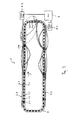
Fig. 1 schematisch vereinfacht eine Fördervorrichtung mit einer Reihe von mit Steuereinheiten versehenen Fördereinheiten in einer Draufsicht zeigt; und -
Fig. 2 schematisch vereinfacht eine Fördervorrichtung mit einer Reihe von mit Steuereinheiten versehenen Fördereinheiten in einer Draufsicht zeigt. -
Fig. 1 undFig. 2 zeigen lediglich einige wesentliche Elemente einer Fördervorrichtung 1, nämlich eine Reihe von Fördereinheiten 2.1-2.12, die sich entlang einer Förderstrecke 4, welche beispielsweise mit Führungsschienen 4.1, 4.2 versehen ist, bewegen. Ein gesteuerter Fahrantrieb und eine Führung mittels Lauf- und Führungsrollen entlang der Förderstrecke 4 sind aus dem Stand der Technik bekannt und nicht im Einzelnen dargestellt. Gleiches gilt für eine Verbindung benachbarter Fördereinheiten 2.1-2.12 mit einer Kupplung. - Jede Fördereinheit 2.1-2.12 weist ein Lastaufnahmemittel auf, das mittels eines Antriebs zum Aufnehmen oder Abgeben eines zu sortierenden oder transportierenden Stückguts antreibbar ist. Bei dem Lastaufnahmemittel kann es sich beispielsweise um eine seitlich kippbare Kippschale oder um einen quer zur Förderrichtung oder Fahrtrichtung 5 der Fördereinheiten 2.1-2.12 angeordneten Quergurt- oder Querbandförderer handeln, so dass ein aufgenommenes Stückgut an einer bestimmten Aufnahmeposition aufgenommen und an einer bestimmten Abgabeposition gezielt abgegeben werden kann. Die Energieversorgung von Fahrantrieb und Antrieb kann drahtlos erfolgen, beispielsweise induktiv, oder über entlang der Förderstrecke 4 verlegte oder in diese integrierte elektrische Kontakte oder Schleifkontakte.
- Jede Fördereinheit 2.1-2.12 ist mit einer Steuereinheit versehen, über die die Ansteuerung des Antriebs für das Lastaufnahmemittel erfolgt. Ferner ist jede Fördereinheit 2.1-2.12 mit einer Kommunikationsschnittstelle zum Empfangen von Steuerinformationen versehen. Die Kommunikationsschnittstellen sind in Master-Kommunikationsschnittstellen und Slave-Kommunikationsschnittstellen unterteilt, wobei jede Steuereinheit 2.1-2.12 eine Master-Kommunikationsschnittstelle oder eine Slave-Kommunikationsschnittstelle umfasst.
- Die Master-Kommunikationsschnittstellen der Fördereinheiten 2.1, 2.5, 2.10 umfassen jeweils eine drahtlose Kommunikationsschnittstelle zum Empfangen von Steuerinformationen unter Verwendung einer drahtlosen Kommunikationstechnologie. Die Master-Kommunikationsschnittstellen der Fördereinheiten 2.1, 2.5, 2.10 umfassen Funkmodule, deren Antennen an den langen geraden Abschnitten der Förderstrecke 4 in einen Leckwellenleiter, oder eine geschlitzte Mikrowellenführung (Schlitzwellenleiter) 6.1, 6.2 eintauchen. Die Master-Kommunikationsschnittstellen der Fördereinheiten 2.1, 2.10 empfangen Steuerinformationen von einer Steuervorrichtung 7, welche Steuerinformationen enthaltende Funksignale mittels mit Antennen versehener Zugangspunkte 8.1, 8.2, die mit der Steuervorrichtung 7 drahtgebunden oder drahtlos verbunden sind, in den Schlitzhohlleiter 6.1 einspeist.
- Die Slave-Kommunikationsschnittstellen umfassenden Fördereinheiten 2.2, 2.3, 2.6, 2.7, 2.11, 2.12 sind jeweils zwischen zwei Master-Kommunikationsschnittstellen umfassenden Fördereinheiten 2.1, 2.5, 2.10 angeordnet. Die Slave-Kommunikationsschnittstellen von Fördereinheiten 2.11, 2.12, die zwischen Fördereinheiten 2.5, 2.10 mit Master-Kommunikationsschnittstellen angeordnet sind, sind untereinander und mit den Master-Kommunikationsschnittstellen über einen Datenbus, bspw. einen Zweidrahtbus verbunden. Alternativ können die Slave-Kommunikationsschnittstellen von Fördereinheiten 2.11, 2.12 zwischen Fördereinheiten 2.5, 2.10 mit Master-Kommunikationsschnittstellen mit diesen sternförmig verkabelt sein.
- Dabei sind, wie in
Fig. 1 angedeutet, jeder Master-Kommunikationsschnittstelle eine Vielzahl von Slave-Kommunikationsschnittstellen zugeordnet, beispielsweise die Slave-Kommunikationsschnittstellen der auf eine Fördereinheit 2.10 mit Master-Kommunikationsschnittstelle nachfolgenden Fördereinheiten 2.13, 2.14. Da die Antenne des Funkmoduls der Master-Kommunikationsschnittstelle der Fördereinheit 2.5 in den Kurven und entlang der kurzen Seite der Förderstrecke 4 nicht in einen der Schlitzhohlleiter 6.1, 6.2 eintaucht, kann die Übertragung zwischen der Master-Kommunikationsschnittstelle der Fördereinheit 2.5 und der Steuervorrichtung 7 gestört oder unmöglich sein. Die Steuervorrichtung 7 kann bestimmen, wann die Master-Kommunikationsschnittstelle der Fördereinheit 2.5 nicht erreichbar ist, indem die Steuervorrichtung 7 die Position der Fördereinheiten 2.1-2.12 überwacht. Beispielsweise kann die Steuervorrichtung 7 die Fördereinheiten 2.1-2.12 regelmäßig zur Übermittlung von Positionsdaten auffordern. - Ist die Master-Kommunikationsschnittstelle der Fördereinheit 2.5 nicht erreichbar, werden entweder die der Master-Kommunikationsschnittstelle der Fördereinheit 2.5 zugeordneten Slave-Kommunikationsschnittstellen der Fördereinheiten 2.6, 2.7 der Master-Kommunikationsschnittstelle der Fördereinheit 2.10 zugeordnet, wie in
Fig. 1 angedeutet, oder es wird die Information zur drahtlos nicht erreichbaren Master-Kommunikationsschnittstelle der Fördereinheit 2.5 von der Master-Kommunikationsschnittstelle der Fördereinheit 2.10 oder 2.xx weitergeleitet (wie inFig. 2 angedeutet). Dabei wird die an die Master-Kommunikationsschnittstelle der Fördereinheit 2.5 bzw. die Slave-Kommunikations-schnittstellen der Fördereinheiten 2.6, 2.7 gerichtete Steuerinformationen von der Steuervorrichtung 7 an die Master-Kommunikationsschnittstelle der Fördereinheit 2.10 oder 2.xx gesendet, die ihrerseits die Steuerinformationen drahtgebunden an die Master-Kommunikationsschnittstelle der Fördereinheit 2.5 bzw. die Slave-Kommunikationsschnittstellen der Fördereinheiten 2.6, 2.7 weiterleitet. Auch eine Weiterleitung von 2.yy über 2.xx an 2.5 wäre denkbar, wenn beispielsweise die Master-Kommunikations-schnittstellen der Fördereinheiten 2.5 und 2.xx nicht erreichbar wären. - Werden die an die Slave-Kommunikationsschnittstellen der Steuereinheiten 2.6, 2.7 gerichteten Steuerinformationen an die Master-Kommunikationsschnittstelle der Fördereinheit 2.5 weitergeleitet, leitet diese die Steuerinformationen an die Slave-Kommunikationsschnittstellen der Fördereinheiten 2.6, 2.7 weiter. Während somit durch die Weiterleitung der Steuerinformationen von der erreichbaren Master-Kommunikationsschnittstelle der Fördereinheit 2.10 zu der Master-Kommunikationsschnittstelle der Fördereinheit 2.5 eine durch die ursprüngliche Zuordnung definierte Vorzugsrichtung des Informationsflusses beibehalten werden kann, wird diese durch die Neuzuordnung der Slave-Kommunikationsschnittstellen der Fördereinheiten 2.6, 2.7 zur Master-Kommunikationsschnittstelle der Fördereinheit 2.10 invertiert, d. h. die bevorzugte Kommunikationsrichtung kann, während die Master-Kommunikationsschnittstelle der Fördereinheit 2.5 nicht erreichbar ist, umgekehrt werden.
- Das Weiterleiten der Steuerinformationen von der erreichbaren Master-Kommunikationsschnittstelle zu der nicht erreichbaren Master-Kommunikationsschnittstelle bzw. direkt an die Slave-Kommunikationsschnittstellen muss nur solange aufrecht erhalten werden, solange der Empfang der nicht erreichbaren Master-Kommunikationsschnittstelle gestört ist. Entfällt der Grund des fehlenden Empfangs, beispielsweise weil die Fördereinheit 2.5 aus dem Bereich, in dem ein Empfang von Steuerinformationen unmöglich ist, herausbewegt wird, können die Steuerinformationen wieder (direkt) an die Master-Kommunikationsschnittstelle der Fördereinheit 2.5 gesendet werden, die diese dann in bevorzugter Kommunikationsrichtung an die zugeordneten Slave-Kommunikationsschnittstellen weiterleitet. Alternativ kann der veränderte Zustand solange beibehalten werden, bis die Master-Kommunikationsschnittstelle der Fördereinheit 2.10 bzw. eine andere Master-Kommunikationsschnittstelle nicht erreichbar ist und die Einrichtung einer neuen Weiterleitung bzw. eine Neuzordnung der entsprechenden Master-Kommunikationsschnittstelle zugeordneten Slave-Kommunikationsschnittstellen nötig wird.
-
- 1
- Fördervorrichtung
- 2.1-2.12
- Fördereinheiten
- 4
- Förderstrecke
- 4.1,4.2
- Führungsschienen
- 5
- Fahrtrichtung
- 6.1,6.2
- Schlitzhohlleiter
- 7
- Steuervorrichtung
- 8.1,8.2
- Zugangspunkte
Claims (10)
- Fördervorrichtung (1) mit einer Reihe von Fördereinheiten (2.1-2.12), die zur Bewegung entlang einer Förderstrecke (4) antreibbar sind, wobei jede Fördereinheit (2.1-2.12) einen Förderwagen, ein auf dem Förderwagen gehaltenes selektiv steuerbares Lastaufnahmemittel zum Aufnehmen und gezielten Abgeben eines Förderguts, eine Steuereinheit zum Ansteuern des Lastaufnahmemittels und eine Kommunikationsschnittstelle zum Empfangen von Steuerinformationen aufweist, dadurch gekennzeichnet, dass die Kommunikationsschnittstellen in Master-Kommunikationsschnittstellen und Slave- Kommunikationsschnittstellen unterteilt sind, wobei jede Master-Kommunikationsschnittstelle eine drahtlose Kommunikationsschnittstelle umfasst und wobei jede Master-Kommunikationsschnittstelle und jede Slave-Kommunikationsschnittstelle eine drahtgebundene Kommunikationsschnittstelle umfassen und jede Slave-Kommunikationsschnittstelle dazu eingerichtet ist, Steuerinformationen von einer zugeordneten Master-Kommunikationsschnittstelle über entsprechende drahtgebundene Kommunikationsschnittstellen zu empfangen.
- Fördervorrichtung (1) nach Anspruch 1, dadurch gekennzeichnet, dass die Fördervorrichtung (1) dazu eingerichtet ist, im Betrieb Steuerinformationen von einer ersten Master-Kommunikationsschnittstelle an eine zweite Master-Kommunikationsschnittstelle weiterzuleiten.
- Fördervorrichtung (1) nach Anspruch 2, ferner umfassend eine Steuervorrichtung (7), dadurch gekennzeichnet, dass die Steuervorrichtung (7) dazu eingerichtet ist, im Betrieb die Positionen der Reihe von Fördereinheiten zu überwachen und an die zweite Master-Kommunikationsschnittstelle adressierte Steuerinformationen an die erste Master-Kommunikationsschnittstelle weiterzuleiten, wenn die zweite Master-Kommunikationsschnittstelle in einem vorbestimmten Bereich ist.
- Fördervorrichtung (1) nach Anspruch 1, dadurch gekennzeichnet, dass die Fördervorrichtung (1) dazu eingerichtet ist, im Betrieb eine Zuordnung von Master-Kommunikationsschnittstellen und Slave-Kommunikationsschnittstellen dynamisch zu ändern.
- Fördervorrichtung (1) nach Anspruch 4, ferner umfassend eine Steuervorrichtung (7), dadurch gekennzeichnet, dass die Steuervorrichtung (7) dazu eingerichtet ist, im Betrieb die Positionen der Reihe von Fördereinheiten (2.1, 2.5, 2.10) zu überwachen und die Zuordnung der Master-Kommunikationsschnittstellen und Slave-Kommunikationsschnittstellen zu ändern, wenn eine der Master-Schnittstellen in einem vorbestimmten Bereich ist.
- Fördervorrichtung (1) nach Anspruch 3 oder 5, dadurch gekennzeichnet, dass die Steuervorrichtung (7) eine drahtlose Kommunikationsschnittstelle aufweist und dazu eingerichtet ist, die Steuerinformationen an die Master-Kommunikationsschnittstellen zu übertragen und wobei der vorbestimmte Bereich ein Bereich ist, in dem eine direkte drahtlose Übertragung der Steuerinformationen von der drahtlosen Kommunikationsschnittstelle der Steuervorrichtung (7) an eine Master-Kommunikationsschnittstelle einer in dem vorbestimmten Bereich befindlichen Fördereinheit (2.5) nicht möglich ist.
- Fördervorrichtung (1) nach einem der vorangehenden Ansprüche, dadurch gekennzeichnet, dass die Förderstrecke (4) eine Führungsbahn ist und die Förderwagen mit Rädern zum Abrollen auf der Führungsbahn versehen sind.
- Fördervorrichtung (1) nach einem der vorangehenden Ansprüche, dadurch gekennzeichnet, dass die Förderwagen Zug-artig miteinander verbunden sind und zwischen zwei Master-Kommunikationsschnittstellen eine Mehrzahl an Slave-Kommunikationsschnittstellen angeordnet ist.
- Fördervorrichtung (1) nach Anspruch 8, dadurch gekennzeichnet, dass die Mehrzahl an Slave-Kommunikationsschnittstellen einer Master-Kommunikationsschnittstelle zugeordnet ist.
- Fördervorrichtung (1) nach einem der vorangehenden Ansprüche, dadurch gekennzeichnet, dass jede Steuereinheit für die Steuerung eines Antriebs des Lastaufnahmemittels zum Abgeben eines geförderten Gegenstands in einer bestimmten Richtung eingerichtet ist.
Priority Applications (1)
| Application Number | Priority Date | Filing Date | Title |
|---|---|---|---|
| EP15003306.6A EP3170776B1 (de) | 2015-11-19 | 2015-11-19 | Fördervorrichtung mit steuereinheiten |
Applications Claiming Priority (1)
| Application Number | Priority Date | Filing Date | Title |
|---|---|---|---|
| EP15003306.6A EP3170776B1 (de) | 2015-11-19 | 2015-11-19 | Fördervorrichtung mit steuereinheiten |
Publications (2)
| Publication Number | Publication Date |
|---|---|
| EP3170776A1 true EP3170776A1 (de) | 2017-05-24 |
| EP3170776B1 EP3170776B1 (de) | 2020-12-30 |
Family
ID=54695434
Family Applications (1)
| Application Number | Title | Priority Date | Filing Date |
|---|---|---|---|
| EP15003306.6A Active EP3170776B1 (de) | 2015-11-19 | 2015-11-19 | Fördervorrichtung mit steuereinheiten |
Country Status (1)
| Country | Link |
|---|---|
| EP (1) | EP3170776B1 (de) |
Cited By (2)
| Publication number | Priority date | Publication date | Assignee | Title |
|---|---|---|---|---|
| CN112424096A (zh) * | 2018-07-13 | 2021-02-26 | 英特诺控股公司 | 具有至少两个传送滑架和在传送滑架中的至少一者上用于横向带式传送机的传动系制动器的传送装置 |
| EP4230553A3 (de) * | 2022-02-16 | 2023-10-18 | Günther Zimmer | Fördersystem einer fertigungszelle |
Citations (2)
| Publication number | Priority date | Publication date | Assignee | Title |
|---|---|---|---|---|
| US20040109745A1 (en) * | 2000-09-23 | 2004-06-10 | Wood John Nathan | Material sortation system |
| EP1627831A1 (de) * | 2004-08-17 | 2006-02-22 | Siemens Aktiengesellschaft | Sortier- und Verteilsystem sowie ein Verfahren zur Energie- und Datenübertragung |
-
2015
- 2015-11-19 EP EP15003306.6A patent/EP3170776B1/de active Active
Patent Citations (2)
| Publication number | Priority date | Publication date | Assignee | Title |
|---|---|---|---|---|
| US20040109745A1 (en) * | 2000-09-23 | 2004-06-10 | Wood John Nathan | Material sortation system |
| EP1627831A1 (de) * | 2004-08-17 | 2006-02-22 | Siemens Aktiengesellschaft | Sortier- und Verteilsystem sowie ein Verfahren zur Energie- und Datenübertragung |
Cited By (3)
| Publication number | Priority date | Publication date | Assignee | Title |
|---|---|---|---|---|
| CN112424096A (zh) * | 2018-07-13 | 2021-02-26 | 英特诺控股公司 | 具有至少两个传送滑架和在传送滑架中的至少一者上用于横向带式传送机的传动系制动器的传送装置 |
| US11745958B2 (en) | 2018-07-13 | 2023-09-05 | Interroll Holding Ag | Conveyor device with at least two conveyor carriages and a powertrain brake for a cross belt conveyor on at least one of the conveyor carriages |
| EP4230553A3 (de) * | 2022-02-16 | 2023-10-18 | Günther Zimmer | Fördersystem einer fertigungszelle |
Also Published As
| Publication number | Publication date |
|---|---|
| EP3170776B1 (de) | 2020-12-30 |
Similar Documents
| Publication | Publication Date | Title |
|---|---|---|
| EP3176111B1 (de) | Sortiervorrichtung für stückgut und verfahren | |
| EP3020614B1 (de) | Fördersystem zum fördern von gegenständen sowie steuerungsverfahren hierfür | |
| DE102007014876B4 (de) | Transportsystem | |
| DE69112719T2 (de) | Fördersystem in Modulbauweise. | |
| DE102006034395B4 (de) | Vorrichtung zum Transportieren von Gegenständen | |
| DE112018005017B4 (de) | Drahtlose steuerung eng beabstandeter maschinen | |
| EP0814994A1 (de) | Spurgeführte transporteinrichtung mit energie- und informationsübertragung | |
| DE60112592T2 (de) | Materialsortiersystem | |
| DE102011109531A1 (de) | Anlage und Verfahren zum Betreiben einer Anlage | |
| AT509949B1 (de) | Speicherlager | |
| DE69313020T2 (de) | Drahtloses, automatisiertes und rechnergesteuertes Lager- und Transportsystem | |
| DE102022004830A1 (de) | Verrfahren zum Transportieren von Gegenständen in einer technischen Anlage und technische Anlage | |
| EP3170776B1 (de) | Fördervorrichtung mit steuereinheiten | |
| EP3459781A2 (de) | Schienengebundenes transportsystem, schienensystem und schienenfahrzeug für ein schienengebundenes transportsystem | |
| DE60303478T2 (de) | Fördervorrichtung und Verfahren zum Fördern von Produkten | |
| EP3781460B1 (de) | Fahrerloses bodenfahrzeug zur förderung von lasten wie fahrzeugkarosserien oder/und fahrzeugteilen sowie verfahren zum transportieren einer solchen last | |
| CN107571009A (zh) | 组装生产线 | |
| EP1988038B1 (de) | Verfahren zum Abgeben und Aufnehmen von Werkstücken auf eine Arbeitsebene | |
| DE102012024580B4 (de) | Fördersystem zur Förderung von Objekten entlang einer Förderstrecke, wobei das Fördersystem ein Rollenförderer ist | |
| DE102008047755A1 (de) | Vorrichtung und Verfahren zur Steuerung von Elektrohängebahnen | |
| CN212197409U (zh) | 一种分拣物品的装置 | |
| EP4230553A2 (de) | Fördersystem einer fertigungszelle | |
| DE102022119120B3 (de) | Verfahren zum Betreiben eines Shuttle-Systems | |
| DE102013013018A1 (de) | Lagersystem mit einem Kettentrieb | |
| EP0554769B1 (de) | Transportsystem zum Transportieren von durch Kodiermittel kenntlich gemachtem Transportgut |
Legal Events
| Date | Code | Title | Description |
|---|---|---|---|
| PUAI | Public reference made under article 153(3) epc to a published international application that has entered the european phase |
Free format text: ORIGINAL CODE: 0009012 |
|
| STAA | Information on the status of an ep patent application or granted ep patent |
Free format text: STATUS: THE APPLICATION HAS BEEN PUBLISHED |
|
| AK | Designated contracting states |
Kind code of ref document: A1 Designated state(s): AL AT BE BG CH CY CZ DE DK EE ES FI FR GB GR HR HU IE IS IT LI LT LU LV MC MK MT NL NO PL PT RO RS SE SI SK SM TR |
|
| AX | Request for extension of the european patent |
Extension state: BA ME |
|
| STAA | Information on the status of an ep patent application or granted ep patent |
Free format text: STATUS: REQUEST FOR EXAMINATION WAS MADE |
|
| 17P | Request for examination filed |
Effective date: 20171120 |
|
| RBV | Designated contracting states (corrected) |
Designated state(s): AL AT BE BG CH CY CZ DE DK EE ES FI FR GB GR HR HU IE IS IT LI LT LU LV MC MK MT NL NO PL PT RO RS SE SI SK SM TR |
|
| RAP1 | Party data changed (applicant data changed or rights of an application transferred) |
Owner name: BEUMER GROUP GMBH & CO. KG |
|
| GRAP | Despatch of communication of intention to grant a patent |
Free format text: ORIGINAL CODE: EPIDOSNIGR1 |
|
| STAA | Information on the status of an ep patent application or granted ep patent |
Free format text: STATUS: GRANT OF PATENT IS INTENDED |
|
| INTG | Intention to grant announced |
Effective date: 20200728 |
|
| GRAS | Grant fee paid |
Free format text: ORIGINAL CODE: EPIDOSNIGR3 |
|
| GRAA | (expected) grant |
Free format text: ORIGINAL CODE: 0009210 |
|
| STAA | Information on the status of an ep patent application or granted ep patent |
Free format text: STATUS: THE PATENT HAS BEEN GRANTED |
|
| AK | Designated contracting states |
Kind code of ref document: B1 Designated state(s): AL AT BE BG CH CY CZ DE DK EE ES FI FR GB GR HR HU IE IS IT LI LT LU LV MC MK MT NL NO PL PT RO RS SE SI SK SM TR |
|
| REG | Reference to a national code |
Ref country code: GB Ref legal event code: FG4D Free format text: NOT ENGLISH |
|
| REG | Reference to a national code |
Ref country code: DE Ref legal event code: R096 Ref document number: 502015014062 Country of ref document: DE |
|
| REG | Reference to a national code |
Ref country code: AT Ref legal event code: REF Ref document number: 1349744 Country of ref document: AT Kind code of ref document: T Effective date: 20210115 |
|
| REG | Reference to a national code |
Ref country code: IE Ref legal event code: FG4D Free format text: LANGUAGE OF EP DOCUMENT: GERMAN |
|
| REG | Reference to a national code |
Ref country code: NL Ref legal event code: FP |
|
| PG25 | Lapsed in a contracting state [announced via postgrant information from national office to epo] |
Ref country code: NO Free format text: LAPSE BECAUSE OF FAILURE TO SUBMIT A TRANSLATION OF THE DESCRIPTION OR TO PAY THE FEE WITHIN THE PRESCRIBED TIME-LIMIT Effective date: 20210330 Ref country code: RS Free format text: LAPSE BECAUSE OF FAILURE TO SUBMIT A TRANSLATION OF THE DESCRIPTION OR TO PAY THE FEE WITHIN THE PRESCRIBED TIME-LIMIT Effective date: 20201230 Ref country code: FI Free format text: LAPSE BECAUSE OF FAILURE TO SUBMIT A TRANSLATION OF THE DESCRIPTION OR TO PAY THE FEE WITHIN THE PRESCRIBED TIME-LIMIT Effective date: 20201230 Ref country code: GR Free format text: LAPSE BECAUSE OF FAILURE TO SUBMIT A TRANSLATION OF THE DESCRIPTION OR TO PAY THE FEE WITHIN THE PRESCRIBED TIME-LIMIT Effective date: 20210331 |
|
| PG25 | Lapsed in a contracting state [announced via postgrant information from national office to epo] |
Ref country code: LV Free format text: LAPSE BECAUSE OF FAILURE TO SUBMIT A TRANSLATION OF THE DESCRIPTION OR TO PAY THE FEE WITHIN THE PRESCRIBED TIME-LIMIT Effective date: 20201230 Ref country code: SE Free format text: LAPSE BECAUSE OF FAILURE TO SUBMIT A TRANSLATION OF THE DESCRIPTION OR TO PAY THE FEE WITHIN THE PRESCRIBED TIME-LIMIT Effective date: 20201230 Ref country code: BG Free format text: LAPSE BECAUSE OF FAILURE TO SUBMIT A TRANSLATION OF THE DESCRIPTION OR TO PAY THE FEE WITHIN THE PRESCRIBED TIME-LIMIT Effective date: 20210330 |
|
| PG25 | Lapsed in a contracting state [announced via postgrant information from national office to epo] |
Ref country code: HR Free format text: LAPSE BECAUSE OF FAILURE TO SUBMIT A TRANSLATION OF THE DESCRIPTION OR TO PAY THE FEE WITHIN THE PRESCRIBED TIME-LIMIT Effective date: 20201230 |
|
| REG | Reference to a national code |
Ref country code: LT Ref legal event code: MG9D |
|
| PG25 | Lapsed in a contracting state [announced via postgrant information from national office to epo] |
Ref country code: CZ Free format text: LAPSE BECAUSE OF FAILURE TO SUBMIT A TRANSLATION OF THE DESCRIPTION OR TO PAY THE FEE WITHIN THE PRESCRIBED TIME-LIMIT Effective date: 20201230 Ref country code: EE Free format text: LAPSE BECAUSE OF FAILURE TO SUBMIT A TRANSLATION OF THE DESCRIPTION OR TO PAY THE FEE WITHIN THE PRESCRIBED TIME-LIMIT Effective date: 20201230 Ref country code: RO Free format text: LAPSE BECAUSE OF FAILURE TO SUBMIT A TRANSLATION OF THE DESCRIPTION OR TO PAY THE FEE WITHIN THE PRESCRIBED TIME-LIMIT Effective date: 20201230 Ref country code: PT Free format text: LAPSE BECAUSE OF FAILURE TO SUBMIT A TRANSLATION OF THE DESCRIPTION OR TO PAY THE FEE WITHIN THE PRESCRIBED TIME-LIMIT Effective date: 20210430 Ref country code: SK Free format text: LAPSE BECAUSE OF FAILURE TO SUBMIT A TRANSLATION OF THE DESCRIPTION OR TO PAY THE FEE WITHIN THE PRESCRIBED TIME-LIMIT Effective date: 20201230 Ref country code: LT Free format text: LAPSE BECAUSE OF FAILURE TO SUBMIT A TRANSLATION OF THE DESCRIPTION OR TO PAY THE FEE WITHIN THE PRESCRIBED TIME-LIMIT Effective date: 20201230 |
|
| PG25 | Lapsed in a contracting state [announced via postgrant information from national office to epo] |
Ref country code: PL Free format text: LAPSE BECAUSE OF FAILURE TO SUBMIT A TRANSLATION OF THE DESCRIPTION OR TO PAY THE FEE WITHIN THE PRESCRIBED TIME-LIMIT Effective date: 20201230 |
|
| PG25 | Lapsed in a contracting state [announced via postgrant information from national office to epo] |
Ref country code: IS Free format text: LAPSE BECAUSE OF FAILURE TO SUBMIT A TRANSLATION OF THE DESCRIPTION OR TO PAY THE FEE WITHIN THE PRESCRIBED TIME-LIMIT Effective date: 20210430 |
|
| REG | Reference to a national code |
Ref country code: DE Ref legal event code: R097 Ref document number: 502015014062 Country of ref document: DE |
|
| PG25 | Lapsed in a contracting state [announced via postgrant information from national office to epo] |
Ref country code: AL Free format text: LAPSE BECAUSE OF FAILURE TO SUBMIT A TRANSLATION OF THE DESCRIPTION OR TO PAY THE FEE WITHIN THE PRESCRIBED TIME-LIMIT Effective date: 20201230 |
|
| PLBE | No opposition filed within time limit |
Free format text: ORIGINAL CODE: 0009261 |
|
| STAA | Information on the status of an ep patent application or granted ep patent |
Free format text: STATUS: NO OPPOSITION FILED WITHIN TIME LIMIT |
|
| PG25 | Lapsed in a contracting state [announced via postgrant information from national office to epo] |
Ref country code: DK Free format text: LAPSE BECAUSE OF FAILURE TO SUBMIT A TRANSLATION OF THE DESCRIPTION OR TO PAY THE FEE WITHIN THE PRESCRIBED TIME-LIMIT Effective date: 20201230 |
|
| 26N | No opposition filed |
Effective date: 20211001 |
|
| PG25 | Lapsed in a contracting state [announced via postgrant information from national office to epo] |
Ref country code: ES Free format text: LAPSE BECAUSE OF FAILURE TO SUBMIT A TRANSLATION OF THE DESCRIPTION OR TO PAY THE FEE WITHIN THE PRESCRIBED TIME-LIMIT Effective date: 20201230 |
|
| PG25 | Lapsed in a contracting state [announced via postgrant information from national office to epo] |
Ref country code: SI Free format text: LAPSE BECAUSE OF FAILURE TO SUBMIT A TRANSLATION OF THE DESCRIPTION OR TO PAY THE FEE WITHIN THE PRESCRIBED TIME-LIMIT Effective date: 20201230 |
|
| PG25 | Lapsed in a contracting state [announced via postgrant information from national office to epo] |
Ref country code: IS Free format text: LAPSE BECAUSE OF FAILURE TO SUBMIT A TRANSLATION OF THE DESCRIPTION OR TO PAY THE FEE WITHIN THE PRESCRIBED TIME-LIMIT Effective date: 20210430 |
|
| PG25 | Lapsed in a contracting state [announced via postgrant information from national office to epo] |
Ref country code: MC Free format text: LAPSE BECAUSE OF FAILURE TO SUBMIT A TRANSLATION OF THE DESCRIPTION OR TO PAY THE FEE WITHIN THE PRESCRIBED TIME-LIMIT Effective date: 20201230 |
|
| REG | Reference to a national code |
Ref country code: CH Ref legal event code: PL |
|
| PG25 | Lapsed in a contracting state [announced via postgrant information from national office to epo] |
Ref country code: LU Free format text: LAPSE BECAUSE OF NON-PAYMENT OF DUE FEES Effective date: 20211119 Ref country code: BE Free format text: LAPSE BECAUSE OF NON-PAYMENT OF DUE FEES Effective date: 20211130 |
|
| REG | Reference to a national code |
Ref country code: BE Ref legal event code: MM Effective date: 20211130 |
|
| PG25 | Lapsed in a contracting state [announced via postgrant information from national office to epo] |
Ref country code: LI Free format text: LAPSE BECAUSE OF NON-PAYMENT OF DUE FEES Effective date: 20211130 Ref country code: CH Free format text: LAPSE BECAUSE OF NON-PAYMENT OF DUE FEES Effective date: 20211130 |
|
| PG25 | Lapsed in a contracting state [announced via postgrant information from national office to epo] |
Ref country code: IE Free format text: LAPSE BECAUSE OF NON-PAYMENT OF DUE FEES Effective date: 20211119 |
|
| REG | Reference to a national code |
Ref country code: AT Ref legal event code: MM01 Ref document number: 1349744 Country of ref document: AT Kind code of ref document: T Effective date: 20211119 |
|
| PG25 | Lapsed in a contracting state [announced via postgrant information from national office to epo] |
Ref country code: AT Free format text: LAPSE BECAUSE OF NON-PAYMENT OF DUE FEES Effective date: 20211119 |
|
| PG25 | Lapsed in a contracting state [announced via postgrant information from national office to epo] |
Ref country code: HU Free format text: LAPSE BECAUSE OF FAILURE TO SUBMIT A TRANSLATION OF THE DESCRIPTION OR TO PAY THE FEE WITHIN THE PRESCRIBED TIME-LIMIT; INVALID AB INITIO Effective date: 20151119 |
|
| P01 | Opt-out of the competence of the unified patent court (upc) registered |
Effective date: 20230411 |
|
| PG25 | Lapsed in a contracting state [announced via postgrant information from national office to epo] |
Ref country code: CY Free format text: LAPSE BECAUSE OF FAILURE TO SUBMIT A TRANSLATION OF THE DESCRIPTION OR TO PAY THE FEE WITHIN THE PRESCRIBED TIME-LIMIT Effective date: 20201230 |
|
| PG25 | Lapsed in a contracting state [announced via postgrant information from national office to epo] |
Ref country code: SM Free format text: LAPSE BECAUSE OF FAILURE TO SUBMIT A TRANSLATION OF THE DESCRIPTION OR TO PAY THE FEE WITHIN THE PRESCRIBED TIME-LIMIT Effective date: 20201230 |
|
| PG25 | Lapsed in a contracting state [announced via postgrant information from national office to epo] |
Ref country code: MK Free format text: LAPSE BECAUSE OF FAILURE TO SUBMIT A TRANSLATION OF THE DESCRIPTION OR TO PAY THE FEE WITHIN THE PRESCRIBED TIME-LIMIT Effective date: 20201230 |
|
| PG25 | Lapsed in a contracting state [announced via postgrant information from national office to epo] |
Ref country code: TR Free format text: LAPSE BECAUSE OF FAILURE TO SUBMIT A TRANSLATION OF THE DESCRIPTION OR TO PAY THE FEE WITHIN THE PRESCRIBED TIME-LIMIT Effective date: 20201230 |
|
| PG25 | Lapsed in a contracting state [announced via postgrant information from national office to epo] |
Ref country code: MT Free format text: LAPSE BECAUSE OF FAILURE TO SUBMIT A TRANSLATION OF THE DESCRIPTION OR TO PAY THE FEE WITHIN THE PRESCRIBED TIME-LIMIT Effective date: 20201230 |
|
| PGFP | Annual fee paid to national office [announced via postgrant information from national office to epo] |
Ref country code: NL Payment date: 20251119 Year of fee payment: 11 |
|
| PGFP | Annual fee paid to national office [announced via postgrant information from national office to epo] |
Ref country code: DE Payment date: 20251118 Year of fee payment: 11 |
|
| PGFP | Annual fee paid to national office [announced via postgrant information from national office to epo] |
Ref country code: GB Payment date: 20251120 Year of fee payment: 11 |
|
| PGFP | Annual fee paid to national office [announced via postgrant information from national office to epo] |
Ref country code: IT Payment date: 20251128 Year of fee payment: 11 |
|
| PGFP | Annual fee paid to national office [announced via postgrant information from national office to epo] |
Ref country code: FR Payment date: 20251120 Year of fee payment: 11 |