EP3170707B1 - Kappe auf einem anschlussstück für einen scheibenwischer eines kraftfahrzeugs - Google Patents
Kappe auf einem anschlussstück für einen scheibenwischer eines kraftfahrzeugs Download PDFInfo
- Publication number
- EP3170707B1 EP3170707B1 EP16195295.7A EP16195295A EP3170707B1 EP 3170707 B1 EP3170707 B1 EP 3170707B1 EP 16195295 A EP16195295 A EP 16195295A EP 3170707 B1 EP3170707 B1 EP 3170707B1
- Authority
- EP
- European Patent Office
- Prior art keywords
- cover
- connector
- shaft
- longitudinal
- cap
- Prior art date
- Legal status (The legal status is an assumption and is not a legal conclusion. Google has not performed a legal analysis and makes no representation as to the accuracy of the status listed.)
- Active
Links
- 238000000034 method Methods 0.000 claims description 7
- 239000011521 glass Substances 0.000 description 6
- 239000000463 material Substances 0.000 description 6
- XLYOFNOQVPJJNP-UHFFFAOYSA-N water Substances O XLYOFNOQVPJJNP-UHFFFAOYSA-N 0.000 description 3
- XECAHXYUAAWDEL-UHFFFAOYSA-N acrylonitrile butadiene styrene Chemical compound C=CC=C.C=CC#N.C=CC1=CC=CC=C1 XECAHXYUAAWDEL-UHFFFAOYSA-N 0.000 description 2
- 229920000122 acrylonitrile butadiene styrene Polymers 0.000 description 2
- 239000004676 acrylonitrile butadiene styrene Substances 0.000 description 2
- 244000245420 ail Species 0.000 description 2
- 239000000203 mixture Substances 0.000 description 2
- 238000000465 moulding Methods 0.000 description 2
- 229920000642 polymer Polymers 0.000 description 2
- 229920006324 polyoxymethylene Polymers 0.000 description 2
- 238000007599 discharging Methods 0.000 description 1
- 239000013013 elastic material Substances 0.000 description 1
- 238000003780 insertion Methods 0.000 description 1
- 230000037431 insertion Effects 0.000 description 1
- 238000009434 installation Methods 0.000 description 1
- 239000007788 liquid Substances 0.000 description 1
- 238000012423 maintenance Methods 0.000 description 1
- 239000002184 metal Substances 0.000 description 1
- 229920000515 polycarbonate Polymers 0.000 description 1
- 239000004417 polycarbonate Substances 0.000 description 1
- 239000002861 polymer material Substances 0.000 description 1
- -1 polyoxymethylenes Polymers 0.000 description 1
- 230000003014 reinforcing effect Effects 0.000 description 1
- 239000002689 soil Substances 0.000 description 1
- 238000010408 sweeping Methods 0.000 description 1
Images


Classifications
-
- B—PERFORMING OPERATIONS; TRANSPORTING
- B60—VEHICLES IN GENERAL
- B60S—SERVICING, CLEANING, REPAIRING, SUPPORTING, LIFTING, OR MANOEUVRING OF VEHICLES, NOT OTHERWISE PROVIDED FOR
- B60S1/00—Cleaning of vehicles
- B60S1/02—Cleaning windscreens, windows or optical devices
- B60S1/04—Wipers or the like, e.g. scrapers
- B60S1/32—Wipers or the like, e.g. scrapers characterised by constructional features of wiper blade arms or blades
- B60S1/38—Wiper blades
- B60S1/3848—Flat-type wiper blade, i.e. without harness
- B60S1/3849—Connectors therefor; Connection to wiper arm; Attached to blade
- B60S1/3851—Mounting of connector to blade assembly
-
- B—PERFORMING OPERATIONS; TRANSPORTING
- B60—VEHICLES IN GENERAL
- B60S—SERVICING, CLEANING, REPAIRING, SUPPORTING, LIFTING, OR MANOEUVRING OF VEHICLES, NOT OTHERWISE PROVIDED FOR
- B60S1/00—Cleaning of vehicles
- B60S1/02—Cleaning windscreens, windows or optical devices
- B60S1/04—Wipers or the like, e.g. scrapers
- B60S1/32—Wipers or the like, e.g. scrapers characterised by constructional features of wiper blade arms or blades
- B60S1/34—Wiper arms; Mountings therefor
- B60S1/3425—Constructional aspects of the arm
- B60S1/3443—Wiper shafts
-
- B—PERFORMING OPERATIONS; TRANSPORTING
- B60—VEHICLES IN GENERAL
- B60S—SERVICING, CLEANING, REPAIRING, SUPPORTING, LIFTING, OR MANOEUVRING OF VEHICLES, NOT OTHERWISE PROVIDED FOR
- B60S1/00—Cleaning of vehicles
- B60S1/02—Cleaning windscreens, windows or optical devices
- B60S1/04—Wipers or the like, e.g. scrapers
- B60S1/32—Wipers or the like, e.g. scrapers characterised by constructional features of wiper blade arms or blades
- B60S1/38—Wiper blades
- B60S1/3848—Flat-type wiper blade, i.e. without harness
- B60S1/3849—Connectors therefor; Connection to wiper arm; Attached to blade
-
- B—PERFORMING OPERATIONS; TRANSPORTING
- B60—VEHICLES IN GENERAL
- B60S—SERVICING, CLEANING, REPAIRING, SUPPORTING, LIFTING, OR MANOEUVRING OF VEHICLES, NOT OTHERWISE PROVIDED FOR
- B60S1/00—Cleaning of vehicles
- B60S1/02—Cleaning windscreens, windows or optical devices
- B60S1/04—Wipers or the like, e.g. scrapers
- B60S1/32—Wipers or the like, e.g. scrapers characterised by constructional features of wiper blade arms or blades
- B60S1/40—Connections between blades and arms
- B60S1/4038—Connections between blades and arms for arms provided with a channel-shaped end
- B60S1/4041—Connections between blades and arms for arms provided with a channel-shaped end the channel-shaped end comprising a pivot pin mounted between the side walls
-
- B—PERFORMING OPERATIONS; TRANSPORTING
- B60—VEHICLES IN GENERAL
- B60S—SERVICING, CLEANING, REPAIRING, SUPPORTING, LIFTING, OR MANOEUVRING OF VEHICLES, NOT OTHERWISE PROVIDED FOR
- B60S1/00—Cleaning of vehicles
- B60S1/02—Cleaning windscreens, windows or optical devices
- B60S1/04—Wipers or the like, e.g. scrapers
- B60S1/32—Wipers or the like, e.g. scrapers characterised by constructional features of wiper blade arms or blades
- B60S1/40—Connections between blades and arms
- B60S1/4038—Connections between blades and arms for arms provided with a channel-shaped end
- B60S1/4045—Connections between blades and arms for arms provided with a channel-shaped end comprising a detachable intermediate element mounted on the channel-shaped end
- B60S1/4048—Connections between blades and arms for arms provided with a channel-shaped end comprising a detachable intermediate element mounted on the channel-shaped end the element being provided with retention means co-operating with the channel-shaped end of the arm
-
- B—PERFORMING OPERATIONS; TRANSPORTING
- B60—VEHICLES IN GENERAL
- B60S—SERVICING, CLEANING, REPAIRING, SUPPORTING, LIFTING, OR MANOEUVRING OF VEHICLES, NOT OTHERWISE PROVIDED FOR
- B60S1/00—Cleaning of vehicles
- B60S1/02—Cleaning windscreens, windows or optical devices
- B60S1/04—Wipers or the like, e.g. scrapers
- B60S1/32—Wipers or the like, e.g. scrapers characterised by constructional features of wiper blade arms or blades
- B60S1/40—Connections between blades and arms
- B60S1/4067—Connections between blades and arms for arms provided with a side pin
- B60S1/4074—Connections between blades and arms for arms provided with a side pin with means provided on the blade for locking the side pin
-
- B—PERFORMING OPERATIONS; TRANSPORTING
- B60—VEHICLES IN GENERAL
- B60S—SERVICING, CLEANING, REPAIRING, SUPPORTING, LIFTING, OR MANOEUVRING OF VEHICLES, NOT OTHERWISE PROVIDED FOR
- B60S1/00—Cleaning of vehicles
- B60S1/02—Cleaning windscreens, windows or optical devices
- B60S1/04—Wipers or the like, e.g. scrapers
- B60S1/32—Wipers or the like, e.g. scrapers characterised by constructional features of wiper blade arms or blades
- B60S1/38—Wiper blades
- B60S2001/3898—Wiper blades method for manufacturing wiper blades
-
- B—PERFORMING OPERATIONS; TRANSPORTING
- B60—VEHICLES IN GENERAL
- B60S—SERVICING, CLEANING, REPAIRING, SUPPORTING, LIFTING, OR MANOEUVRING OF VEHICLES, NOT OTHERWISE PROVIDED FOR
- B60S1/00—Cleaning of vehicles
- B60S1/02—Cleaning windscreens, windows or optical devices
- B60S1/04—Wipers or the like, e.g. scrapers
- B60S1/32—Wipers or the like, e.g. scrapers characterised by constructional features of wiper blade arms or blades
- B60S1/40—Connections between blades and arms
- B60S1/4038—Connections between blades and arms for arms provided with a channel-shaped end
- B60S2001/4061—Connections between blades and arms for arms provided with a channel-shaped end covered by a removable cover mounted on the blade
Definitions
- the present invention relates to wiper systems for motor vehicles, and more particularly relates to an assembly device used to connect a wiper blade to a drive arm of the latter.
- Wiper systems for motor vehicles are designed to remove, by sweeping, the liquids and dirt that can disturb the driver's vision of the environment.
- These windscreen wipers generally comprise a drive arm that moves angularly about an axis of rotation, and an elongated wiper blade equipped with a scraper blade made of an elastic material. By rubbing against a glazed surface, front or rear, of the motor vehicle, the scraper blade sweeps the water and a number of soils, and evacuates them outside the field of vision of the driver.
- the wiper blade is attached to the drive arm by an assembly device which comprises at least one connector mounted integral with the wiper blade.
- an adapter adapted to be assembled with the wiper blade connector, is mounted on an end piece of the drive arm.
- This first mode of connection is commonly used for windscreen wipers for the glass surfaces located at the front of the motor vehicle (windshield).
- the connector is connected to a shaft integral with the drive arm. This second mode of connection is commonly found in wipers for glass surfaces located at the rear of the vehicle (rear window).
- the cap comprises a light for receiving the shaft and for allowing the translational movement of the cap.
- the light is shaped into a bend having a first portion for introducing the shaft into the interior of the light and a second part to allow the translation of the cap on the shaft and the connector, the first part being arranged orthogonally in the second part.
- the object of the present invention is to improve this situation by proposing a cap whose implementation on a shaft of a driving arm is fast, a mechanical connection between the cap and / or the driving arm and / or a connector being simple to implement, robust, efficient and durable.
- the invention relates to a cap for locking a shaft integral with a drive arm and a connector carrying a wiper blade, the cap extending along a longitudinal main axis and having minus two longitudinal flanks, each longitudinal flank being provided with a through opening delimited at a first longitudinal end by a bottom and at a second longitudinal end by an opening for receiving the shaft.
- said open is formed vis-à-vis said bottom.
- the emerging lumen is rectilinear at least between a bottom and an opening defining the emerging lumen. Note that the rectilinear direction that follows the emerging light extends along a longitudinal axis of the cap. This avoids the elbow conformation of the light of the prior art and assembly of the cap on the arm is facilitated.
- the invention also relates to an assembly formed by the connector provided with at least one bearing for receiving a shaft, by the shaft fitted to a drive arm and by such a cap.
- the invention further relates to a wiper blade equipped with a cap as described herein.
- the invention also relates to a wiper system comprising a drive arm provided with a shaft and such a wiper blade.
- the names longitudinal, lateral, transverse, vertical, above, below, refer to the orientation of a wiper blade 1 shown in FIG. figure 1 .
- a longitudinal direction corresponds to the main axis of the wiper blade 1 according to which the latter extends. This main axis is parallel to a longitudinal axis X along which extends the cap 20 object of the invention.
- a transverse direction corresponds to that of a transverse axis Y which is perpendicular to the longitudinal axis X of the cap 20 and perpendicular to an axis of rotation A r of a drive arm 2 constituting a wiper system 3
- a vertical direction, parallel to that of a vertical axis Z, and the upper or lower denominations relate to orientations parallel to the axis of rotation A r of the drive arm 2 of the wiper system 3, the denomination lower containing the plane of the windshield.
- the directions mentioned above are illustrated in an orthonormal Oxyz coordinate system shown in the figures.
- the axis Ox represents the longitudinal direction
- the axis Oy represents the transverse direction
- the axis Oz represents the vertical direction.
- a motor vehicle is commonly equipped with the wiper system 3 for discharging water and / or dirt present on a glass surface, including a rear window of the motor vehicle.
- the wiper system 3 comprises a drive arm 2 which is adapted to perform an angular back and forth movement along and above the glass surface.
- the glazed surface is indifferently a front windshield or a rear window equipping the motor vehicle.
- the wiper system 3 also comprises a wiper blade 1 which extends along a main axis, said longitudinal axis parallel to the axis Ox.
- the wiper blade 1 comprises at least one air deflector 4 and a scraper blade 5.
- the air deflector 4 is designed to transform a pressure applied by a flow of air flowing along the glass surface into a force supporting the wiper blade 1 against the glazed surface of the motor vehicle.
- the scraper blade 5 is the part of the wiper blade 1 in direct contact with the glass surface to evacuate the water and / or dirt present on the latter.
- the air deflector 4 and the scraper blade 5 form a semi-rigid assembly 6 which is carried by a connection device 7, interposed between the drive arm 2 and the semi-rigid assembly 6.
- connection device 7 provides a mechanical connection between the drive arm 2 and the wiper blade 1 and thus makes it possible to separate the wiper blade 1 from the drive arm 2, with a view to replacing the wiper blade. wiping 1.
- the connecting device 7 comprises for example a connector 8 shown in a longitudinal longitudinal section, along the longitudinal axis Ox of the wiper blade.
- the connector 8 comprises a base 9, which extends in the longitudinal and transverse directions, and a body 10 which extends above the base 9, substantially in the vertical direction.
- the connector 8 taken as a whole, has a first plane of symmetry P 1 , longitudinal and vertical, parallel to the Oxz plane of the orthonormal coordinate system defined above, and substantially median in the direction cross.
- the connector 8 is made by molding a polymer material, for example a material of the family of polyoxymethylenes, known by the acronym POM, or by molding a mixture of materials.
- polymers for example a mixture of polymers of the family of polycarbonates and the family Acrylonitrile Butadiene Styrene, known by the acronym ABS.
- Other materials known to those skilled in the art such as PBT 30GF can also be used.
- the base 9 comprises means for securing the connector 8 to the wiper blade 1.
- These securing means take the form of a first and a second groove 11 formed in the lower lateral parts of the base 9, which each delimits, in the lower lateral portion of this base 9, a hook 12 adapted to engage on the wiper blade 1. Only a groove 11 is shown on the figure 1 , the second groove being formed on the symmetrical portion of the base 9 relative to the first vertical plane of symmetry P 1 of the connector 8.
- the body 10, advantageously made of material with the base 9, extends above the latter in the vertical direction.
- the body 10 has a dimension in the transverse direction substantially less than the transverse dimension of the base 9, and a longitudinal dimension substantially equal to or greater than the longitudinal dimension of the base 9.
- the longitudinal dimension of the body 10 is greater than that of the base 9, and the connector 8 has a second plane of symmetry P 2 , transverse and vertical, parallel to the plane Oyz of the orthonormal reference defined above and substantially median along the longitudinal axis Ox.
- the body 10 comprises first and second lateral flanks 13, substantially vertical. Only a first lateral flank 13 is represented on the figure 2 , the second lateral flank being provided on the symmetrical portion of the base 9 relative to the first plane of symmetry P 1 of the connector 8.
- Each of these lateral flanks 13 is substantially plane, of small thickness in the transverse direction, and the distance between the external faces of these two lateral flanks 13 represents the dimension, in the transverse direction, of the body 10 of the connector 8.
- the first and second lateral flanks 13 thus delimit, between them, an interior volume of the connector 8.
- the first and second lateral flanks 13 are interconnected by a set of ribs 14a, 14b, which play in particular a reinforcing role of the body 10.
- the connector 8 comprises a pair of external ribs 14a and a couple of internal ribs 14b.
- the external ribs 14a on the one hand and the internal ribs 14b on the other hand are arranged symmetrically with respect to a transverse median plane of the connector, this median plane being parallel to the second plane of symmetry P 2 .
- the connector 8 comprises a first external groove 14a, a first internal groove 14b, a second internal groove 14a and a second external groove 14b.
- each of the first and second lateral flanks 13 has substantially, viewed from the side, a profile such that the upper surface of each of these lateral flanks 13, at its central portion in the longitudinal direction of the connector 8, forms a downward slope in the direction of each of their longitudinal ends.
- This shape makes it possible both to lighten the connector 8, and to facilitate its assembly with a cap according to the invention whose description is forthcoming or with the drive arm 2.
- a bearing 15 for receiving a shaft 2a secured to the drive arm 2 of the wiper system 3.
- the connector 8 is intended to be connected to the arm 2a when the a first step of an assembly process of the invention which is described below.
- a first landing stage 15 is thus formed in the first lateral flank 13, and a second reception stage can be formed in the second lateral flank.
- Each of the receiving bearings 15 has a substantially cylindrical shape and is through, that is to say, it extends transversely over the entire thickness of each of the lateral flanks 13.
- the inside diameter of each of the receiving bearings 15 is defined with respect to an average diameter of the shaft 2a integral with the drive arm 2 to which the connector 8 is intended to be connected.
- the centers of the two receiving bearings 15 respectively arranged in the first lateral flank 13 and in the second lateral flank are aligned along the transverse axis Y parallel to the direction of the axis Oy of the orthonormal frame defined above.
- the transverse axis Y materializes the axis of rotation of the wiper blade 1 with respect to the drive arm 2, once the shaft 2a is received inside the receiving bearings 15 of the connector 8.
- each of the receiving bearings 15 is placed substantially, in the longitudinal direction, in the central zone of the corresponding lateral flank.
- the transverse axis Y in which the centers of these receiving bearings 15 are aligned is therefore included inside the second plane of symmetry P 2 , transverse vertical, of the connector 8.
- the vertical direction, each of the levels of reception 15 advantageously extends substantially in the central zone of the body 10 of the connector 8.
- Each of these receiving bearings 15 is thus arranged on one or the other of the first or second lateral flanks 13, so that, d on the one hand, material of the lateral flank 13 corresponding above the landing bearing 15 remains, and in such a way that, on the other hand, material of the side flank 13 corresponding below said landing remains. 15, between its lowest point and the upper face of the base 9 of the connector 8.
- each inlet opening 16 is formed to the right of each of these receiving bearings 15, above them.
- the longitudinal dimension of each of the inlet openings 16 is smaller than the inside diameter of the receiving bearing 15 to which the inlet opening 16 gives access, and in which the inlet opening 16 opens.
- each inlet opening 16 forms an access cone to the corresponding receiving bearing 15.
- a first inlet opening 16 thus forms an access cone to the first receiving bearing 15 arranged in the first lateral flank 13, and a second inlet opening forms an access cone to the second receiving bearing arranged in the second lateral flank.
- the body 10 of the connector 8 further comprises, within the interior volume delimited by the first and second lateral flanks 13, a guide cheek 18 which extends substantially longitudinally and vertically, from the upper face of the base 9.
- the guide cheek 18 is placed, in the transverse direction, substantially in the middle part of the interior volume delimited by the two lateral flanks 13. It thus extends here substantially in the foreground. of symmetry P 1 , longitudinal vertical, of the connector 8.
- the guide cheek 18 is also advantageously placed in a substantially central position in the longitudinal direction of the connector 8.
- the profile of the upper surface of the guide cheek 18 is substantially similar to that of at least one of the first and / or Second lateral flanks 13.
- the dimension of the guide flange 18 in the vertical direction is, however, less than that of each of the lateral flanks 13, measured at their central portion along the longitudinal axis. Ox.
- a guide notch 19 is formed in the upper part of the guide cheek 18.
- This guide notch 19 opens to the upper surface of the guide cheek 18.
- the notch of guide 19 is arranged in such a way that it forms, in its lower part, substantially a half-cylinder centered on the transverse axis Y, and whose diameter is greater than that of said receiving bearings 15.
- this half-cylindrical portion extends vertically, towards the upper surface of the guide cheek 18, on a longitudinal dimension substantially equal to its diameter.
- the guiding notch 19 may present, in the direction of the upper surface of the guide cheek 18, a slight flare.
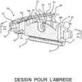
- FIG. 3 there is shown a cap 20 whose function is to lock and protect the connector 8 on the drive arm 2, and thus participate in the pivot connection that takes place between the wiper blade and the drive arm.
- the cap 20 extends along its length along a longitudinal axis X which, when the cap 20 is mounted on the wiper blade, is parallel to the main axis of the wiper blade 1.
- the cap 20 comprises a cover 21 formed by a cover 22 bordered by two lateral wings 23.
- the lateral wings 23 are formed parallel to each other and parallel to the longitudinal axis X and extend substantially within a third plane of symmetry P 3 .
- the cover 22 extends inside a plane orthogonal to the third plane of symmetry P 3 and to a fourth plane of symmetry P 4 .
- the cover 21 is shaped as a "U" whose base is formed by the cover 22 and the branches are formed by the lateral wings 23.
- the cover 21 delimits between the cover 22 and the lateral wings 23 an internal volume 24 which houses at least two longitudinal flanks 25 parallel to each other and substantially parallel to the lateral flanges 23.
- a distance measured in a transverse direction separates each longitudinal flank 25.
- another distance measured in this transverse direction separates a lateral flange 23 from the adjacent longitudinal flank.
- This other distance provides a space 32 which is intended to receive an end portion of the drive arm, in particular an end portion whose section forms a "U".
- the longitudinal flanks 25 are secured to an inner face of the cover 22 and a flap 26.
- the flap 26 extends inside the internal volume 24 being integral with a transverse wall 27 which is formed of the 23. This transverse wall 27 thus forms an end longitudinal wall of the cap 20.
- the flap 26 is formed in a plane which is substantially orthogonal to the third plane of symmetry P 3 and the fourth plane of symmetry P 4 .
- Each longitudinal flank 25 is terminated by a vertical edge 28 which is disposed opposite the transverse wall 27, with respect to the longitudinal flank 25.
- Each vertical edge 28 extends generally parallel to the vertical axis Z.
- Each longitudinal flank 25 is provided with a through opening 29 which extends along the longitudinal axis X of the cap.
- the opening lumen is provided to receive the shaft 2a of the drive arm 2.
- This light 29 takes the form of a cutout formed in the longitudinal flank concerned. It is open in the sense that it opens towards the external environment of the cap 20.
- the emerging lumen 29 is rectilinear and extends for example orthogonally to the vertical edge 28.
- the rectilinear character of the light is recognizable in that this light takes an oblong shape and extends in a single linear direction.
- This emerging lumen 29 is thus delimited at a first longitudinal end by an opening 29c, and at a second longitudinal end, by a bottom 29e. The latter is formed by a slice of the longitudinal flank 25 which delimits the emerging lumen 29.
- the emerging lumen 29 comprises a first portion 29a which is shaped as a parallelogram and a second portion 29b, adjacent to the first portion 29a, which is shaped in a semicircle.
- the first portion 29a is terminated by the opening 29c which is formed at the vertical edge 28.
- the first portion 29a and the second portion 29b are formed in the extension of one another, one having a rectangular shape while the other has a semicircle shape.
- the cap 20, in particular the flap 26, is provided with a tongue 30 which extends in the extension of the flap 26 and whose end is equipped with a transverse flange 31.
- a transverse flange 31 forms a tooth intended for engage on an edge of the connector.
- the tongue 30 is of a flat conformation and a thickness, taken along the vertical axis Z, which gives it a certain flexibility. In other words, the tongue 30 is tilting on the flap 26.
- the transverse flange 31 is of a thickness, taken along the vertical axis Z, which is greater than that of the tongue 30. In other words, the transverse flange 31 emerges at above the tongue 30, that is to say towards the internal volume 24.
- the through opening 29 and the transverse flange 31 form a fastening means 29, 31 of the cap 20 on a device consisting of the shaft 2a and the connector 8.
- the transverse flange 31 is engaged on one of the ribs 14a formed on the connector 8, preferably one of the two internal ribs. It will be noted moreover that the cap 20 can be installed at one or other of the longitudinal ends of the connector 8, the transverse flange 31 engaging the corresponding rib 14a.
- the securing means participates in a means for locking the wiper blade 1 to the drive arm 2 from the implementation of the assembly method of the present invention which comprises a plurality of successive steps.
- the pivoting attachment of the wiper blade on the shaft drive arm 2a is operated by the cooperation of the shaft 2a in the at least one receiving bearing 15 formed in the connector 8.
- a first step of the assembly process is to assemble the connector 8 and the shaft 2a of the drive arm 2, from a recess of the shaft 2a inside the receiving bearings 15, and advantageously to the guiding notch 19 of the connector 8. At this stage, the pivotal connection between the wiper blade and the drive arm is complete.
- a second step of the assembly process consists of putting the shaft 2a in position inside the opening lumen or openings 29.
- the cap 20 is approached from the connector 8 and the through-lumens 29 are inserted on the 2a, following a translational movement along the longitudinal axis X of the cap 20.
- a third step of the assembly process is to continue the translation of the cap 20 on the connector 8 until the transverse flange 31 engages an inner face of the outer rib 14a of the connector 8. Once abutted, the cap 20 immobilizes an assembly 2a, 8, 20 formed by the shaft 2a, the connector 8 and the cap 20.
Landscapes
- Engineering & Computer Science (AREA)
- Mechanical Engineering (AREA)
- Pivots And Pivotal Connections (AREA)
- Ink Jet (AREA)
- Lock And Its Accessories (AREA)
- Connector Housings Or Holding Contact Members (AREA)
Claims (15)
- Kappe (20), welche dazu bestimmt ist, eine Welle (2a), die mit einem Antriebsarm fest verbunden ist, und ein Anschlussstück (8), das ein Scheibenwischerblatt (1) trägt, zu verriegeln, wobei sich die Kappe (20) entlang einer Längshauptachse (X) erstreckt und wenigstens zwei Längsflanken (25) aufweist, wobei jede Längsflanke (25) mit einem in den Rand mündenden Schlitz (29) versehen ist, der an einem ersten Längsende von einem Boden (29e) und an einem zweiten Längsende von einer Öffnung (29c) für die Aufnahme der Welle (2a) begrenzt wird, wobei die Kappe (20) dadurch gekennzeichnet ist, dass die Öffnung (29c) gegenüber dem Boden (29e) ausgebildet ist.
- Kappe (20) nach Anspruch 1, wobei der Umfang jedes in den Rand mündenden Schlitzes (29) eine allgemeine Form aufweist, die im Wesentlichen eine U-Form ist.
- Kappe (20) nach Anspruch 1 oder 2, wobei der in den Rand mündende Schlitz (29) einen ersten Abschnitt (29a), welcher parallelogrammförmig ausgebildet ist, und einen zweiten Abschnitt (29b), welcher halbkreisförmig ausgebildet ist, umfasst.
- Kappe (20) nach Anspruch 3, wobei die Öffnung (29c) durch einen Rand (28) hindurch ausgebildet ist, der die Längsflanke (25) begrenzt.
- Kappe (20) nach einem der vorhergehenden Ansprüche, wobei die Kappe (20) eine Haube (21) umfasst, die ein Innenvolumen (24) begrenzt, welches die Längsflanken (25) aufnimmt.
- Kappe (20) nach Anspruch 5, wobei die Haube (21) eine Abdeckung (22) umfasst, die von zwei seitlichen Flügeln (23) umrandet wird.
- Kappe (20) nach Anspruch 6, wobei wenigstens ein Raum (32) zwischen einem seitlichen Flügel (23) und einer Längsflanke (25) ausgebildet ist, der dazu bestimmt ist, wenigstens einen Teil des Antriebsarmes aufzunehmen.
- Kappe (20) nach Anspruch 7, wobei sich die Abdeckung (22) im Wesentlichen senkrecht zu den Längsflanken (25) erstreckt.
- Kappe (20) nach einem der Ansprüche 7 und 8, wobei die Kappe (20) eine Querwand (27) umfasst, welche sich zwischen den seitlichen Flügeln (23) erstreckt und welche mit einer Zunge (30) versehen ist.
- Kappe (20) nach Anspruch 9, wobei die Zunge (30) mit einem Querrand (31) versehen ist, der aus der Zunge (30) herausragt.
- Kappe (20) nach einem der vorhergehenden Ansprüche, wobei die Kappe (20) mit Mitteln zur Befestigung (29, 31) der Kappe (20) auf einer Vorrichtung (2a, 8), die von der Welle (2a) und von dem Anschlussstück (8) gebildet wird, ausgestattet ist, wobei die Befestigungsmittel den in den Rand mündenden Schlitz (29) für die Aufnahme der Welle (2a) und einen Querrand (31) zum Inkontaktbringen der Kappe mit einer Rippe (14a) des Anschlussstücks (8) umfassen.
- Anordnung (2a, 8, 20), die von dem Anschlussstück (8), das mit wenigstens einem Lager zur Aufnahme (15) einer Welle (2a) versehen ist, von der Welle (2a), mit der ein Antriebsarm (2) ausgestattet ist, und von einer Kappe (20) nach einem der vorhergehenden Ansprüche gebildet wird.
- Scheibenwischerblatt (1), welches wenigstens ein Anschlussstück (8), das mit dem Wischerblatt fest verbunden ist, und eine Kappe (20) nach einem der Ansprüche 1 bis 11 umfasst.
- Scheibenwischsystem (3), welches einen Antriebsarm (2), der mit einer Welle (2a) versehen ist, und ein Scheibenwischerblatt (1) nach Anspruch 13 umfasst.
- Verfahren zum Zusammenbau der Anordnung (2a, 8, 20) nach Anspruch 12, wobei wenigstens:- ein erster Schritt darin besteht, das Anschlussstück (8) und die Welle (2a) des Antriebsarmes (2) durch Einspannen der Welle (2a) im Inneren wenigstens eines Aufnahmelagers (15) zusammenzubauen,- ein zweiter Schritt darin besteht, die Welle (2a) im Inneren des in den Rand mündenden Schlitzes (29) der Kappe (20) in Position zu bringen,- ein dritter Schritt darin besteht, die Kappe (20) bezüglich des Anschlussstücks (8) so weit zu verschieben, bis ein Querrand (31) der Kappe an einer Rippe (14a) des Anschlussstücks (8) so angreift, dass die Anordnung (2a, 8, 20) fest verbunden wird.
Applications Claiming Priority (1)
| Application Number | Priority Date | Filing Date | Title |
|---|---|---|---|
| FR1561073A FR3043617B1 (fr) | 2015-11-17 | 2015-11-17 | Capuchon equipant un connecteur pour un balai d’essuyage d’un vehicule automobile. |
Publications (2)
| Publication Number | Publication Date |
|---|---|
| EP3170707A1 EP3170707A1 (de) | 2017-05-24 |
| EP3170707B1 true EP3170707B1 (de) | 2018-09-19 |
Family
ID=55361663
Family Applications (1)
| Application Number | Title | Priority Date | Filing Date |
|---|---|---|---|
| EP16195295.7A Active EP3170707B1 (de) | 2015-11-17 | 2016-10-24 | Kappe auf einem anschlussstück für einen scheibenwischer eines kraftfahrzeugs |
Country Status (6)
| Country | Link |
|---|---|
| US (1) | US10618500B2 (de) |
| EP (1) | EP3170707B1 (de) |
| CN (1) | CN106891856B (de) |
| FR (1) | FR3043617B1 (de) |
| MX (1) | MX2016015065A (de) |
| TR (1) | TR201815699T4 (de) |
Families Citing this family (1)
| Publication number | Priority date | Publication date | Assignee | Title |
|---|---|---|---|---|
| FR3107681A1 (fr) * | 2020-02-28 | 2021-09-03 | Valeo Systèmes D’Essuyage | Capot pour un dispositif de connexion d’un système d’essuyage |
Family Cites Families (21)
| Publication number | Priority date | Publication date | Assignee | Title |
|---|---|---|---|---|
| US53960A (en) * | 1866-04-17 | Improvement in combined cultivator and seeding machine | ||
| US566443A (en) * | 1896-08-25 | Greenhouse | ||
| US12847A (en) * | 1855-05-08 | Improvement in artificial fuel | ||
| US3641614A (en) * | 1970-03-16 | 1972-02-15 | Alfred Anthony Newsome | Windshield wiper assemblies |
| JPS4930662B1 (de) * | 1970-07-09 | 1974-08-15 | ||
| JPS4930662A (de) * | 1972-07-27 | 1974-03-19 | ||
| IT1063171B (it) * | 1976-06-08 | 1985-02-11 | Arman D Sas | Dispositivo di attacco laterale rapido tra l estremita di bracci oscillanti e spazzole tergivetro |
| US4118825A (en) * | 1977-03-28 | 1978-10-10 | Monroe Auto Equipment Company | Connector assembly for windshield wipers |
| DE2856111A1 (de) * | 1978-12-23 | 1980-07-10 | Bosch Gmbh Robert | Wischvorrichtung fuer scheiben von kraftfahrzeugen |
| IT7967020A0 (it) * | 1979-01-05 | 1979-01-05 | Arman Spa | Dispositivo di attacco laterale rapido tra l estremita di bracci oscillanti e spazzole tergivetro |
| FR2495557B1 (fr) * | 1980-12-04 | 1985-06-07 | Ducellier & Cie | Dispositif de liaison laterale d'un balai d'essuie-glace |
| FR2689841B1 (fr) * | 1992-04-14 | 1994-05-27 | Valeo Systemes Dessuyage | Dispositif d'accrochage d'un balai d'essuie-glace sur un bras d'entrainement. |
| DE50107150D1 (de) | 2000-10-28 | 2005-09-22 | Bosch Gmbh Robert | Gelenkfreies wischblatt, insbesondere für ein kraftfahrzeug |
| DE20122773U1 (de) * | 2001-05-10 | 2007-08-16 | Valeo Wischersysteme Gmbh | Wischvorrichtung sowie Flachwischblatt und Wischarm hierfür |
| DE102007058091A1 (de) * | 2007-12-03 | 2009-06-04 | Robert Bosch Gmbh | Wischblatt |
| US7921503B1 (en) * | 2009-10-30 | 2011-04-12 | Fu Gang Co., Ltd. | Structure of windshield wiper |
| JP2011256932A (ja) | 2010-06-08 | 2011-12-22 | Mitsuba Corp | ワイパモータ |
| DE102010062925A1 (de) * | 2010-12-13 | 2012-06-14 | Robert Bosch Gmbh | Wischvorrichtung |
| CN104228775B (zh) | 2013-06-14 | 2017-12-15 | 博世汽车部件(长沙)有限公司 | 雨刮器系统 |
| CN204264105U (zh) | 2014-12-10 | 2015-04-15 | 王锦玲 | 一种用于汽车挡风玻璃的雨刮器 |
| CN204674547U (zh) | 2015-05-25 | 2015-09-30 | 比亚迪股份有限公司 | 一种雨刮器 |
-
2015
- 2015-11-17 FR FR1561073A patent/FR3043617B1/fr not_active Expired - Fee Related
-
2016
- 2016-10-24 TR TR2018/15699T patent/TR201815699T4/tr unknown
- 2016-10-24 EP EP16195295.7A patent/EP3170707B1/de active Active
- 2016-11-15 US US15/351,506 patent/US10618500B2/en active Active
- 2016-11-16 MX MX2016015065A patent/MX2016015065A/es unknown
- 2016-11-17 CN CN201611013566.3A patent/CN106891856B/zh active Active
Non-Patent Citations (1)
| Title |
|---|
| None * |
Also Published As
| Publication number | Publication date |
|---|---|
| FR3043617A1 (fr) | 2017-05-19 |
| TR201815699T4 (tr) | 2018-11-21 |
| US20170136995A1 (en) | 2017-05-18 |
| US10618500B2 (en) | 2020-04-14 |
| EP3170707A1 (de) | 2017-05-24 |
| FR3043617B1 (fr) | 2017-12-08 |
| MX2016015065A (es) | 2017-07-04 |
| CN106891856A (zh) | 2017-06-27 |
| CN106891856B (zh) | 2020-04-10 |
Similar Documents
| Publication | Publication Date | Title |
|---|---|---|
| EP3170709B1 (de) | Adapter, anschlussstück und einheit aus einem solchen anschlussstück und einem solchen adapter für einen scheibenwischer | |
| EP3168093B1 (de) | Adapter für ein kraftfahrzeugwischerblatt | |
| EP3231673A1 (de) | Reinigungssystem der windschutzscheibe eines fahrzeugs | |
| EP3184379B1 (de) | Kappe und antriebsarm für eine reinigungsvorrichtung eines kraftfahrzeugs | |
| EP3112227B1 (de) | Adapter zum verbinden eines scheibenwischers mit einem antriebsarm | |
| FR2991949A1 (fr) | Balai d'essuyage a connecteur hydraulique | |
| EP3170707B1 (de) | Kappe auf einem anschlussstück für einen scheibenwischer eines kraftfahrzeugs | |
| EP3159225A1 (de) | Verbindungsvorrichtung für scheibenwischerarm | |
| FR3059960B1 (fr) | Adaptateur pour balai d'essuyage | |
| EP3170710B1 (de) | Zwischenstück zum verbinden eines scheibenwischers mit einem antriebsarm | |
| EP3366531B1 (de) | Anpassbare endkappe für ein wischblatt | |
| EP3170708B1 (de) | Einheit aus einem antriebsarm und einem anschluss für einen scheibenwischer | |
| EP3395630B1 (de) | Integrierter adapter für reinigungssystem | |
| EP3512743B1 (de) | Adapter zum verbinden eines wischers mit einem antriebsarm eines kraftfahrzeugwischersystems | |
| EP3112228B1 (de) | Organ für ein verbindungssystem eines wischerblatts an einen scheibenwischerarm | |
| WO2022254038A1 (fr) | Dispositif de connexion et ensemble d'essuyage pour véhicule automobile | |
| WO2022219097A1 (fr) | Capot pour ensemble d'essuyage pour véhicule automobile | |
| FR3049916A1 (fr) | Capuchon equipant un connecteur pour un balai d'essuyage d'un vehicule automobile | |
| EP3205537B1 (de) | Bestandsadapter eines scheibenwischersystems | |
| WO2023030973A1 (fr) | Adaptateur d'un système d'essuyage | |
| FR3049917B1 (fr) | Capuchon equipant un connecteur pour un balai d'essuyage d'un vehicule automobile | |
| FR3041306A1 (fr) | Connecteur pour balai d'essuie-glace pour vehicule automobile | |
| FR3038565A1 (fr) | Ensemble d'essuyage de vitre de vehicule automobile | |
| EP3018018A1 (de) | Scheibenwischerblatt eines kraftfahrzeugs | |
| FR3064961A1 (fr) | Bras d'entrainement et ensemble pour un dispositif d'essuyage pour vehicule automobile |
Legal Events
| Date | Code | Title | Description |
|---|---|---|---|
| PUAI | Public reference made under article 153(3) epc to a published international application that has entered the european phase |
Free format text: ORIGINAL CODE: 0009012 |
|
| 17P | Request for examination filed |
Effective date: 20161024 |
|
| AK | Designated contracting states |
Kind code of ref document: A1 Designated state(s): AL AT BE BG CH CY CZ DE DK EE ES FI FR GB GR HR HU IE IS IT LI LT LU LV MC MK MT NL NO PL PT RO RS SE SI SK SM TR |
|
| AX | Request for extension of the european patent |
Extension state: BA ME |
|
| GRAP | Despatch of communication of intention to grant a patent |
Free format text: ORIGINAL CODE: EPIDOSNIGR1 |
|
| RIC1 | Information provided on ipc code assigned before grant |
Ipc: B60S 1/40 20060101AFI20180509BHEP Ipc: B60S 1/38 20060101ALI20180509BHEP |
|
| INTG | Intention to grant announced |
Effective date: 20180606 |
|
| GRAS | Grant fee paid |
Free format text: ORIGINAL CODE: EPIDOSNIGR3 |
|
| GRAA | (expected) grant |
Free format text: ORIGINAL CODE: 0009210 |
|
| AK | Designated contracting states |
Kind code of ref document: B1 Designated state(s): AL AT BE BG CH CY CZ DE DK EE ES FI FR GB GR HR HU IE IS IT LI LT LU LV MC MK MT NL NO PL PT RO RS SE SI SK SM TR |
|
| REG | Reference to a national code |
Ref country code: GB Ref legal event code: FG4D Free format text: NOT ENGLISH |
|
| REG | Reference to a national code |
Ref country code: CH Ref legal event code: EP |
|
| REG | Reference to a national code |
Ref country code: AT Ref legal event code: REF Ref document number: 1042901 Country of ref document: AT Kind code of ref document: T Effective date: 20181015 |
|
| REG | Reference to a national code |
Ref country code: IE Ref legal event code: FG4D Free format text: LANGUAGE OF EP DOCUMENT: FRENCH |
|
| REG | Reference to a national code |
Ref country code: DE Ref legal event code: R096 Ref document number: 602016005720 Country of ref document: DE |
|
| REG | Reference to a national code |
Ref country code: FR Ref legal event code: PLFP Year of fee payment: 3 |
|
| REG | Reference to a national code |
Ref country code: NL Ref legal event code: FP |
|
| REG | Reference to a national code |
Ref country code: SE Ref legal event code: TRGR |
|
| PG25 | Lapsed in a contracting state [announced via postgrant information from national office to epo] |
Ref country code: GR Free format text: LAPSE BECAUSE OF FAILURE TO SUBMIT A TRANSLATION OF THE DESCRIPTION OR TO PAY THE FEE WITHIN THE PRESCRIBED TIME-LIMIT Effective date: 20181220 Ref country code: BG Free format text: LAPSE BECAUSE OF FAILURE TO SUBMIT A TRANSLATION OF THE DESCRIPTION OR TO PAY THE FEE WITHIN THE PRESCRIBED TIME-LIMIT Effective date: 20181219 Ref country code: RS Free format text: LAPSE BECAUSE OF FAILURE TO SUBMIT A TRANSLATION OF THE DESCRIPTION OR TO PAY THE FEE WITHIN THE PRESCRIBED TIME-LIMIT Effective date: 20180919 Ref country code: LT Free format text: LAPSE BECAUSE OF FAILURE TO SUBMIT A TRANSLATION OF THE DESCRIPTION OR TO PAY THE FEE WITHIN THE PRESCRIBED TIME-LIMIT Effective date: 20180919 Ref country code: NO Free format text: LAPSE BECAUSE OF FAILURE TO SUBMIT A TRANSLATION OF THE DESCRIPTION OR TO PAY THE FEE WITHIN THE PRESCRIBED TIME-LIMIT Effective date: 20181219 Ref country code: FI Free format text: LAPSE BECAUSE OF FAILURE TO SUBMIT A TRANSLATION OF THE DESCRIPTION OR TO PAY THE FEE WITHIN THE PRESCRIBED TIME-LIMIT Effective date: 20180919 |
|
| REG | Reference to a national code |
Ref country code: LT Ref legal event code: MG4D |
|
| PG25 | Lapsed in a contracting state [announced via postgrant information from national office to epo] |
Ref country code: AL Free format text: LAPSE BECAUSE OF FAILURE TO SUBMIT A TRANSLATION OF THE DESCRIPTION OR TO PAY THE FEE WITHIN THE PRESCRIBED TIME-LIMIT Effective date: 20180919 Ref country code: LV Free format text: LAPSE BECAUSE OF FAILURE TO SUBMIT A TRANSLATION OF THE DESCRIPTION OR TO PAY THE FEE WITHIN THE PRESCRIBED TIME-LIMIT Effective date: 20180919 Ref country code: HR Free format text: LAPSE BECAUSE OF FAILURE TO SUBMIT A TRANSLATION OF THE DESCRIPTION OR TO PAY THE FEE WITHIN THE PRESCRIBED TIME-LIMIT Effective date: 20180919 |
|
| PGFP | Annual fee paid to national office [announced via postgrant information from national office to epo] |
Ref country code: IT Payment date: 20181113 Year of fee payment: 8 |
|
| REG | Reference to a national code |
Ref country code: AT Ref legal event code: MK05 Ref document number: 1042901 Country of ref document: AT Kind code of ref document: T Effective date: 20180919 |
|
| PG25 | Lapsed in a contracting state [announced via postgrant information from national office to epo] |
Ref country code: PL Free format text: LAPSE BECAUSE OF FAILURE TO SUBMIT A TRANSLATION OF THE DESCRIPTION OR TO PAY THE FEE WITHIN THE PRESCRIBED TIME-LIMIT Effective date: 20180919 Ref country code: EE Free format text: LAPSE BECAUSE OF FAILURE TO SUBMIT A TRANSLATION OF THE DESCRIPTION OR TO PAY THE FEE WITHIN THE PRESCRIBED TIME-LIMIT Effective date: 20180919 Ref country code: IS Free format text: LAPSE BECAUSE OF FAILURE TO SUBMIT A TRANSLATION OF THE DESCRIPTION OR TO PAY THE FEE WITHIN THE PRESCRIBED TIME-LIMIT Effective date: 20190119 Ref country code: AT Free format text: LAPSE BECAUSE OF FAILURE TO SUBMIT A TRANSLATION OF THE DESCRIPTION OR TO PAY THE FEE WITHIN THE PRESCRIBED TIME-LIMIT Effective date: 20180919 Ref country code: RO Free format text: LAPSE BECAUSE OF FAILURE TO SUBMIT A TRANSLATION OF THE DESCRIPTION OR TO PAY THE FEE WITHIN THE PRESCRIBED TIME-LIMIT Effective date: 20180919 Ref country code: ES Free format text: LAPSE BECAUSE OF FAILURE TO SUBMIT A TRANSLATION OF THE DESCRIPTION OR TO PAY THE FEE WITHIN THE PRESCRIBED TIME-LIMIT Effective date: 20180919 Ref country code: CZ Free format text: LAPSE BECAUSE OF FAILURE TO SUBMIT A TRANSLATION OF THE DESCRIPTION OR TO PAY THE FEE WITHIN THE PRESCRIBED TIME-LIMIT Effective date: 20180919 |
|
| PG25 | Lapsed in a contracting state [announced via postgrant information from national office to epo] |
Ref country code: SM Free format text: LAPSE BECAUSE OF FAILURE TO SUBMIT A TRANSLATION OF THE DESCRIPTION OR TO PAY THE FEE WITHIN THE PRESCRIBED TIME-LIMIT Effective date: 20180919 Ref country code: PT Free format text: LAPSE BECAUSE OF FAILURE TO SUBMIT A TRANSLATION OF THE DESCRIPTION OR TO PAY THE FEE WITHIN THE PRESCRIBED TIME-LIMIT Effective date: 20190119 Ref country code: SK Free format text: LAPSE BECAUSE OF FAILURE TO SUBMIT A TRANSLATION OF THE DESCRIPTION OR TO PAY THE FEE WITHIN THE PRESCRIBED TIME-LIMIT Effective date: 20180919 |
|
| REG | Reference to a national code |
Ref country code: DE Ref legal event code: R097 Ref document number: 602016005720 Country of ref document: DE |
|
| PG25 | Lapsed in a contracting state [announced via postgrant information from national office to epo] |
Ref country code: LU Free format text: LAPSE BECAUSE OF NON-PAYMENT OF DUE FEES Effective date: 20181024 |
|
| REG | Reference to a national code |
Ref country code: IE Ref legal event code: MM4A |
|
| PLBE | No opposition filed within time limit |
Free format text: ORIGINAL CODE: 0009261 |
|
| STAA | Information on the status of an ep patent application or granted ep patent |
Free format text: STATUS: NO OPPOSITION FILED WITHIN TIME LIMIT |
|
| PG25 | Lapsed in a contracting state [announced via postgrant information from national office to epo] |
Ref country code: DK Free format text: LAPSE BECAUSE OF FAILURE TO SUBMIT A TRANSLATION OF THE DESCRIPTION OR TO PAY THE FEE WITHIN THE PRESCRIBED TIME-LIMIT Effective date: 20180919 Ref country code: MC Free format text: LAPSE BECAUSE OF FAILURE TO SUBMIT A TRANSLATION OF THE DESCRIPTION OR TO PAY THE FEE WITHIN THE PRESCRIBED TIME-LIMIT Effective date: 20180919 |
|
| 26N | No opposition filed |
Effective date: 20190620 |
|
| PG25 | Lapsed in a contracting state [announced via postgrant information from national office to epo] |
Ref country code: SI Free format text: LAPSE BECAUSE OF FAILURE TO SUBMIT A TRANSLATION OF THE DESCRIPTION OR TO PAY THE FEE WITHIN THE PRESCRIBED TIME-LIMIT Effective date: 20180919 Ref country code: IE Free format text: LAPSE BECAUSE OF NON-PAYMENT OF DUE FEES Effective date: 20181024 |
|
| PG25 | Lapsed in a contracting state [announced via postgrant information from national office to epo] |
Ref country code: MT Free format text: LAPSE BECAUSE OF FAILURE TO SUBMIT A TRANSLATION OF THE DESCRIPTION OR TO PAY THE FEE WITHIN THE PRESCRIBED TIME-LIMIT Effective date: 20180919 |
|
| PGFP | Annual fee paid to national office [announced via postgrant information from national office to epo] |
Ref country code: SE Payment date: 20191021 Year of fee payment: 4 Ref country code: NL Payment date: 20190925 Year of fee payment: 4 |
|
| PGFP | Annual fee paid to national office [announced via postgrant information from national office to epo] |
Ref country code: BE Payment date: 20191025 Year of fee payment: 4 |
|
| REG | Reference to a national code |
Ref country code: CH Ref legal event code: PL |
|
| PG25 | Lapsed in a contracting state [announced via postgrant information from national office to epo] |
Ref country code: HU Free format text: LAPSE BECAUSE OF FAILURE TO SUBMIT A TRANSLATION OF THE DESCRIPTION OR TO PAY THE FEE WITHIN THE PRESCRIBED TIME-LIMIT; INVALID AB INITIO Effective date: 20161024 Ref country code: CY Free format text: LAPSE BECAUSE OF FAILURE TO SUBMIT A TRANSLATION OF THE DESCRIPTION OR TO PAY THE FEE WITHIN THE PRESCRIBED TIME-LIMIT Effective date: 20180919 Ref country code: MK Free format text: LAPSE BECAUSE OF NON-PAYMENT OF DUE FEES Effective date: 20180919 |
|
| PG25 | Lapsed in a contracting state [announced via postgrant information from national office to epo] |
Ref country code: LI Free format text: LAPSE BECAUSE OF NON-PAYMENT OF DUE FEES Effective date: 20191031 Ref country code: CH Free format text: LAPSE BECAUSE OF NON-PAYMENT OF DUE FEES Effective date: 20191031 |
|
| REG | Reference to a national code |
Ref country code: SE Ref legal event code: EUG |
|
| REG | Reference to a national code |
Ref country code: NL Ref legal event code: MM Effective date: 20201101 |
|
| GBPC | Gb: european patent ceased through non-payment of renewal fee |
Effective date: 20201024 |
|
| REG | Reference to a national code |
Ref country code: BE Ref legal event code: MM Effective date: 20201031 |
|
| PG25 | Lapsed in a contracting state [announced via postgrant information from national office to epo] |
Ref country code: NL Free format text: LAPSE BECAUSE OF NON-PAYMENT OF DUE FEES Effective date: 20201101 |
|
| PG25 | Lapsed in a contracting state [announced via postgrant information from national office to epo] |
Ref country code: SE Free format text: LAPSE BECAUSE OF NON-PAYMENT OF DUE FEES Effective date: 20201025 Ref country code: GB Free format text: LAPSE BECAUSE OF NON-PAYMENT OF DUE FEES Effective date: 20201024 Ref country code: BE Free format text: LAPSE BECAUSE OF NON-PAYMENT OF DUE FEES Effective date: 20201031 |
|
| PG25 | Lapsed in a contracting state [announced via postgrant information from national office to epo] |
Ref country code: IT Free format text: LAPSE BECAUSE OF NON-PAYMENT OF DUE FEES Effective date: 20201024 |
|
| PG25 | Lapsed in a contracting state [announced via postgrant information from national office to epo] |
Ref country code: TR Free format text: LAPSE BECAUSE OF NON-PAYMENT OF DUE FEES Effective date: 20201024 |
|
| P01 | Opt-out of the competence of the unified patent court (upc) registered |
Effective date: 20230528 |
|
| PGFP | Annual fee paid to national office [announced via postgrant information from national office to epo] |
Ref country code: FR Payment date: 20231023 Year of fee payment: 8 Ref country code: DE Payment date: 20231011 Year of fee payment: 8 |