EP3170706A1 - Brushless wiper motor - Google Patents
Brushless wiper motor Download PDFInfo
- Publication number
- EP3170706A1 EP3170706A1 EP15821881.8A EP15821881A EP3170706A1 EP 3170706 A1 EP3170706 A1 EP 3170706A1 EP 15821881 A EP15821881 A EP 15821881A EP 3170706 A1 EP3170706 A1 EP 3170706A1
- Authority
- EP
- European Patent Office
- Prior art keywords
- case part
- main body
- wiper motor
- motor
- stator
- Prior art date
- Legal status (The legal status is an assumption and is not a legal conclusion. Google has not performed a legal analysis and makes no representation as to the accuracy of the status listed.)
- Withdrawn
Links
Images


Classifications
-
- B—PERFORMING OPERATIONS; TRANSPORTING
- B60—VEHICLES IN GENERAL
- B60S—SERVICING, CLEANING, REPAIRING, SUPPORTING, LIFTING, OR MANOEUVRING OF VEHICLES, NOT OTHERWISE PROVIDED FOR
- B60S1/00—Cleaning of vehicles
- B60S1/02—Cleaning windscreens, windows or optical devices
- B60S1/04—Wipers or the like, e.g. scrapers
- B60S1/06—Wipers or the like, e.g. scrapers characterised by the drive
- B60S1/08—Wipers or the like, e.g. scrapers characterised by the drive electrically driven
-
- H—ELECTRICITY
- H02—GENERATION; CONVERSION OR DISTRIBUTION OF ELECTRIC POWER
- H02K—DYNAMO-ELECTRIC MACHINES
- H02K5/00—Casings; Enclosures; Supports
- H02K5/04—Casings or enclosures characterised by the shape, form or construction thereof
- H02K5/06—Cast metal casings
-
- H—ELECTRICITY
- H02—GENERATION; CONVERSION OR DISTRIBUTION OF ELECTRIC POWER
- H02K—DYNAMO-ELECTRIC MACHINES
- H02K7/00—Arrangements for handling mechanical energy structurally associated with dynamo-electric machines, e.g. structural association with mechanical driving motors or auxiliary dynamo-electric machines
- H02K7/08—Structural association with bearings
-
- H—ELECTRICITY
- H02—GENERATION; CONVERSION OR DISTRIBUTION OF ELECTRIC POWER
- H02K—DYNAMO-ELECTRIC MACHINES
- H02K7/00—Arrangements for handling mechanical energy structurally associated with dynamo-electric machines, e.g. structural association with mechanical driving motors or auxiliary dynamo-electric machines
- H02K7/10—Structural association with clutches, brakes, gears, pulleys or mechanical starters
- H02K7/116—Structural association with clutches, brakes, gears, pulleys or mechanical starters with gears
-
- H—ELECTRICITY
- H02—GENERATION; CONVERSION OR DISTRIBUTION OF ELECTRIC POWER
- H02K—DYNAMO-ELECTRIC MACHINES
- H02K9/00—Arrangements for cooling or ventilating
- H02K9/22—Arrangements for cooling or ventilating by solid heat conducting material embedded in, or arranged in contact with, the stator or rotor, e.g. heat bridges
- H02K9/227—Heat sinks
-
- H—ELECTRICITY
- H02—GENERATION; CONVERSION OR DISTRIBUTION OF ELECTRIC POWER
- H02K—DYNAMO-ELECTRIC MACHINES
- H02K21/00—Synchronous motors having permanent magnets; Synchronous generators having permanent magnets
- H02K21/12—Synchronous motors having permanent magnets; Synchronous generators having permanent magnets with stationary armatures and rotating magnets
- H02K21/14—Synchronous motors having permanent magnets; Synchronous generators having permanent magnets with stationary armatures and rotating magnets with magnets rotating within the armatures
-
- H—ELECTRICITY
- H02—GENERATION; CONVERSION OR DISTRIBUTION OF ELECTRIC POWER
- H02K—DYNAMO-ELECTRIC MACHINES
- H02K5/00—Casings; Enclosures; Supports
- H02K5/04—Casings or enclosures characterised by the shape, form or construction thereof
- H02K5/16—Means for supporting bearings, e.g. insulating supports or means for fitting bearings in the bearing-shields
-
- H—ELECTRICITY
- H02—GENERATION; CONVERSION OR DISTRIBUTION OF ELECTRIC POWER
- H02K—DYNAMO-ELECTRIC MACHINES
- H02K7/00—Arrangements for handling mechanical energy structurally associated with dynamo-electric machines, e.g. structural association with mechanical driving motors or auxiliary dynamo-electric machines
- H02K7/06—Means for converting reciprocating motion into rotary motion or vice versa
Definitions
- the present invention relates to a brushless wiper motor which swings a wiper member provided on a windshield.
- a wiper apparatus for wiping rain water, dust and the like on a windshield is mounted on a vehicle such as automotive vehicle.
- the wiper apparatus is provided with: a wiper member provided on a windshield; and a wiper motor for swinging the wiper member.
- a wiper switch provided within a vehicle compartment
- the wiper motor is rotated so that the wiper member is swung on the windshield so as to wipe rain water or dust on the front windshield.
- Such a wiper motor is described in for example Patent Document 1.
- the wiper motor (motor with reduction mechanism) described in Patent Document 1 is provided with: a motor part and a reduction mechanism.
- the motor part is provided with a yoke housing made of metal, and a stator having windings is fixed in the yoke housing. Furthermore, a rotor is rotatably provided inside the stator. In this manner, the wiper motor described in the above Patent Document 1 is constituted as a brushless motor.
- the reduction mechanism is provided with: a gear housing made of aluminum; and a worm portion provided on a rotation shaft of the rotor, and a worm wheel meshed with the worm portion are housed in the gear housing.
- the worm portion and the worm wheel collectively form the reduction mechanism, and the reduction mechanism enhances a torque by reducing rotation of the rotation shaft to output the rotation with the enhanced torque from an output shaft fixed to the worm wheel to the outside.
- Patent Document 1 Japanese Patent application Laid-Open Publication No.: 2010-093977 ( FIG. 3 )
- the wiper motors are mounted on a wide variety of vehicles including a kei car (small-sized vehicle) and a large-sized vehicle, the wiper motors are desired to be reduced in size and weight for improvement of versatility thereof. Furthermore, since various electronic devices are mounted on a vehicle or the like, it is desirable to suppress electric noises occurring during operation of the wiper motor to a maximum extent. Therefore, a brushless motor like the wiper motor described in the above Patent Document 1 is adopted in the motor part.
- the yoke housing is made thin in order to improve heat radiation performance. In this case, however, there is a problem that it is hard to form the yoke housing by pressing (deep drawing) while enhancing the rigidity of the yoke housing.
- An object of the present invention is to provide a brushless wiper motor which can be improved in heat radiation performance while enhancing strength in high temperature, and improved in workability while solving lack in rigidity.
- a brushless wiper motor for driving a wiper member in a swinging manner, comprising: a first case part in which a stator is fixed; a rotor rotatably provided inside the stator; a gear mechanism for transmitting rotation of the rotor to the wiper member; and a second case part formed of the same material as that of the first case part and integrally with the first case part, the gear mechanism being received in the second case part.
- a concavo-convex portion increased in surface area is formed outside at least one of the first case part and the second case part.
- the first case part and the second case part are made of aluminum.
- a retaining structure for retaining a bearing for rotatably supporting the rotor is provided in the first case part.
- the first case part is provided with an opening portion opened in an axial direction of the rotor, and the opening portion is closed by a cover member which does not contact with the rotor.
- an end portion of the stator in an axial direction thereof is provided so as to project from the opening portion, and the end portion of the stator in the axial direction is covered with the cover member.
- the first case part in which the stator is fixed and the second case part in which the gear mechanism is housed are integrally formed of the same material, heat transferred to the first case part can be directly dissipated from the first case part to the outside without intervention of the second case part. Therefore, a brushless wiper motor which has been improved in heat radiation performance while enhancing strength in high temperature can be realized.
- first and second case parts can be integrally formed by casting or the like, workability of the first and second case parts can be improved.
- FIG. 1 is a view showing a wiper apparatus provided with a brushless wiper motor according to the present invention, and mounted on a vehicle;
- FIG. 2 is a perspective view of the brushless wiper motor of FIG. 1 , viewed from an output shaft side;
- FIG. 3 is a perspective view of the brushless wiper motor of FIG. 1 , viewed from a gear cover side;
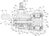
- FIG. 4 is a sectional view of the brushless wiper motor taken along a line A-A in FIG. 3 ;
- FIG. 5 is an enlarged sectional view showing a modified example of a portion "B" circled by a broken line in FIG. 4 ;
- FIG. 6 is a perspective view showing an application example to a modular type wiper apparatus of the brushless wiper motor of FIG. 1 .
- a front windshield 11 is provided on a vehicle 10 such as automotive vehicle.
- a wiper apparatus 12 is mounted on a front end portion of the front windshield 11 in the vehicle 10.
- the wiper apparatus 12 is driven by ON-operation of a wiper switch (not shown) provided within a vehicle compartment, so that extraneous matter (not shown) such as rain water or dust on the front windshield 11 can be wiped.
- the wiper apparatus 12 is provided with: a brushless wiper motor 20; a power transmission mechanism 14 for transmitting a swinging motion of the brushless wiper motor 20 to respective pivot shafts 13a and 13b; and a pair of wiper members 15a and 15b in which proximal sides thereof are respectively fixed to the pivot shafts 13a and 13b, and distal end sides thereof perform reciprocal wiping actions on the front windshield 11 according to swinging motions of the respective pivot shafts 13a and 13b.
- the wiper members 15a and 15b are respectively provided so as to correspond to a driver's seat side and a passenger's seat side.
- the wiper members 15a and 15b are respectively composed of wiper arms 16a and 16b, and wiper blades 17a and 17b attached to the wiper arms 16a and 16b.
- the brushless wiper motor 20 is provided with a housing 21 formed into a predetermined shape by casting molten aluminum material or on the basis of other processing.
- the housing 21 is provided with a motor case part 30 as a first case part and a gear case part 50 as a second case part. That is, the gear case part 50 is formed of the same material (aluminum material) as that of the motor case part 30, and integral with the motor case part 30.
- the motor case part 30 is provided with a cylindrical main body 31 formed into an approximately cylindrical shape.
- An annular bottom portion 32 provided with a bearing attaching hole 32a at a central portion thereof is integrally provided to the cylindrical main body 31 on the same side as the gear case part 50 along an axial direction of the cylindrical main body 31.
- an opening portion 33 opened in an axial direction of a rotor 37 is formed on the opposite side to the gear case part 50 along the axial direction of the cylindrical main body 31.
- the opening portion 33 is closed by a cover member 35.
- the cylindrical main body 31 is provided with: a small diameter portion 31a; and a large diameter portion 31b.
- the small diameter portion 31a is arranged on the cylindrical main body 31 on the same side as the annular bottom portion 32 along an axial direction of the cylindrical main body 31, while the large diameter portion 31b is arranged on the cylindrical main body 31 on the same side as the opening portion 33 along the axial direction of the cylindrical portion 31.
- a step portion 31c is provided inside the cylindrical main body 31 in a radial direction of the cylindrical main body 31, and between the small diameter portion 31a and the large diameter portion 31b.
- a cover-attaching flange portion 31d bulged in the radial direction of the cylindrical main body 31 and attached with the cover member 35 is provided on the large diameter portion 31b on the same side as the opening portion 33.
- step portion 31c performs positioning of the stator 36 to the axial direction of the cylindrical main body 31.
- annular projecting portion 31e is formed on the cover-attaching flange portion 31d so as to project toward the other side (right side in FIG. 4 ) of the cylindrical main body 31 in the axial direction.
- the annular projecting portion 31e enters an annular recessed portion 35d provided to an annular attaching portion 35b of the cover member 35.
- three female screw portions 31f are formed around the cover-attaching flange portion 31d so as to project in a radially outward direction of the cover-attaching flange portion 31d.
- These female screw portions 31f are respectively arranged at equal intervals (at intervals of 120°) along the circumferential direction of the cover-attaching flange portion 31d, and fixing screws S1 are coupled to the female screw portions 31f in a screwing fashion.
- a plurality of cooling fins 34 as a concavo-convex portion is integrally provided on a radially outside part to the cylindrical main body 31.
- the cooling fins 34 are used for increasing an outside surface area of the cylindrical main body 31 to cause many outside regions of the cylindrical main body 31 to contact with external air, thereby improving heat radiation performance of the cylindrical main body 31.
- the cooling fins 34 are arranged in spaced side-by-side relation to each other in the axial direction of the cylindrical main body 31, and provided so as to extend in a circumferential direction of the cylindrical main body 31.
- cooling fins 34 are arranged at two portions of the cylindrical main body 31 on the same side as the output shaft 56 and the gear cover 60 along the circumferential direction of the cylindrical main body 31, without being provided over the whole circumference of the cylindrical main body 31. In this manner, sufficient heat radiation performance and sufficient strength of the motor case part 30 are secured.
- cooling fins may be provided over the whole circumference of the cylindrical main body 31. By providing the cooling fins over the whole circumference of the cylindrical main body 31, fluidity of melted aluminum material at a casting time can be improved, thereby resulting in improvement in cooling performance.
- cooling performance of the motor case part 30 can be further improved, and flowing of rain water can be made easy when the rain water is attached to the cylindrical main body 31.
- the cover member 35 is attached to the opening portion 33 of the cylindrical main body 31.
- the cover member 35 is formed of synthetic resin such as plastic or the like into an approximately circular plate-like shape, and provided with: a bottom wall portion 35a; and the annular attaching portion 35b.
- a recessed portion 35c recessed toward (left side in FIG. 4 ) of the cylindrical attaching portion 31 is provided at a central portion of the bottom wall portion 35a.
- the recessed portion 35c has a function of enhancing rigidity of the cover member 35 and a function of suppressing resonance of the bottom wall portion 35a during operation of the brushless wiper motor 20 to prevent strange noise from being generated.
- the rotor 37 including the rotation shaft 38 does not contact with the recessed portion 35c provided in this cover member 35.
- An annular recessed portion 35d is formed on the annular attaching portion 35b and recessed toward the other side (right side in FIG. 4 ) of the cylindrical main body 31 in the axial direction.
- the annular projecting portion 31e provided on the cover-attaching flange portion 31d enters the annular recessed portion 35d.
- seal agent may be interposed between the annular projecting portion 31e and the annular recessed portion 35d when assembling the cover member 35 to the cylindrical main body 31.
- An annular stator abutting portion 35e is provided on the inside of the annular attaching portion 35b in a radial direction thereof.
- the annular stator abutting portion 35e abuts on the other end side of the stator 35 in the axial direction.
- the annular stator abutting portion 35e performs positioning of the stator 36 to the axial direction of the cylindrical main body 31 in cooperation with the step portion 31c.
- Three screw fixing portions 35f are formed on the outside of the annular attaching portion 35b in the radial direction so as to project outside the annular attaching portion 35b in the radial direction of the annular attaching portion 35b.
- These screw fixing portions 35f are respectively arranged at equal intervals (at intervals of 120°) along the circumferential direction of the annular attaching portion 35b, and screws S1 are inserted into the respective screw fixing portions 35f.
- the fixing screws S1 are used for fixing the cover member 35 to the cylindrical main body 31, and they are coupled to the respective female screw portions 31f in a screwing manner.
- an attaching relationship between the opening portion 33 of the cylindrical main body 31 and the cover member 35 may be set as shown in FIG. 5 .
- the length of the cylindrical main body 31 in the axial direction is made short, so that the end portion of the stator 36 in the axial direction is caused to project from the opening portion 33.
- the end portion of the stator 36 in the axial direction caused to project from the opening portion 33 is covered with the cover member 35.
- the cover member 35 shown as a modified example in FIG. 5 the cover member 35 is not provided with the stator abutting portion 35e shown in FIG. 4 , and an outer fitting portion 35g is provided on the outside of the annular attaching portion 35b in the radial direction instead of the stator abutting portion 35e.
- the cover member 35 is attached to the cylindrical main body 31 by fitting (outer-fitting) of the outer fitting portion 35g to the cover-attaching flange portion 31d without abutting on the stator 36.
- fitting (outer-fitting) of the outer fitting portion 35g to the cover-attaching flange portion 31d without abutting on the stator 36.
- the stator 36 is fixed inside the cylindrical main body 31 forming part of the motor case part 30.
- the stator 36 is formed into an approximately cylindrical shape by stacking a plurality of steel plates (not shown) which are magnetic bodies, and an outer peripheral portion of the stator 36 is caused to contact with the cylindrical main body 31 without any clearance. Therefore, heat accumulated in the stator 36 is efficiently transferred to the cylindrical main body 31.
- Coil bobbins 36a made of resin is insulator, and respectively provided on both sides of the stator 36 in the axial direction.
- the coil bobbin 36a has U-phase, V-phase and W-phase coils 36b (three-phase) wounded thereon. End portions (not shown) of these coils 36b are electrically connected to each other so as to constitute a star connection ("Y"-connection).
- Y star connection
- a connecting method of each coil 36b is not limited to the star connection, but another connecting method such as delta connection (triangular connection) can be adopted.
- Driving currents are respectively supplied to the coils 36b from an electronic part EP composed of switching elements of a control board 70 attached inside the gear cover 60 at a predetermined timing. In this manner, an electromagnetic force is generated in the stator 36, so that the rotor 37 positioned inside the stator 36 is rotationally driven in a predetermined direction with a predetermined driving torque.
- the rotor 37 is rotatably provided inside the stator 36 via a predetermined clearance (air gap).
- the rotor 37 is formed into an approximately columnar shape by stacking steel plates (not shown) which are magnetic material.
- a plurality of permanent magnets 37a formed into an approximately arc shape in cross section are attached on the rotor 37.
- the permanent magnets 37a are arranged at equal intervals (at intervals of 90°) such that polarities are alternated along a circumferential direction of the rotor 37.
- the brushless wiper motor 20 constitutes a brushless motor having an SPM (surface permanent magnet) structure in which the permanent magnets 37a are attached to the rotor 37.
- SPM surface permanent magnet
- IPM internal permanent magnet
- the rotation shaft 38 is fixed at the axial center of the rotor 37 so as to extend through the axial center.
- An approximately central portion of the rotation shaft 38 along an axial direction thereof is rotatably supported by a first ball bearing (bearing) 39 attached to the bearing attaching hole 32a of the cylindrical main body 31. That is, the rotor 37 is rotatably supported by the first ball bearing 39.
- An outer wheel 39a of the first ball bearing 39 is pressed by an annular stopper spring 40, and fixed to the bearing attaching hole 32a.
- the stopper spring 40 is fixed to a stopper fixing portion 32b formed in the annular bottom portion 32 by press-fitting.
- the bearing attaching hole 32a and the stopper fixing portion 32b of the motor case part 30, and the stopper spring 40 collectively constitute the retaining structure of the present invention.
- an inner wheel 39b of the first ball bearing 39 is fixed at an approximately central portion of the rotation shaft 38 in the axial direction by a retaining ring, a caulking or the like (not shown). That is, by fixing the first ball bearing 39 to the bearing attaching hole 32a, the rotation shaft 38 is made immovable in the axial direction. In this manner, the rotation shaft 38 is prevented from wobbling in the axial direction inside the housing 21, thereby resulting in smooth rotation of the rotation shaft 38. Therefore, an excessive load to move the stator 36 in the axial direction is not applied to the stator 36.
- the opposite side of the rotation shaft 38 to the rotor 37 in the axial direction is caused to extend up to the inside of the gear case main body 51 forming part of the gear case part 50.
- One end side (left side in FIG. 4 ) of the rotation shaft 38 in the axial direction is rotatably supported by a second ball bearing 41 attached to a bearing attaching portion 51a of the gear case main body 51.
- the second ball bearing 41 supports the rotation shaft 38 from only a radial direction of the rotation shaft 38, it is made smaller in size than that of the first ball bearing 39.
- a worm 38a forming part of the reduction mechanism (gear mechanism) SD is provided between the first ball bearing 39 and the second ball bearing 41 along the axial direction of the rotation shaft 38.
- spiral worm teeth (not shown) meshed with gear teeth 55a of a worm wheel 55 are formed on an outer peripheral portion of the worm 38a.
- the gear case main body 51 is formed into an approximately bathtub shape with a bottom, and provided with: a bottom portion 52; a side wall portion 53; and an opening portion 54.
- the bottom portion 52 is integrally formed with the annular bottom portion 32 of the cylindrical main body 31 at one side (upper side in FIG. 4 ) thereof through the rotation shaft 38. Furthermore, the other side (lower side in FIG. 4 ) of the annular bottom portion 32 of the cylindrical main body 31 through the rotation shaft 38 partially forms the opening portion 54.
- the worm wheel 55 is rotatably received inside the gear case main body 51.
- the worm wheel 55 is formed of synthetic resin such as POM (polyacetal) plastic or the like in an approximately circular plate shape, and the worm wheel 55 has an outer peripheral portion formed with gear teeth 55a. Worm teeth of the worm 38a are meshed with the gear teeth 55a of the worm wheel 55.
- the worm wheel 55 and the worm 38a collectively constitute the gear mechanism SD housed in the gear case main body 51, and form the reduction mechanism SD for reducing a rotation speed of the rotation shaft 37 (see FIG. 4 ).
- a proximal end side of an output shaft 56 is fixed to an axial center of the worm wheel 55, and the output shaft 56 is rotatably supported by a boss portion 52a integrally provided on the bottom portion 52 of the gear case main body 51.
- a distal end side of the output shaft 56 extends outside the gear case main body 51, and the power transmission mechanism 14 (see FIG. 1 ) is fixed to a distal end portion of the output shaft 56.
- the rotation speed of the rotation shaft 38 is reduced by the reduction mechanism SD, so that an output subjected to a high torque by reduction in speed is transmitted from the output shaft 56 to the power transmission mechanism 14. Therefore, the wiper members 15a and 15b (see FIG. 1 ) are driven in a swinging manner.
- the reduction mechanism SD transmits rotation of the rotor 37 to the wiper members 15a and 15b via the power transmission mechanism 14.
- cooling fins 52b as a concavo-convex portion are integrally provided on the outside of the bottom portion 52 forming part of the gear case part 51.
- These cooling fins 52b are arranged in the vicinity of a switching element (not shown) particularly easy to generate heat and mounted on a control board 70 (see FIG. 4 ). Therefore, heat accumulated in the switching element can be rapidly dissipated outside the gear case main body 51, which results in improvement of the heat radiation performance of the whole control board 70.
- the opening portion 54 of the gear case main body 51 is sealed by the gear cover 60 made of plastic or the like.
- the gear cover 60 is fixed to the gear case main body 51 by three fixing screws S2 as shown in FIG. 3 .
- a control board 70 for controlling rotation of the rotor 37 (the rotation shaft 34) is fixed inside the gear cover 60.
- the control board 70 is electrically connected to a vehicle-mounted battery (not shown) and a wiper switch via an external connector (not shown) of the vehicle 10 which is connected to a connector connection portion 62 provided to the gear cover 60.
- a rotation detecting sensor 71 for detecting rotation states (rotation direction, the number of revolutions or the like) of the rotation shaft 38 is mounted on the control board 70.
- a Hall sensor (Hall IC) for detecting magnetic field is used as the rotation detecting sensor 71.
- the rotation detecting sensor 71 is opposed to a sensor magnet MG fixed to the rotation shaft 38 to be rotated together with the rotation shaft 38.
- the sensor magnet MG is constituted so that polarities thereof alternately appear in a circumferential direction of the sensor magnet MG. Therefore, a pulse signal is outputted from the rotation detecting sensor 71 according to rotation of the sensor magnet MG.
- the CPU (not shown) mounted on the control board 70 monitors a pulse signal from the rotation detecting sensor 71. Therefore, the CPU grasps operation states (position, speed or the like) of the wiper blades 17a and 17b (see FIG. 1 ) to rotationally drive the brushless wiper motor 20.
- the brushless wiper motor 20 When a wiper switch is ON-operated, the brushless wiper motor 20 is rotationally driven. At this time, the CPU mounted on the control board 70 sequentially ON/OFF-controls switching elements corresponding to the U-phase, V-phase and W-phase coils 36b mounted on the control board 70. In this manner, electromagnetic forces are sequentially generated in the U-phase, V-phase and W-phase coils 36b toward the circumferential direction of the stator 36. Therefore, the rotor 37 attached with the permanent magnets 37a is rotated at a predetermined rotation speed in a predetermined rotation direction.
- the wiper switch is switched to "Hi (high speed)"
- the brushless wiper motor 20 is driven at a high speed while enhancing an output of the motor, and such a state is continued for about 2 hours (long time).
- This operation situation correspond to a state that the wiper apparatus 12 (see FIG. 1 ) is continuously operated at a relatively high load.
- the coils 36b rapidly reach high temperature, and heats accumulated in the coils 36b are efficiently dissipated to the outside via the stator 36, the cylindrical main body 31, and the cooling fins 34. Furthermore, even in the switching elements mounted on the control board 70, they rapidly reach high temperature like the coils 36b, because they are ON/OFF-controlled at a high speed, heats accumulated at the switching elements are efficiently dissipated to the outside via the bottom portion 52 and the three cooling fins 52b.
- the temperature of coils in the structure of the present invention and that of the conventional structure under the same operation situation are compared with each other.
- heat radiation performance is largely improved since the motor case part 30 and the gear case part 50 are integrally formed of aluminum material, and the temperature of the coils 36b is "about 80o".
- the temperature of the coils is "about 140o".
- the temperature of the motor case part 30 in the structure of the present invention is "about 60o"
- the temperature of the motor case made of iron in the conventional structure is "about 100o".
- the brushless wiper motor 20 since the motor case part 30 in which the stator 36 is fixed and the gear case part 50 in which the reduction mechanism SD is housed are integrally formed of the same material, heat transferred to the motor case part 30 can be directly dissipated from the motor case part 30 to the outside without intervention of the gear case part 50. Therefore, the brushless wiper motor 20 can be improved in heat radiation performance while enhancing strength in high temperature can be realized.
- the material of the motor case part 30 and the gear case part 50 is aluminum having a high thermal conductivity, sufficient heat radiation performance can be secured. Since the sufficient heat radiation performance can be secured, lack in rigidity can be overcome by making thickness of the motor case part 30 and the gear case part 50 thick.
- the motor case part 30 and the gear case part 50 can be integrally formed by casting or the like, it becomes unnecessary to manufacture the motor case part 30 and the gear case part 50 individually. Furthermore, since it becomes unnecessary to perform pressing or the like to a steel plate like the conventional art, workability of the motor case part 30 and the gear case part 50 can be improved.
- the brushless wiper motor 20 is suitably applicable to a modular type wiper apparatus.
- An application example (modified example) of the brushless wiper motor 20 to the modular type wiper apparatus will be explained with reference to FIG. 6 .
- the female screw portions 31f and the screw fixing portions 35f that is, portions of the cylindrical main body 31 and the cover member 35 bulging outside in the radial direction can be disposed so as to be spaced from a boss portion 52a of the gear case part 50 by a distance "L" .
- the size of the cylindrical main body 31 in the axial direction can be shortened corresponding to unnecessity of provision of a brush holder or the like. Therefore, a projection area range PA of the brushless wiper motor 20 can be made approximately square and a space SP crossing an approximately central portion inside the projection area range PA can be secured at the approximately central portion inside the projection area range PA.
- a pipe frame 81 of a modular type wiper apparatus 80 can be disposed so as to cross the space SP. That is, the brushless wiper motor 20 can be fixed to the pipe frame 81 at a position of the brushless wiper motor 20 approximately corresponding to the gravity center of the brushless wiper motor 20. In this manner, the modular type wiper apparatus 80 can be enhanced in weight balance. In addition, the brushless wiper motor 20 is applied to the modular type wiper apparatus 80 without being provided with the attaching leg portions 57 (see FIG.2 ), and fixed to the pipe frame 81 by an attaching bracket (not shown).
- First and second pivots 82a and 82b are fixed to respective ends of the pipe frame 81 in a longitudinal direction thereof, and the first and second pivots 82a and 82b rotatably support first and second pivot shafts 83a and 83b.
- a power transmission mechanism 84 for transmitting a swinging motion of the output shaft 56 to the first and second pivot shafts 83a and 83b is provided at proximal end portions of the first and second pivot shafts 83a and 83b.
- the proximal end portions of the respective wiper arms 16a and 16b are fixed at distal end portions of the first and second pivot shafts 83a and 83b.
- the power transmission mechanism 84 is composed of: a crank arm 84a fixed to the output shaft 56; a pair of driving levers 84b and 84c fixed to the proximal end portions of the first and second pivot shafts 83a and 83b; a connection rod 84d provided between the respective driving levers 84b and 84c; and a driving rod 84e provided between one driving lever 84c and the crank arm 84a.
- FIG. 7 is a perspective view explaining an assembling procedure of a brushless wiper motor of a second embodiment
- FIG. 8 is a partially sectional view of the brushless wiper motor of FIG. 7 taken along an axial direction of a rotation shaft.
- a brushless wiper motor 90 according to the second embodiment is different only in a fixing structure of the first ball bearing 39 (see FIG. 4 ) to the bearing attaching hole 32a from the first embodiment.
- the annular stopper ring 40 is assembled to the rotation shaft 38 in advance, and it is press-fitted to the stopper fixing portion 32b from the same direction as the attaching direction (axial direction of the rotation shaft 38) of the first ball bearing 39 to the bearing attaching hole 32a, thereby fixing the first ball bearing 39 to the bearing attaching hole 32a.
- the first ball bearing 39 is fixed to the bearing attaching hole 32a.
- the stopper member 91 is fixed to a stopper member attaching portion 92 provided in the vicinity of the bearing attaching hole 32a by press-fitting.
- the bearing attaching hole 32a and the stopper member attaching portion 92, and the stopper member 91 press-fitted into the stopper member attaching portion 92 collectively constitute a retaining structure in the present invention.
- the stopper member 91 is formed into an approximately U-shape by pressing a steel plate or the like.
- the stopper member 91 has a pair of bearing pushing portions 91a which is plugged into the stopper member attaching portion 92.
- a notched portion 91b for avoiding interference with the rotation shaft 38 is provided between the pair of bearing pushing portions 91a.
- the stopper member 91 is provided with a jig pad portion 91c pushed down by a pushing jig (not shown) when the bearing pushing portions 91a are respectively plugged into the stopper member attaching portion 92.
- An extending direction of the jig pad portion 91c is directed in a direction approximately perpendicular to an extending direction of the bearing pushing portions 91a.
- the worm 38a is caused to pass through the bearing attaching hole 32a so that the first ball bearing 39 is attached to the bearing attaching hole 32a.
- the stopper member 91 is caused to face the stopper member attaching portion 92 from a direction crossing the axial direction of the rotation shaft 38.
- the distal end side of the output shaft 56 (see FIG. 4 ) is plugged into the boss portion 52a (see FIG. 4 ) from the inside of the gear case main body 51.
- the gear teeth 55a are caused to mesh with the teeth portion 38a.
- the worm wheel 55 is housed in a normal position in the gear case main body 51, and the reduction mechanism SD composed of the worm 38a and the worm wheel 55 is housed in the gear case main body 51.
- the present invention is not limited to the above-described embodiments, and it can be variously modified without departing from the gist of the present invention.
- the motor case part 30 and the gear case part 50 are made of aluminum, which is the same in material as each other, and integrally formed by casting, but the present invention is not limited to this example, and the motor case part and the gear case part may be integrally formed by using metal material which is another material and utilizing another working method.
- the cooling fins 34 and 52b as the concavo-convex portions are provided on both of the motor case part 30 and the gear case part 50, but the present invention is not limited to this example, and the cooling fins may be provided on either one of the motor case part 30 and the gear case part 50.
- cooling fins 34 as the concavo-convex portion are provided partially so as to extend in the circumferential direction of the cylindrical main body 31, but the present invention is not limited to this example, and the cooling fins may be provided so as to extend in the axial direction of the cylindrical main body 31.
- countless fine recesses (dimples) as the concavo-convex portion may be formed on the outside of the cylindrical main body 31.
- any shape thereof or any number thereof can be adopted.
- the cover member 35 for closing the opening portion 33 is formed of synthetic resin such as plastic or the like, but the present invention is not limited to this example, and the cover member may be formed of another material such as iron, aluminum or the like.
- the cover member 35 is fixed by three fixing screws S1, but a fixing strength of the cover member 35 to the cylindrical main body 31 is not required to be so high. Therefore, fixing may be performed by using two screws, fixing may be performed by engagement of an engaging pawl in one-touch manner, or furthermore, the cover member itself may be connected to the opening portion in a screwing manner. Furthermore, air tightness between the cover member 35 and the cylindrical main body 31 is only required to be maintained.
- the wiper apparatuses 12 and 80 are respectively provided with the power transmission mechanisms 14 and 84, but the present invention is not limited to this, and it may be made unnecessary to have the power transmission mechanisms 14 and 84 in the course of transmission of the swinging motion of the brushless wiper motors 20 and 80 to the pivot shafts 13a and 13b, or 83a and 83b.
- brushless wiper motors corresponding to the respective pivot shafts 13a and 13b, or 83a and 83b are provided in order to transmit power to the respective pivot shafts 13a and 13b, or 83a and 83b.
- the brushless wiper motors 20 and 90 are applied as a driving source of the wiper apparatus 12 wiping the front windshield 11 of the vehicle 10, but the present invention is not limited to this example, and it can also be applied to a driving source of a rear wiper apparatus of a vehicle, or a driving source of a wiper apparatus of a railway vehicle, a ship, a construction machine or the like.
- the brushless wiper motor is used as a driving source of a wiper apparatus mounted on a vehicle such as automotive vehicle, and it is used to drive a wiper arm in a swinging manner to wipe rain water or the like attached to a windshield.
Landscapes
- Engineering & Computer Science (AREA)
- Power Engineering (AREA)
- Mechanical Engineering (AREA)
- Motor Or Generator Frames (AREA)
- Connection Of Motors, Electrical Generators, Mechanical Devices, And The Like (AREA)
Abstract
Description
- The present invention relates to a brushless wiper motor which swings a wiper member provided on a windshield.
- Conventionally, a wiper apparatus for wiping rain water, dust and the like on a windshield is mounted on a vehicle such as automotive vehicle. The wiper apparatus is provided with: a wiper member provided on a windshield; and a wiper motor for swinging the wiper member. By ON-operation of a wiper switch provided within a vehicle compartment, the wiper motor is rotated so that the wiper member is swung on the windshield so as to wipe rain water or dust on the front windshield.
- Such a wiper motor is described in for
example Patent Document 1. The wiper motor (motor with reduction mechanism) described inPatent Document 1 is provided with: a motor part and a reduction mechanism. The motor part is provided with a yoke housing made of metal, and a stator having windings is fixed in the yoke housing. Furthermore, a rotor is rotatably provided inside the stator. In this manner, the wiper motor described in theabove Patent Document 1 is constituted as a brushless motor. - On the other hand, the reduction mechanism is provided with: a gear housing made of aluminum; and a worm portion provided on a rotation shaft of the rotor, and a worm wheel meshed with the worm portion are housed in the gear housing. In this manner, the worm portion and the worm wheel collectively form the reduction mechanism, and the reduction mechanism enhances a torque by reducing rotation of the rotation shaft to output the rotation with the enhanced torque from an output shaft fixed to the worm wheel to the outside.
- Patent Document 1: Japanese Patent application Laid-Open Publication No.:
2010-093977 FIG. 3 ) - In addition, since the wiper motors are mounted on a wide variety of vehicles including a kei car (small-sized vehicle) and a large-sized vehicle, the wiper motors are desired to be reduced in size and weight for improvement of versatility thereof. Furthermore, since various electronic devices are mounted on a vehicle or the like, it is desirable to suppress electric noises occurring during operation of the wiper motor to a maximum extent. Therefore, a brushless motor like the wiper motor described in the
above Patent Document 1 is adopted in the motor part. - However, according to the wiper motor (brushless wiper motor) described in the
above Patent Document 1, since the yoke housing made of metal and the gear housing made of aluminum are coupled to each other, heat transferred to the yoke housing is partially transferred to the gear housing, and then dissipated the outside through the gear housing. That is, in the brushless wiper motor described in theabove Patent Document 1, there is still a lot of room for performing improvement such that heat transferred to the yoke housing can be more efficiently dissipated to the outside. - Here, it is conceivable that the yoke housing is made thin in order to improve heat radiation performance. In this case, however, there is a problem that it is hard to form the yoke housing by pressing (deep drawing) while enhancing the rigidity of the yoke housing.
- An object of the present invention is to provide a brushless wiper motor which can be improved in heat radiation performance while enhancing strength in high temperature, and improved in workability while solving lack in rigidity.
- In an aspect of the present invention, a brushless wiper motor for driving a wiper member in a swinging manner, comprising: a first case part in which a stator is fixed; a rotor rotatably provided inside the stator; a gear mechanism for transmitting rotation of the rotor to the wiper member; and a second case part formed of the same material as that of the first case part and integrally with the first case part, the gear mechanism being received in the second case part.
- In another aspect of the present invention, a concavo-convex portion increased in surface area is formed outside at least one of the first case part and the second case part.
- In another aspect of the present invention, the first case part and the second case part are made of aluminum.
- In another aspect of the present invention, a retaining structure for retaining a bearing for rotatably supporting the rotor is provided in the first case part.
- In another aspect of the present invention, the first case part is provided with an opening portion opened in an axial direction of the rotor, and the opening portion is closed by a cover member which does not contact with the rotor.
- In another aspect of the present invention, an end portion of the stator in an axial direction thereof is provided so as to project from the opening portion, and the end portion of the stator in the axial direction is covered with the cover member.
- According to the present invention, since the first case part in which the stator is fixed and the second case part in which the gear mechanism is housed are integrally formed of the same material, heat transferred to the first case part can be directly dissipated from the first case part to the outside without intervention of the second case part. Therefore, a brushless wiper motor which has been improved in heat radiation performance while enhancing strength in high temperature can be realized.
- Furthermore, by adopting material having a high thermal conductivity as the material of the first and second case parts, lack in rigidity of the first and second case parts can be overcome while sufficient heat radiation performance is maintained.
- Furthermore, since the first and second case parts can be integrally formed by casting or the like, workability of the first and second case parts can be improved.
-
-
FIG. 1 is a view showing a wiper apparatus provided with a brushless wiper motor according to the present invention, and mounted on a vehicle; -
FIG. 2 is a perspective view of the brushless wiper motor ofFIG. 1 , viewed from an output shaft side; -
FIG. 3 is a perspective view of the brushless wiper motor ofFIG. 1 , viewed from a gear cover side; -
FIG. 4 is a sectional view of the brushless wiper motor taken along a line A-A inFIG. 3 ; -
FIG. 5 is an enlarged sectional view showing a modified example of a portion "B" circled by a broken line inFIG. 4 ; -
FIG. 6 is a perspective view showing an application example to a modular type wiper apparatus of the brushless wiper motor ofFIG. 1 ; -
FIG. 7 is a perspective view explaining an assembling procedure of a brushless wiper motor of a second embodiment; and -
FIG. 8 is a partially sectional view of the brushless wiper motor ofFIG. 7 taken along an axial direction of a rotation shaft. - Hereinafter, embodiments of the present invention will be described in detail with reference to the drawings.
-
FIG. 1 is a view showing a wiper apparatus provided with a brushless wiper motor according to the present invention, and mounted on a vehicle;FIG. 2 is a perspective view of the brushless wiper motor ofFIG. 1 , viewed from an output shaft side;FIG. 3 is a perspective view of the brushless wiper motor ofFIG. 1 , viewed from a gear cover side;FIG. 4 is a sectional view of the brushless wiper motor taken along a line A-A inFIG. 3 ;FIG. 5 is an enlarged sectional view showing a modified example of a portion "B" circled by a broken line inFIG. 4 ; andFIG. 6 is a perspective view showing an application example to a modular type wiper apparatus of the brushless wiper motor ofFIG. 1 . - As shown in
FIG. 1 , afront windshield 11 is provided on avehicle 10 such as automotive vehicle. Awiper apparatus 12 is mounted on a front end portion of thefront windshield 11 in thevehicle 10. Thewiper apparatus 12 is driven by ON-operation of a wiper switch (not shown) provided within a vehicle compartment, so that extraneous matter (not shown) such as rain water or dust on thefront windshield 11 can be wiped. - The
wiper apparatus 12 is provided with: abrushless wiper motor 20; apower transmission mechanism 14 for transmitting a swinging motion of thebrushless wiper motor 20 torespective pivot shafts wiper members pivot shafts front windshield 11 according to swinging motions of therespective pivot shafts - The
wiper members wiper members wiper arms wiper blades wiper arms - By rotationally driving the
brushless wiper motor 20, a swinging motion of thebrushless wiper motor 20 is transmitted to therespective pivot shafts power transmission mechanism 14. Therefore, thepivot shafts brushless wiper motor 20 is transmitted to therespective wiper members respective wiping ranges 11a and lib of thefront windshield 11 are wiped by therespective wiper blades - As shown in
FIGS. 2 to 4 , thebrushless wiper motor 20 is provided with ahousing 21 formed into a predetermined shape by casting molten aluminum material or on the basis of other processing. Thehousing 21 is provided with amotor case part 30 as a first case part and agear case part 50 as a second case part. That is, thegear case part 50 is formed of the same material (aluminum material) as that of themotor case part 30, and integral with themotor case part 30. - The
motor case part 30 is provided with a cylindricalmain body 31 formed into an approximately cylindrical shape. Anannular bottom portion 32 provided with abearing attaching hole 32a at a central portion thereof is integrally provided to the cylindricalmain body 31 on the same side as thegear case part 50 along an axial direction of the cylindricalmain body 31. On the other hand, anopening portion 33 opened in an axial direction of arotor 37 is formed on the opposite side to thegear case part 50 along the axial direction of the cylindricalmain body 31. Theopening portion 33 is closed by acover member 35. - The cylindrical
main body 31 is provided with: asmall diameter portion 31a; and alarge diameter portion 31b. Thesmall diameter portion 31a is arranged on the cylindricalmain body 31 on the same side as theannular bottom portion 32 along an axial direction of the cylindricalmain body 31, while thelarge diameter portion 31b is arranged on the cylindricalmain body 31 on the same side as the openingportion 33 along the axial direction of thecylindrical portion 31. In addition, astep portion 31c is provided inside the cylindricalmain body 31 in a radial direction of the cylindricalmain body 31, and between thesmall diameter portion 31a and thelarge diameter portion 31b. Furthermore, a cover-attachingflange portion 31d bulged in the radial direction of the cylindricalmain body 31 and attached with thecover member 35 is provided on thelarge diameter portion 31b on the same side as the openingportion 33. - One end side (left side in
FIG. 4 ) of thestator 36 in the axial direction thereof is caused to abut on thestep portion 31c. That is, thestep portion 31c performs positioning of thestator 36 to the axial direction of the cylindricalmain body 31. Furthermore, an annular projectingportion 31e is formed on the cover-attachingflange portion 31d so as to project toward the other side (right side inFIG. 4 ) of the cylindricalmain body 31 in the axial direction. The annular projectingportion 31e enters an annular recessedportion 35d provided to an annular attachingportion 35b of thecover member 35. - In addition, three
female screw portions 31f are formed around the cover-attachingflange portion 31d so as to project in a radially outward direction of the cover-attachingflange portion 31d. Thesefemale screw portions 31f are respectively arranged at equal intervals (at intervals of 120°) along the circumferential direction of the cover-attachingflange portion 31d, and fixing screws S1 are coupled to thefemale screw portions 31f in a screwing fashion. - A plurality of cooling
fins 34 as a concavo-convex portion is integrally provided on a radially outside part to the cylindricalmain body 31. The coolingfins 34 are used for increasing an outside surface area of the cylindricalmain body 31 to cause many outside regions of the cylindricalmain body 31 to contact with external air, thereby improving heat radiation performance of the cylindricalmain body 31. As shown inFIGS. 2 and3 , the coolingfins 34 are arranged in spaced side-by-side relation to each other in the axial direction of the cylindricalmain body 31, and provided so as to extend in a circumferential direction of the cylindricalmain body 31. - Here, the cooling
fins 34 are arranged at two portions of the cylindricalmain body 31 on the same side as theoutput shaft 56 and thegear cover 60 along the circumferential direction of the cylindricalmain body 31, without being provided over the whole circumference of the cylindricalmain body 31. In this manner, sufficient heat radiation performance and sufficient strength of themotor case part 30 are secured. However, according to the specification (rated power and the like) of the brushless wiper motor, cooling fins may be provided over the whole circumference of the cylindricalmain body 31. By providing the cooling fins over the whole circumference of the cylindricalmain body 31, fluidity of melted aluminum material at a casting time can be improved, thereby resulting in improvement in cooling performance. Furthermore, as compared with one example in which the cooling fins are provided partially, cooling performance of themotor case part 30 can be further improved, and flowing of rain water can be made easy when the rain water is attached to the cylindricalmain body 31. - The
cover member 35 is attached to the openingportion 33 of the cylindricalmain body 31. Thecover member 35 is formed of synthetic resin such as plastic or the like into an approximately circular plate-like shape, and provided with: abottom wall portion 35a; and the annular attachingportion 35b. A recessedportion 35c recessed toward (left side inFIG. 4 ) of the cylindrical attachingportion 31 is provided at a central portion of thebottom wall portion 35a. The recessedportion 35c has a function of enhancing rigidity of thecover member 35 and a function of suppressing resonance of thebottom wall portion 35a during operation of thebrushless wiper motor 20 to prevent strange noise from being generated. Therotor 37 including therotation shaft 38 does not contact with the recessedportion 35c provided in thiscover member 35. - An annular recessed
portion 35d is formed on the annular attachingportion 35b and recessed toward the other side (right side inFIG. 4 ) of the cylindricalmain body 31 in the axial direction. The annular projectingportion 31e provided on the cover-attachingflange portion 31d enters the annular recessedportion 35d. In this manner, by causing the annular projectingportion 31e of the cylindricalmain body 31 and the annular recessedportion 35d of thecover member 35 to be engaged with each other in a concavo-convex manner, a labyrinth effect is generated between the both. That is, sealing performance between the cylindricalmain body 31 and thecover member 35 is secured. However, when it is required to further improve the sealing performance, seal agent may be interposed between the annular projectingportion 31e and the annular recessedportion 35d when assembling thecover member 35 to the cylindricalmain body 31. - An annular
stator abutting portion 35e is provided on the inside of the annular attachingportion 35b in a radial direction thereof. The annularstator abutting portion 35e abuts on the other end side of thestator 35 in the axial direction. The annularstator abutting portion 35e performs positioning of thestator 36 to the axial direction of the cylindricalmain body 31 in cooperation with thestep portion 31c. Incidentally, during operation of thebrushless wiper motor 20, since such a large load as to move thestator 36 in the axial direction is not applied to thestator 36, thecover member 35 is not detached from the cylindricalmain body 31. - Three
screw fixing portions 35f are formed on the outside of the annular attachingportion 35b in the radial direction so as to project outside the annular attachingportion 35b in the radial direction of the annular attachingportion 35b. Thesescrew fixing portions 35f are respectively arranged at equal intervals (at intervals of 120°) along the circumferential direction of the annular attachingportion 35b, and screws S1 are inserted into the respectivescrew fixing portions 35f. The fixing screws S1 are used for fixing thecover member 35 to the cylindricalmain body 31, and they are coupled to the respectivefemale screw portions 31f in a screwing manner. - Incidentally, an attaching relationship between the opening
portion 33 of the cylindricalmain body 31 and thecover member 35 may be set as shown inFIG. 5 . Specifically, the length of the cylindricalmain body 31 in the axial direction is made short, so that the end portion of thestator 36 in the axial direction is caused to project from the openingportion 33. The end portion of thestator 36 in the axial direction caused to project from the openingportion 33 is covered with thecover member 35. In thecover member 35 shown as a modified example inFIG. 5 , thecover member 35 is not provided with thestator abutting portion 35e shown inFIG. 4 , and an outerfitting portion 35g is provided on the outside of the annular attachingportion 35b in the radial direction instead of thestator abutting portion 35e. Thecover member 35 is attached to the cylindricalmain body 31 by fitting (outer-fitting) of the outerfitting portion 35g to the cover-attachingflange portion 31d without abutting on thestator 36. By setting the attaching relationship between the openingportion 33 and thecover member 35 such as shown inFIG. 5 , positioning (insertion amount) of thestator 36 to the cylindricalmain body 31 can be performed for each product without errors. Furthermore, since the length of the cylindricalmain body 31 in the axial direction is made short, it becomes possible to achieve further weight reduction. In addition, since thecover member 35 does not abut on thestator 36, deformation of thecover member 35 due to heat can be prevented in advance. - The
stator 36 is fixed inside the cylindricalmain body 31 forming part of themotor case part 30. Thestator 36 is formed into an approximately cylindrical shape by stacking a plurality of steel plates (not shown) which are magnetic bodies, and an outer peripheral portion of thestator 36 is caused to contact with the cylindricalmain body 31 without any clearance. Therefore, heat accumulated in thestator 36 is efficiently transferred to the cylindricalmain body 31. -
Coil bobbins 36a made of resin is insulator, and respectively provided on both sides of thestator 36 in the axial direction. Thecoil bobbin 36a has U-phase, V-phase and W-phase coils 36b (three-phase) wounded thereon. End portions (not shown) of thesecoils 36b are electrically connected to each other so as to constitute a star connection ("Y"-connection). However, a connecting method of eachcoil 36b is not limited to the star connection, but another connecting method such as delta connection (triangular connection) can be adopted. - Driving currents are respectively supplied to the
coils 36b from an electronic part EP composed of switching elements of acontrol board 70 attached inside thegear cover 60 at a predetermined timing. In this manner, an electromagnetic force is generated in thestator 36, so that therotor 37 positioned inside thestator 36 is rotationally driven in a predetermined direction with a predetermined driving torque. - The
rotor 37 is rotatably provided inside thestator 36 via a predetermined clearance (air gap). Therotor 37 is formed into an approximately columnar shape by stacking steel plates (not shown) which are magnetic material. A plurality ofpermanent magnets 37a formed into an approximately arc shape in cross section are attached on therotor 37. - The
permanent magnets 37a are arranged at equal intervals (at intervals of 90°) such that polarities are alternated along a circumferential direction of therotor 37. Thus, thebrushless wiper motor 20 constitutes a brushless motor having an SPM (surface permanent magnet) structure in which thepermanent magnets 37a are attached to therotor 37. However, the present invention is not limited to the brushless motor having an SPM structure but a brushless motor having an IPM (interior permanent magnet) structure in which permanent magnets are embedded in therotor 37 may be adopted. - The
rotation shaft 38 is fixed at the axial center of therotor 37 so as to extend through the axial center. An approximately central portion of therotation shaft 38 along an axial direction thereof is rotatably supported by a first ball bearing (bearing) 39 attached to thebearing attaching hole 32a of the cylindricalmain body 31. That is, therotor 37 is rotatably supported by thefirst ball bearing 39. Anouter wheel 39a of thefirst ball bearing 39 is pressed by anannular stopper spring 40, and fixed to thebearing attaching hole 32a. Thestopper spring 40 is fixed to astopper fixing portion 32b formed in theannular bottom portion 32 by press-fitting. Here, thebearing attaching hole 32a and thestopper fixing portion 32b of themotor case part 30, and thestopper spring 40 collectively constitute the retaining structure of the present invention. - On the other hand, an
inner wheel 39b of thefirst ball bearing 39 is fixed at an approximately central portion of therotation shaft 38 in the axial direction by a retaining ring, a caulking or the like (not shown). That is, by fixing thefirst ball bearing 39 to thebearing attaching hole 32a, therotation shaft 38 is made immovable in the axial direction. In this manner, therotation shaft 38 is prevented from wobbling in the axial direction inside thehousing 21, thereby resulting in smooth rotation of therotation shaft 38. Therefore, an excessive load to move thestator 36 in the axial direction is not applied to thestator 36. - The opposite side of the
rotation shaft 38 to therotor 37 in the axial direction is caused to extend up to the inside of the gear casemain body 51 forming part of thegear case part 50. One end side (left side inFIG. 4 ) of therotation shaft 38 in the axial direction is rotatably supported by a second ball bearing 41 attached to abearing attaching portion 51a of the gear casemain body 51. Here, since the second ball bearing 41 supports therotation shaft 38 from only a radial direction of therotation shaft 38, it is made smaller in size than that of thefirst ball bearing 39. - A
worm 38a forming part of the reduction mechanism (gear mechanism) SD is provided between thefirst ball bearing 39 and the second ball bearing 41 along the axial direction of therotation shaft 38. Incidentally, spiral worm teeth (not shown) meshed withgear teeth 55a of aworm wheel 55 are formed on an outer peripheral portion of theworm 38a. - The gear case
main body 51 is formed into an approximately bathtub shape with a bottom, and provided with: abottom portion 52; aside wall portion 53; and anopening portion 54. Thebottom portion 52 is integrally formed with theannular bottom portion 32 of the cylindricalmain body 31 at one side (upper side inFIG. 4 ) thereof through therotation shaft 38. Furthermore, the other side (lower side inFIG. 4 ) of theannular bottom portion 32 of the cylindricalmain body 31 through therotation shaft 38 partially forms the openingportion 54. - The
worm wheel 55 is rotatably received inside the gear casemain body 51. Theworm wheel 55 is formed of synthetic resin such as POM (polyacetal) plastic or the like in an approximately circular plate shape, and theworm wheel 55 has an outer peripheral portion formed withgear teeth 55a. Worm teeth of theworm 38a are meshed with thegear teeth 55a of theworm wheel 55. Theworm wheel 55 and theworm 38a collectively constitute the gear mechanism SD housed in the gear casemain body 51, and form the reduction mechanism SD for reducing a rotation speed of the rotation shaft 37 (seeFIG. 4 ). - A proximal end side of an
output shaft 56 is fixed to an axial center of theworm wheel 55, and theoutput shaft 56 is rotatably supported by aboss portion 52a integrally provided on thebottom portion 52 of the gear casemain body 51. A distal end side of theoutput shaft 56 extends outside the gear casemain body 51, and the power transmission mechanism 14 (seeFIG. 1 ) is fixed to a distal end portion of theoutput shaft 56. In this manner, the rotation speed of therotation shaft 38 is reduced by the reduction mechanism SD, so that an output subjected to a high torque by reduction in speed is transmitted from theoutput shaft 56 to thepower transmission mechanism 14. Therefore, thewiper members FIG. 1 ) are driven in a swinging manner. Thus, the reduction mechanism SD transmits rotation of therotor 37 to thewiper members power transmission mechanism 14. - As shown in
FIGS. 2 and3 , three attachinglegs 57 are provided integrally around the gear casemain body 51.Rubber bushes 58 are respectively attached to these attachinglegs 57. In this manner, with thebrushless wiper motor 20 mounted on the vehicle 10 (seeFIG. 1 ), vibrations of thebrushless wiper motor 20 are hard to be transmitted to thevehicle 10. Furthermore, on the contrary, vibrations of thevehicle 10 are hard to be transmitted to thebrushless wiper motor 20. - As shown in
FIG. 2 , three coolingfins 52b as a concavo-convex portion are integrally provided on the outside of thebottom portion 52 forming part of thegear case part 51. These coolingfins 52b are arranged in the vicinity of a switching element (not shown) particularly easy to generate heat and mounted on a control board 70 (seeFIG. 4 ). Therefore, heat accumulated in the switching element can be rapidly dissipated outside the gear casemain body 51, which results in improvement of the heat radiation performance of thewhole control board 70. - The opening
portion 54 of the gear casemain body 51 is sealed by thegear cover 60 made of plastic or the like. Thegear cover 60 is fixed to the gear casemain body 51 by three fixing screws S2 as shown inFIG. 3 . Acontrol board 70 for controlling rotation of the rotor 37 (the rotation shaft 34) is fixed inside thegear cover 60. Thecontrol board 70 is electrically connected to a vehicle-mounted battery (not shown) and a wiper switch via an external connector (not shown) of thevehicle 10 which is connected to a connector connection portion 62 provided to thegear cover 60. - A
rotation detecting sensor 71 for detecting rotation states (rotation direction, the number of revolutions or the like) of therotation shaft 38 is mounted on thecontrol board 70. Here, as therotation detecting sensor 71, a Hall sensor (Hall IC) for detecting magnetic field is used. Therotation detecting sensor 71 is opposed to a sensor magnet MG fixed to therotation shaft 38 to be rotated together with therotation shaft 38. Here, the sensor magnet MG is constituted so that polarities thereof alternately appear in a circumferential direction of the sensor magnet MG. Therefore, a pulse signal is outputted from therotation detecting sensor 71 according to rotation of the sensor magnet MG. - The CPU (not shown) mounted on the
control board 70 monitors a pulse signal from therotation detecting sensor 71. Therefore, the CPU grasps operation states (position, speed or the like) of thewiper blades FIG. 1 ) to rotationally drive thebrushless wiper motor 20. - Next, the operation of the
brushless wiper motor 20 formed in the above manner will be described in detail with reference to the drawings. - When a wiper switch is ON-operated, the
brushless wiper motor 20 is rotationally driven. At this time, the CPU mounted on thecontrol board 70 sequentially ON/OFF-controls switching elements corresponding to the U-phase, V-phase and W-phase coils 36b mounted on thecontrol board 70. In this manner, electromagnetic forces are sequentially generated in the U-phase, V-phase and W-phase coils 36b toward the circumferential direction of thestator 36. Therefore, therotor 37 attached with thepermanent magnets 37a is rotated at a predetermined rotation speed in a predetermined rotation direction. - For example, during heavy rain, the wiper switch is switched to "Hi (high speed)", the
brushless wiper motor 20 is driven at a high speed while enhancing an output of the motor, and such a state is continued for about 2 hours (long time). This operation situation correspond to a state that the wiper apparatus 12 (seeFIG. 1 ) is continuously operated at a relatively high load. - In this operation situation, the
coils 36b rapidly reach high temperature, and heats accumulated in thecoils 36b are efficiently dissipated to the outside via thestator 36, the cylindricalmain body 31, and the coolingfins 34. Furthermore, even in the switching elements mounted on thecontrol board 70, they rapidly reach high temperature like thecoils 36b, because they are ON/OFF-controlled at a high speed, heats accumulated at the switching elements are efficiently dissipated to the outside via thebottom portion 52 and the three coolingfins 52b. - Here, the temperature of coils in the structure of the present invention and that of the conventional structure under the same operation situation are compared with each other. As a result, in the structure of the present invention, heat radiation performance is largely improved since the
motor case part 30 and thegear case part 50 are integrally formed of aluminum material, and the temperature of thecoils 36b is "about 80º". On the other hand, in the conventional structure, since the motor case is made of iron, heat radiation performance is poor as compared with the structure of the present invention, and the temperature of the coils is "about 140º". Furthermore, the temperature of themotor case part 30 in the structure of the present invention is "about 60º", while the temperature of the motor case made of iron in the conventional structure is "about 100º". - As described above in detail, in the
brushless wiper motor 20 according to this embodiment, since themotor case part 30 in which thestator 36 is fixed and thegear case part 50 in which the reduction mechanism SD is housed are integrally formed of the same material, heat transferred to themotor case part 30 can be directly dissipated from themotor case part 30 to the outside without intervention of thegear case part 50. Therefore, thebrushless wiper motor 20 can be improved in heat radiation performance while enhancing strength in high temperature can be realized. - Furthermore, since the material of the
motor case part 30 and thegear case part 50 is aluminum having a high thermal conductivity, sufficient heat radiation performance can be secured. Since the sufficient heat radiation performance can be secured, lack in rigidity can be overcome by making thickness of themotor case part 30 and thegear case part 50 thick. - In addition, since the
motor case part 30 and thegear case part 50 can be integrally formed by casting or the like, it becomes unnecessary to manufacture themotor case part 30 and thegear case part 50 individually. Furthermore, since it becomes unnecessary to perform pressing or the like to a steel plate like the conventional art, workability of themotor case part 30 and thegear case part 50 can be improved. - Here, the
brushless wiper motor 20 is suitably applicable to a modular type wiper apparatus. An application example (modified example) of thebrushless wiper motor 20 to the modular type wiper apparatus will be explained with reference toFIG. 6 . - In the
brushless wiper motor 20, as shown inFIG. 2 , thefemale screw portions 31f and thescrew fixing portions 35f, that is, portions of the cylindricalmain body 31 and thecover member 35 bulging outside in the radial direction can be disposed so as to be spaced from aboss portion 52a of thegear case part 50 by a distance "L" . Furthermore, the size of the cylindricalmain body 31 in the axial direction can be shortened corresponding to unnecessity of provision of a brush holder or the like. Therefore, a projection area range PA of thebrushless wiper motor 20 can be made approximately square and a space SP crossing an approximately central portion inside the projection area range PA can be secured at the approximately central portion inside the projection area range PA. - Therefore, as shown in
FIG. 6 , apipe frame 81 of a modulartype wiper apparatus 80 can be disposed so as to cross the space SP. That is, thebrushless wiper motor 20 can be fixed to thepipe frame 81 at a position of thebrushless wiper motor 20 approximately corresponding to the gravity center of thebrushless wiper motor 20. In this manner, the modulartype wiper apparatus 80 can be enhanced in weight balance. In addition, thebrushless wiper motor 20 is applied to the modulartype wiper apparatus 80 without being provided with the attaching leg portions 57 (seeFIG.2 ), and fixed to thepipe frame 81 by an attaching bracket (not shown). - First and
second pivots pipe frame 81 in a longitudinal direction thereof, and the first andsecond pivots second pivot shafts power transmission mechanism 84 for transmitting a swinging motion of theoutput shaft 56 to the first andsecond pivot shafts second pivot shafts respective wiper arms FIG. 1 ) are fixed at distal end portions of the first andsecond pivot shafts - The
power transmission mechanism 84 is composed of: acrank arm 84a fixed to theoutput shaft 56; a pair of drivinglevers second pivot shafts connection rod 84d provided between the respective driving levers 84b and 84c; and a drivingrod 84e provided between one drivinglever 84c and thecrank arm 84a. - Next, the second embodiment of the present invention will be described in detail with reference to the drawings, and detail description about portions the same in function as those of the first embodiment is omitted, and those are denoted by the same reference characters as those of the first embodiment.
-
FIG. 7 is a perspective view explaining an assembling procedure of a brushless wiper motor of a second embodiment; andFIG. 8 is a partially sectional view of the brushless wiper motor ofFIG. 7 taken along an axial direction of a rotation shaft. - As shown in
FIGS. 7 and8 , abrushless wiper motor 90 according to the second embodiment is different only in a fixing structure of the first ball bearing 39 (seeFIG. 4 ) to thebearing attaching hole 32a from the first embodiment. Specifically, in the first embodiment, as shown inFIG. 4 , theannular stopper ring 40 is assembled to therotation shaft 38 in advance, and it is press-fitted to thestopper fixing portion 32b from the same direction as the attaching direction (axial direction of the rotation shaft 38) of thefirst ball bearing 39 to thebearing attaching hole 32a, thereby fixing thefirst ball bearing 39 to thebearing attaching hole 32a. - On the other hand, in the second embodiment, as shown in
FIGS. 7 and8 , by using a stopper member 93 separated from therotor unit 91, thefirst ball bearing 39 is fixed to thebearing attaching hole 32a. Here, thestopper member 91 is fixed to a stoppermember attaching portion 92 provided in the vicinity of thebearing attaching hole 32a by press-fitting. In addition, thebearing attaching hole 32a and the stoppermember attaching portion 92, and thestopper member 91 press-fitted into the stoppermember attaching portion 92 collectively constitute a retaining structure in the present invention. - The
stopper member 91 is formed into an approximately U-shape by pressing a steel plate or the like. Thestopper member 91 has a pair of bearing pushingportions 91a which is plugged into the stoppermember attaching portion 92. A notchedportion 91b for avoiding interference with therotation shaft 38 is provided between the pair of bearing pushingportions 91a. Furthermore, thestopper member 91 is provided with ajig pad portion 91c pushed down by a pushing jig (not shown) when thebearing pushing portions 91a are respectively plugged into the stoppermember attaching portion 92. An extending direction of thejig pad portion 91c is directed in a direction approximately perpendicular to an extending direction of thebearing pushing portions 91a. - For assembling the
first ball bearing 39 to thebearing attaching hole 32a, first, as shown by arrow (1) inFIG. 7 , a portion of therotation shaft 38 on theworm 38a side is caused to face thebearing attaching hole 32a from the same side as the cylindricalmain body 31. Theworm 38a is caused to pass through thebearing attaching hole 32a so that thefirst ball bearing 39 is attached to thebearing attaching hole 32a. Next, as shown by a two-dot chain line arrow (2) inFIG. 7 , thestopper member 91 is caused to face the stoppermember attaching portion 92 from a direction crossing the axial direction of therotation shaft 38. While a pressing jig is caused to abut on ajig abutting portion 91c, thestopper member 91 is pressed toward the stoppermember attaching portion 92. Therefore, as shown inFIG. 8 , thefirst ball bearing 39 is clamped between a portion formed with thebearing attaching hole 32a along the axial direction of therotation shaft 38 and thestopper member 91, so that assembling of theworm 38a (rotation shaft 38) to the gear casemain body 51 is completed. - Next, as shown by an arrow (3) in
FIG. 7 , the distal end side of the output shaft 56 (seeFIG. 4 ) is plugged into theboss portion 52a (seeFIG. 4 ) from the inside of the gear casemain body 51. At this time, by swinging theworm wheel 55 in forward and reverse directions, thegear teeth 55a are caused to mesh with theteeth portion 38a. In this manner, theworm wheel 55 is housed in a normal position in the gear casemain body 51, and the reduction mechanism SD composed of theworm 38a and theworm wheel 55 is housed in the gear casemain body 51. - In the second embodiment formed in the above manner, operation and effects similar to those of the first embodiment can be achieved. In addition, in the second embodiment, since the
stopper member 91 is attached to the stoppermember attaching portion 92 in the direction crossing the axial direction of therotation shaft 38, even if a large axial force is applied to therotation shaft 38 during operation of the reduction mechanism SD, movement of therotation shaft 38 in the axial direction thereof or wobbling thereof is securely prevented. - It goes without saying that the present invention is not limited to the above-described embodiments, and it can be variously modified without departing from the gist of the present invention. In the above embodiments, the
motor case part 30 and thegear case part 50 are made of aluminum, which is the same in material as each other, and integrally formed by casting, but the present invention is not limited to this example, and the motor case part and the gear case part may be integrally formed by using metal material which is another material and utilizing another working method. - Furthermore, in the above embodiments, the cooling
fins motor case part 30 and thegear case part 50, but the present invention is not limited to this example, and the cooling fins may be provided on either one of themotor case part 30 and thegear case part 50. In this case, for suppressing lowering of heat radiation performance of the whole brushless wiper motor, it is desirable to provide the cooling fines on one of themotor case part 30 and thegear case part 50 which reaches a higher temperature during operation of the brushless wiper motor. - In addition, in the above embodiments, the example where the cooling
fins 34 as the concavo-convex portion are provided partially so as to extend in the circumferential direction of the cylindricalmain body 31, but the present invention is not limited to this example, and the cooling fins may be provided so as to extend in the axial direction of the cylindricalmain body 31. Furthermore, for example, countless fine recesses (dimples) as the concavo-convex portion may be formed on the outside of the cylindricalmain body 31. In short, when the concavo-convex portion can increase the outside surface area of the cylindricalmain body 31, any shape thereof or any number thereof can be adopted. - Furthermore, in the above embodiments, the
cover member 35 for closing the openingportion 33 is formed of synthetic resin such as plastic or the like, but the present invention is not limited to this example, and the cover member may be formed of another material such as iron, aluminum or the like. In addition, in the above embodiments, thecover member 35 is fixed by three fixing screws S1, but a fixing strength of thecover member 35 to the cylindricalmain body 31 is not required to be so high. Therefore, fixing may be performed by using two screws, fixing may be performed by engagement of an engaging pawl in one-touch manner, or furthermore, the cover member itself may be connected to the opening portion in a screwing manner. Furthermore, air tightness between thecover member 35 and the cylindricalmain body 31 is only required to be maintained. - Furthermore, in the above embodiments, the
wiper apparatuses power transmission mechanisms power transmission mechanisms brushless wiper motors pivot shafts respective pivot shafts respective pivot shafts - Furthermore, in the above embodiments, the
brushless wiper motors wiper apparatus 12 wiping thefront windshield 11 of thevehicle 10, but the present invention is not limited to this example, and it can also be applied to a driving source of a rear wiper apparatus of a vehicle, or a driving source of a wiper apparatus of a railway vehicle, a ship, a construction machine or the like. - The brushless wiper motor is used as a driving source of a wiper apparatus mounted on a vehicle such as automotive vehicle, and it is used to drive a wiper arm in a swinging manner to wipe rain water or the like attached to a windshield.
Claims (6)
- A brushless wiper motor for driving a wiper member in a swinging manner, comprising:a first case part in which a stator is fixed;a rotor rotatably provided inside the stator;a gear mechanism for transmitting rotation of the rotor to the wiper member; anda second case part formed of the same material as that of the first case part and integrally with the first case part, the gear mechanism being housed in the second case part.
- The brushless wiper motor according to claim 1, wherein a concavo-convex portion increasing a surface area at least one of the first case part and the second case part is formed outside said at least one of the first case part and the second case part.
- The brushless wiper motor according to claim 1, wherein the first case part and the second case part are made of aluminum.
- The brushless wiper motor according to claim 1, wherein a retaining structure for retaining a bearing for rotatably supporting the rotor is provided inside the first case part.
- The brushless wiper motor according to claim 1, wherein the first case part is provided with an opening portion opened in an axial direction of the rotor, and the opening portion is closed by a cover member which does not contact with the rotor.
- The brushless wiper motor according to claim 5, wherein an end portion of the stator in an axial direction thereof is provided so as to project from the opening portion, and the end portion of the stator in the axial direction is covered with the cover member.
Applications Claiming Priority (2)
| Application Number | Priority Date | Filing Date | Title |
|---|---|---|---|
| JP2014145165 | 2014-07-15 | ||
| PCT/JP2015/070112 WO2016010023A1 (en) | 2014-07-15 | 2015-07-14 | Brushless wiper motor |
Publications (2)
| Publication Number | Publication Date |
|---|---|
| EP3170706A1 true EP3170706A1 (en) | 2017-05-24 |
| EP3170706A4 EP3170706A4 (en) | 2018-03-28 |
Family
ID=55078513
Family Applications (1)
| Application Number | Title | Priority Date | Filing Date |
|---|---|---|---|
| EP15821881.8A Withdrawn EP3170706A4 (en) | 2014-07-15 | 2015-07-14 | Brushless wiper motor |
Country Status (4)
| Country | Link |
|---|---|
| US (1) | US20170207684A1 (en) |
| EP (1) | EP3170706A4 (en) |
| JP (1) | JP6634372B2 (en) |
| WO (1) | WO2016010023A1 (en) |
Families Citing this family (17)
| Publication number | Priority date | Publication date | Assignee | Title |
|---|---|---|---|---|
| JP6431774B2 (en) * | 2015-01-19 | 2018-11-28 | 株式会社ミツバ | Drive device |
| JP6664878B2 (en) * | 2015-02-17 | 2020-03-13 | 株式会社ミツバ | Motor device and wiper device |
| JP6608304B2 (en) * | 2016-02-17 | 2019-11-20 | 株式会社ミツバ | Motor and motor with reduction gear |
| JP2018011398A (en) * | 2016-07-12 | 2018-01-18 | 株式会社ミツバ | Brushless Wiper Motor |
| JP6661240B2 (en) * | 2016-08-31 | 2020-03-11 | 株式会社ミツバ | Motor device |
| FR3056845B1 (en) | 2016-09-26 | 2021-07-30 | Valeo Systemes Dessuyage | BRUSHLESS DC ELECTRIC MOTOR FOR AUTOMOTIVE VEHICLE WIPER SYSTEM |
| FR3056846B1 (en) | 2016-09-26 | 2022-08-12 | Valeo Systemes Dessuyage | BRUSHLESS DC ELECTRIC MOTOR FOR MOTOR VEHICLE WIPER SYSTEM |
| DE102017107612A1 (en) | 2017-04-10 | 2018-10-11 | Valeo Systèmes d'Essuyage | Brushless electric motor and method of manufacturing the electric motor |
| FR3066968B1 (en) | 2017-06-02 | 2021-01-01 | Valeo Systemes Dessuyage | MOTOR-REDUCER FOR AUTOMOTIVE VEHICLE WIPING SYSTEM |
| DE102017121217A1 (en) * | 2017-09-13 | 2019-03-14 | Valeo Systèmes d'Essuyage | Brushless electric motor and method for its assembly |
| JP6949685B2 (en) * | 2017-11-29 | 2021-10-13 | 株式会社ミツバ | Motor device |
| CN108199519A (en) * | 2017-12-29 | 2018-06-22 | 昆山腾荣机械有限公司 | A kind of light durable New energy automobile motor housing |
| DE102018111855A1 (en) * | 2018-05-17 | 2019-11-21 | Valeo Systèmes d'Essuyage | Electric drive device and windscreen wiper motor |
| DE102018117495B4 (en) * | 2018-07-19 | 2026-05-07 | Valeo Wischersysteme Gmbh | Brushless electric motor, especially for a windshield wiper motor |
| DE102018123039A1 (en) * | 2018-09-19 | 2020-03-19 | Fte Automotive Gmbh | Electrical clutch actuator with a one-piece housing |
| JP7065753B2 (en) * | 2018-11-21 | 2022-05-12 | 株式会社ミツバ | Motor device and its manufacturing method |
| DE102022214426A1 (en) | 2022-12-28 | 2024-07-04 | Robert Bosch Gesellschaft mit beschränkter Haftung | Method for producing a transmission drive unit, in particular for a braking device in a motor vehicle, and a transmission drive unit |
Family Cites Families (32)
| Publication number | Priority date | Publication date | Assignee | Title |
|---|---|---|---|---|
| JPH05111211A (en) * | 1991-10-18 | 1993-04-30 | Mitsubishi Electric Corp | Electric motor |
| GB9615316D0 (en) * | 1995-11-16 | 1996-09-04 | Lucas Ind Plc | Improvements in electric actuators for vehicle powered steering systems |
| JP4121262B2 (en) * | 2001-10-02 | 2008-07-23 | カヤバ工業株式会社 | Manufacturing method of power transmission device and manufacturing method of electric power steering device |
| US6944906B2 (en) * | 2002-05-15 | 2005-09-20 | Trico Products Corporation | Direct drive windshield wiper assembly |
| JP3836397B2 (en) * | 2002-05-21 | 2006-10-25 | 自動車電機工業株式会社 | Motor case |
| JP2004320879A (en) * | 2003-04-15 | 2004-11-11 | Mitsuba Corp | Motor with speed reduction mechanism |
| EP2302055B1 (en) * | 2004-11-12 | 2014-08-27 | Asuragen, Inc. | Methods and compositions involving miRNA and miRNA inhibitor molecules |
| JP2006240318A (en) * | 2005-02-28 | 2006-09-14 | Asmo Co Ltd | Module type windshield wiper device |
| JP4129875B2 (en) * | 2005-03-08 | 2008-08-06 | 東京パーツ工業株式会社 | Electric motor with reduction mechanism |
| JP2007097352A (en) * | 2005-09-30 | 2007-04-12 | Mitsuba Corp | Electric motor |
| WO2007055296A1 (en) * | 2005-11-10 | 2007-05-18 | Nsk Ltd. | Electric power steering device |
| FR2893575B1 (en) * | 2005-11-23 | 2009-06-12 | Falgayras Sa Sa | TRAINING DEVICE, IN PARTICULAR FOR TRAINING A WINDSCREEN WIPER |
| JP2007181383A (en) * | 2005-12-28 | 2007-07-12 | Asmo Co Ltd | Motor device and wiper device |
| JP2007259605A (en) * | 2006-03-24 | 2007-10-04 | Mitsuba Corp | Motor with decelerator mechanism |
| JP4294657B2 (en) * | 2006-06-20 | 2009-07-15 | アスモ株式会社 | Coupling device, motor device, and wiper motor |
| JP4914261B2 (en) * | 2007-03-23 | 2012-04-11 | アスモ株式会社 | Motor equipment |
| JP2008253049A (en) * | 2007-03-30 | 2008-10-16 | Mitsuba Corp | Electric motor |
| JP2008289260A (en) * | 2007-05-16 | 2008-11-27 | Nsk Ltd | Rotating electric machine and electric power steering device |
| JP2009148115A (en) * | 2007-12-17 | 2009-07-02 | Aisin Seiki Co Ltd | motor |
| JP5374312B2 (en) * | 2009-10-09 | 2013-12-25 | Ntn株式会社 | In-wheel motor drive device |
| JP5452332B2 (en) * | 2010-04-12 | 2014-03-26 | 株式会社ミツバ | Motor with reduction mechanism |
| CN103249607B (en) * | 2010-12-10 | 2016-04-20 | 株式会社美姿把 | Wiper motor |
| JP2012147519A (en) * | 2011-01-07 | 2012-08-02 | Mitsuba Corp | Motor device |
| JP2012186981A (en) * | 2011-03-08 | 2012-09-27 | Yamaha Motor Electronics Co Ltd | Motor |
| DE102011055336A1 (en) * | 2011-11-15 | 2013-05-16 | Valeo Systèmes d'Essuyage | wiper motor |
| DE102012100776A1 (en) * | 2012-01-31 | 2013-08-01 | Valeo Systèmes d'Essuyage | wiper motor |
| DE102012102900A1 (en) * | 2012-04-03 | 2013-10-10 | Valeo Wischersysteme Gmbh | Device for detecting the angular position of a shaft of a windscreen wiper motor and windscreen wiper motor with a device for detecting the angular position |
| JP2013223317A (en) * | 2012-04-16 | 2013-10-28 | Mitsuba Corp | Brushless windshield wiper motor |
| MX357242B (en) * | 2012-04-16 | 2018-07-02 | Mitsuba Corp | Brushless motor and wiper device. |
| US8891561B2 (en) * | 2012-07-16 | 2014-11-18 | Broadcom Corporation | 50 Gb/s ethernet using serializer/deserializer lanes |
| US8945314B2 (en) * | 2012-07-30 | 2015-02-03 | Ecolab Usa Inc. | Biodegradable stability binding agent for a solid detergent |
| DE202013004746U1 (en) * | 2012-08-07 | 2013-10-10 | Abm Greiffenberger Antriebstechnik Gmbh | asynchronous |
-
2015
- 2015-07-14 US US15/326,060 patent/US20170207684A1/en not_active Abandoned
- 2015-07-14 EP EP15821881.8A patent/EP3170706A4/en not_active Withdrawn
- 2015-07-14 WO PCT/JP2015/070112 patent/WO2016010023A1/en not_active Ceased
- 2015-07-14 JP JP2016534441A patent/JP6634372B2/en active Active
Also Published As
| Publication number | Publication date |
|---|---|
| EP3170706A4 (en) | 2018-03-28 |
| US20170207684A1 (en) | 2017-07-20 |
| WO2016010023A1 (en) | 2016-01-21 |
| JP6634372B2 (en) | 2020-01-22 |
| JPWO2016010023A1 (en) | 2017-04-27 |
Similar Documents
| Publication | Publication Date | Title |
|---|---|---|
| EP3170706A1 (en) | Brushless wiper motor | |
| EP3171491B1 (en) | Brushless wiper motor | |
| EP3171489B1 (en) | Brushless wiper motor and method for assembling same | |
| US10336299B2 (en) | Brushless wiper motor | |
| US10116186B2 (en) | Brushless wiper motor | |
| US10442401B2 (en) | Brushless wiper motor | |
| US10533653B2 (en) | Motor with speed reduction mechanism | |
| JP5909127B2 (en) | Wiper motor | |
| EP3093202B1 (en) | Wiper device | |
| JP6640586B2 (en) | Brushless motor | |
| JP6410393B2 (en) | Wiper motor | |
| JP2017131014A (en) | Brushless motor | |
| JP2017013739A (en) | Support member |
Legal Events
| Date | Code | Title | Description |
|---|---|---|---|
| STAA | Information on the status of an ep patent application or granted ep patent |
Free format text: STATUS: THE INTERNATIONAL PUBLICATION HAS BEEN MADE |
|
| PUAI | Public reference made under article 153(3) epc to a published international application that has entered the european phase |
Free format text: ORIGINAL CODE: 0009012 |
|
| STAA | Information on the status of an ep patent application or granted ep patent |
Free format text: STATUS: REQUEST FOR EXAMINATION WAS MADE |
|
| 17P | Request for examination filed |
Effective date: 20170215 |
|
| AK | Designated contracting states |
Kind code of ref document: A1 Designated state(s): AL AT BE BG CH CY CZ DE DK EE ES FI FR GB GR HR HU IE IS IT LI LT LU LV MC MK MT NL NO PL PT RO RS SE SI SK SM TR |
|
| AX | Request for extension of the european patent |
Extension state: BA ME |
|
| DAV | Request for validation of the european patent (deleted) | ||
| DAX | Request for extension of the european patent (deleted) | ||
| A4 | Supplementary search report drawn up and despatched |
Effective date: 20180226 |
|
| RIC1 | Information provided on ipc code assigned before grant |
Ipc: H02K 5/06 20060101ALI20180220BHEP Ipc: H02K 7/116 20060101ALI20180220BHEP Ipc: H02K 7/06 20060101ALN20180220BHEP Ipc: H02K 5/16 20060101ALN20180220BHEP Ipc: H02K 21/14 20060101ALN20180220BHEP Ipc: B60S 1/08 20060101AFI20180220BHEP Ipc: H02K 7/08 20060101ALN20180220BHEP |
|
| STAA | Information on the status of an ep patent application or granted ep patent |
Free format text: STATUS: EXAMINATION IS IN PROGRESS |
|
| 17Q | First examination report despatched |
Effective date: 20190729 |
|
| STAA | Information on the status of an ep patent application or granted ep patent |
Free format text: STATUS: THE APPLICATION IS DEEMED TO BE WITHDRAWN |
|
| 18D | Application deemed to be withdrawn |
Effective date: 20210616 |