JP6640586B2 - Brushless motor - Google Patents
Brushless motor Download PDFInfo
- Publication number
- JP6640586B2 JP6640586B2 JP2016021616A JP2016021616A JP6640586B2 JP 6640586 B2 JP6640586 B2 JP 6640586B2 JP 2016021616 A JP2016021616 A JP 2016021616A JP 2016021616 A JP2016021616 A JP 2016021616A JP 6640586 B2 JP6640586 B2 JP 6640586B2
- Authority
- JP
- Japan
- Prior art keywords
- phase
- brushless motor
- motor
- stator
- coil
- Prior art date
- Legal status (The legal status is an assumption and is not a legal conclusion. Google has not performed a legal analysis and makes no representation as to the accuracy of the status listed.)
- Active
Links
- 230000005855 radiation Effects 0.000 claims description 14
- 230000001629 suppression Effects 0.000 claims description 4
- 238000003780 insertion Methods 0.000 description 16
- 230000037431 insertion Effects 0.000 description 16
- 238000010586 diagram Methods 0.000 description 7
- 210000000078 claw Anatomy 0.000 description 6
- 238000003466 welding Methods 0.000 description 6
- 239000004020 conductor Substances 0.000 description 5
- 241001247986 Calotropis procera Species 0.000 description 4
- 239000003990 capacitor Substances 0.000 description 4
- 239000012212 insulator Substances 0.000 description 4
- 229910000831 Steel Inorganic materials 0.000 description 3
- 239000000463 material Substances 0.000 description 3
- 230000002093 peripheral effect Effects 0.000 description 3
- 239000004033 plastic Substances 0.000 description 3
- 230000002265 prevention Effects 0.000 description 3
- 239000011347 resin Substances 0.000 description 3
- 229920005989 resin Polymers 0.000 description 3
- 239000010959 steel Substances 0.000 description 3
- 239000008186 active pharmaceutical agent Substances 0.000 description 2
- XAGFODPZIPBFFR-UHFFFAOYSA-N aluminium Chemical compound [Al] XAGFODPZIPBFFR-UHFFFAOYSA-N 0.000 description 2
- 229910052782 aluminium Inorganic materials 0.000 description 2
- 239000013256 coordination polymer Substances 0.000 description 2
- 239000011521 glass Substances 0.000 description 2
- 238000000034 method Methods 0.000 description 2
- 238000000465 moulding Methods 0.000 description 2
- 229920006324 polyoxymethylene Polymers 0.000 description 2
- 229910001369 Brass Inorganic materials 0.000 description 1
- 229930182556 Polyacetal Natural products 0.000 description 1
- 239000010951 brass Substances 0.000 description 1
- 229920005549 butyl rubber Polymers 0.000 description 1
- 238000005266 casting Methods 0.000 description 1
- 238000001514 detection method Methods 0.000 description 1
- 230000000694 effects Effects 0.000 description 1
- 230000008030 elimination Effects 0.000 description 1
- 238000003379 elimination reaction Methods 0.000 description 1
- 238000005516 engineering process Methods 0.000 description 1
- 230000017525 heat dissipation Effects 0.000 description 1
- WABPQHHGFIMREM-UHFFFAOYSA-N lead(0) Chemical compound [Pb] WABPQHHGFIMREM-UHFFFAOYSA-N 0.000 description 1
- 239000000696 magnetic material Substances 0.000 description 1
- 238000004519 manufacturing process Methods 0.000 description 1
- 238000005096 rolling process Methods 0.000 description 1
- 239000000565 sealant Substances 0.000 description 1
- 238000005476 soldering Methods 0.000 description 1
Images


Landscapes
- Motor Or Generator Frames (AREA)
- Connection Of Motors, Electrical Generators, Mechanical Devices, And The Like (AREA)
Description
本発明は、固定子および回転子を有するモータ部と、回転子の回転を減速する減速機構部と、回転子の回転を制御する制御部と、を備えたブラシレスモータに関する。 The present invention relates to a brushless motor including a motor having a stator and a rotor, a speed reduction mechanism for reducing the rotation of the rotor, and a controller for controlling the rotation of the rotor.
従来、自動車等の車両に搭載されるワイパ装置等の駆動源には、小型でありながら大きな出力が得られる減速機構付きの電動モータが採用されている。これにより、ワイパ装置の車体への搭載性を向上させている。また、ラジオ等の車載機器への電気ノイズの放射を抑えるために、整流子およびブラシを備えないブラシレスモータを採用することがある。このように、ブラシレスモータを採用することで電気ノイズの外部への放射を抑えることができ、かつ整流子やブラシを備えない分、より静粛性を向上させて小型軽量化を図ることができる。 2. Description of the Related Art Conventionally, as a driving source of a wiper device or the like mounted on a vehicle such as an automobile, an electric motor with a reduction mechanism capable of obtaining a large output while being small is employed. Thereby, the mountability of the wiper device on the vehicle body is improved. In addition, a brushless motor without a commutator and a brush may be employed in order to suppress radiation of electric noise to a vehicle-mounted device such as a radio. As described above, by employing a brushless motor, radiation of electric noise to the outside can be suppressed, and since no commutator or brush is provided, quietness can be further improved and the size and weight can be reduced.
ところで、ブラシレスモータにおいても、僅かながらの電気ノイズが外部に放射される。そのため、電気ノイズの外部への放射をさらに抑えられるようにすることが、信頼性を向上させる上でも望ましい。車両に搭載される減速機構付きの電動モータにおいて、電気ノイズの外部への放射を抑えるようにした技術が、例えば、特許文献1に記載されている。 By the way, even in the brushless motor, a slight electric noise is radiated to the outside. Therefore, it is desirable to further suppress the radiation of electric noise to the outside in order to improve reliability. For example, Japanese Patent Application Laid-Open Publication No. HEI 11-163556 discloses a technology for suppressing radiation of electric noise to the outside in an electric motor with a speed reduction mechanism mounted on a vehicle.
特許文献1に記載された減速機構付モータは、ブラシ付きの電動モータと、減速機構を収容するギヤケースとを備え、ギヤケースを閉塞するケースカバーの内側にインシュレータを装着している。インシュレータには、電動モータに駆動電流を供給するための導通プレートや、電気ノイズの外部への放射を抑えるチョークコイル等が装着されている。
The motor with a reduction mechanism described in
しかしながら、上述の特許文献1に記載された減速機構付モータにおいては、ケースカバーの内側に装着されるインシュレータに、チョークコイル用の装着部が形成されるため、インシュレータの厚みが増して、モータ全体の厚みが厚くなるという問題があった。また、導通プレートを分割してその間にチョークコイルを配置するため、導通プレートの数が多く、かつ導通プレートの形状が複雑化するという問題もあった。これらの問題は、チョークコイルをブラシレスモータの制御部に単純に設けた場合にも生じ得る問題であり、ブラシレスモータへのチョークコイルの搭載構造を工夫する必要があった。
However, in the motor with a speed reduction mechanism described in
本発明の目的は、制御部のサイズアップや組み立て性低下を抑えつつ、電気ノイズの外部への放射をより抑えることができるブラシレスモータを提供することにある。 An object of the present invention is to provide a brushless motor that can further suppress radiation of electric noise to the outside while suppressing an increase in size and a decrease in assemblability of a control unit.
本発明の一態様によれば、固定子および回転子を有するモータ部と、前記回転子の回転を減速する減速機構部と、前記回転子の回転を制御する制御部と、を備えたブラシレスモータであって、前記固定子の軸方向一側に設けられ、前記固定子に巻装されたコイルの端部および前記制御部に接続される接続端子を保持するホルダ部材と、前記ホルダ部材に設けられ、電気ノイズの外部への放射を抑制する雑防素子を保持する素子保持部と、を有し、前記雑防素子はチョークコイルであり、前記チョークコイルの一端が前記コイルの端部に接続され、前記チョークコイルの他端が前記接続端子に接続されている。 According to one aspect of the present invention, a brushless motor including a motor unit having a stator and a rotor, a speed reduction mechanism that reduces the rotation of the rotor, and a control unit that controls the rotation of the rotor A holder member provided on one axial side of the stator and holding a connection terminal connected to an end of a coil wound on the stator and the control unit; and a holder member provided on the holder member. are, possess an element holding section for holding the suppressing noise suppression elements radiation of the electrical noise to the outside, said noise suppression elements are choke coils, connected one end of the choke coil is connected to an end portion of the coil is, the other end of the choke coil is connected for the connection terminals.
本発明の他の態様によれば、前記ホルダ部材は環状の本体部を備え、前記本体部の周方向に複数の前記素子保持部が並んで設けられている。 According to another aspect of the present invention, the holder member includes an annular main body, and the plurality of element holding units are provided side by side in a circumferential direction of the main body.
本発明の他の態様によれば、隣り合う前記素子保持部の間に、前記接続端子を保持する端子保持部が設けられている。 According to another aspect of the present invention, a terminal holding section for holding the connection terminal is provided between the adjacent element holding sections.
本発明の他の態様によれば、隣り合う前記素子保持部の間に、前記コイルの端部と前記雑防素子とを接続する接続部材が設けられている。 According to another aspect of the present invention, a connection member that connects an end of the coil and the noise control element is provided between the adjacent element holding units.
本発明の他の態様によれば、前記ブラシレスモータは、ワイパ装置の駆動源である。 According to another aspect of the present invention, the brushless motor is a drive source of a wiper device.
本発明によれば、固定子の軸方向一側に、固定子に巻装されたコイルの端部および制御部に接続される接続端子を保持するホルダ部材が設けられ、ホルダ部材に、電気ノイズの外部への放射を抑制する雑防素子を保持する素子保持部が設けられるので、ブラシレスモータの制御部のサイズアップが抑えられ、かつ電気ノイズの外部への放射をより抑えることが可能となる。 According to the present invention, on one axial side of the stator, a holder member that holds an end of a coil wound around the stator and a connection terminal connected to the control unit is provided. Is provided with an element holding portion for holding a noise-prevention element that suppresses radiation to the outside, so that the size of the control unit of the brushless motor can be suppressed from increasing, and radiation of electric noise to the outside can be further suppressed. .
また、既存のブラシレスモータを形成するコイルの端部と接続端子との間に雑防素子を配置できるので、部品点数の増加を雑防素子のみとして、組み立て性低下を抑えて歩留まりを向上させることができる。 In addition, since noise-prevention elements can be arranged between the ends of the coils that form the existing brushless motor and the connection terminals, the number of components can be increased by using only the noise-prevention elements, and a reduction in assemblability can be suppressed to improve the yield. Can be.
さらに、雑防素子を省略してコイルの端部と接続端子とを直接接続すれば、従前のブラシレスモータを形成することができる。すなわち、雑防素子無しのブラシレスモータと、雑防素子有りのブラシレスモータとで、ホルダ部材の共通化を図ることができる。 Furthermore, if the end of the coil is directly connected to the connection terminal without the noise prevention element, a conventional brushless motor can be formed. That is, the holder member can be shared between the brushless motor without the noise prevention element and the brushless motor with the noise prevention element.
以下、本発明の一実施の形態について、図面を用いて詳細に説明する。 Hereinafter, an embodiment of the present invention will be described in detail with reference to the drawings.
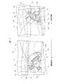
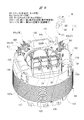
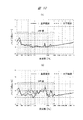
図1はブラシレスモータのワイパ装置への適用例を示す概要図を、図2は図1のDR側ワイパモータを出力軸側から見た斜視図を、図3はDR側ワイパモータの回転軸の軸方向に沿う断面図を、図4はハウジング内の詳細を示す斜視図(ギヤカバー無し)を、図5はギヤカバーの内側を示す分解斜視図を、図6はステータをターミナルホルダ側から見た斜視図を、図7はターミナルホルダの内側を示す斜視図を、図8(a)はチョークコイル有りの回路の概要図,(b)はチョークコイル無しの回路の概要図を、図9はDR側ワイパモータの電源部および駆動部を含む回路図を、図10(a)はチョークコイル有りのノイズ波形グラフ,(b)はチョークコイル無しのノイズ波形グラフをそれぞれ示している。 1 is a schematic view showing an example of application of a brushless motor to a wiper device, FIG. 2 is a perspective view of the DR-side wiper motor of FIG. 1 viewed from the output shaft side, and FIG. 3 is an axial direction of a rotary shaft of the DR-side wiper motor. 4 is a perspective view (without a gear cover) showing details of the inside of the housing, FIG. 5 is an exploded perspective view showing the inside of the gear cover, and FIG. 6 is a perspective view of the stator viewed from the terminal holder side. 7 is a perspective view showing the inside of the terminal holder, FIG. 8A is a schematic diagram of a circuit with a choke coil, FIG. 8B is a schematic diagram of a circuit without a choke coil, and FIG. 10A is a circuit diagram including a power supply unit and a drive unit, and FIG. 10A is a noise waveform graph with a choke coil, and FIG. 10B is a noise waveform graph without a choke coil.
図1に示すように、自動車等の車両10の前方側には、ウィンドシールドとしてのフロントガラス11が設けられている。フロントガラス11の前端部側(図中下側)で、かつ車両10の車幅方向(図中左右方向)に沿う運転席側および助手席側には、それぞれDR側ワイパ装置20およびAS側ワイパ装置30が搭載されている。このように、本実施の形態に係るワイパ装置は、運転席側および助手席側にそれぞれワイパ装置を備えた対向払拭式ワイパ装置を採用している。ここで、DR側は運転席側を、AS側は助手席側をそれぞれ示している。
As shown in FIG. 1, a
DR側ワイパ装置20およびAS側ワイパ装置30は、それぞれ駆動源としてのDR側ワイパモータ21およびAS側ワイパモータ31を備えている。各ワイパモータ21,31は、フロントガラス11上に設けられたDR側ワイパアーム22およびAS側ワイパアーム32(詳細図示せず)を、それぞれ所定の揺動角度で揺動駆動する。これにより、各ワイパアーム22,32の先端部にそれぞれ設けた各ワイパブレード(図示せず)が、フロントガラス11上を往復払拭動作し、ひいてはフロントガラス11に付着した雨水等の付着物を払拭して良好な視界が確保される。
The DR-
車両10の前方側で、かつフロントガラス11の前端部分の近傍には、車両10の車体を形成するカウルトップパネル12が設けられている。カウルトップパネル12は、車両10のDR側とAS側との間、つまり車両10の左右方向を横切るようにして延びている。また、車両10のDR側およびAS側には、車両10の前後方向(図中上下方向)に延び、かつ車体を形成するフロントサイドメンバー13がそれぞれ設けられている。さらに、カウルトップパネル12の前方側には、ダッシュパネルアッパー14が設けられている。このダッシュパネルアッパー14においても、カウルトップパネル12と同様に、車両10の左右方向を横切るようにして延びている。
A cowl
DR側ワイパ装置20は、ダッシュパネルアッパー14に溶接等により固定されたDR側第1ねじ固定部14aと、DR側のフロントサイドメンバー13に溶接等により固定されたDR側第2ねじ固定部13a、DR側第3ねじ固定部13bに固定されている。これに対し、AS側ワイパ装置30は、ダッシュパネルアッパー14に溶接等により固定されたAS側第1ねじ固定部14bと、AS側のフロントサイドメンバー13に溶接等により固定されたAS側第2ねじ固定部13cと、AS側のフロントサイドメンバー13およびカウルトップパネル12の双方に溶接等により固定されたAS側第3ねじ固定部12aに固定されている。
The DR-
このように、DR側ワイパ装置20およびAS側ワイパ装置30は、車両10の車体にそれぞれ3点支持で固定されている。なお、DR側ワイパモータ21およびAS側ワイパモータ31は、図1に示すようにそれぞれ同じものを用いている。そして、各ワイパモータ21,31は、それぞれ3つの取付部a,b,cを備えており、各取付部a,b,cは、それぞれ固定ボルト(図示せず)を介して車体に固定されている。
As described above, the DR-
各ワイパモータ21,31は、それぞれ同じものであるため、以下、DR側ワイパモータ21を代表して、その詳細構造について図面を用いて説明する。
Since the
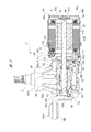
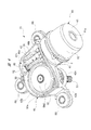
図2ないし図5に示すように、DR側ワイパモータ(ブラシレスモータ)21は、アルミニウム製のハウジング40、プラスチック等よりなる樹脂製のモータカバー60およびギヤカバー80を備えている。これらのハウジング40、モータカバー60およびギヤカバー80は、互いに複数の締結ねじS(図2では2つのみ示す)によって互いに連結されている。
As shown in FIGS. 2 to 5, the DR-side wiper motor (brushless motor) 21 includes a
ここで、ハウジング40とモータカバー60との間、およびハウジング40とギヤカバー80との間には、それぞれブチルゴム等のシール剤やOリング等のシール部材(図示せず)が設けられている。これにより、DR側ワイパモータ21の内部への雨水等の進入が防止される。
Here, a sealant such as butyl rubber and a seal member (not shown) such as an O-ring are provided between the
ハウジング40は、溶融したアルミ材料を鋳造成形等することで所定形状に形成され、モータ収容部41と減速機構収容部42とを備えている。モータ収容部41は、図3に示すように有底筒状に形成されている。モータ収容部41の軸方向一側(図3中右側)は開口されており、当該開口部分は、モータカバー60によって閉塞されている。
The
これに対し、モータ収容部41の軸方向他側(図3中左側)には、環状底部41aが設けられ、当該環状底部41aの中心部分には、回転軸46が回転自在に貫通される第1貫通孔41bが形成されている。また、環状底部41aの第1貫通孔41bからギヤカバー80側(図3中下側)にオフセットした部分には、ターミナルホルダ100の端子保持部106(図6参照)が貫通される第2貫通孔41cが形成されている。
On the other hand, an
モータ収容部41の内側には、環状の段差部43が設けられている。段差部43は、環状の底壁43aと筒状の側壁43bとから構成されている。そして、段差部43の内側には、ステータ(固定子)44が固定されている。ステータ44は、磁性体よりなる複数の鋼板44aを積層して互いに接着することで略円筒形状に形成されている。ステータ44の外周部の軸方向に沿う減速機構収容部42側の略1/4が、モータ収容部41の内周部を形成する側壁43bに圧入され、これにより両者は強固に固定されている。なお、ステータ44の外周部と側壁43bの内周部との間には、図示しない凹凸係合部が設けられている。これによりDR側ワイパモータ21の駆動時において、ステータ44がハウジング40に対して相対回転することが無い。
An
ステータ44の軸方向両側には、絶縁体である樹脂製のコイルボビン44bが突出して設けられている。コイルボビン44bには、U相,V相,W相(3相)のコイル44cが所定の巻き数で巻装されている。これらのU相,V相,W相のコイル44cにおける端部(図示せず)は、スター結線(Y結線)の巻き方となるように電気的に接続されている。ただし、各コイル44cの結線方法としては、スター結線に限らず、例えばデルタ結線(三角結線)等、他の結線方法を採用しても良い。
On both sides of the
なお、ステータ44の径方向内側には、コイルボビン44bを介してコイル44cが巻装された6つのティース(図示せず)が一体に設けられ、これらのティースはステータ44の周方向に等間隔(60度間隔)で配置されている。また、隣り合うティースの間には、コイル44cが配置される6つのスロット(図示せず)が設けられている。
In addition, six teeth (not shown) around which a
そして、各コイル44cは、モータ収容部41の内部でかつ減速機構収容部42寄りに配置されたターミナルホルダ100(図3参照)を介して、ギヤカバー80の内側に固定されかつ減速機構収容部42の内部に配置された制御基板90に電気的に接続されている。各コイル44cには、制御基板90に設けられたFETモジュール96から、所定のタイミングで駆動電流が供給される。これにより、ステータ44に電磁力が発生して、当該ステータ44の内側にあるロータ45が、所定の回転方向に所定の駆動力で回転駆動される。
Each of the
ステータ44の径方向内側には、所定の隙間(エアギャップ)を介してロータ(回転子)45が回転自在に設けられている。ロータ45は、磁性体である複数の鋼板(図示せず)を積層して互いに接着することで略円柱形状に形成されている。そして、ロータ45の径方向外側の表面には、略円筒形状に形成された永久磁石45aが装着されている。このように、ステータ44およびロータ45は、それぞれモータ収容部41の内部に収容されている。
A rotor (rotor) 45 is rotatably provided radially inside the
永久磁石45aは、ロータ45の回転方向に沿って磁極(N極およびS極)が交互に配置されるように4極に着磁されている。このように、DR側ワイパモータ21は、ロータ45の表面に永久磁石45aが装着されたSPM(Surface Permanent Magnet)構造のブラシレスモータを採用している。ただし、SPM構造のブラシレスモータに限らず、ロータ45に複数の永久磁石を埋め込んだIPM(Interior Permanent Magnet)構造のブラシレスモータを採用しても良い。また、略円筒形状の1つの永久磁石45aに換えて、ロータ45の軸線と交差する方向の断面形状が略円弧形状に形成された4つの永久磁石を、ロータ45の周方向に沿って磁極が交互に配置されるように等間隔で設けたものを採用しても良い。
The
ここで、本実施の形態のDR側ワイパモータ21においては、ステータ44,コイルボビン44b,コイル44c,ロータ45,永久磁石45aおよび回転軸46によって、モータ部を構成している。
Here, in the DR-
図3および図4に示すように、ロータ45の軸心には、回転軸46の軸方向一側が固定されている。また、回転軸46の軸方向他側には、転造加工等により形成された螺旋状の歯部46aを備えたウォーム46bが一体に設けられている。ここで、回転軸46に設けられるウォーム46bは、第1貫通孔41bよりも減速機構収容部42側に配置され、ウォーム46bに噛み合うウォームホイール50とともに減速機構SDを構成している。
As shown in FIGS. 3 and 4, one axial side of the
回転軸46の軸方向に沿うロータ45とウォーム46bとの間には、第1ボールベアリング47が設けられている。第1ボールベアリング47の径方向内側は、回転軸46に止め輪やカシメ等の固定手段(図示せず)によって固定されている。一方、第1ボールベアリング47の径方向外側は、減速機構収容部42のモータ収容部41寄りの部分にある第1軸受装着部48に装着されている。なお、第1ボールベアリング47は、第1軸受装着部48に対して、弾性を有するストッパ部材48aにより押圧されて固定されている。
A
また、図4に示すように、回転軸46の軸方向他側には、第1ボールベアリング47と同様に構成された第2ボールベアリング49が装着されている。ただし、第2ボールベアリング49は、第1ボールベアリング47よりも小型のボールベアリングを採用している。ここで、第1ボールベアリング47は、回転軸46を回転自在に支持し、かつ回転軸46を軸方向に移動不能に支持する機能を有するため、大型として頑丈にしている。これに対し、第2ボールベアリング49は、回転軸46の軸方向他側の回転振れを抑制する機能のみを有するため、小型で十分に対応可能となっている。なお、DR側ワイパモータ21の仕様(低速回転型や低減速比型等)によっては、第2ボールベアリング49を省略することもできる。
As shown in FIG. 4, a second ball bearing 49 having the same configuration as the
図2ないし図4に示すように、減速機構収容部42は、有底の略バスタブ形状に形成されている。減速機構収容部42は、底部42aおよび当該底部42aを囲うようにして側壁42bが設けられている。また、側壁42bの底部42a側とは反対側(図4中上側)には開口部42cが設けられている。底部42aおよび開口部42cは、ウォームホイール50の軸方向に対向しており、開口部42cは、ギヤカバー80(図5参照)によって密閉される。
As shown in FIGS. 2 to 4, the speed reduction
減速機構収容部42の底部42aには、減速機構収容部42の外部(図2および図3中上側)に向けて突出されたボス部42dが一体に設けられている。また、減速機構収容部42の側壁42bには、ボス部42dを中心に放射状に突出された3つの取付脚(固定脚)42eが一体に設けられている。これらの取付脚42eには、固定ボルト(図示せず)が貫通するゴムブッシュRBがそれぞれ装着されている。
A
これにより、DR側ワイパモータ21は、各ゴムブッシュRBを介して車両10(図1参照)に固定され、各ゴムブッシュRBが緩衝部材として機能する。よって、DR側ワイパモータ21を車両10に固定した際に、DR側ワイパモータ21の振動が車両10に伝達され難くなって静粛性が向上する。また、これとは逆に、車両10の振動もDR側ワイパモータ21に伝達され難くなり、DR側ワイパモータ21を振動から保護することができる。
Thus, the DR-
図3および図4に示すように、減速機構収容部42の内部には、ウォームホイール50が回転自在に収容されている。ウォームホイール50は、例えばPOM(ポリアセタール)プラスチック等により略円板状に形成され、外周部分にはギヤ歯(歯部)50aが形成されている。そして、ウォームホイール50のギヤ歯50aには、ウォーム46bの歯部46aが噛み合わされている。
As shown in FIGS. 3 and 4, a
ウォームホイール50の回転中心には、出力軸51の軸方向一側が固定されており、当該出力軸51は、減速機構収容部42のボス部42dにより回転自在に支持されている。出力軸51の軸方向他側は、減速機構収容部42の外部に延在しており、出力軸51の軸方向他端部には、DR側ワイパアーム22(図1参照)の基端部が固定されている。これにより、出力軸51はロータ45(図3参照)によって回転される。具体的には、ロータ45(回転軸46)の回転速度が減速機構SDによって減速され、減速されて高トルク化された回転力が、出力軸51から外部のDR側ワイパアーム22に伝達される。このように、減速機構SDは、ロータ45の回転を減速して、減速されて高トルク化された回転力をDR側ワイパアーム22に伝達するものであり、減速機構収容部42は、ロータ45の回転を減速する減速機構SDを収容している。
One axial side of the
図4に示すように、減速機構収容部42の側壁42bには、第2軸受装着部52が設けられている。第2軸受装着部52は第1軸受装着部48(図3参照)と同軸上に配置され、第2軸受装着部52の内部には、第2ボールベアリング49が収容されている。ここで、第2ボールベアリング49の第2軸受装着部52への装着は、第2ボールベアリング49を回転軸46の軸方向他側に装着した状態のもとで、第2ボールベアリング49を第1貫通孔41bと第1軸受装着部48とを通過させることにより行われる。
As shown in FIG. 4, a second
なお、第2ボールベアリング49は、第2軸受装着部52に対して、圧入嵌合させるのでは無く、若干のクリアランスを持って遊嵌させている。これにより、例えば、ハウジング40の製造時等において、第1軸受装着部48と第2軸受装着部52とが若干軸ズレを起こした場合であっても、回転軸46の回転抵抗が増大するようなことが無い。
The second ball bearing 49 is loosely fitted to the second
ここで、本実施の形態のDR側ワイパモータ21においては、ウォーム46b,ウォームホイール50および出力軸51によって、減速機構部を形成している。
Here, in the DR-
図2ないし図4に示すように、モータカバー60は、モータ収容部41の開口部分を、ロータ45の軸方向から閉塞している。具体的には、モータカバー60は有底筒状に形成され、略円盤状に形成された底部61と、当該底部61を囲うようにして設けられた筒状壁部62とを備えている。底部61の中心部分には、底部61の強度を高めて撓み難くするための凹凸部61aが設けられている。これにより、DR側ワイパモータ21の作動時に、モータカバー60が振動するのを抑制して、静粛性を向上させることができる。
As shown in FIGS. 2 to 4, the
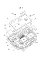
図5に示すように、ギヤカバー80は、減速機構収容部42の開口部42c(図4参照)を密閉するもので、開口部42cと同様の外郭形状をなしている。ギヤカバー80は、底壁部81および側壁部82を備えている。ギヤカバー80の内側で、かつ底壁部81には、第1固定ねじSC1によって制御基板(制御部)90が固定されている。
As shown in FIG. 5, the gear cover 80 seals the
また、ギヤカバー80の側壁部82には、車両10側の外部コネクタ(図示せず)が接続されるコネクタ接続部82aが一体に設けられている。ギヤカバー80の底壁部81には、5つの第1導電部材CM1および3つの第2導電部材CM2がそれぞれインサート成形により設けられている。
Further, a
コネクタ接続部82aの内側には、第1導電部材CM1の一端側の端子(図示せず)がそれぞれ露出されている。一方、複数の第1導電部材CM1の他端側の端子TM1は、制御基板90にそれぞれ電気的に接続される。なお、車両10側の外部コネクタには、車載バッテリやワイパスイッチ(図示せず)が電気的に接続されている。
Terminals (not shown) on one end side of the first conductive member CM1 are exposed inside the
第2導電部材CM2の一端側の端子TM2は、制御基板90にそれぞれ電気的に接続される。一方、第2導電部材CM2の他端側の端子TM3は、ターミナルホルダ100の端子保持部106に設けられた第1メス型端子107,第2メス型端子108,第3メス型端子109(図6参照)にそれぞれ電気的に接続される。つまり、第2導電部材CM2は、ステータ44に巻装されたコイル44c(図3参照)のU相,V相,W相の3相に合わせて3つ設けられている。
The terminals TM2 on one end side of the second conductive member CM2 are electrically connected to the
図5に示すように、制御基板90は、ギヤカバー80の底壁部81側とは反対側、つまり回転軸46および出力軸51がある側(図中上側)に向けられる第1面91と、ギヤカバー80の底壁部81側、つまり第1面91側とは反対側(図中下側)に向けられる第2面92とを備えている。
As shown in FIG. 5, the
制御基板90の第1面91には、DR側ワイパモータ21を統括的に制御するCPU93と、回転軸46に設けたセンサマグネットSM1(図3参照)と対向する第1ホールIC94a,第2ホールIC94b,第3ホールIC94cと、ウォームホイール50に設けたセンサマグネットSM2(図4参照)と対向するMRセンサ95とが設けられている。
On the
これに対し、制御基板90の第2面92には、駆動系の電子部品であるFETモジュール96と、他の電子部品であるキャパシタCPとが設けられている。ここで、FETモジュール96は、3相の各コイル44c(図3参照)への通電状態を高速で切り替える複数のスイッチング素子(図9参照)により構成されている。したがって、FETモジュール96は発熱し易くなっている。よって、FETモジュール96の放熱性を向上させるために、当該FETモジュール96は、熱伝導部材97aおよび熱伝導シート97bを介してハウジング40(図3参照)に接続されている。
On the other hand, on the
なお、図5に示すように、FETモジュール96は、制御基板90をギヤカバー80の底壁部81に装着する前に、一対の第2固定ねじSC2によってギヤカバー80の底壁部81に固定される。その後、FETモジュール96は、はんだ付け等の接続手段によって、制御基板90の第2面92に実装される。
As shown in FIG. 5, before mounting the
ここで、CPU93およびFETモジュール96は、DR側ワイパモータ21に駆動電流を供給して、ロータ45(図3参照)の回転を制御するようになっている。そして、CPU93は、各ホールIC94a,94b,94cおよびMRセンサ95で検出された検出値(矩形波信号)に基づいて、FETモジュール96を制御する。これにより、ロータ45の回転状態が制御される。
Here, the
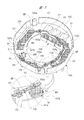
図3,図6,図7に示すように、ステータ44の軸方向一側(図3中左側)、つまりステータ44の軸方向に沿う減速機構収容部42側には、プラスチック等の樹脂材料により環状に形成されたターミナルホルダ(ホルダ部材)100が設けられている。ターミナルホルダ100は、ステータ44の軸方向一側にあるコイルボビン44bを覆うようにして設けられ、環状の本体部101と、当該本体部101からステータ44の軸方向に延在された筒状壁部102とを備えている。
As shown in FIGS. 3, 6, and 7, one side of the
ここで、筒状壁部102には、コイルボビン44bに設けられた係合凹部(図示せず)に対して、径方向外側から係合する3つの係合爪102a(図7参照)が一体に設けられている。これらの係合爪102aは、筒状壁部102の周方向に所定間隔で分散して配置されている。これにより、3つの係合爪102aをコイルボビン44bの係合凹部にそれぞれ係合させることで、ターミナルホルダ100をステータ44に対してがたつくこと無く安定して固定することができる。
Here, three engaging
本体部101には、断面が略U字形状に形成された第1素子収容部103,第2素子収容部104,第3素子収容部105が一体に設けられている。これらの第1素子収容部103,第2素子収容部104,第3素子収容部105は、本発明における素子保持部を構成しており、本体部101の減速機構収容部42側(図6中上側)に向けて突出され、本体部101のステータ44側(図7中上側)が開口されている。つまり、第1素子収容部103,第2素子収容部104,第3素子収容部105には、本体部101のステータ44側から、雑防素子としてのU相用チョークコイルCU,V相用チョークコイルCV,W相用チョークコイルCWがそれぞれ収容されるようになっている。
The
なお、第1素子収容部103,第2素子収容部104,第3素子収容部105に保持されるU相用チョークコイルCU,V相用チョークコイルCV,W相用チョークコイルCWは、何れも同じ仕様のものが用いられ、DR側ワイパモータ21の作動時に発生する電気ノイズの外部への放射を抑制するものである。
The U-phase choke coil CU, the V-phase choke coil CV, and the W-phase choke coil CW held in the first
第1素子収容部103,第2素子収容部104,第3素子収容部105は、ステータ44の軸方向から見たときに、略長方形形状に形成されている。そして、第1素子収容部103,第2素子収容部104,第3素子収容部105の長手方向が、本体部101の周方向に向くようにして、それぞれ所定間隔で並べられている。具体的には、第1素子収容部103および第2素子収容部104は、互いに180度間隔で対向するように本体部101に配置されている。第3素子収容部105は、本体部101の周方向に沿う第1素子収容部103と第2素子収容部104との間に配置され、第1素子収容部103および第2素子収容部104の双方に対して、略90度間隔となるように配置されている。
The
ここで、第1素子収容部103,第2素子収容部104,第3素子収容部105は、本体部101の減速機構収容部42側に向けて突出されており、これにより、図3に示すように、モータ収容部41の環状底部41aにある比較的大きなデッドスペースDSに配置される。したがって、DR側ワイパモータ21が大型化するのを抑制することができる。
Here, the first
また、本体部101の周方向に沿う第1素子収容部103と第2素子収容部104との間で、かつ第3素子収容部105が配置されていない側には、略直方体形状の端子保持部106が一体に設けられている。端子保持部106は、第1素子収容部103,第2素子収容部104,第3素子収容部105と同じ方向に突出している。つまり、端子保持部106は、本体部101の減速機構収容部42側に向けて突出している。
Further, between the first
端子保持部106の内側には、接続端子としての第1メス型端子107,第2メス型端子108,第3メス型端子109が保持されている。第1メス型端子107,第2メス型端子108,第3メス型端子109は、ターミナルホルダ100の径方向外側(図6中手前側)に開口されている。そして、第1メス型端子107,第2メス型端子108,第3メス型端子109には、3つの第2導電部材CM2の端子TM3(図5参照)がそれぞれ差し込まれて電気的に接続されるようになっている。なお、端子保持部106には、第1メス型端子107,第2メス型端子108,第3メス型端子109に対する端子TM3の差し込みを案内する差し込み案内テーパ部TPが設けられている。このように、端子保持部106を有する本体部101は、第1メス型端子107,第2メス型端子108,第3メス型端子109を保持するようになっている。
Inside the
第1メス型端子107,第2メス型端子108,第3メス型端子109には、溶接やかしめ等によって、U相用チョークコイルCU,V相用チョークコイルCV,W相用チョークコイルCWの他端が電気的に接続されている。そして、図7に示すように、端子保持部106のステータ44側にも、U相用チョークコイルCU,V相用チョークコイルCV,W相用チョークコイルCWの他端の端子保持部106への差し込みをそれぞれ案内する差し込み案内テーパ部TPが設けられている。
The first
図6に示すように、本体部101の減速機構収容部42側で、かつ本体部101の周方向に沿う第1素子収容部103と第3素子収容部105との間には、接続部材としてのU相用接続部材MUおよびW相用接続部材MWが設けられている。ただし、U相用接続部材MUは第1素子収容部103寄りに配置され、W相用接続部材MWは第3素子収容部105寄りに配置されている。また、本体部101の減速機構収容部42側で、かつ本体部101の周方向に沿う第3素子収容部105と第2素子収容部104との間には、接続部材としてのV相用接続部材MVが設けられている。
As shown in FIG. 6, a connection member is provided between the
ここで、U相用接続部材MU,V相用接続部材MV,W相用接続部材MWは、それぞれ黄銅等の導電性に優れた板材をプレス成形等することにより所定形状に形成されている。U相用接続部材MU,V相用接続部材MV,W相用接続部材MWは何れも同じ形状であるため、図6の右上の破線で示した接続部材Mを代表して、その構造について説明する。接続部材Mは、本体部101に差し込み固定される固定本体部M1と、U相〜W相のコイル44cの端部と、U相用〜W相用チョークコイルCU〜CWの一端とを電気的に接続する接続本体部M2とを備えている。
Here, the U-phase connection member MU, the V-phase connection member MV, and the W-phase connection member MW are each formed into a predetermined shape by press-molding a plate material having excellent conductivity such as brass or the like. Since the U-phase connection member MU, the V-phase connection member MV, and the W-phase connection member MW all have the same shape, the structure will be described as a representative of the connection member M shown by the broken line in the upper right of FIG. I do. The connection member M electrically connects the fixed main body M1 inserted and fixed to the
そして、破線矢印(1)に示すように、固定本体部M1に設けた爪状の先端側を本体部101に臨ませて、固定本体部M1を本体部101の差し込み部101a(図7参照)に差し込み、その後、固定本体部M1に設けた爪状の先端側を破線矢印(2)に示すように屈曲させる。これにより、接続部材Mは本体部101に固定される。一方、接続部材Mを本体部101に固定することで、接続本体部M2は、本体部101に形成された導線挿通孔101b(図7参照)に対して、ターミナルホルダ100の軸方向から対向される。これにより、導線挿通孔101bに挿通された、U相〜W相のコイル44cの端部と、U相用〜W相用チョークコイルCU〜CWの一端(図6参照)とが、略U字形状に形成された接続本体部M2の内側に配置される。そして、この状態で接続本体部M2をかしめることで、U相〜W相のコイル44cの端部と、U相用〜W相用チョークコイルCU〜CWの一端とが、接続本体部M2の内側で電気的に接続される。
Then, as shown by the dashed arrow (1), the claw-shaped distal end provided on the fixed main body M1 faces the
なお、図7に示すように、導線挿通孔101bのステータ44側にも、U相〜W相のコイル44cの端部およびU相用〜W相用チョークコイルCU〜CWの一端の導線挿通孔101bへの差し込みをそれぞれ案内する差し込み案内テーパ部TPが設けられている。このように、導線挿通孔101bを有する本体部101は、U相〜W相のコイル44cの端部を保持するようになっている。
As shown in FIG. 7, the end of the U-phase to W-
ここで、図6に示すように、U相用接続部材MUは、U相のコイル44cの端部とU相用チョークコイルCUの一端を、本体部101の減速機構収容部42側で電気的に接続し、V相用接続部材MVは、V相のコイル44cの端部とV相用チョークコイルCVの一端を、本体部101の減速機構収容部42側で電気的に接続し、W相用接続部材MWは、W相のコイル44cの端部とW相用チョークコイルCWの一端を、本体部101の減速機構収容部42側で電気的に接続している。
Here, as shown in FIG. 6, the U-phase connecting member MU electrically connects the end of the
このように、本体部101の減速機構収容部42側において、U相〜W相のコイル44cの端部と、U相用〜W相用チョークコイルCU〜CWの一端との電気的な接続作業が行われるため、DR側ワイパモータ21の組み立て作業性の低下が抑制される。また、それぞれの接続部材Mの接続本体部M2は、本体部101の周方向に沿う第1素子収容部103,第2素子収容部104,第3素子収容部105の間に配置されるので、DR側ワイパモータ21の大型化が抑制される。
As described above, on the side of the speed reduction
図7に示すように、本体部101のステータ44側には、U相用〜W相用チョークコイルCU〜CWの一端側および他端側を保持する複数の保持溝GRが設けられている。これにより、U相用〜W相用チョークコイルCU〜CWの一端側および他端側が、ステータ44側に突出するのを抑制して、ひいてはDR側ワイパモータ21の大型化を抑制している。また、U相用〜W相用チョークコイルCU〜CWの一端側および他端側を、保持溝GRにそれぞれ保持させることで、ターミナルホルダ100に対するU相用〜W相用チョークコイルCU〜CWのがたつきが抑制される。
As illustrated in FIG. 7, a plurality of holding grooves GR that hold one end and the other end of the U-phase to W-phase choke coils CU to CW are provided on the
複数の保持溝GRには、U相用〜W相用チョークコイルCU〜CWの一端側および他端側の保持溝GRからの脱落を防止する複数の保持爪KC(図7の破線円参照)が設けられている。また、第1素子収容部103,第2素子収容部104,第3素子収容部105の開口部分には、U相用〜W相用チョークコイルCU〜CWの第1素子収容部103,第2素子収容部104,第3素子収容部105からの脱落を防止する保持突起103a,104a,105aがそれぞれ設けられている。これにより、図6に示すように、ステータ44を下方に配置し、かつターミナルホルダ100を上方から装着する場合において、ターミナルホルダ100からU相用〜W相用チョークコイルCU〜CWが脱落するのを確実に防止して、DR側ワイパモータ21の組み立て性を向上させている。
A plurality of holding claws KC for preventing the U-phase to W-phase choke coils CU to CW from dropping from the holding grooves GR on one end side and the other end side are provided in the plurality of holding grooves GR (see the broken circle in FIG. 7). Is provided. Further, the opening portions of the first
次に、以上のように形成したDR側ワイパモータ21の電気回路について、図面を用いて詳細に説明する。
Next, the electric circuit of the DR-
ターミナルホルダ100の部分における電気回路は、図8(a)に示すように形成されている。具体的には、一対のU相〜W相のコイル44cの端部のそれぞれが、導線挿通孔101b(図7参照)を介してそれぞれ外部に引き出されて、U相用接続部材MU,V相用接続部材MV,W相用接続部材MWに接続されている。また、U相用接続部材MU,V相用接続部材MV,W相用接続部材MWには、U相用〜W相用チョークコイルCU〜CWの一端が接続されている。そして、U相用〜W相用チョークコイルCU〜CWの他端は、端子保持部106に設けられた第1メス型端子107,第2メス型端子108,第3メス型端子109にそれぞれ接続されている。
The electric circuit in the
ここで、本実施の形態に係るターミナルホルダ100は、U相用〜W相用チョークコイルCU〜CWを備えない従前の仕様のDR側ワイパモータにも対応可能となっている。具体的には、ターミナルホルダ100の部分の電気回路を、図8(b)に示すように形成するようにする。
Here, the
すなわち、図8(a)に示す状態から、U相用〜W相用チョークコイルCU〜CWを取り除く。具体的には、図7の第1素子収容部103,第2素子収容部104,第3素子収容部105から、それぞれU相用〜W相用チョークコイルCU〜CWを取り除く。そして、各導線挿通孔101b(図7参照)に配置された一対のU相〜W相のコイル44cの端部のそれぞれを、端子保持部106のステータ44側から差し込んで、第1メス型端子107,第2メス型端子108,第3メス型端子109にそれぞれ接続するようにする。これにより、図8(b)に示すような電気回路を形成することができる。ここで、図8(b)においては、図8(a)に比して、第2メス型端子108と第3メス型端子109との位置関係が逆になっているが、後述する図9に示すスイッチング素子SU1,SU2,SV1,SV2,SW1,SW2の制御タイミングを切り換えることで、図8(a)に示すものと同様に制御可能である。
That is, the U-phase to W-phase choke coils CU to CW are removed from the state shown in FIG. Specifically, the U-phase to W-phase choke coils CU to CW are removed from the
このように、本実施の形態に係るターミナルホルダ100においては、U相用〜W相用チョークコイルCU〜CW無しのDR側ワイパモータと、U相用〜W相用チョークコイルCU〜CW有りのDR側ワイパモータ21とで、共通化を図ることができる。
As described above, in the
DR側ワイパモータ21の全体の電気回路は、図9に示すように形成され、具体的には、電源部と駆動部とノイズ除去部とモータ部とを備えている。電源部は、突入電流の発生等を防ぐために、抵抗RおよびコンデンサCを備え、かつバッテリ等の電源に接続されるプラス(+)端子およびマイナス(−)端子を備えている。駆動部は、U相,V相,W相(3相)の駆動回路を形成し、合計6つのスイッチング素子SU1,SU2,SV1,SV2,SW1,SW2が設けられている。また、ノイズ除去部には、合計3つのU相用チョークコイルCU,V相用チョークコイルCV,W相用チョークコイルCWが設けられている。さらに、モータ部には、U相〜W相のコイル44cが巻装されたステータ44が設けられている。
The entire electric circuit of the DR-
このように、U相用〜W相用チョークコイルCU〜CWよりなる「ノイズ除去部」は、「駆動部」と「モータ部」との間に配置されている。これにより、図10に示すようなノイズ除去効果を発揮することができる。図10(a)は、U相用〜W相用チョークコイルCU〜CW有りのDR側ワイパモータ21のノイズ波形グラフを、図10(b)は、U相用〜W相用チョークコイルCU〜CW無しのDR側ワイパモータのノイズ波形グラフを、それぞれ示している。
As described above, the “noise removing unit” including the U-phase to W-phase choke coils CU to CW is disposed between the “drive unit” and the “motor unit”. Thereby, a noise removing effect as shown in FIG. 10 can be exhibited. 10A is a noise waveform graph of the DR-
図10(a)に示すように、本実施の形態に係るDR側ワイパモータ21によれば、U相用〜W相用チョークコイルCU〜CWを備えないもの(図10(b)参照)に比して、特に、UHF帯における放射ノイズ(電気ノイズ)のレベルを低減できることが判明した。これにより、特にノイズ対策の基準が厳しい欧州車向けのワイパモータに適用可能となり、部品を共通化させてワイパモータのバリエーションを増やしつつ、十分な信頼性の向上が図れるようになる。
As shown in FIG. 10 (a), according to the DR-
以上詳述したように、本実施の形態によれば、ステータ44の軸方向一側に、ステータ44に巻装されたコイル44cの端部および制御基板90に接続される第1メス型端子107,第2メス型端子108,第3メス型端子109を保持するターミナルホルダ100が設けられ、ターミナルホルダ100に、電気ノイズの外部への放射を抑制するU相用チョークコイルCU,V相用チョークコイルCV,W相用チョークコイルCWを保持する第1素子収容部103,第2素子収容部104,第3素子収容部105が設けられるので、DR側ワイパモータ21の制御基板90のサイズアップが抑えられ、かつ電気ノイズの外部への放射をより抑えることが可能となる。
As described in detail above, according to the present embodiment, the first
また、既存のDR側ワイパモータ(U相用〜W相用チョークコイルCU〜CWを備えないもの)を形成するコイル44cの端部と第1メス型端子107,第2メス型端子108,第3メス型端子109との間にU相用〜W相用チョークコイルCU〜CWを配置できるので(図8参照)、部品点数の増加をU相用〜W相用チョークコイルCU〜CWのみとして、組み立て性低下を抑えて歩留まりを向上させることができる。
Also, the end of the
さらに、U相用〜W相用チョークコイルCU〜CWを省略してコイル44cの端部と第1メス型端子107,第2メス型端子108,第3メス型端子109とを直接接続(図8(b)参照)すれば、従前のDR側ワイパモータを形成することができる。すなわち、U相用〜W相用チョークコイルCU〜CW無しのDR側ワイパモータと、U相用〜W相用チョークコイルCU〜CW有りのDR側ワイパモータ21とで、ターミナルホルダ100の共通化を図ることができる。
Furthermore, the choke coils CU to CW for U-phase to W-phase are omitted, and the end of the
本発明は上記実施の形態に限定されるものではなく、その要旨を逸脱しない範囲で種々変更可能であることは言うまでもない。例えば、上記実施の形態においては、DR側ワイパモータ21を、フロントガラス11上を揺動するDR側ワイパアーム22を駆動するものとしたが、本発明はこれに限らず、リヤガラス上を揺動するワイパアームを駆動するものにも採用することができる。
The present invention is not limited to the above embodiment, and it goes without saying that various changes can be made without departing from the scope of the invention. For example, in the above embodiment, the DR-
さらに、上記実施の形態においては、本発明に係るブラシレスモータを、ワイパ装置の駆動源に適用したものを示したが、本発明はこれに限らず、サンルーフ装置やパワーウィンド装置等、他の装置の駆動源にも適用することができる。 Furthermore, in the above embodiment, the brushless motor according to the present invention is applied to the drive source of the wiper device. However, the present invention is not limited to this, and other devices such as a sunroof device and a power window device may be used. Can be applied to the drive source of
10 車両
11 フロントガラス
12 カウルトップパネル
12a AS側第3ねじ固定部
13 フロントサイドメンバー
13a DR側第2ねじ固定部
13b DR側第3ねじ固定部
13c AS側第2ねじ固定部
14 ダッシュパネルアッパー
14a DR側第1ねじ固定部
14b AS側第1ねじ固定部
20 DR側ワイパ装置
21 DR側ワイパモータ(ブラシレスモータ,駆動源)
22 DR側ワイパアーム
30 AS側ワイパ装置
31 AS側ワイパモータ(ブラシレスモータ,駆動源)
32 AS側ワイパアーム
40 ハウジング
41 モータ収容部
41a 環状底部
41b 第1貫通孔
41c 第2貫通孔
42 減速機構収容部
42a 底部
42b 側壁
42c 開口部
42d ボス部
42e 取付脚
43 段差部
43a 底壁
43b 側壁
44 ステータ(固定子,モータ部)
44a 鋼板
44b コイルボビン(モータ部)
44c コイル(モータ部)
45 ロータ(回転子,モータ部)
45a 永久磁石(モータ部)
46 回転軸(モータ部)
46a 歯部
46b ウォーム(減速機構部)
47 第1ボールベアリング
48 第1軸受装着部
48a ストッパ部材
49 第2ボールベアリング
50 ウォームホイール(減速機構部)
50a ギヤ歯
51 出力軸(減速機構部)
52 第2軸受装着部
60 モータカバー
61 底部
61a 凹凸部
62 筒状壁部
80 ギヤカバー
81 底壁部
82 側壁部
82a コネクタ接続部
90 制御基板(制御部)
91 第1面
92 第2面
93 CPU
94a〜94c 第1〜第3ホールIC
95 MRセンサ
96 FETモジュール
97a 熱伝導部材
97b 熱伝導シート
100 ターミナルホルダ(ホルダ部材)
101 本体部
101a 差し込み部
101b 導線挿通孔
102 筒状壁部
102a 係合爪
103〜105 第1〜第3素子収容部(素子保持部)
103a〜105a 保持突起
106 端子保持部
107〜109 第1〜第3メス型端子(接続端子)
C コンデンサ
CM1,CM2 第1,第2導電部材
CP キャパシタ
CU〜CW U相用〜W相用チョークコイル(雑防素子,チョークコイル)
DS デッドスペース
GR 保持溝
KC 保持爪
M 接続部材
M1 固定本体部
M2 接続本体部
MU〜MW U相用〜W相用接続部材(接続部材)
R 抵抗
RB ゴムブッシュ
S 締結ねじ
SC1,SC2 第1,第2固定ねじ
SD 減速機構
SM1,SM2 センサマグネット
SU1,SU2,SV1,SV2,SW1,SW2 スイッチング素子
TM1,TM2,TM3 端子
TP 差し込み案内テーパ部
a〜c 取付部
DESCRIPTION OF
22 DR
32 AS-
44a Steel plate 44b Coil bobbin (motor part)
44c coil (motor part)
45 Rotor (rotor, motor)
45a permanent magnet (motor part)
46 Rotary axis (motor part)
47
52 Second
91
94a-94c 1st-3rd Hall IC
95
103a to
C capacitor CM1, CM2 First and second conductive members CP capacitor CU to CW U-phase to W-phase choke coil (anti-noise element, choke coil)
DS Dead space GR Holding groove KC Holding claw M Connecting member M1 Fixed main body M2 Connection main body MU to MW U phase to W phase connection member (connection member)
R Resistance RB Rubber bush S Fastening screw SC1, SC2 First and second fixing screw SD Reduction mechanism SM1, SM2 Sensor magnet SU1, SU2, SV1, SV2, SW1, SW2 Switching element TM1, TM2, TM3 Terminal TP Insertion guide taper ac mounting part
Claims (5)
前記回転子の回転を減速する減速機構部と、
前記回転子の回転を制御する制御部と、
を備えたブラシレスモータであって、
前記固定子の軸方向一側に設けられ、前記固定子に巻装されたコイルの端部および前記制御部に接続される接続端子を保持するホルダ部材と、
前記ホルダ部材に設けられ、電気ノイズの外部への放射を抑制する雑防素子を保持する素子保持部と、
を有し、
前記雑防素子はチョークコイルであり、前記チョークコイルの一端が前記コイルの端部に接続され、前記チョークコイルの他端が前記接続端子に接続されている、ブラシレスモータ。 A motor unit having a stator and a rotor,
A reduction mechanism for reducing the rotation of the rotor,
A control unit for controlling the rotation of the rotor,
A brushless motor having
A holder member provided on one axial side of the stator and holding a connection terminal connected to an end of the coil wound on the stator and the control unit;
An element holding unit that is provided on the holder member and holds an anti-noise element that suppresses radiation of electric noise to the outside,
Have a,
The noise suppression device is a choke coil, one end of the choke coil is connected to an end of the coil, the other end of the choke coil is connected for the connection terminals, the brushless motor.
前記ホルダ部材は環状の本体部を備え、前記本体部の周方向に複数の前記素子保持部が並んで設けられている、
ブラシレスモータ。 The brushless motor according to claim 1,
The holder member includes an annular main body, and a plurality of the element holding units are provided side by side in a circumferential direction of the main body.
Brushless motor.
隣り合う前記素子保持部の間に、前記接続端子を保持する端子保持部が設けられている、
ブラシレスモータ。 The brushless motor according to claim 2 ,
A terminal holding unit that holds the connection terminal is provided between the adjacent element holding units,
Brushless motor.
隣り合う前記素子保持部の間に、前記コイルの端部と前記雑防素子とを接続する接続部材が設けられている、
ブラシレスモータ。 The brushless motor according to claim 2 or 3 ,
A connection member that connects an end of the coil and the noise control element is provided between the adjacent element holding units,
Brushless motor.
前記ブラシレスモータは、ワイパ装置の駆動源である、
ブラシレスモータ。 The brushless motor according to any one of claims 1 to 4 ,
The brushless motor is a drive source of a wiper device,
Brushless motor.
Priority Applications (1)
| Application Number | Priority Date | Filing Date | Title |
|---|---|---|---|
| JP2016021616A JP6640586B2 (en) | 2016-02-08 | 2016-02-08 | Brushless motor |
Applications Claiming Priority (1)
| Application Number | Priority Date | Filing Date | Title |
|---|---|---|---|
| JP2016021616A JP6640586B2 (en) | 2016-02-08 | 2016-02-08 | Brushless motor |
Publications (2)
| Publication Number | Publication Date |
|---|---|
| JP2017143595A JP2017143595A (en) | 2017-08-17 |
| JP6640586B2 true JP6640586B2 (en) | 2020-02-05 |
Family
ID=59627621
Family Applications (1)
| Application Number | Title | Priority Date | Filing Date |
|---|---|---|---|
| JP2016021616A Active JP6640586B2 (en) | 2016-02-08 | 2016-02-08 | Brushless motor |
Country Status (1)
| Country | Link |
|---|---|
| JP (1) | JP6640586B2 (en) |
Families Citing this family (3)
| Publication number | Priority date | Publication date | Assignee | Title |
|---|---|---|---|---|
| JP6756313B2 (en) | 2017-07-25 | 2020-09-16 | 株式会社デンソー | Shutter device |
| WO2021192203A1 (en) * | 2020-03-27 | 2021-09-30 | 三菱電機株式会社 | Dynamo-electric machine device and electric power steering device |
| JP2023007626A (en) * | 2021-07-02 | 2023-01-19 | コアレスモータ株式会社 | coreless motor |
Family Cites Families (4)
| Publication number | Priority date | Publication date | Assignee | Title |
|---|---|---|---|---|
| JPS6096158A (en) * | 1983-10-27 | 1985-05-29 | Toshiba Corp | Noise reducing device of rotary electric machine |
| JPH01117663A (en) * | 1987-10-30 | 1989-05-10 | Mitsubishi Electric Corp | Noise filter for inverter |
| JP5410194B2 (en) * | 2009-08-07 | 2014-02-05 | 株式会社デンソー | Motor with built-in drive circuit |
| EP2840700B1 (en) * | 2012-04-16 | 2023-06-14 | Mitsuba Corporation | Wiper apparatus |
-
2016
- 2016-02-08 JP JP2016021616A patent/JP6640586B2/en active Active
Also Published As
| Publication number | Publication date |
|---|---|
| JP2017143595A (en) | 2017-08-17 |
Similar Documents
| Publication | Publication Date | Title |
|---|---|---|
| EP2475079B1 (en) | Wiper motor | |
| JP6545169B2 (en) | Brushless wiper motor and method of assembling the same | |
| CN106663991B (en) | Brushless wiper motor | |
| JP6634372B2 (en) | Brushless wiper motor | |
| US9929624B2 (en) | Brushless motor and wiper apparatus | |
| US10442401B2 (en) | Brushless wiper motor | |
| WO2015045003A1 (en) | Brushless wiper motor | |
| JP6324946B2 (en) | Brushless wiper motor | |
| JP6640586B2 (en) | Brushless motor | |
| JP2013198188A (en) | Brushless motor and wiper device | |
| JP2013223317A (en) | Brushless windshield wiper motor | |
| JP6681490B2 (en) | Brushless wiper motor and wiper device | |
| JP6552422B2 (en) | Brushless motor | |
| JP2017013739A (en) | Support member |
Legal Events
| Date | Code | Title | Description |
|---|---|---|---|
| A621 | Written request for application examination |
Free format text: JAPANESE INTERMEDIATE CODE: A621 Effective date: 20180828 |
|
| A977 | Report on retrieval |
Free format text: JAPANESE INTERMEDIATE CODE: A971007 Effective date: 20190522 |
|
| A131 | Notification of reasons for refusal |
Free format text: JAPANESE INTERMEDIATE CODE: A131 Effective date: 20190528 |
|
| A521 | Written amendment |
Free format text: JAPANESE INTERMEDIATE CODE: A523 Effective date: 20190718 |
|
| TRDD | Decision of grant or rejection written | ||
| A01 | Written decision to grant a patent or to grant a registration (utility model) |
Free format text: JAPANESE INTERMEDIATE CODE: A01 Effective date: 20191203 |
|
| A61 | First payment of annual fees (during grant procedure) |
Free format text: JAPANESE INTERMEDIATE CODE: A61 Effective date: 20191226 |
|
| R150 | Certificate of patent or registration of utility model |
Ref document number: 6640586 Country of ref document: JP Free format text: JAPANESE INTERMEDIATE CODE: R150 |