WO2015045003A1 - Brushless wiper motor - Google Patents
Brushless wiper motor Download PDFInfo
- Publication number
- WO2015045003A1 WO2015045003A1 PCT/JP2013/075712 JP2013075712W WO2015045003A1 WO 2015045003 A1 WO2015045003 A1 WO 2015045003A1 JP 2013075712 W JP2013075712 W JP 2013075712W WO 2015045003 A1 WO2015045003 A1 WO 2015045003A1
- Authority
- WO
- WIPO (PCT)
- Prior art keywords
- magnet
- gear housing
- wiper motor
- output shaft
- sensor
- Prior art date
Links
Images


Classifications
-
- H—ELECTRICITY
- H02—GENERATION; CONVERSION OR DISTRIBUTION OF ELECTRIC POWER
- H02K—DYNAMO-ELECTRIC MACHINES
- H02K7/00—Arrangements for handling mechanical energy structurally associated with dynamo-electric machines, e.g. structural association with mechanical driving motors or auxiliary dynamo-electric machines
- H02K7/10—Structural association with clutches, brakes, gears, pulleys or mechanical starters
- H02K7/116—Structural association with clutches, brakes, gears, pulleys or mechanical starters with gears
- H02K7/1163—Structural association with clutches, brakes, gears, pulleys or mechanical starters with gears where at least two gears have non-parallel axes without having orbital motion
- H02K7/1166—Structural association with clutches, brakes, gears, pulleys or mechanical starters with gears where at least two gears have non-parallel axes without having orbital motion comprising worm and worm-wheel
-
- B—PERFORMING OPERATIONS; TRANSPORTING
- B60—VEHICLES IN GENERAL
- B60S—SERVICING, CLEANING, REPAIRING, SUPPORTING, LIFTING, OR MANOEUVRING OF VEHICLES, NOT OTHERWISE PROVIDED FOR
- B60S1/00—Cleaning of vehicles
- B60S1/02—Cleaning windscreens, windows or optical devices
- B60S1/04—Wipers or the like, e.g. scrapers
- B60S1/06—Wipers or the like, e.g. scrapers characterised by the drive
- B60S1/08—Wipers or the like, e.g. scrapers characterised by the drive electrically driven
-
- H—ELECTRICITY
- H02—GENERATION; CONVERSION OR DISTRIBUTION OF ELECTRIC POWER
- H02K—DYNAMO-ELECTRIC MACHINES
- H02K1/00—Details of the magnetic circuit
- H02K1/06—Details of the magnetic circuit characterised by the shape, form or construction
- H02K1/22—Rotating parts of the magnetic circuit
- H02K1/27—Rotor cores with permanent magnets
- H02K1/2706—Inner rotors
- H02K1/272—Inner rotors the magnetisation axis of the magnets being perpendicular to the rotor axis
- H02K1/274—Inner rotors the magnetisation axis of the magnets being perpendicular to the rotor axis the rotor consisting of two or more circumferentially positioned magnets
- H02K1/2753—Inner rotors the magnetisation axis of the magnets being perpendicular to the rotor axis the rotor consisting of two or more circumferentially positioned magnets the rotor consisting of magnets or groups of magnets arranged with alternating polarity
- H02K1/276—Magnets embedded in the magnetic core, e.g. interior permanent magnets [IPM]
-
- H—ELECTRICITY
- H02—GENERATION; CONVERSION OR DISTRIBUTION OF ELECTRIC POWER
- H02K—DYNAMO-ELECTRIC MACHINES
- H02K1/00—Details of the magnetic circuit
- H02K1/06—Details of the magnetic circuit characterised by the shape, form or construction
- H02K1/22—Rotating parts of the magnetic circuit
- H02K1/27—Rotor cores with permanent magnets
- H02K1/2706—Inner rotors
- H02K1/272—Inner rotors the magnetisation axis of the magnets being perpendicular to the rotor axis
- H02K1/274—Inner rotors the magnetisation axis of the magnets being perpendicular to the rotor axis the rotor consisting of two or more circumferentially positioned magnets
- H02K1/2753—Inner rotors the magnetisation axis of the magnets being perpendicular to the rotor axis the rotor consisting of two or more circumferentially positioned magnets the rotor consisting of magnets or groups of magnets arranged with alternating polarity
- H02K1/278—Surface mounted magnets; Inset magnets
-
- H—ELECTRICITY
- H02—GENERATION; CONVERSION OR DISTRIBUTION OF ELECTRIC POWER
- H02K—DYNAMO-ELECTRIC MACHINES
- H02K11/00—Structural association of dynamo-electric machines with electric components or with devices for shielding, monitoring or protection
- H02K11/20—Structural association of dynamo-electric machines with electric components or with devices for shielding, monitoring or protection for measuring, monitoring, testing, protecting or switching
- H02K11/21—Devices for sensing speed or position, or actuated thereby
- H02K11/215—Magnetic effect devices, e.g. Hall-effect or magneto-resistive elements
-
- H—ELECTRICITY
- H02—GENERATION; CONVERSION OR DISTRIBUTION OF ELECTRIC POWER
- H02K—DYNAMO-ELECTRIC MACHINES
- H02K29/00—Motors or generators having non-mechanical commutating devices, e.g. discharge tubes or semiconductor devices
- H02K29/06—Motors or generators having non-mechanical commutating devices, e.g. discharge tubes or semiconductor devices with position sensing devices
- H02K29/08—Motors or generators having non-mechanical commutating devices, e.g. discharge tubes or semiconductor devices with position sensing devices using magnetic effect devices, e.g. Hall-plates, magneto-resistors
-
- H—ELECTRICITY
- H02—GENERATION; CONVERSION OR DISTRIBUTION OF ELECTRIC POWER
- H02P—CONTROL OR REGULATION OF ELECTRIC MOTORS, ELECTRIC GENERATORS OR DYNAMO-ELECTRIC CONVERTERS; CONTROLLING TRANSFORMERS, REACTORS OR CHOKE COILS
- H02P27/00—Arrangements or methods for the control of AC motors characterised by the kind of supply voltage
- H02P27/04—Arrangements or methods for the control of AC motors characterised by the kind of supply voltage using variable-frequency supply voltage, e.g. inverter or converter supply voltage
- H02P27/06—Arrangements or methods for the control of AC motors characterised by the kind of supply voltage using variable-frequency supply voltage, e.g. inverter or converter supply voltage using dc to ac converters or inverters
- H02P27/08—Arrangements or methods for the control of AC motors characterised by the kind of supply voltage using variable-frequency supply voltage, e.g. inverter or converter supply voltage using dc to ac converters or inverters with pulse width modulation
-
- H—ELECTRICITY
- H02—GENERATION; CONVERSION OR DISTRIBUTION OF ELECTRIC POWER
- H02P—CONTROL OR REGULATION OF ELECTRIC MOTORS, ELECTRIC GENERATORS OR DYNAMO-ELECTRIC CONVERTERS; CONTROLLING TRANSFORMERS, REACTORS OR CHOKE COILS
- H02P6/00—Arrangements for controlling synchronous motors or other dynamo-electric motors using electronic commutation dependent on the rotor position; Electronic commutators therefor
- H02P6/14—Electronic commutators
- H02P6/16—Circuit arrangements for detecting position
-
- H—ELECTRICITY
- H02—GENERATION; CONVERSION OR DISTRIBUTION OF ELECTRIC POWER
- H02P—CONTROL OR REGULATION OF ELECTRIC MOTORS, ELECTRIC GENERATORS OR DYNAMO-ELECTRIC CONVERTERS; CONTROLLING TRANSFORMERS, REACTORS OR CHOKE COILS
- H02P6/00—Arrangements for controlling synchronous motors or other dynamo-electric motors using electronic commutation dependent on the rotor position; Electronic commutators therefor
- H02P6/30—Arrangements for controlling the direction of rotation
-
- H—ELECTRICITY
- H02—GENERATION; CONVERSION OR DISTRIBUTION OF ELECTRIC POWER
- H02K—DYNAMO-ELECTRIC MACHINES
- H02K2201/00—Specific aspects not provided for in the other groups of this subclass relating to the magnetic circuits
- H02K2201/03—Machines characterised by aspects of the air-gap between rotor and stator
-
- H—ELECTRICITY
- H02—GENERATION; CONVERSION OR DISTRIBUTION OF ELECTRIC POWER
- H02K—DYNAMO-ELECTRIC MACHINES
- H02K2201/00—Specific aspects not provided for in the other groups of this subclass relating to the magnetic circuits
- H02K2201/06—Magnetic cores, or permanent magnets characterised by their skew
-
- H—ELECTRICITY
- H02—GENERATION; CONVERSION OR DISTRIBUTION OF ELECTRIC POWER
- H02K—DYNAMO-ELECTRIC MACHINES
- H02K2213/00—Specific aspects, not otherwise provided for and not covered by codes H02K2201/00 - H02K2211/00
- H02K2213/03—Machines characterised by numerical values, ranges, mathematical expressions or similar information
-
- H—ELECTRICITY
- H02—GENERATION; CONVERSION OR DISTRIBUTION OF ELECTRIC POWER
- H02K—DYNAMO-ELECTRIC MACHINES
- H02K29/00—Motors or generators having non-mechanical commutating devices, e.g. discharge tubes or semiconductor devices
- H02K29/03—Motors or generators having non-mechanical commutating devices, e.g. discharge tubes or semiconductor devices with a magnetic circuit specially adapted for avoiding torque ripples or self-starting problems
-
- H—ELECTRICITY
- H02—GENERATION; CONVERSION OR DISTRIBUTION OF ELECTRIC POWER
- H02K—DYNAMO-ELECTRIC MACHINES
- H02K5/00—Casings; Enclosures; Supports
- H02K5/04—Casings or enclosures characterised by the shape, form or construction thereof
- H02K5/10—Casings or enclosures characterised by the shape, form or construction thereof with arrangements for protection from ingress, e.g. water or fingers
Definitions
- the present invention relates to a brushless wiper motor that swings and drives a wiper member that wipes off deposits adhering to a windshield.
- a vehicle such as an automobile is equipped with a wiper device for wiping rainwater and dust adhering to a windshield.
- the wiper device includes a wiper member that swings on the windshield, and a wiper motor that swings the wiper member.
- the wiper motor is driven to rotate, whereby the wiper member performs a reciprocating wiping operation on the windshield to wipe off deposits.
- the electric motor (wiper motor) described in Patent Document 1 includes a motor unit having an amateur shaft (rotary shaft), and a commutator is integrally provided on the amateur shaft. A pair of brushes are in sliding contact with the commutator.
- the wiper motor in Patent Document 1 is a wiper motor with a brush.
- a reduction gear mechanism is connected to the motor unit, and a reduction gear including a worm and a worm wheel is accommodated in a gear case (gear housing) that forms the reduction gear mechanism.
- a control board is accommodated in the gear case, and a first magnetic sensor and a second magnetic sensor are mounted on the control board.
- the first magnetic sensor is used to detect a change in the magnetic pole of a ring-shaped magnet fixed to the amateur shaft and to detect the rotational speed of the amateur shaft.
- the second magnetic sensor is used to detect a change in the magnetic pole of the sensor magnet fixed to the rotation center portion of the worm wheel, and to detect the rotational position of the output shaft.
- a brushless wiper motor without a brush As a motor without a brush (brushless motor), for example, a technique described in Patent Document 2 is known.
- the brushless motor described in Patent Document 2 is a so-called inner rotor type brushless motor, which fixes a stator (stator) around which a stator winding (coil) is wound on the inner periphery of a housing.
- a rotor (rotor) having a main magnet (permanent magnet) is rotatably provided inside.
- the rotation shaft fixed to the rotation center of the rotor is provided with a submagnet used for detecting the rotation position of the rotor with respect to the stator, and the submagnet is provided for each motor kiban fixed to the end bracket. It faces the Hall element.
- the rotor is driven to rotate by sequentially switching the drive current to the stator windings based on the electrical signals from the hall elements.
- An object of the present invention is to provide a brushless wiper motor capable of realizing further downsizing by providing a sensor used for detecting a rotational position of a rotor with respect to a stator on a control board accommodated in a gear housing.
- the brushless wiper motor of the present invention is a brushless wiper motor that swings and drives a wiper member that wipes off deposits attached to the windshield, and includes a stator around which a coil is wound, a rotor having a permanent magnet and a rotating shaft, An output shaft for outputting the rotation of the rotation shaft to the outside, a gear housing that rotatably supports the output shaft, a control board provided in the gear housing, and an extension of the rotation shaft into the gear housing
- a first magnet provided integrally with the part and used to detect a rotational position of the rotary shaft with respect to the stator; and provided on the control board so as to face the first magnet, and the relative rotation of the first magnet.
- a first sensor that generates an electrical signal, and a rotational speed of the rotary shaft that is provided integrally with a portion of the rotary shaft that extends into the gear housing.
- a third magnet provided integrally with a portion extending into the gear housing and used for detecting a rotational position of the output shaft relative to the gear housing; and provided on the control board so as to face the third magnet.
- a third sensor that generates an electrical signal in accordance with relative rotation of the third magnet.
- the brushless wiper motor of the present invention is characterized in that the first magnet and the second magnet are formed of a common magnet, and the first sensor and the second sensor are formed of a common sensor.
- the permanent magnet and the first and second magnets are magnetized so that the polarities are alternately arranged in the circumferential direction of the rotating shaft, respectively,
- the polarity of the second magnet is matched toward the axial direction of the rotating shaft.
- the brushless wiper motor of the present invention is characterized in that the number of poles of the first and second magnets is set to an integral multiple of the number of poles of the permanent magnet.
- the brushless wiper motor of the present invention is a brushless wiper motor that swings and drives a wiper member that wipes off deposits attached to the windshield, and includes a stator around which a coil is wound, a rotor having a permanent magnet and a rotating shaft, An output shaft that outputs the rotation of the rotary shaft to the outside, a gear housing that rotatably supports the output shaft, a control board provided in the gear housing, and an extension of the output shaft into the gear housing A first magnet provided integrally with the part and used to detect a rotational position of the rotary shaft with respect to the stator; and provided on the control board so as to face the first magnet, and the relative rotation of the first magnet.
- a first sensor that generates an electrical signal, and an output portion of the output shaft that extends integrally into the gear housing.
- a third magnet provided integrally with a portion extending into the gear housing and used for detecting a rotational position of the output shaft relative to the gear housing; and provided on the control board so as to face the third magnet.
- a third sensor that generates an electrical signal in accordance with relative rotation of the third magnet.
- the first magnet is provided in the extending portion of the rotating shaft into the gear housing, and the first sensor is provided on the control board in the gear housing so as to face the first magnet.
- the rotational position of the rotating shaft with respect to the stator that is, the rotational position of the rotor with respect to the stator is detected by the sensor.
- the first sensor for detecting the rotational position of the rotor, the second sensor for detecting the rotational speed of the rotary shaft, and the third sensor for detecting the rotational position of the output shaft with respect to the gear housing are integrated on the control board.
- the size along the axial direction of the rotating shaft of the brushless wiper motor can be shortened to achieve further miniaturization.
- the first magnet and the second magnet can be formed by a common magnet, and the first sensor and the second sensor can be formed by a common sensor.
- the number of magnets In addition, the number of sensors can be reduced and the brushless wiper motor can be reduced in cost and weight.
- the permanent magnet and the first and second magnets are magnetized so that the polarities are alternately arranged in the circumferential direction of the rotating shaft.
- the detection of the rotational position of the rotor relative to the stator and the control of the rotor based on this can be simplified.
- the number of poles of the first and second magnets can be set to an integral multiple of the number of poles of the permanent magnet. In this case, the detection accuracy of the rotational position of the rotor with respect to the stator is improved. Thus, the rotor can be controlled with higher accuracy.
- the first magnet, the second magnet, and the third magnet are provided in the extending portion of the output shaft into the gear housing, and are opposed to the first magnet, the second magnet, and the third magnet.
- the first sensor, the second sensor, and the third sensor can be provided on the control board.
- FIG. 1 is a vehicle mounting diagram illustrating a wiper device including a wiper motor according to the present invention. It is an external view which shows the wiper motor of FIG. It is a bottom view of the state which removed the gear cover from the gear housing of FIG. It is explanatory drawing explaining the detailed structure of a rotor and a rotating shaft.
- 5A is a cross-sectional view taken along the line AA in FIG. 4
- FIG. 5B is a cross-sectional view taken along the line BB in FIG. 4
- FIG. 5C is a cross-sectional view showing a modification of the rotating shaft magnet.
- It is a block diagram explaining the electric system of a wiper motor. It is a pulse waveform diagram which shows the output state of the electrical signal from each Hall IC.
- FIG. 13A is a cross-sectional view taken along the line DD in FIG. 13
- FIG. 13B is a cross-sectional view taken along the line EE in FIG. 13
- FIG. 14C is a cross-sectional view showing a modification of the rotating shaft magnet.
- FIG. 1 is a vehicle mounting diagram showing a wiper device equipped with a wiper motor according to the present invention
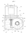
- FIG. 2 is an external view of the wiper motor of FIG. 1
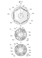
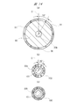
- FIG. 3 is a state where a gear cover is removed from the gear housing of FIG. 4 is a bottom view
- FIG. 4 is an explanatory view for explaining the detailed structure of the rotor and the rotating shaft
- FIG. 5A is a cross-sectional view taken along the line AA in FIG. 4
- FIG. 6C is a sectional view showing a modification of the rotating shaft magnet
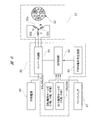
- FIG. 6 is a block diagram for explaining the electric system of the wiper motor.
- a vehicle 10 such as an automobile is provided with a windshield 11 as a windshield, and a wiper device 12 is mounted on the vehicle 10 so as to be close to the windshield 11.
- the wiper device 12 is activated by turning on a wiper switch (not shown) in the passenger compartment, thereby wiping off deposits adhering to the windshield 11.
- the wiper device 12 includes a wiper motor (brushless wiper motor) 20, a power transmission mechanism 14 that transmits the swinging motion of the wiper motor 20 to the pivot shafts 13a and 13b, and a base end side fixed to the pivot shafts 13a and 13b.
- the tip end side is provided with a pair of wiper members 15a and 15b which perform a reciprocating wiping operation on the windshield 11 by swinging movement of the pivot shafts 13a and 13b.
- the wiper members 15a and 15b are provided corresponding to the driver seat side and the passenger seat side, respectively.
- the wiper members 15a and 15b are wiper arms 16a and 16b and wiper blades 17a attached to the wiper arms 16a and 16b, respectively. , 17b.
- the swinging motion of the wiper motor 20 is transmitted to the pivot shafts 13a and 13b via the power transmission mechanism 14, so that the pivot shafts 13a and 13b swing. Become. In this way, the driving force of the wiper motor 20 is transmitted to the wiper members 15a and 15b, and the adhered matter adhering in the wiping ranges 11a and 11b of the windshield 11 is wiped by the wiper blades 17a and 17b.
- the wiper motor 20 includes a motor unit 30 and a speed reduction mechanism unit 40.
- the motor unit 30 includes a yoke 31 formed into a bottomed cylindrical shape by pressing a steel plate, and an annular stator 32 is fixed inside the yoke 31.
- U-phase, V-phase, and W-phase (three-phase) coils 32 a, 32 b, and 32 c are wound around the stator 32 in a star connection manner.
- a rotor 33 is rotatably provided inside the stator 32 through a predetermined gap (air gap).
- the rotor 33 is formed in a substantially cylindrical shape by laminating a plurality of steel plates.
- a plurality of plate-like permanent magnets 33a (six poles in the present embodiment) are embedded in the rotor 33 so as to extend in the axial direction, as shown in the shaded portion of FIG.
- the permanent magnets 33 a are provided at equal intervals (60 ° intervals) so that the polarities are alternately arranged along the circumferential direction of the rotor 33.
- the wiper motor 20 employs a brushless motor having an IPM (Interior / Permanent / Magnet) structure in which a plurality of permanent magnets 33 a are embedded in the rotor 33.
- IPM Interior / Permanent / Magnet
- the present invention is not limited to the brushless motor having the IPM structure, but can also be applied to a brushless motor having an SPM (SurfacemanPermanent Magnet) structure in which a plurality of permanent magnets are attached to the outer peripheral surface of the rotor.
- SPM SurfacemanPermanent Magnet
- Rotating shaft 33b penetrates and is fixed to the rotation center of rotor 33.
- the base end side (upper side in FIG. 3) of the rotating shaft 33b is rotatably supported by a bearing (not shown) provided at the bottom of the yoke 31, and the distal end side (lower side in FIG. 3) of the rotating shaft 33b is supported.
- the gear housing 41 that forms the speed reduction mechanism 40 is extended to the inside.
- the extending portion of the rotating shaft 33b into the gear housing 41, that is, the front end side and the substantially central portion located in the gear housing 41 of the rotating shaft 33b are formed by a pair of bearings (not shown) provided in the gear housing 41. Each is supported rotatably.
- a worm 51 forming a speed reduction mechanism 50 is integrally provided on the tip side of the rotary shaft 33b. Further, a rotary shaft magnet 34 formed in an annular shape is integrally provided at a portion near the worm 51 between the worm 51 and the rotor 33 of the rotary shaft 33b. The rotating shaft magnet 34 is provided at a portion where the rotating shaft 33b extends into the gear housing 41, and a plurality of permanent magnets 34a (the N poles and the S poles are alternately arranged along the circumferential direction of the rotating shaft 33b. (See the shaded portion in the figure). As shown in FIG.
- the number of poles of each permanent magnet 34a is 6 poles as in the case of each permanent magnet 33a inside the rotor 33, and equidistant from each other along the circumferential direction of the rotating shaft magnet 34 ( 60 intervals).
- the rotating shaft magnet 34 constitutes the first magnet and the second magnet in the present invention. That is, in the present embodiment, the first magnet and the second magnet are formed by a single rotating shaft magnet 34.
- the rotation shaft magnet 34 is used to detect the rotation speed of the rotation shaft 33b (function as the second magnet of the present invention), and the rotation position of the rotor 33 relative to the stator 32 is changed to the rotation shaft 33b. (Function as the first magnet of the present invention). Accordingly, as shown in FIGS. 5A and 5B, the rotational position of the rotating shaft 33b with respect to the stator 32 and the rotational position of the rotor 33 with respect to the stator 32 have the same positional relationship in the rotational direction.
- the polarities of the permanent magnets 33a (the rotor 33 side) and the polarities of the permanent magnets 34a (the rotating shaft magnet 34 side) are aligned in the axial direction of the rotating shaft 33b.
- the rotating shaft magnet 34 is fixed to the rotating shaft 33b so that the S-pole permanent magnets 33a and 34a are positioned at 30 ° with respect to the reference position C.
- each permanent magnet 34a of the rotating shaft magnet 34 must be set to the same number of poles (six poles) as the number of permanent magnets 33a of the rotor 33, as shown in FIG. 5B.
- each permanent magnet 34a can be set to 12 poles (twice as many as each permanent magnet 33a).
- the appearance timing of each permanent magnet 33a and each permanent magnet 34a accompanying the rotation of the rotor 33 may be synchronized, and therefore the number of poles of each permanent magnet 34a is an integral multiple of the number of poles of each permanent magnet 33a. (1 times, 2 times, 3 times, 4 times,...) May be set.
- each rotary shaft Hall IC 65a to 65c used to detect a change in the polarity of each permanent magnet 34a can be subdivided. Thereby, the detection accuracy of the rotational position of the rotor 33 with respect to the stator 32 is improved, and the rotor 33 can be controlled more finely.
- the speed reduction mechanism portion 40 includes an aluminum gear housing 41 and a plastic gear cover 42 that closes an opening 41 a (the front side in FIG. 3) of the gear housing 41. .
- the yoke 31 is fixed to the gear housing 41 via a fastening member (fixing screw or the like) (not shown), whereby the motor unit 30 and the speed reduction mechanism unit 40 are integrated to rotate with the worm 51 provided on the rotary shaft 33b.
- a shaft magnet 34 is arranged in the gear housing 41.
- a worm wheel 52 (not shown in detail) is rotatably provided inside the gear housing 41.
- the worm wheel 52 is formed in a disk shape from a resin material such as POM (polyacetal) plastic, for example, and gear teeth 52a (not shown in detail) are formed on the outer peripheral portion thereof.
- a worm 51 is meshed with the gear teeth 52 a of the worm wheel 52, and the worm wheel 52 constitutes a speed reduction mechanism 50 together with the worm 51.
- the base end side of the output shaft 52b is fixed to the rotation center of the worm wheel 52, and the output shaft 52b is rotatably supported by the boss portion 41b of the gear housing 41 via a bearing (not shown). .
- the distal end side of the output shaft 52b extends to the outside of the gear housing 41, and the power transmission mechanism 14 is fixed to the distal end portion of the output shaft 52b as shown in FIG.
- the rotational speed of the rotary shaft 33b is decelerated via the worm 51 and the worm wheel 52 (deceleration mechanism 50), and this decelerated and increased torque output is output to the power transmission mechanism 14 via the output shaft 52b. It is output.
- an annular output shaft magnet 53 (third magnet) is provided at the center of rotation of the worm wheel 52, and the output shaft magnet 53 extends around the base end side of the output shaft 52b. It is integrally fixed to the output shaft 52b via the worm wheel 52 so as to surround it. That is, the output shaft magnet 53 is integrally provided at a portion where the output shaft 52b extends into the gear housing 41. However, the output shaft magnet 53 can also be directly fixed to the output shaft 52 b penetrating the worm wheel 52.
- the output shaft magnet 53 is magnetized to the S pole in a range of about 270 ° along the circumferential direction, and the other range of about 90 ° is magnetized to the N pole.
- the output shaft magnet 53 constitutes a third magnet in the present invention, and the output shaft magnet 53 is used to detect the rotational position of the output shaft 52b relative to the gear housing 41.
- the opening 41a of the gear housing 41 is formed in the gear housing 41 to accommodate components such as the worm wheel 52, and the opening 41a is closed by a gear cover 42 as shown in FIG.
- a seal member (not shown) is provided between the gear housing 41 and the gear cover 42, thereby preventing rainwater or the like from entering the reduction mechanism 40 from between the gear housing 41 and the gear cover 42.
- a control board 60 is mounted inside the gear cover 42, and the vehicle 10 connected to a connector connecting portion (not shown) provided on the gear cover 42 is attached to the control board 60.
- An external power source 64 and a wiper switch 67 are electrically connected via a side external connector (not shown).
- the control board 60 is provided in the gear housing 41. As shown in FIG. 6, an inverter circuit 61, a control circuit 62, and a PWM signal generation circuit 63 are mounted on the control board 60.
- An external power source 64 such as an in-vehicle battery mounted on the vehicle 10 is electrically connected to the inverter circuit 61, and further, coils 32a, 32b, and 32c made of U phase, V phase, and W phase are electrically connected.
- the inverter circuit 61 includes a plurality of switching elements made of semiconductor elements such as FETs, and these switching elements are respectively connected to the positive electrode of the external power supply 64 and have three positive electrode sides corresponding to the U phase, V phase, and W phase.
- the control circuit 62 is electrically connected to the inverter circuit 61 and controls on / off of each switching element provided in the inverter circuit 61.
- the control circuit 62 is configured by a known microcomputer provided with a CPU, RAM, ROM and the like (not shown).
- the PWM signal generation circuit 63 determines a duty ratio for intermittently turning on / off each switching element of the inverter circuit 61, and sends the duty ratio signal to the control circuit 62. Thereby, the ratio at which each switching element of the inverter circuit 61 is individually turned on is adjusted, and the magnitude of the drive current supplied to each coil 32a, 32b, 32c is controlled.
- the control board 60 further includes three rotary shaft Hall ICs (U phase, V phase, W phase) 65a, 65b, 65c and two output shaft Hall ICs (A phase, B phase) 66a, 66b.
- Each of the Hall ICs 65a to 65c, 66a, 66b has the same configuration, and performs a switching operation according to a change in polarity (change from N pole to S pole or change from S pole to N pole) It is configured to generate a pulse signal (rectangular wave signal) (see FIG. 7). That is, each Hall IC 65a to 65c, 66a, 66b is a non-contact type sensor that is used as a set with a magnet.
- each of the rotary shaft hall ICs 65a to 65c is provided at a portion of the control board 60 facing the rotary shaft magnet 34. Specifically, each of the rotary shaft hall ICs 65a to 65c is provided on the control board 60 so as to face the outer peripheral surface (side surface) of the rotary shaft magnet 34 at equal intervals. As a result, the rotation shaft Hall ICs 65a to 65c sequentially generate pulse signals (electric signals) with a predetermined phase difference as the rotation shaft magnet 34 rotates (see FIG. 7).
- the rotary shaft Hall ICs 65a to 65c constitute the first sensor and the second sensor in the present invention. That is, in the present embodiment, the first sensor and the second sensor are formed by the common rotary shaft Hall ICs 65a to 65c. In order to detect the rotational position of the rotor 33 with respect to the stator 32, all of the U phase, V phase, and W phase that are the outputs of the rotary shaft hall ICs 65a to 65c are used (as the first sensor of the present invention). function).
- Each output shaft Hall IC 66a, 66b is provided at a portion of the control board 60 facing the output shaft magnet 53, as shown in FIG. Specifically, each of the output shaft hall ICs 66a and 66b faces the upper surface (annular surface) of the output shaft magnet 53 and has a predetermined interval (approximately 90 ° interval) along the circumferential direction of the output shaft magnet 53. Is provided on the control board 60. As a result, each output shaft Hall IC 66a, 66b sequentially generates a pulse signal (electric signal) with a predetermined phase difference as the output shaft magnet 53 rotates (see FIG. 7).
- each output shaft Hall IC 66a, 66b constitutes a third sensor in the present invention.
- a wiper switch 67 provided in the vehicle interior of the vehicle 10 is electrically connected to the control circuit 62, and an operation signal of the wiper switch 67 is input to the control circuit 62. It has become.
- the operation signal of the wiper switch 67 differs depending on the operation state of the wiper switch 67 by the operator. For example, the high-speed wiping operation signal (High), the low-speed wiping operation signal (Low), the intermittent wiping operation signal (Int), etc. Is mentioned.
- FIG. 7 is a pulse waveform diagram showing the output state of electrical signals from each Hall IC.
- U-phase pulse indicates the output waveform of the rotary shaft Hall IC 65a
- V-phase pulse indicates the output waveform of the rotary shaft Hall IC 65b
- W-phase pulse indicates the output waveform of the rotary shaft Hall IC 65c.
- the “A phase pulse” represents the output waveform of the output shaft Hall IC 66a
- the “B phase pulse” represents the output waveform of the output shaft Hall IC 66b.
- the symbol “H” in FIG. 7 represents a state in which the Hall IC is switched on
- the symbol “L” represents a state in which the Hall IC is switched off.
- the wiper switch 67 When the wiper switch 67 is operated by the operator to rotate the wiper motor 20 (0 sec), the coils 32a, 32b, and 32c wound around the stator 32 are supplied from the external power source 64 via the inverter circuit 61. The drive current is sequentially supplied. As a result, the rotor 33 rotates at a predetermined rotational speed, and each wiper blade 17a, 17b starts a wiping operation from the lower reverse position (stop position) on the windshield 11 toward the upper reverse position (see FIG. 1). ).
- the rotational speed of the rotor 33 that is, the wiping speed of each wiper blade 17a, 17b is determined by an operation signal (High, Low, or Int) from the wiper switch 67.
- a pulse signal with a predetermined phase difference and a relatively short interval is transmitted from each of the rotary shaft Hall ICs 65a to 65c as the rotor 33 rotates. Are output sequentially (from 0 sec).
- the appearance timing and the number of occurrences of the pulse signals composed of the U phase, the V phase, and the W phase are input to the control circuit 62 and stored.
- the control circuit 62 detects the rotational position of the rotor 33 with respect to the stator 32 based on each pulse signal (three), controls on / off of each switching element provided in the inverter circuit 61, and rotates the wiper motor 20. To drive. Further, the control circuit 62 detects the rotational speed of the rotary shaft 33b based on two of the pulse signals, and thereby rotates the wiper motor 20 so that the rotational speed matches the operation signal from the wiper switch 67. To drive.
- the output shaft hall ICs 66a and 66b have a predetermined phase difference and comparison with the rotation of the worm wheel 52 (output shaft 52b). Pulse signals with long intervals are output sequentially (from 0 sec). The appearance timing and the number of occurrences of the pulse signals composed of the A phase and the B phase are input to the control circuit 62 and stored. Based on each pulse signal, the control circuit 62 detects the rotational position of the output shaft 52b relative to the gear housing 41, thereby detecting the position of each wiper blade 17a, 17b relative to the windshield 11. Then, the control circuit 62 controls the on / off of each switching element provided in the inverter circuit 61 to rotationally drive the wiper motor 20, thereby stopping each wiper blade 17a, 17b at a predetermined position on the windshield 11. Or reverse operation.
- each pulse signal is a mirror image object on the left and right sides in the figure, with this portion (1.0 sec portion) as a boundary.
- the rotating shaft magnet 34 (first magnet, second magnet) is provided in the extending portion of the rotating shaft 33b into the gear housing 41.
- the rotary shaft Hall ICs 65a to 65c (first sensor and second sensor) are provided on the control board 60 in the gear housing 41 so as to face the rotary shaft magnet.
- the rotational position of the rotary shaft 33b with respect to the stator 32 that is, the rotational position of the rotor 33 with respect to the stator 32 is detected by each of the rotary shaft hall ICs 65a to 65c, and further, the rotational shaft 33b is rotated by each of the rotary shaft hall ICs 65a to 65c. The number was detected.
- the rotary shaft hall ICs 65a to 65c (shared) for detecting the rotational position of the rotor 33 and the rotational speed of the rotary shaft 33b, and the output shaft hall ICs 66a for detecting the rotational position of the output shaft 52b relative to the gear housing 41 are provided.
- 66b can be integrated on the control board 60. Therefore, since it is not necessary to provide a sensor (first sensor referred to in the present invention) for detecting the rotational position of the rotor 33 near the rotor 33 of the wiper motor 20, the dimension along the axial direction of the rotary shaft 33b of the wiper motor 20 is shortened. Further downsizing can be realized.
- a magnet and a sensor for detecting the rotational position of the rotor 33, and a magnet for detecting the rotational speed of the rotary shaft 33b.
- the sensors are formed in common with the rotary shaft Hall ICs 65a to 65c and the rotary shaft magnet 34, the number of magnets and the number of sensors can be reduced.
- the wiper motor 20 can be reduced in cost and weight.
- each permanent magnet 33a of the rotor 33 and each permanent magnet 34a of the rotating shaft magnet 34 are alternately arranged in the circumferential direction of the rotating shaft 33b. Since the polarities of the permanent magnets 33a and the polarities of the permanent magnets 34a are aligned in the axial direction of the rotating shaft 33b, the rotational position of the rotor 33 relative to the stator 32 is detected, and the rotor based on this 33 control can be simplified.
- FIG. 8 is a bottom view corresponding to FIG. 3 of the wiper motor according to the second embodiment
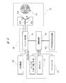
- FIG. 9 is a block diagram for explaining the electric system of the wiper motor of FIG. 8
- FIG. 10 is an electric diagram from each Hall IC and MR sensor. The pulse waveform diagram which shows the output state of a signal is each represented.
- the wiper motor 70 according to the second embodiment is different from the wiper motor 20 according to the first embodiment in the shape of the third magnet and the type of the third sensor.
- a tablet-like output shaft magnet 71 (third magnet) is provided through a worm wheel 52 at a portion of the output shaft 52b that extends into the gear housing 41.
- the magnet 71 rotates integrally with the output shaft 52b.
- the output shaft magnet 71 is magnetized to the S pole in a range of approximately 180 ° along the circumferential direction, and the other range of approximately 180 ° is magnetized to the N pole.
- An MR sensor (third sensor) 72 made of a magnetoresistive element is provided at a portion of the control board 60 facing the output shaft magnet 71.
- the MR sensor 72 is electrically connected to the control circuit 62 as shown in FIG. 9, and an output voltage that is an electrical signal from the MR sensor 72 is input to the control circuit 62.
- the resistance value of the MR sensor 72 changes due to the change in the direction of the magnetic flux accompanying the rotation of the output shaft magnet 71 facing the MR sensor 72. As a result, the output voltage (0 to 500 mV) is substantially reduced as shown in FIG. It is designed to change linearly.
- the MR sensor 72 is set so that the output voltage becomes the maximum value at the time point of 1.0 sec that is the inversion position of each wiper blade 17a, 17b. Thereby, the rotational position (absolute position) of the output shaft 52b relative to the gear housing 41 can be detected.
- the wiper motor 70 according to the second embodiment formed as described above the same operational effects as those of the first embodiment described above can be obtained.
- the output shaft magnet 71 is shaped like a tablet, so that it is smaller and lighter than the output shaft magnet 53 of the first embodiment.
- the third sensor can be configured by one MR sensor 72, the mounting of electronic components including the MR sensor 72 on the control board 60 can be simplified. Furthermore, since the MR sensor 72 detects the absolute position of the output shaft 52b with respect to the gear housing 41, the control circuit 62 can omit calculation processing for position detection.
- FIG. 11 is a bottom view corresponding to FIG. 3 of the wiper motor according to the third embodiment
- FIG. 12 is a block diagram illustrating an electric system of the wiper motor of FIG.
- the wiper motor 80 according to the third embodiment is formed of a single magnet by sharing the first magnet, the second magnet, and the third magnet in the present invention as compared with the wiper motor 20 according to the first embodiment.
- the first sensor, the second sensor, and the third sensor in the present invention are shared and formed by one sensor.
- a tablet-like output shaft magnet 81 (first magnet, second magnet, third magnet) is provided via a worm wheel 52 at a portion where the output shaft 52 b extends into the gear housing 41.
- the output shaft magnet 81 rotates integrally with the output shaft 52b.
- the output shaft magnet 81 is magnetized to the S pole in a range of approximately 180 ° along the circumferential direction, and the other range of approximately 180 ° is magnetized to the N pole.
- the pulse signals (three types) corresponding to the U phase, V phase, and W phase obtained in a pseudo manner as the output shaft 52b rotates, and the above-mentioned
- a magnetic rotary encoder 82 (first sensor, second sensor, third sensor) capable of outputting the same electrical signal as that of the MR sensor 72 (see FIG. 8) according to the second embodiment is provided.
- the rotary encoder 82 is electrically connected to the control circuit 62 as shown in FIG. 12, and a pulse signal and an output voltage, which are electrical signals from the rotary encoder 82, are input to the control circuit 62. Yes.
- the electrical signal from the rotary encoder 82 is the same as that shown in FIG.
- the rotation state (the number of rotations and the rotation position) of the rotation shaft 33b is not directly detected as in the first embodiment and the second embodiment.
- the rotation state of the rotary shaft 33b is estimated by the control circuit 62 from pulse signals (three types) corresponding to the U phase, V phase, and W phase obtained in a pseudo manner by the rotation of the worm wheel 52.
- the wiper motor 80 according to the third embodiment formed as described above the same operational effects as those of the first embodiment described above can be achieved.
- the third embodiment includes only one output shaft magnet 81 and one rotary encoder 82, the wiper motor 80 can be further reduced in size and weight. Further, the control logic of the wiper motor 80 can be further simplified.
- FIG. 13 is a view corresponding to FIG. 4 of the wiper motor according to the fourth embodiment
- FIG. 14A is a sectional view taken along the line DD in FIG. 13
- FIG. 13B is a view taken along the line EE in FIG.
- a sectional view along (c) shows a sectional view showing a modification of the rotating shaft magnet.
- the structures of the rotor 90 and the rotating shaft magnet 100 are different from those in the first embodiment described above. Moreover, the point which fixed the radial bearing 110 between the rotor 90 of the rotating shaft 33b and the magnet 100 for rotating shafts also differs.
- the rotor 90 is formed in a substantially cylindrical shape by cutting a round bar or the like, and is press-fitted and fixed so as to be able to rotate integrally with the rotary shaft 33b.
- a cylindrical permanent magnet (ring magnet) 91 is attached to the outer peripheral surface of the rotor 90. That is, the rotor 90 according to the fourth embodiment employs an SPM (Surface Permanent Magnet) structure.
- SPM Surface Permanent Magnet
- the permanent magnet 91 is used as a ring magnet so as to cover the entire circumference of the rotor 90, a larger number of poles can be provided as compared with the first embodiment. Therefore, in the fourth embodiment, it is possible to improve the degree of design freedom, that is, to cope with diversification of motor specifications.
- the rotor 90 formed into a substantially cylindrical shape by cutting a round bar or the like is shown.
- the rotor is laminated by laminating a plurality of steel plates. You may make it form in a substantially cylindrical shape.
- the permanent magnet 91 is formed by alternately magnetizing a plurality of magnetic poles along the circumferential direction (six poles in the present embodiment), and the rotor 90 and the permanent magnet 91 are made of, for example, an adhesive (not shown). Z)). Further, as shown in FIG. 13, the permanent magnet 91 is provided with a skew SK inclined toward the axial direction of the rotor 90, thereby suppressing the occurrence of problems such as cogging torque and torque ripple. Yes.
- a so-called segment type (divided type) permanent magnet divided into a plurality of pieces in the circumferential direction can also be used. In this case, in order to prevent dropping (peeling) from the rotor 90, it is desirable to cover each permanent magnet with a cylindrical cover as shown in FIGS. 5 (b) and 5 (c).
- the rotating shaft magnet 100 is formed of a cylindrical permanent magnet (ring magnet) in the same manner as the permanent magnet 91 fixed to the rotor 90.
- the rotating shaft magnet 100 is formed by alternately magnetizing a plurality of magnetic poles along the circumferential direction, and has six poles like the permanent magnet 91.
- the rotary shaft magnet 100 is not provided with a skew SK like the permanent magnet 91.
- the rotating shaft magnet 100 is a ring magnet, a large number of poles can be provided in the same manner as the permanent magnet 91, and thus finer control is possible.
- an attachment cylinder 101 for attaching the rotating shaft magnet 100 to the rotating shaft 33b is provided.
- the mounting cylinder 101 is formed of, for example, a brass tube material (not shown in detail), and a fixed recess (around the rotation shaft 33b with the rotation shaft magnet 100 attached). (Not shown) is fixed by caulking.
- the rotating shaft magnet 100 constitutes the first magnet and the second magnet in the present invention.
- a so-called segment type (divided type) permanent magnet divided into a plurality of circumferential directions can be used.
- the number of poles of the rotary shaft magnet 100 can be set to 12 poles (twice as many as the permanent magnet 91) as shown in FIG.
- a ball bearing (ball bearing) made of an inner race, an outer race, and a plurality of steel balls is employed.
- the radial bearing 110 is fixed between the rotor 90 and the rotary shaft magnet 100 by press-fitting and fixing the inner race of the radial bearing 110 to the rotary shaft 33b.
- the outer race of the radial bearing 110 is fixed to a predetermined portion of the gear housing 41 (see FIGS. 2 and 3) by a stopper member (not shown).
- the radial bearing 110 supports the rotary shaft 33b in a rotatable manner and restricts movement of the rotary shaft 33b in the axial direction. Therefore, it is not necessary to provide thrust bearings or the like on both sides in the axial direction of the rotating shaft 33b, and thus the number of parts can be reduced, and the sliding loss of the rotating shaft 33b can be greatly reduced.
- the present invention is not limited to the above-described embodiments, and it goes without saying that various modifications can be made without departing from the scope of the invention.
- the first magnet, the second magnet, and the third magnet in the present invention may be separated from each other as in the above embodiments.
- the first sensor, the second sensor, and the third sensor in the present invention may be separated from each other without being shared as in the above embodiments.
- the wiper device 12 is not limited to the windshield 11 and may wipe the rear glass (not shown).
- the wiper arms 16a and 16b are connected to the output shaft 52b via the power transmission mechanism 14 as shown in FIG. 1, but the wiper arm may be directly connected to the output shaft. good.
- the present invention can be applied not only to the inner rotor type brushless motor in which the rotors 33 and 90 are rotatably arranged inside the stator 32 but also to an outer rotor type brushless motor in which the rotor is arranged outside the stator.
- the rotary shaft 33b to which the rotor 90 according to the fourth embodiment is fixed is provided with the radial bearing 110.
- the rotary shaft 33b to which the rotor 33 according to the first embodiment is fixed is shown.
- a radial bearing 110 may be provided (see FIG. 4).
- the brushless wiper motor is used to drive a wiper member forming a wiper device provided in a vehicle such as an automobile and wipe the windshield.
Abstract
Description
Claims (5)
- ウィンドシールドに付着した付着物を払拭するワイパ部材を揺動駆動するブラシレスワイパモータであって、
コイルが巻装されたステータと、
永久磁石および回転軸を備えたロータと、
前記回転軸の回転を外部に出力する出力軸と、
前記出力軸を回転自在に支持するギヤハウジングと、
前記ギヤハウジング内に設けられる制御基板と、
前記回転軸の前記ギヤハウジング内への延出部分に一体に設けられ、前記回転軸の前記ステータに対する回転位置を検出するために用いられる第1磁石と、
前記第1磁石と対向するよう前記制御基板に設けられ、前記第1磁石の相対回転に伴い電気信号を発生する第1センサと、
前記回転軸の前記ギヤハウジング内への延出部分に一体に設けられ、前記回転軸の回転数を検出するために用いられる第2磁石と、
前記第2磁石と対向するよう前記制御基板に設けられ、前記第2磁石の相対回転に伴い電気信号を発生する第2センサと、
前記出力軸の前記ギヤハウジング内への延出部分に一体に設けられ、前記出力軸の前記ギヤハウジングに対する回転位置を検出するために用いられる第3磁石と、
前記第3磁石と対向するよう前記制御基板に設けられ、前記第3磁石の相対回転に伴い電気信号を発生する第3センサと、
を有することを特徴とするブラシレスワイパモータ。 A brushless wiper motor that swings and drives a wiper member for wiping off deposits attached to the windshield,
A stator wound with a coil;
A rotor with a permanent magnet and a rotating shaft;
An output shaft for outputting the rotation of the rotation shaft to the outside;
A gear housing that rotatably supports the output shaft;
A control board provided in the gear housing;
A first magnet provided integrally with a portion of the rotating shaft extending into the gear housing and used for detecting a rotational position of the rotating shaft with respect to the stator;
A first sensor provided on the control board so as to face the first magnet and generating an electrical signal in accordance with relative rotation of the first magnet;
A second magnet provided integrally with the extending portion of the rotating shaft into the gear housing and used for detecting the rotational speed of the rotating shaft;
A second sensor provided on the control board so as to face the second magnet and generating an electrical signal in accordance with relative rotation of the second magnet;
A third magnet provided integrally with an extension portion of the output shaft into the gear housing and used for detecting a rotational position of the output shaft with respect to the gear housing;
A third sensor provided on the control board so as to face the third magnet and generating an electrical signal in accordance with the relative rotation of the third magnet;
A brushless wiper motor comprising: - 請求項1記載のブラシレスワイパモータにおいて、前記第1磁石と前記第2磁石とを共通の磁石で形成し、前記第1センサと前記第2センサとを共通のセンサで形成したことを特徴とするブラシレスワイパモータ。 2. The brushless wiper motor according to claim 1, wherein the first magnet and the second magnet are formed of a common magnet, and the first sensor and the second sensor are formed of a common sensor. Wiper motor.
- 請求項1記載のブラシレスワイパモータにおいて、前記永久磁石および前記第1,第2磁石は、それぞれ前記回転軸の周方向に向けて交互に極性が並ぶよう着磁され、前記永久磁石の極性と前記第1,第2磁石の極性とを、前記回転軸の軸方向に向けて整合させたことを特徴とするブラシレスワイパモータ。 2. The brushless wiper motor according to claim 1, wherein the permanent magnet and the first and second magnets are magnetized so that polarities are alternately arranged in a circumferential direction of the rotating shaft, and the polarity of the permanent magnet and the first magnet A brushless wiper motor, wherein the polarities of the first and second magnets are aligned in the axial direction of the rotating shaft.
- 請求項3記載のブラシレスワイパモータにおいて、前記第1,第2磁石の極数を、前記永久磁石の極数の整数倍に設定したことを特徴とするブラシレスワイパモータ。 4. The brushless wiper motor according to claim 3, wherein the number of poles of the first and second magnets is set to an integral multiple of the number of poles of the permanent magnet.
- ウィンドシールドに付着した付着物を払拭するワイパ部材を揺動駆動するブラシレスワイパモータであって、
コイルが巻装されたステータと、
永久磁石および回転軸を備えたロータと、
前記回転軸の回転を外部に出力する出力軸と、
前記出力軸を回転自在に支持するギヤハウジングと、
前記ギヤハウジング内に設けられる制御基板と、
前記出力軸の前記ギヤハウジング内への延出部分に一体に設けられ、前記回転軸の前記ステータに対する回転位置を検出するために用いられる第1磁石と、
前記第1磁石と対向するよう前記制御基板に設けられ、前記第1磁石の相対回転に伴い電気信号を発生する第1センサと、
前記出力軸の前記ギヤハウジング内への延出部分に一体に設けられ、前記回転軸の回転数を検出するために用いられる第2磁石と、
前記第2磁石と対向するよう前記制御基板に設けられ、前記第2磁石の相対回転に伴い電気信号を発生する第2センサと、
前記出力軸の前記ギヤハウジング内への延出部分に一体に設けられ、前記出力軸の前記ギヤハウジングに対する回転位置を検出するために用いられる第3磁石と、
前記第3磁石と対向するよう前記制御基板に設けられ、前記第3磁石の相対回転に伴い電気信号を発生する第3センサと、
を有することを特徴とするブラシレスワイパモータ。 A brushless wiper motor that swings and drives a wiper member for wiping off deposits attached to the windshield,
A stator wound with a coil;
A rotor with a permanent magnet and a rotating shaft;
An output shaft for outputting the rotation of the rotation shaft to the outside;
A gear housing that rotatably supports the output shaft;
A control board provided in the gear housing;
A first magnet provided integrally with an extension portion of the output shaft into the gear housing and used for detecting a rotational position of the rotary shaft relative to the stator;
A first sensor provided on the control board so as to face the first magnet and generating an electrical signal in accordance with relative rotation of the first magnet;
A second magnet provided integrally with an extension portion of the output shaft into the gear housing and used for detecting the rotational speed of the rotary shaft;
A second sensor provided on the control board so as to face the second magnet and generating an electrical signal in accordance with relative rotation of the second magnet;
A third magnet provided integrally with an extension portion of the output shaft into the gear housing and used for detecting a rotational position of the output shaft with respect to the gear housing;
A third sensor provided on the control board so as to face the third magnet and generating an electrical signal in accordance with the relative rotation of the third magnet;
A brushless wiper motor comprising:
Priority Applications (4)
| Application Number | Priority Date | Filing Date | Title |
|---|---|---|---|
| CN201380079714.XA CN105556812A (en) | 2013-09-24 | 2013-09-24 | Brushless wiper motor |
| EP13894252.9A EP3051672A4 (en) | 2013-09-24 | 2013-09-24 | Brushless wiper motor |
| PCT/JP2013/075712 WO2015045003A1 (en) | 2013-09-24 | 2013-09-24 | Brushless wiper motor |
| US15/024,156 US20160241108A1 (en) | 2013-09-24 | 2013-09-24 | Brushless wiper motor |
Applications Claiming Priority (1)
| Application Number | Priority Date | Filing Date | Title |
|---|---|---|---|
| PCT/JP2013/075712 WO2015045003A1 (en) | 2013-09-24 | 2013-09-24 | Brushless wiper motor |
Publications (1)
| Publication Number | Publication Date |
|---|---|
| WO2015045003A1 true WO2015045003A1 (en) | 2015-04-02 |
Family
ID=52742217
Family Applications (1)
| Application Number | Title | Priority Date | Filing Date |
|---|---|---|---|
| PCT/JP2013/075712 WO2015045003A1 (en) | 2013-09-24 | 2013-09-24 | Brushless wiper motor |
Country Status (4)
| Country | Link |
|---|---|
| US (1) | US20160241108A1 (en) |
| EP (1) | EP3051672A4 (en) |
| CN (1) | CN105556812A (en) |
| WO (1) | WO2015045003A1 (en) |
Families Citing this family (19)
| Publication number | Priority date | Publication date | Assignee | Title |
|---|---|---|---|---|
| DE102016221052A1 (en) * | 2016-10-26 | 2018-04-26 | Robert Bosch Gmbh | Wiper drive for a wiper system of a motor vehicle |
| FR3059174B1 (en) | 2016-11-21 | 2019-01-25 | Valeo Systemes D'essuyage | MOTOR-REDUCER, WIPING SYSTEM AND CONTROL METHOD THEREOF |
| DE102017100741B4 (en) * | 2017-01-16 | 2021-02-11 | SMR Patents S.à.r.l. | Wiper device and method for wiping an optical element and rearview device or driver assistance device for use in a vehicle |
| JP6430570B2 (en) * | 2017-03-27 | 2018-11-28 | 岡山県 | In-wheel motor |
| DE102017207929A1 (en) * | 2017-05-10 | 2018-11-15 | Mahle Lnternational Gmbh | Adjusting device and associated production method |
| FR3066970B1 (en) * | 2017-06-02 | 2021-01-01 | Valeo Systemes Dessuyage | MOTOR-REDUCER FOR MOTOR VEHICLE WIPING SYSTEM |
| DE102017121222A1 (en) * | 2017-09-13 | 2019-03-14 | Valeo Systèmes d'Essuyage | wiper motor |
| EP3474417A1 (en) | 2017-10-20 | 2019-04-24 | Siemens Aktiengesellschaft | Modified rotor of a reluctance machine for torque increase |
| EP3503379B1 (en) * | 2017-11-02 | 2021-10-06 | Igarashi Electric Works Ltd. | Control device of direct current motor |
| JP7080702B2 (en) * | 2018-04-12 | 2022-06-06 | 株式会社ミツバ | Motors and brushless wiper motors |
| JP7080703B2 (en) | 2018-04-12 | 2022-06-06 | 株式会社ミツバ | Motors and brushless wiper motors |
| FR3083191B1 (en) * | 2018-06-29 | 2020-06-19 | Valeo Systemes D'essuyage | MOTOR REDUCER, WIPING SYSTEM AND CONTROL METHOD THEREOF |
| DE102018210816A1 (en) * | 2018-06-30 | 2020-01-02 | Robert Bosch Gmbh | Sensor device for an electrical machine, method for operating a sensor device |
| DE102018211438A1 (en) * | 2018-07-10 | 2020-01-16 | Robert Bosch Gmbh | Sensor for an engine |
| CN111255721A (en) * | 2018-12-03 | 2020-06-09 | 蒋亮健 | Swinging angle adjusting and sampling device for electric fan |
| JP7250534B2 (en) * | 2019-01-25 | 2023-04-03 | 日本電産サンキョー株式会社 | Encoders and motors with encoders |
| DE102019113549A1 (en) * | 2019-05-21 | 2020-11-26 | Valeo Systèmes d'Essuyage | Method for detecting the angular positions of rotating parts of a windshield wiper motor and a windshield wiper motor |
| CN110108198B (en) * | 2019-05-31 | 2024-03-08 | 湖南联诚轨道装备有限公司 | Pneumatic wiper motor position detection device |
| DE102020131667A1 (en) * | 2020-11-30 | 2022-06-02 | Minebea Mitsumi Inc. | Arrangement with a component rotatable about an axis of rotation for an actuator and a sensor element fastened to the rotatable component |
Citations (5)
| Publication number | Priority date | Publication date | Assignee | Title |
|---|---|---|---|---|
| JPH06105521A (en) | 1992-09-17 | 1994-04-15 | Hitachi Ltd | Inner rotor type brushless motor |
| JP2003274624A (en) * | 2002-03-15 | 2003-09-26 | Hitachi Metals Ltd | Magnet unit for detecting angle of rotation |
| JP2008174177A (en) * | 2007-01-22 | 2008-07-31 | Mitsuba Corp | Wiper device |
| JP2009225520A (en) | 2008-03-14 | 2009-10-01 | Mitsuba Corp | Electric motor and manufacturing method therefor |
| JP2013223317A (en) * | 2012-04-16 | 2013-10-28 | Mitsuba Corp | Brushless windshield wiper motor |
Family Cites Families (13)
| Publication number | Priority date | Publication date | Assignee | Title |
|---|---|---|---|---|
| US5860185A (en) * | 1996-08-23 | 1999-01-19 | Itt Automotive Electrical Systems, Inc. | Reversing wiper motor system |
| US5821710A (en) * | 1996-09-30 | 1998-10-13 | Hitachi Metals, Ltd. | Brushless motor having permanent magnets |
| DE19858630A1 (en) * | 1998-12-18 | 2000-06-21 | Bosch Gmbh Robert | Drive for adjustable vehicle part especially sliding roof, has circuit board at radial distance from driven element path greater than size of sensor, and magnetic flux guiding body between sensor and switching body |
| JP3879413B2 (en) * | 2001-02-28 | 2007-02-14 | 株式会社日立製作所 | Conveying system and rotating electric machine |
| JP3937966B2 (en) * | 2002-07-31 | 2007-06-27 | 株式会社日立製作所 | Rotating electric machine and automobile equipped with it |
| JP4129875B2 (en) * | 2005-03-08 | 2008-08-06 | 東京パーツ工業株式会社 | Electric motor with reduction mechanism |
| KR20070110806A (en) * | 2006-05-15 | 2007-11-20 | 소니온 호르젠스 에이/에스 | Miniature electro-dynamic motor |
| DE102009014595A1 (en) * | 2009-03-24 | 2010-09-30 | Magna Powertrain Ag & Co Kg | gear unit |
| CN102118078A (en) * | 2009-12-30 | 2011-07-06 | 德昌电机(深圳)有限公司 | Motor driving assembly |
| DE102010041744A1 (en) * | 2010-09-30 | 2012-04-05 | Zf Lenksysteme Gmbh | Steering gear with electric motor, control unit and sensor as well as electric power steering system equipped therewith |
| KR101758916B1 (en) * | 2010-12-21 | 2017-07-17 | 엘지이노텍 주식회사 | EPS Motor having steering angle sensor |
| JP5700217B2 (en) * | 2011-07-28 | 2015-04-15 | 日本電産株式会社 | motor |
| DE102012100829A1 (en) * | 2012-02-01 | 2013-08-01 | Valeo Systèmes d'Essuyage | Device for detecting the angular position of a shaft of an electric motor and windscreen wiper motor with a device for detecting the angular position |
-
2013
- 2013-09-24 US US15/024,156 patent/US20160241108A1/en not_active Abandoned
- 2013-09-24 EP EP13894252.9A patent/EP3051672A4/en not_active Withdrawn
- 2013-09-24 CN CN201380079714.XA patent/CN105556812A/en active Pending
- 2013-09-24 WO PCT/JP2013/075712 patent/WO2015045003A1/en active Application Filing
Patent Citations (5)
| Publication number | Priority date | Publication date | Assignee | Title |
|---|---|---|---|---|
| JPH06105521A (en) | 1992-09-17 | 1994-04-15 | Hitachi Ltd | Inner rotor type brushless motor |
| JP2003274624A (en) * | 2002-03-15 | 2003-09-26 | Hitachi Metals Ltd | Magnet unit for detecting angle of rotation |
| JP2008174177A (en) * | 2007-01-22 | 2008-07-31 | Mitsuba Corp | Wiper device |
| JP2009225520A (en) | 2008-03-14 | 2009-10-01 | Mitsuba Corp | Electric motor and manufacturing method therefor |
| JP2013223317A (en) * | 2012-04-16 | 2013-10-28 | Mitsuba Corp | Brushless windshield wiper motor |
Non-Patent Citations (1)
| Title |
|---|
| See also references of EP3051672A4 |
Also Published As
| Publication number | Publication date |
|---|---|
| CN105556812A (en) | 2016-05-04 |
| EP3051672A1 (en) | 2016-08-03 |
| US20160241108A1 (en) | 2016-08-18 |
| EP3051672A4 (en) | 2017-06-28 |
Similar Documents
| Publication | Publication Date | Title |
|---|---|---|
| WO2015045003A1 (en) | Brushless wiper motor | |
| US8659251B2 (en) | Wiper motor | |
| JP6545169B2 (en) | Brushless wiper motor and method of assembling the same | |
| US9929624B2 (en) | Brushless motor and wiper apparatus | |
| WO2016010021A1 (en) | Brushless wiper motor | |
| JP6634372B2 (en) | Brushless wiper motor | |
| JP6324946B2 (en) | Brushless wiper motor | |
| JP4981420B2 (en) | Electric motor with reduction mechanism | |
| JP2013223317A (en) | Brushless windshield wiper motor | |
| JP2014195389A (en) | Brushless motor and wiper device | |
| JP2013198188A (en) | Brushless motor and wiper device | |
| JP6640586B2 (en) | Brushless motor | |
| JP4298991B2 (en) | Wiper device control method, wiper device, and motor with speed reduction mechanism | |
| JP6410393B2 (en) | Wiper motor | |
| WO2011107407A3 (en) | Geared electric motor for vehicle applications | |
| JP6552422B2 (en) | Brushless motor | |
| JP2004254455A (en) | Electric motor equipped with reduction mechanism | |
| JP6091086B2 (en) | Motor equipment | |
| JP6286293B2 (en) | Wiper device | |
| JP7210478B2 (en) | Gear motor for automotive wiping system | |
| CN116505804A (en) | Method for correcting advance angle, advance angle setting device, motor device, and in-vehicle device | |
| JP2021048661A (en) | Brushless motor | |
| JP2005229688A (en) | Dc brushless motor |
Legal Events
| Date | Code | Title | Description |
|---|---|---|---|
| WWE | Wipo information: entry into national phase |
Ref document number: 201380079714.X Country of ref document: CN |
|
| 121 | Ep: the epo has been informed by wipo that ep was designated in this application |
Ref document number: 13894252 Country of ref document: EP Kind code of ref document: A1 |
|
| WWE | Wipo information: entry into national phase |
Ref document number: 15024156 Country of ref document: US |
|
| NENP | Non-entry into the national phase |
Ref country code: DE |
|
| REEP | Request for entry into the european phase |
Ref document number: 2013894252 Country of ref document: EP |
|
| WWE | Wipo information: entry into national phase |
Ref document number: 2013894252 Country of ref document: EP |
|
| NENP | Non-entry into the national phase |
Ref country code: JP |