EP3170584A1 - Schaltpositions-erkennungssystem, gussvorrichtung, schaltpositions-erkennungsverfahren sowie verfahren zur herstellung eines gussproduktes - Google Patents
Schaltpositions-erkennungssystem, gussvorrichtung, schaltpositions-erkennungsverfahren sowie verfahren zur herstellung eines gussproduktes Download PDFInfo
- Publication number
- EP3170584A1 EP3170584A1 EP15821561.6A EP15821561A EP3170584A1 EP 3170584 A1 EP3170584 A1 EP 3170584A1 EP 15821561 A EP15821561 A EP 15821561A EP 3170584 A1 EP3170584 A1 EP 3170584A1
- Authority
- EP
- European Patent Office
- Prior art keywords
- pouring cup
- marker
- position detection
- mold
- pouring
- Prior art date
- Legal status (The legal status is an assumption and is not a legal conclusion. Google has not performed a legal analysis and makes no representation as to the accuracy of the status listed.)
- Granted
Links
- 238000001514 detection method Methods 0.000 title claims abstract description 80
- 238000005266 casting Methods 0.000 title claims description 58
- 238000000034 method Methods 0.000 title claims description 32
- 238000004519 manufacturing process Methods 0.000 title description 4
- 239000003550 marker Substances 0.000 claims abstract description 117
- 238000012545 processing Methods 0.000 claims abstract description 34
- 239000013618 particulate matter Substances 0.000 claims description 60
- 239000000155 melt Substances 0.000 claims description 22
- 239000003779 heat-resistant material Substances 0.000 claims description 7
- 238000010276 construction Methods 0.000 description 15
- 238000010586 diagram Methods 0.000 description 11
- 239000000047 product Substances 0.000 description 10
- 238000007664 blowing Methods 0.000 description 6
- 239000002184 metal Substances 0.000 description 6
- 229910052751 metal Inorganic materials 0.000 description 6
- 239000004576 sand Substances 0.000 description 5
- XEEYBQQBJWHFJM-UHFFFAOYSA-N Iron Chemical compound [Fe] XEEYBQQBJWHFJM-UHFFFAOYSA-N 0.000 description 4
- 239000000428 dust Substances 0.000 description 4
- 238000004891 communication Methods 0.000 description 3
- 238000000605 extraction Methods 0.000 description 3
- 238000012937 correction Methods 0.000 description 2
- 230000005484 gravity Effects 0.000 description 2
- 229910052742 iron Inorganic materials 0.000 description 2
- 238000007711 solidification Methods 0.000 description 2
- 230000008023 solidification Effects 0.000 description 2
- NCGICGYLBXGBGN-UHFFFAOYSA-N 3-morpholin-4-yl-1-oxa-3-azonia-2-azanidacyclopent-3-en-5-imine;hydrochloride Chemical compound Cl.[N-]1OC(=N)C=[N+]1N1CCOCC1 NCGICGYLBXGBGN-UHFFFAOYSA-N 0.000 description 1
- 229910000831 Steel Inorganic materials 0.000 description 1
- 239000000919 ceramic Substances 0.000 description 1
- 238000011161 development Methods 0.000 description 1
- 230000000694 effects Effects 0.000 description 1
- 239000012467 final product Substances 0.000 description 1
- 238000003384 imaging method Methods 0.000 description 1
- 230000002452 interceptive effect Effects 0.000 description 1
- 239000000463 material Substances 0.000 description 1
- 239000002923 metal particle Substances 0.000 description 1
- 239000003973 paint Substances 0.000 description 1
- 239000002245 particle Substances 0.000 description 1
- 239000011347 resin Substances 0.000 description 1
- 229920005989 resin Polymers 0.000 description 1
- 230000000452 restraining effect Effects 0.000 description 1
- 239000010959 steel Substances 0.000 description 1
Images



Classifications
-
- B—PERFORMING OPERATIONS; TRANSPORTING
- B22—CASTING; POWDER METALLURGY
- B22D—CASTING OF METALS; CASTING OF OTHER SUBSTANCES BY THE SAME PROCESSES OR DEVICES
- B22D46/00—Controlling, supervising, not restricted to casting covered by a single main group, e.g. for safety reasons
-
- B—PERFORMING OPERATIONS; TRANSPORTING
- B22—CASTING; POWDER METALLURGY
- B22C—FOUNDRY MOULDING
- B22C9/00—Moulds or cores; Moulding processes
- B22C9/02—Sand moulds or like moulds for shaped castings
-
- B—PERFORMING OPERATIONS; TRANSPORTING
- B22—CASTING; POWDER METALLURGY
- B22C—FOUNDRY MOULDING
- B22C9/00—Moulds or cores; Moulding processes
- B22C9/08—Features with respect to supply of molten metal, e.g. ingates, circular gates, skim gates
- B22C9/082—Sprues, pouring cups
-
- B—PERFORMING OPERATIONS; TRANSPORTING
- B22—CASTING; POWDER METALLURGY
- B22D—CASTING OF METALS; CASTING OF OTHER SUBSTANCES BY THE SAME PROCESSES OR DEVICES
- B22D2/00—Arrangement of indicating or measuring devices, e.g. for temperature or viscosity of the fused mass
-
- B—PERFORMING OPERATIONS; TRANSPORTING
- B22—CASTING; POWDER METALLURGY
- B22D—CASTING OF METALS; CASTING OF OTHER SUBSTANCES BY THE SAME PROCESSES OR DEVICES
- B22D27/00—Treating the metal in the mould while it is molten or ductile ; Pressure or vacuum casting
- B22D27/09—Treating the metal in the mould while it is molten or ductile ; Pressure or vacuum casting by using pressure
- B22D27/11—Treating the metal in the mould while it is molten or ductile ; Pressure or vacuum casting by using pressure making use of mechanical pressing devices
-
- B—PERFORMING OPERATIONS; TRANSPORTING
- B22—CASTING; POWDER METALLURGY
- B22D—CASTING OF METALS; CASTING OF OTHER SUBSTANCES BY THE SAME PROCESSES OR DEVICES
- B22D33/00—Equipment for handling moulds
-
- B—PERFORMING OPERATIONS; TRANSPORTING
- B22—CASTING; POWDER METALLURGY
- B22D—CASTING OF METALS; CASTING OF OTHER SUBSTANCES BY THE SAME PROCESSES OR DEVICES
- B22D45/00—Equipment for casting, not otherwise provided for
Definitions
- the present invention relates to a pouring cup position detection system for detecting the position of a pouring cup of a mold. Moreover, the present invention relates to a casting apparatus, a pouring cup position detection method, and a method of producing castings.
- Casting techniques are widely used in the manufacture of mass production articles such as automotive vehicle parts. To this day, development efforts have been spent in realizing casting techniques for satisfying various needs.
- Patent Document 1 discloses a technique directed to a cast article releasing apparatus for consecutively releasing cast articles from sand molds which come sequentially conveyed on a casting line.
- image processing is performed for sure release of the cast articles. Specifically, an image of a sand mold, including a pouring cup, is captured by a camera (image capture means) which is located near the end of a conveyor; based on this image, the position and dimensions of the pouring cup are calculated by a pouring cup detection/determination means (image processing device); and the releasing apparatus is controlled based on the calculated pouring cup position and the like.
- Patent Document 1 Japanese Laid-Open Patent Publication No. 9-225625
- the present invention has been made in view of the above problem, and an objective thereof is to provide a pouring cup position detection system and a pouring cup position detection method which are capable of accurately detecting the position of a pouring cup of a mold.
- a pouring cup position detection system is a pouring cup position detection system for detecting a position of a pouring cup of a mold, comprising: an image processing device including an imager which moves relative to the mold; and at least one marker provided on the mold and positioned relative to the pouring cup, wherein, the imager captures an image containing the at least one marker; and the image processing device generates information concerning the position of the pouring cup based on the image captured by the imager.
- the at least one marker comprises a plurality of markers.
- the plurality of markers comprise three or more markers.
- the at least one marker is each a marker piece made of a heat-resistant material.
- the pouring cup position detection system further comprises a protection member surrounding each of the at least one marker.
- the pouring cup position detection system further comprises a light-shielding cover attached to the imager to restrict light entering the imager.
- the mold includes a main mold body having the pouring cup formed therein, and a weight to be placed on the main mold body so as to be clear of the pouring cup in planar perspective; and the at least one marker is provided on the weight.
- the mold includes a flask and a main mold body, the main mold body having the pouring cup formed therein and being situated in the flask; and the at least one marker is provided on the flask.
- a casting apparatus comprises: the above pouring cup position detection system; a pouring machine to pour melt into the mold through the pouring cup; and a pressurizing device to feed at least particulate matter, through the pouring cup, to the mold into which the melt has been poured.
- the pressurizing device feeds the particulate matter based on the information concerning the position of the pouring cup generated by the image processing device.
- a pouring cup position detection method is a pouring cup position detection method for detecting a position of a pouring cup of a mold, comprising: step (a) of capturing an image containing at least one marker provided on the mold and positioned relative to the pouring cup; and step (b) of generating information concerning the position of the pouring cup based on the image captured at step (a).
- the pouring cup position detection method according to the present invention further comprises step (c) of positioning the at least one marker relative to the pouring cup by using a positioning jig, the positioning jig having at least one opening formed in a predetermined position or positions.
- a method of producing a casting according to an embodiment of the present invention comprises: step (A) of pouring melt into a mold through a pouring cup; and step (B) of generating information concerning the position of the pouring cup by the above pouring cup position detection method.
- the method of producing a casting according to the present invention further comprises step (C) of feeding at least particulate matter, through the pouring cup, to the mold into which the melt has been poured, step (C) being executed based on the information concerning the position of the pouring cup generated at step (B).
- Embodiments of the present invention provide a pouring cup position detection system and a pouring cup position detection method that can accurately detect the position of a pouring cup of a mold.
- a pouring cup position detection system includes an image processing device including an imager, and at least one marker positioned relative to the pouring cup.
- the image processing device based on an image containing the marker(s) that is captured by the imager, the image processing device generates information (pouring cup position information) concerning the position of the pouring cup. Since the pouring cup position can be detected as a relative position on the basis of the marker position, the pouring cup position can be accurately detected without being affected by spills of melt around the pouring cup, or the brightness of the melt immediately after being poured.
- a pouring cup position may be calculated from a pair of any two markers, and a mean value may be derived of this value being calculated as many times as there are such pairs, thus attaining a further enhanced detection accuracy.
- the pouring cup position can be calculated even if the other marker(s) cannot be imaged well for soiling or other causes.
- the marker (s) is a marker piece(s) made of a heat-resistant material, soiling of the marker(s) by spills of melt is less likely to occur.
- the protection member can prevent spills of melt from sticking to the marker(s), thus being able to better prevent soiling of the marker(s) by spills of melt.
- the mold may include a main mold body having the pouring cup formed therein, and a weight to be placed on the main mold body, for example.
- the marker(s) may be provided on the weight.
- the mold may include a flask and a main mold body situated in the flask.
- the marker(s) may be provided on the flask.
- the pouring cup position detection system according to an embodiment of the present invention is suitably used in a casting apparatus.
- the casting apparatus may include, for example, the pouring cup position detection system according to an embodiment of the present invention and a pouring machine to pour melt into the mold through the pouring cup.
- the casting apparatus further includes a pressurizing device to feed particulate matter, through the pouring cup, to the mold into which the melt has been poured, it is possible to reduce the amount of melt to be poured into the mold. This improves the pouring yield, and simplifies the processing work after the casting is released.
- the pressurizing device feeds particulate matter based on pouring cup position information which is generated by the image processing device. Since the pouring cup position detection system according to an embodiment of the present invention is able to accurately detect the pouring cup position, feeding of the particulate matter can be suitably performed by using the pouring cup position information which is generated by the image processing device in the pouring cup position detection system.
- a pouring cup position detection method includes: step (a) of capturing an image containing at least one marker which is positioned relative to the pouring cup; and step (b) of generating information concerning the position of the pouring cup based on the image captured at step (a).
- information concerning the position of the pouring cup is generated at step (b). Since the pouring cup position can be detected as a relative position on the basis of the marker position, the pouring cup position can be accurately detected without being affected by spills of melt around the pouring cup, or by the brightness of the melt immediately after being poured.
- the pouring cup position detection method may further include step (c) of positioning the marker(s) relative to the pouring cup by using a positioning jig, the positioning jig having at least one opening formed in a predetermined position(s).
- the positioning jig By using the positioning jig, the marker(s) can be easily positioned throughout a plurality of molds.
- the pouring cup position detection method according to an embodiment of the present invention is suitably used in a method of producing a casting.
- the method of producing a casting may include, for example, step (A) of pouring melt into a mold through a pouring cup, and step (B) of generating information concerning the pouring cup position by the pouring cup position detection method according to an embodiment of the present invention. Since the pouring cup position detection method according to an embodiment of the present invention is able to accurately detect the pouring cup position, the method of producing a casting involving step (B) above is able to suitably perform casting production.
- the method of producing a casting may further include step (C) of feeding particulate matter, through the pouring cup, to the mold into which the melt has been poured.
- step (C) makes it possible to reduce the amount of melt to be poured into the mold. This improves the pouring yield, and simplifies the processing work after the casting is released.
- This step (C) is preferably performed based on the pouring cup position information generated at step (B). Since the pouring cup position detection method according to an embodiment of the present invention is able to accurately detect the pouring cup position, executing step (C) based on the pouring cup position information generated at step (B) allows feeding of the particulate matter to be suitably performed.
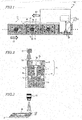
- FIG. 1 is an upper plan view schematically showing the pouring cup position detection system 100 being installed in a casting line CL
- FIG. 2 is a cross-sectional view taken along line 2A - 2A' in FIG. 1 .
- Each mold M includes a main mold body 1 having a pouring cup 1g formed therein, a flask (which herein is a metal flask) 1F , and a weight 2 .
- the main mold body 1 is a sand mold, with a cavity formed therein.
- the main mold body 1 is located within the metal flask 1F .
- the main mold body 1 is not limited to a sand mold, but may be any of various molds for casting methods which perform gravity pouring. For example, it may be a mold made of ceramic particles, or a mold made of metal particles.
- the cavity of the main mold body 1 is composed of a sprue 1a , runners 1b , risers 1c , and a product portion 1d .
- a weight 2 is placed on the main mold body 1 .
- the weight 2 has an opening 2a , and is disposed so that the pouring cup 1g of the main mold body 1 is exposed through the opening 2a (i.e., so that the pouring cup 1g overlaps the opening 2a ).
- the weight 2 is placed on the main mold body 1 so as to be clear of the pouring cup 1g in planar perspective.
- the pouring cup position detection system 100 detects the position of the pouring cup 1g (which typically is the center position of the pouring cup 1g ) of a mold M .
- the pouring cup position detection system 100 includes: an image processing device 10 , which in turn includes an imager (digital camera) 12 ; and at least one marker 20 that is provided on the mold M and positioned relative to the pouring cup 1g .
- the pouring cup position detection system 100 i.e., the part thereof excluding the marker (s) 20
- the pouring cup position detection system 100 is able to move in a direction D2 , which is opposite to the direction D1 of conveyance of the mold M . Therefore, the imager 12 is able to move relatively to the mold M .
- a plurality of (or more specifically, two) markers 20 are provided for one mold M .
- the markers 20 are situated on the weight 2 .
- the image processing device 10 includes a calculation section 14 .
- the calculation section 14 is typically a computer (e.g., a panel computer).
- the image processing device 10 may further include an illuminator which is not shown.
- the imager 12 captures an image containing the markers 20 . Based on the image which has been captured by the imager 12 (i.e., an image containing the markers 20 ), the image processing device 10 generates information concerning the position of the pouring cup 1g (hereinafter referred to also as "pouring cup position information"). Generation of the pouring cup position information occurs as predetermined image processing is applied to the image containing the markers 20 .
- pouring cup position information is generated based on the image containing the markers 20 , whereby the position of the pouring cup 1g of the mold M can be accurately detected.
- one possible technique might be to capture an image containing the pouring cup 1g , and directly detect the position of the pouring cup 1g from that image.
- such a technique may not be able to accurately detect the position of the pouring cup 1g .
- spills of melt around the pouring cup 1g may be visible in the image, thus lowering the accuracy of detecting the position of the pouring cup 1g .
- pouring cup position information is generated based on an image containing the markers 20 , which are positioned relative to the pouring cup 1g ; therefore, the position of the pouring cup 1g is detectable as a relative position based on the positions of the markers 20 .
- the position of the pouring cup 1g can be detected more accurately than by a technique of imaging the pouring cup 1g .
- the number of markers 20 is not limited thereto. There may be one marker 20 , or three or more markers 20 . However, a plurality of markers 20 will enable more accurate detection of the position of the pouring cup 1g than does one marker 20 . Moreover, three or more markers 20 will enable more accurate detection of the position of the pouring cup 1g than do two markers 20 .
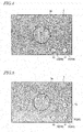
- FIG. 4 is an upper plan view, in the case where two markers 20 are used, showing relative positioning between the opening 2a of the weight 2 and the two markers 20 .
- the marker 20A that is located relatively to the right is referred to as the first marker
- the marker 20B that is located relatively to the left is referred to as the second marker.
- a coordinate system is envisaged where, given a certain point as an origin, an x axis is defined by an axis extending along the right-left direction from the origin (the right side of the origin being positive, the left side negative), and a y axis is defined by an axis extending along the top-bottom direction from the origin (the upper side of the origin being positive, the lower side negative).
- the center of the opening 2a is designated as P0 (x 0 , y 0 ); the center of the first marker 20A as P1 (x 1 , y 1 ); and the center of the second marker 20B as P2 (x 2 , y 2 ).
- an angle ⁇ counterclockwise being positive
- the angle ⁇ is expressed by eq. (1) below, and the coordinates (x 0 , y 0 ) of the center P0 of the opening 2a are expressed by eqs. (2) and (3) below.
- the distance R and the angle ⁇ can be determined in advance by using a positioning jig 24 described later, for example.
- FIG. 5 is an upper plan view, in the case where three markers 20 (a first marker 20A , a second marker 20B , and a third marker 20C ) are used, showing relative positioning of the opening 2a of the weight 2 and the three markers 20 .
- any two markers 20 may be selected from among the three or more markers 20 , and similarly to the method which has been described with reference to FIG. 4 , coordinates (x 0 , y 0 ) of the center P0 of the opening 2a may be calculated with respect to that pair (i.e., two markers 20 ).
- coordinates (x 0 , y 0 ) of the center P0 of the opening 2a as many times as there are pairs (combinations) of two such markers 20 (e.g., three in the case of using three markers 20 ), and taking a mean value of the calculated values, the detection accuracy can be enhanced.
- the coordinates (x 0 , y 0 ) of the center P0 of the opening 2a can still be calculated even if the other marker(s) 20 cannot be imaged well for soiling or other causes.
- the position of the pouring cup 1g can be calculated in the following manner, for example.
- ⁇ x and ⁇ y can be determined in advance by using a positioning jig 24 described below, for example. Therefore, by applying image processing to an image containing one marker 20 to determine the coordinates (x 1 , y 1 ) of the center P1 thereof, it is possible to calculate the coordinates (x 0 , y 0 ) of the center P0 of the opening 2a , i.e., the position of the center of the pouring cup 1g .
- planar markers 20 are formed through application of a heat-resistant paint, or attaching sheets of heat-resistant material.
- the markers 20 are preferably white.
- the example shown in FIG. 6 has an advantage of being able to form the markers 20 easily.
- the markers 20 are planar (i.e., having substantially zero thickness), the markers 20 are likely to be soiled by spills of melt in the example shown in FIG. 6 .
- the markers 20 are cylindrical marker pieces which are made of a heat-resistant material (e.g. iron).
- the example shown in FIG. 7 has an advantage in the markers 20 are less likely to be soiled by spills of melt.
- the height (thickness) of the markers 20 in the form of marker pieces is not particularly limited, it is preferably 25 mm or more from the standpoint of unlikeliness of soiling.
- FIGS. 8(a) and (b) are an upper plan view and a perspective view showing an example of more detailed construction of a marker 20 in the form of a marker piece.
- the marker 20 has a white upper face 20u, and that the marker 20 has a matte-black side face 20s .
- the marker 20 has a diameter d1 of e.g. 30 mm.
- the marker 20 has a height h1 of e.g. 30 mm.
- the marker 20 is attached to the weight 2 with a bolt 21, for example.
- a protection member 22 is provided so as to surround each marker 20 .
- a cylindrical protection member 22 is disposed on the outside of each cylindrical marker 20 .
- the protection member 22 is made of a heat-resistant material (e.g. iron).
- the protection member 22 prevents spills of melt from sticking to the markers 20 , thus better preventing soiling of the marker 20 by spills of melt.
- FIGS. 10(a) and (b) are an upper plan view and a side view showing an example of more detailed construction of the protection member 22 .
- the entire protection member 22 is matte black.
- the protection member 22 includes a cylindrical base portion 22a and a semicylindrical collar portion 22b provided on the base portion 22a .
- the protection member 22 is to be disposed so that the collar portion 22b is located on the side of the marker 20 facing the pouring cup 1g (i.e., facing the opening 2a ).
- the base portion 22a has an outer diameter d2 of e.g.
- the collar portion 22b has an inner diameter d3 of e.g. 48 mm.
- the base portion 22a has a height h2 of e.g. 25 mm, and the collar portion 22b has a height h3 of e.g. 10 mm.
- the coloration of the marker 20 and the protection member 22a is not limited to the above example, the coloration is preferably one that maximizes the contrast between the marker 20 (or the upper face 20u of the marker 20 ) and its surroundings.
- FIG. 6 to FIG. 10 show cases where the shape of each marker 20 (i.e., a planar shape of the marker 20) appears circular when viewed in the direction of image capturing (i.e., parallel to the center axis of the opening 2 ); however, the planar shape of the marker 20 is not limited to circular, but may be any arbitrary shape.
- the planar shape of the marker 20 may be rectangular.
- FIG. 11 shows an example where marker pieces which are shaped in quadrangular prisms are provided as markers 20 . Even if the markers 20 have a planar shape other than a circular shape, the center position of the opening 2a can be calculated by extracting the centroid point, or an edge, of the marker 20 .
- the positions of the markers 20 on the weight 2 are not limited to those shown in the figures above.
- the markers 20 may be disposed at arbitrary positions 20P on the weight 2 as shown in FIG. 12 , for example. However, preferably all disposed markers 20 are capable of being imaged through a single capturing.
- the markers 20 can be positioned relative to the pouring cup 1g by using a positioning jig 24 shown in FIG. 13 , for example.
- the positioning jig 24 has at least one (e.g., plural as shown herein) opening formed in a predetermined position(s).
- the positioning jig 24 has a first opening 24a corresponding to the opening 2a of the weight 2 and a second opening 24b corresponding to a marker 20 .
- FIGS. 14(a) and (b) and FIGS. 15(a) and (b) are diagrams showing a positioning method using the positioning jig 24 .
- a plug (lid) 26 made of resin is fitted in the opening 2a of the weight 2 .
- the plug 26 has a disk shape.
- the positioning jig 24 is placed on the weight 2 so that the first opening 24a fits around the plug 26 .
- the marker 20 is fitted in the second opening 24b of the positioning jig 24 , and fixed with the bolt 21 .
- This produces a weight 2 as shown in FIG. 15(b) , having a marker 20 attached thereon which is positioned relative to the opening 2a (i.e., relative to the pouring cup 1g ).
- the positioning jig 24 facilitates positioning of the marker 20 with respect to a plurality of molds 1 (i.e., a plurality of weights 2 ).
- the plug 26 can also be used for calibrating the position of the opening 2a of the weight 2 . From an image which is captured with the imager 12 while the positioning jig 24 is placed on the weight 2 (i.e., on the mold M ), coordinates (x 0 , y 0 ) of the center P0 of the opening 2a can be determined, and by using these resultant (x 0 , y 0 ), the aforementioned R, ⁇ , ⁇ x, ⁇ y can be obtained.
- the positioning jig 24 itself is positioned relative to the weight 2 by the plug 26 ; however, the positioning jig 24 may be positioned relative to the weight 2 (or the mold M ) by means of any structure, including constructions other than the illustrated construction. Therefore, the positioning jig 24 does not need to have an opening formed corresponding to the opening 2a of the weight 2 , and may at least have an opening(s) which is formed corresponding to the marker(s) 20 . Therefore, in the case where there is one marker 20 , only one opening may be formed.
- the markers 20 does not need to be provided on the weight 2 so long as they are positioned relative to the pouring cup 1g .
- the markers 20 may be provided at arbitrary positions 20P on the metal flask (flask) 1F of the mold M .
- FIGS. 17(a) and (b) show an example of specific construction of the imager 12 .
- FIGS. 17(a) and (b) are a side view and a lower plan view schematically showing the imager 12 .
- the imager 12 is connected to a communication cable 13 , so that an image which is captured by the imager 12 is output to the calculation section 14 via the communication cable 13 .
- a dust cover 15 and a light-shielding cover 16 are attached on the imager 12 .
- the dust cover 15 prevents dust from attaching to a lens 12a of the imager 12 .
- the light-shielding cover 16 restricts light that enters the imager 12 .
- the light-shielding cover 16 is disposed so as to partially cover the lens 12a when the imager 12 is viewed from below.
- the light-shielding cover 16 restrains light sources around the imager 12 from exerting unfavorable influences (disturbance) on image capturing.
- the position of the pouring cup 1g of the mold M can be detected accurately.
- the pouring cup position detection system 100 can be suitably used for a casting apparatus.
- FIG. 18 shows a casting apparatus 200 including the pouring cup position detection system 100 .
- FIG. 18 is a block diagram schematically showing the casting apparatus 200 .
- the casting apparatus 200 includes the pouring cup position detection system 100 , a pouring machine 110 , and a pressurizing device 120 .
- the casting apparatus 200 further includes a control device 130 .
- the pouring machine 110 pours melt into the mold M through the pouring cup 1g .
- the pouring machine 110 There is no particular limitation as to the construction of the pouring machine 110 .
- Various types of pouring machines can be used as the pouring machine 110 , e.g., an automatic pouring machine of the type that tilts a ladle.
- a ladle-tilting type automatic pouring machine includes a ladle, a ladle tilting mechanism for tilting the ladle, and the like.
- the pressurizing device 120 feeds at least particulate matter through the pouring cup 1g .
- the pressurizing device 120 includes a nozzle portion which sends out particulate matter, a moving mechanism which moves the nozzle portion, and a particulate matter supplier which supplies the particulate matter to the nozzle portion.
- the particulate matter is made of a heat-resistant material, and may be sand or steel balls, for example.
- the pressurizing device 120 blows the particulate matter into the mold M through the pouring cup 1g together with a gas (e.g., compressed air).
- a gas e.g., compressed air
- the control device 130 controls the operating timing, amount of motion, and the like of the pouring machine 110 and the pressurizing device 120 .
- the control device 130 is able to perform the aforementioned control based on information which is output from the image processing device 10 .
- the control device 130 is, for example, a programmable logic controller (PLC).
- the casting apparatus 200 is able to reduce the amount of melt to be poured into the mold M . This improves the pouring yield, and simplifies the processing work after the casting is released.
- the pressurizing device 120 carries out feeding of the particulate matter (i.e., blowing of the gas and particulate matter) based on the information concerning the position of the pouring cup 1g which is generated by the image processing device 10 (i.e., the position of the pouring cup 1g which is detected as relative position based on the position(s) of the marker(s) 20 ).
- the nozzle portion can be accurately located above the pouring cup 1g , thus to suitably perform feeding of the particulate matter. It also prevents the nozzle portion from breaking by interfering with the metal flask (flask) 1F or the weight 2 of the mold M .
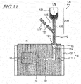
- the pressurizing device 120 includes a nozzle portion 121 , a moving mechanism 122 , and a particulate matter supplier 123 .
- the nozzle portion 121 is a portion which blows out (sends out) the gas and particulate matter 129 into the pouring cup 1g of the mold M .
- the moving mechanism 122 is able to move the nozzle portion 121 .
- the moving mechanism 122 is able to move the nozzle portion 121 along the right-left direction (i.e., a parallel direction to the direction of conveyance D1 of the mold M ), the front-rear direction (i.e., an orthogonal direction to the direction of conveyance D1 ) and the top-bottom direction.
- the specific construction of the moving mechanism 122 so long as it is capable of moving the nozzle portion 121 in the aforementioned manners; for example, servo motors for enabling movement along each of the right-left direction, the front-rear direction, and the top-bottom direction are encompassed.
- the particulate matter supplier 123 supplies the particulate matter 129 to the nozzle portion 121 .
- the particulate matter supplier 123 includes a particulate matter tank 124 which holds the particulate matter 129 , a particulate matter feed pipe 125 through which the particulate matter tank 124 and the nozzle portion 121 are allowed to communicate, and an open-close slide member 126 which is provided between the particulate matter tank 124 and the particulate matter feed pipe 125 .
- the particulate matter supplier 123 further includes a gas feed pipe 127 which is connected to the particulate matter feed pipe 125 , and an open-close valve 128 which is attached to the gas feed pipe 127 .
- the casting apparatus 200 is able to reduce the amount of melt to be poured into the mold M .
- the cavity of a mold is composed of a sprue, runners, risers, and a product portion (see FIG. 2 ).
- the melt is poured not only into the product portion, but also into the sprue, runners, and risers. Once the melt completes its solidification as the mold is cooled after melt pouring, the mold is broken apart in order to release the casting. At this time, the portion corresponding to the product portion is isolated and subjected to finishing, thus becoming a final product. The portions corresponding to the sprue, runners, and risers are redissolved as return material.
- pouring of the melt elsewhere other than the product portion i.e., the region of the cavity that corresponds to the actual product
- the product portion i.e., the region of the cavity that corresponds to the actual product
- excess pouring has also been a cause for increased processing work after the casting is released from the mold.
- the pressurizing device 120 feeds at least the particulate matter 129 into the mold M through the pouring cup 1g after the melt has been poured, the amount of melt to be poured into the sprue 1a and the runners 1b can be reduced. This improves the pouring yield, and simplifies the processing work after the casting is released.
- FIG. 20 shows a state immediately after melt m has been poured into the mold M (main mold body 1 ) through the pouring cup 1g .
- the volume of the poured melt m is smaller than the total volume of the cavity of the main mold body 1 , and substantially equal to the volume of the product portion 1d and the risers 1c (or, slightly greater than the volume of the product portion 1d and the risers 1c ).
- the nozzle portion 121 of the pressurizing device 120 is moved by the moving mechanism 122 (not shown in FIG. 21 ) to over the pouring cup 1g of the mold M which has finished pouring, and a gas G is blown from the nozzle portion 121 into the cavity of the main mold body 1 . Blowing of the gas G is performed by placing the open-close valve 128 , which is attached to the gas feed pipe 127 , in an open state. This pushes in the melt m so as to fill the product portion 1d and the risers 1c .
- the particulate matter 129 is fed into the cavity from the nozzle portion 121 .
- Feeding of the particulate matter 129 is performed by placing the open-close slide member 126 , which is provided between the particulate matter tank 124 and the particulate matter feed pipe 125 , in an open state.
- the open-close valve 128 also remains in an open state, so that the particulate matter 129 is blown in together with the gas G .
- FIG. 23 shows a state where blowing of the particulate matter 129 has been completed.
- the uppermost portion of the melt m is at a higher position than is its rearmost portion; therefore, a flowing force acts on the melt m to restore the state shown in FIG. 20 , but its flow is restrained by the frictional force due to the particulate matter 129 that has been blown in (i.e., a frictional force within particulate matter 129 and a frictional force between the particulate matter 129 and the inner surface of the cavity).
- the pressurizing device 120 by feeding the particulate matter 129 into the cavity with the pressurizing device 120 , the amount of melt to be poured into the sprue 1a and runners 1b can be reduced (substantially eliminated).
- the above example illustrates that the feeding of the particulate matter 129 is performed after blowing the gas G ; however, the gas G may be blown at the same time as feeding the particulate matter 129 , or after feeding the particulate matter 129 .
- a construction may be adopted such that the particulate matter 129 is pushed into the cavity by a pushing member (e.g., a rod of a pneumatic cylinder).
- a pushing member e.g., a rod of a pneumatic cylinder
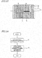
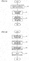
- FIG. 24 is a flowchart showing an exemplary pouring cup position detection method according to the present embodiment.
- an image containing at least one marker 20 that is positioned relative to the pouring cup 1g is captured (step S1 ).
- a more accurate detection of the position of the pouring cup 1g at this step S1 will be enabled by capturing an image containing a plurality of markers 20 (preferably three or more markers 20 ).
- step S2 image processing is applied to the image which was acquired at step S1 to generate information concerning the position of the pouring cup 1g (step S2 ). In this manner, the position of the pouring cup 1g of the mold M can be detected.
- pouring cup position information is generated based on an image containing a marker(s) 20 that is positioned relative to the pouring cup 1g ; therefore, the position of the pouring cup 1g can be detected as relative position with respect to the position(s) of the marker(s) 20 . This allows the position of the pouring cup 1g to be accurately detected.
- FIG. 25 is a flowchart showing another exemplary pouring cup position detection method according to the present embodiment.
- the positioning jig 24 is used to position at least one marker 20 relative to the pouring cup 1g (step S0 ).
- at least one (e.g., plural, in the example shown in FIG. 13 ) opening is formed at a predetermined position(s) of the positioning jig 24 .
- the marker(s) 20 can be easily positioned throughout a plurality of molds M .
- FIG. 26 is a flowchart showing an exemplary method of producing a casting according to the present embodiment.
- melt is poured into the mold M through the pouring cup 1g (step S11 ).
- information concerning the position of the pouring cup 1g is generated (step S12 ). This step S12 is executed by the aforementioned pouring cup position detection method.
- step S13 is executed based on the pouring cup position information generated at step S12 . Thereafter, when the melt completes its solidification, mold breaking and finishing are carried out (step S14 ). Thus, a casting is produced.
- the method of producing a casting according to the present embodiment includes step S13 of feeding particulate matter 129 to the mold M , into which the melt has been poured, through the pouring cup 1g .
- step S13 of feeding particulate matter 129 to the mold M , into which the melt has been poured, through the pouring cup 1g .
- the amount of melt to be poured into the mold M can be reduced.
- the pouring yield is improved, and the processing work after the casting is released can be simplified.
- this step S13 is performed based on information concerning the position of the pouring cup 1g which is generated by the image processing device, feeding of the particulate matter 129 can be suitably performed.
- melt pouring may be performed based on the pouring cup position information. Performing the melt pouring based on the pouring cup position information makes for more efficient or automated pouring work.
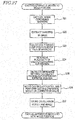
- FIG. 27 is a flowchart showing a more detailed example of position detection for the pouring cup 1g .
- the imager 12 captures an image containing the markers 20 , with an instruction from the control device 130 (step S21 ).
- markers 20 are extracted from within the captured image (step S22 ). Extraction of the marker 20 is performed by, for example, determining the color (brightness), shape, and size. At this time, any spills of melt (i.e., regions of largest brightness) within the image are excluded.
- the position of the pouring cup 1g (or the center position of the opening 2a of the weight 2 ) is calculated (step S23 ).
- an amount of translational motion of the position of the pouring cup 1g is calculated from one marker 20 in the pair, whereas an amount of rotational motion of the position of the pouring cup 1g is calculated from the other marker 20 (which is the technique described with reference to FIG. 4 ).
- any two arbitrary markers 20 are selected, calculation is provided for each such pair, and a mean value and variance are determined.
- step S24 plausibility of the calculated position of the pouring cup 1g (or the center position of the opening 2a of the weight 2 ) is determined (step S24 ). If the calculated position is not within the expected range, then it is deemed as a result of failure in the extraction of the markers 20 or movement of the casting apparatus 200 , and an error signal is output. In the case of three or more markers 20 , if the variance exceeds the expected range, an error signal may be output, or a mistake in the extraction of the markers 20 due to soiling of the markers 20 or the like may be recognized and only the calculation results for the pair(s) that can be deemed as having been correctly extracted may be used.
- step S25 a difference between the calculated position of the pouring cup 1g (or the center position of the opening 2a of the weight 2 ) and the expected position is calculated (step S25 ).
- the result of calculation is output as a correction value to the control device 130 .
- the casting apparatus 200 moves based on the correction value, and a casting operation is performed (step S26 ).
- step S27 the casting apparatus 200 is moved to the position of a next mold. In this manner, detection of the position of the pouring cup 1g and the subsequent casting operation can be executed.
- a pouring cup position detection system and a pouring cup position detection method that can accurately detect the position of a pouring cup of a mold are provided.
- the pouring cup position detection system and pouring cup position detection method according to embodiments of the present invention can be broadly used in casting methods which perform gravity pouring.
Landscapes
- Engineering & Computer Science (AREA)
- Mechanical Engineering (AREA)
- Image Analysis (AREA)
- Molds, Cores, And Manufacturing Methods Thereof (AREA)
- Length Measuring Devices By Optical Means (AREA)
Applications Claiming Priority (2)
| Application Number | Priority Date | Filing Date | Title |
|---|---|---|---|
| JP2014143997 | 2014-07-14 | ||
| PCT/JP2015/069905 WO2016009961A1 (ja) | 2014-07-14 | 2015-07-10 | 湯口位置検出システム、鋳造装置、湯口位置検出方法および鋳造品の製造方法 |
Publications (3)
| Publication Number | Publication Date |
|---|---|
| EP3170584A1 true EP3170584A1 (de) | 2017-05-24 |
| EP3170584A4 EP3170584A4 (de) | 2018-03-28 |
| EP3170584B1 EP3170584B1 (de) | 2019-05-08 |
Family
ID=55078455
Family Applications (1)
| Application Number | Title | Priority Date | Filing Date |
|---|---|---|---|
| EP15821561.6A Not-in-force EP3170584B1 (de) | 2014-07-14 | 2015-07-10 | Schaltpositions-erkennungssystem, gussvorrichtung, schaltpositions-erkennungsverfahren sowie verfahren zur herstellung eines gussproduktes |
Country Status (4)
| Country | Link |
|---|---|
| EP (1) | EP3170584B1 (de) |
| JP (1) | JP6053243B2 (de) |
| CN (1) | CN105531054B (de) |
| WO (1) | WO2016009961A1 (de) |
Cited By (1)
| Publication number | Priority date | Publication date | Assignee | Title |
|---|---|---|---|---|
| PL443671A1 (pl) * | 2023-02-01 | 2024-08-05 | Politechnika Śląska | Przystawka do zalewania kontaktowego |
Families Citing this family (7)
| Publication number | Priority date | Publication date | Assignee | Title |
|---|---|---|---|---|
| CN106042239B (zh) * | 2016-06-22 | 2018-01-02 | 厦门维克机械设备有限公司 | 一种多副不规则模具的全自动真空浇注方法 |
| CN106404039A (zh) * | 2016-08-31 | 2017-02-15 | 宁夏共享模具有限公司 | 一种铸件的检测方法和装置 |
| CN106767708A (zh) * | 2016-12-20 | 2017-05-31 | 陈志雄 | 一种基于图形识别的工业自控定位系统及其定位方法 |
| CN107168222A (zh) * | 2017-05-05 | 2017-09-15 | 应达工业(上海)有限公司 | 一种基于智能视觉相机的视频浇注系统 |
| CN109062161B (zh) * | 2018-08-23 | 2021-04-23 | 大连重工环保工程有限公司 | 一种倒罐站自动化出铁控制系统 |
| CN114612424B (zh) * | 2022-03-10 | 2025-02-28 | 苏州缔微致智能科技有限公司 | 一种模具浇口装夹的高精度定位方法及系统 |
| KR102681357B1 (ko) * | 2022-04-19 | 2024-07-03 | 건설기계부품연구원 | 플라스크 좌표 획득용 측정지그 및 이를 이용한 사형 주조용 주물사 자동 공급 시스템의 부피측정 방법 |
Family Cites Families (9)
| Publication number | Priority date | Publication date | Assignee | Title |
|---|---|---|---|---|
| JPS55145B2 (de) * | 1975-10-29 | 1980-01-05 | ||
| JPS5496434A (en) * | 1978-01-18 | 1979-07-30 | Kobe Steel Ltd | Method of centering molten steel injection flow |
| JPH04305358A (ja) * | 1991-04-02 | 1992-10-28 | Hitachi Metals Ltd | 堰折り装置 |
| ES2136808T3 (es) * | 1995-06-07 | 1999-12-01 | Inductotherm Corp | Sistema de posicionamiento de video para un recipiente de vertido. |
| JP2750677B2 (ja) * | 1995-12-11 | 1998-05-13 | 株式会社福山鋳造工場 | 自硬性鋳型による鋳物製造方法とその型枠 |
| JPH09225625A (ja) * | 1996-02-16 | 1997-09-02 | Hitachi Metals Ltd | 縦型無枠鋳造ラインの鋳物取り出し装置 |
| JP4888796B2 (ja) * | 2009-05-22 | 2012-02-29 | 有限会社ファンドリーテック・コンサルティング | 鋳造法 |
| EP2407261B1 (de) * | 2010-07-16 | 2016-04-20 | Primetals Technologies Austria GmbH | Verfahren zur automatischen Lageerkennung eines Ausgusses eines metallurgischen Gefäßes |
| CN101941067A (zh) * | 2010-08-26 | 2011-01-12 | 刘书僮 | 数控铁水浇铸系统 |
-
2015
- 2015-07-10 WO PCT/JP2015/069905 patent/WO2016009961A1/ja not_active Ceased
- 2015-07-10 CN CN201580001722.1A patent/CN105531054B/zh not_active Expired - Fee Related
- 2015-07-10 EP EP15821561.6A patent/EP3170584B1/de not_active Not-in-force
- 2015-07-10 JP JP2016506387A patent/JP6053243B2/ja active Active
Cited By (2)
| Publication number | Priority date | Publication date | Assignee | Title |
|---|---|---|---|---|
| PL443671A1 (pl) * | 2023-02-01 | 2024-08-05 | Politechnika Śląska | Przystawka do zalewania kontaktowego |
| PL246261B1 (pl) * | 2023-02-01 | 2024-12-23 | Odlewnia Rafamet Spolka Z Ograniczona Odpowiedzialnoscia | Przystawka do zalewania kontaktowego |
Also Published As
| Publication number | Publication date |
|---|---|
| CN105531054A (zh) | 2016-04-27 |
| CN105531054B (zh) | 2017-04-12 |
| WO2016009961A1 (ja) | 2016-01-21 |
| JP6053243B2 (ja) | 2016-12-27 |
| EP3170584A4 (de) | 2018-03-28 |
| EP3170584B1 (de) | 2019-05-08 |
| JPWO2016009961A1 (ja) | 2017-04-27 |
Similar Documents
| Publication | Publication Date | Title |
|---|---|---|
| EP3170584B1 (de) | Schaltpositions-erkennungssystem, gussvorrichtung, schaltpositions-erkennungsverfahren sowie verfahren zur herstellung eines gussproduktes | |
| JP5211923B2 (ja) | 切断装置及び切断方法 | |
| US20180365991A1 (en) | Traffic Light Recognition Device and Traffic Light Recognition Method | |
| WO2015114659A3 (en) | System and method for design analysis for metal casting design | |
| WO2006024091A8 (en) | A method for automated 3d imaging | |
| EP0747152B1 (de) | Videosystem zur Positionierung einer Giesspfanne | |
| CN106042239A (zh) | 一种多副不规则模具的全自动真空浇注方法 | |
| JP6451619B2 (ja) | 物体検出装置 | |
| MX2023002423A (es) | Sensor, sistema y metodo de medicion y maquina de moldeo. | |
| KR20190074172A (ko) | 용선 생산 설비에서 용융물 배출 속도 측정 방법 | |
| CN102445150A (zh) | 用于冶金容器浇口的自动位置识别的方法和测量装置 | |
| US20170217695A1 (en) | Systems and methods for transporting material | |
| CN105414480A (zh) | 一种铸型的柔性定位方法 | |
| JP6066785B2 (ja) | 混銑車炉体の鉄皮外面形状の測定方法 | |
| CN110072652B (zh) | 铸造设备的工作方法以及工作装置 | |
| More et al. | Review of casting defect analysis to initiate the improvement process | |
| JP2012200739A (ja) | 鋳枠の検査方法及びその検査に用いられる検査ユニット | |
| CN101378863A (zh) | 检验用于浇铸熔融金属的添加剂的流量的方法 | |
| JP5884179B2 (ja) | 溶融金属収容容器の検査装置及び検査方法 | |
| JPH09225625A (ja) | 縦型無枠鋳造ラインの鋳物取り出し装置 | |
| EP0951956B1 (de) | Verfahren und Vorrichtung zum Giessen in Sandformen | |
| US11020799B2 (en) | Marking method and marking device for casting | |
| KR101344580B1 (ko) | 코일 자동정렬 장치 | |
| Tiwari et al. | Semi automatic pouring system | |
| CN115301811A (zh) | 冲压装置及其动作控制方法 |
Legal Events
| Date | Code | Title | Description |
|---|---|---|---|
| STAA | Information on the status of an ep patent application or granted ep patent |
Free format text: STATUS: THE INTERNATIONAL PUBLICATION HAS BEEN MADE |
|
| PUAI | Public reference made under article 153(3) epc to a published international application that has entered the european phase |
Free format text: ORIGINAL CODE: 0009012 |
|
| STAA | Information on the status of an ep patent application or granted ep patent |
Free format text: STATUS: REQUEST FOR EXAMINATION WAS MADE |
|
| 17P | Request for examination filed |
Effective date: 20160726 |
|
| AK | Designated contracting states |
Kind code of ref document: A1 Designated state(s): AL AT BE BG CH CY CZ DE DK EE ES FI FR GB GR HR HU IE IS IT LI LT LU LV MC MK MT NL NO PL PT RO RS SE SI SK SM TR |
|
| AX | Request for extension of the european patent |
Extension state: BA ME |
|
| DAV | Request for validation of the european patent (deleted) | ||
| DAX | Request for extension of the european patent (deleted) | ||
| RIC1 | Information provided on ipc code assigned before grant |
Ipc: B22C 9/08 20060101ALI20180214BHEP Ipc: B22D 46/00 20060101ALI20180214BHEP Ipc: B22D 35/04 20060101AFI20180214BHEP Ipc: B22D 2/00 20060101ALI20180214BHEP Ipc: B22C 9/02 20060101ALI20180214BHEP Ipc: B22D 27/11 20060101ALI20180214BHEP Ipc: B22D 45/00 20060101ALI20180214BHEP Ipc: B22D 33/00 20060101ALI20180214BHEP |
|
| A4 | Supplementary search report drawn up and despatched |
Effective date: 20180222 |
|
| GRAP | Despatch of communication of intention to grant a patent |
Free format text: ORIGINAL CODE: EPIDOSNIGR1 |
|
| STAA | Information on the status of an ep patent application or granted ep patent |
Free format text: STATUS: GRANT OF PATENT IS INTENDED |
|
| INTG | Intention to grant announced |
Effective date: 20181203 |
|
| GRAS | Grant fee paid |
Free format text: ORIGINAL CODE: EPIDOSNIGR3 |
|
| GRAA | (expected) grant |
Free format text: ORIGINAL CODE: 0009210 |
|
| STAA | Information on the status of an ep patent application or granted ep patent |
Free format text: STATUS: THE PATENT HAS BEEN GRANTED |
|
| AK | Designated contracting states |
Kind code of ref document: B1 Designated state(s): AL AT BE BG CH CY CZ DE DK EE ES FI FR GB GR HR HU IE IS IT LI LT LU LV MC MK MT NL NO PL PT RO RS SE SI SK SM TR |
|
| REG | Reference to a national code |
Ref country code: GB Ref legal event code: FG4D |
|
| REG | Reference to a national code |
Ref country code: CH Ref legal event code: EP Ref country code: AT Ref legal event code: REF Ref document number: 1129408 Country of ref document: AT Kind code of ref document: T Effective date: 20190515 |
|
| REG | Reference to a national code |
Ref country code: DE Ref legal event code: R096 Ref document number: 602015030061 Country of ref document: DE |
|
| REG | Reference to a national code |
Ref country code: IE Ref legal event code: FG4D |
|
| REG | Reference to a national code |
Ref country code: NL Ref legal event code: MP Effective date: 20190508 |
|
| REG | Reference to a national code |
Ref country code: LT Ref legal event code: MG4D |
|
| PG25 | Lapsed in a contracting state [announced via postgrant information from national office to epo] |
Ref country code: LT Free format text: LAPSE BECAUSE OF FAILURE TO SUBMIT A TRANSLATION OF THE DESCRIPTION OR TO PAY THE FEE WITHIN THE PRESCRIBED TIME-LIMIT Effective date: 20190508 Ref country code: HR Free format text: LAPSE BECAUSE OF FAILURE TO SUBMIT A TRANSLATION OF THE DESCRIPTION OR TO PAY THE FEE WITHIN THE PRESCRIBED TIME-LIMIT Effective date: 20190508 Ref country code: SE Free format text: LAPSE BECAUSE OF FAILURE TO SUBMIT A TRANSLATION OF THE DESCRIPTION OR TO PAY THE FEE WITHIN THE PRESCRIBED TIME-LIMIT Effective date: 20190508 Ref country code: PT Free format text: LAPSE BECAUSE OF FAILURE TO SUBMIT A TRANSLATION OF THE DESCRIPTION OR TO PAY THE FEE WITHIN THE PRESCRIBED TIME-LIMIT Effective date: 20190908 Ref country code: NO Free format text: LAPSE BECAUSE OF FAILURE TO SUBMIT A TRANSLATION OF THE DESCRIPTION OR TO PAY THE FEE WITHIN THE PRESCRIBED TIME-LIMIT Effective date: 20190808 Ref country code: AL Free format text: LAPSE BECAUSE OF FAILURE TO SUBMIT A TRANSLATION OF THE DESCRIPTION OR TO PAY THE FEE WITHIN THE PRESCRIBED TIME-LIMIT Effective date: 20190508 Ref country code: FI Free format text: LAPSE BECAUSE OF FAILURE TO SUBMIT A TRANSLATION OF THE DESCRIPTION OR TO PAY THE FEE WITHIN THE PRESCRIBED TIME-LIMIT Effective date: 20190508 Ref country code: ES Free format text: LAPSE BECAUSE OF FAILURE TO SUBMIT A TRANSLATION OF THE DESCRIPTION OR TO PAY THE FEE WITHIN THE PRESCRIBED TIME-LIMIT Effective date: 20190508 Ref country code: NL Free format text: LAPSE BECAUSE OF FAILURE TO SUBMIT A TRANSLATION OF THE DESCRIPTION OR TO PAY THE FEE WITHIN THE PRESCRIBED TIME-LIMIT Effective date: 20190508 |
|
| PG25 | Lapsed in a contracting state [announced via postgrant information from national office to epo] |
Ref country code: BG Free format text: LAPSE BECAUSE OF FAILURE TO SUBMIT A TRANSLATION OF THE DESCRIPTION OR TO PAY THE FEE WITHIN THE PRESCRIBED TIME-LIMIT Effective date: 20190808 Ref country code: LV Free format text: LAPSE BECAUSE OF FAILURE TO SUBMIT A TRANSLATION OF THE DESCRIPTION OR TO PAY THE FEE WITHIN THE PRESCRIBED TIME-LIMIT Effective date: 20190508 Ref country code: RS Free format text: LAPSE BECAUSE OF FAILURE TO SUBMIT A TRANSLATION OF THE DESCRIPTION OR TO PAY THE FEE WITHIN THE PRESCRIBED TIME-LIMIT Effective date: 20190508 Ref country code: GR Free format text: LAPSE BECAUSE OF FAILURE TO SUBMIT A TRANSLATION OF THE DESCRIPTION OR TO PAY THE FEE WITHIN THE PRESCRIBED TIME-LIMIT Effective date: 20190809 |
|
| REG | Reference to a national code |
Ref country code: AT Ref legal event code: MK05 Ref document number: 1129408 Country of ref document: AT Kind code of ref document: T Effective date: 20190508 |
|
| PG25 | Lapsed in a contracting state [announced via postgrant information from national office to epo] |
Ref country code: EE Free format text: LAPSE BECAUSE OF FAILURE TO SUBMIT A TRANSLATION OF THE DESCRIPTION OR TO PAY THE FEE WITHIN THE PRESCRIBED TIME-LIMIT Effective date: 20190508 Ref country code: SK Free format text: LAPSE BECAUSE OF FAILURE TO SUBMIT A TRANSLATION OF THE DESCRIPTION OR TO PAY THE FEE WITHIN THE PRESCRIBED TIME-LIMIT Effective date: 20190508 Ref country code: RO Free format text: LAPSE BECAUSE OF FAILURE TO SUBMIT A TRANSLATION OF THE DESCRIPTION OR TO PAY THE FEE WITHIN THE PRESCRIBED TIME-LIMIT Effective date: 20190508 Ref country code: AT Free format text: LAPSE BECAUSE OF FAILURE TO SUBMIT A TRANSLATION OF THE DESCRIPTION OR TO PAY THE FEE WITHIN THE PRESCRIBED TIME-LIMIT Effective date: 20190508 Ref country code: DK Free format text: LAPSE BECAUSE OF FAILURE TO SUBMIT A TRANSLATION OF THE DESCRIPTION OR TO PAY THE FEE WITHIN THE PRESCRIBED TIME-LIMIT Effective date: 20190508 Ref country code: CZ Free format text: LAPSE BECAUSE OF FAILURE TO SUBMIT A TRANSLATION OF THE DESCRIPTION OR TO PAY THE FEE WITHIN THE PRESCRIBED TIME-LIMIT Effective date: 20190508 |
|
| REG | Reference to a national code |
Ref country code: DE Ref legal event code: R119 Ref document number: 602015030061 Country of ref document: DE |
|
| PG25 | Lapsed in a contracting state [announced via postgrant information from national office to epo] |
Ref country code: SM Free format text: LAPSE BECAUSE OF FAILURE TO SUBMIT A TRANSLATION OF THE DESCRIPTION OR TO PAY THE FEE WITHIN THE PRESCRIBED TIME-LIMIT Effective date: 20190508 Ref country code: MC Free format text: LAPSE BECAUSE OF FAILURE TO SUBMIT A TRANSLATION OF THE DESCRIPTION OR TO PAY THE FEE WITHIN THE PRESCRIBED TIME-LIMIT Effective date: 20190508 |
|
| REG | Reference to a national code |
Ref country code: CH Ref legal event code: PL |
|
| PLBE | No opposition filed within time limit |
Free format text: ORIGINAL CODE: 0009261 |
|
| STAA | Information on the status of an ep patent application or granted ep patent |
Free format text: STATUS: NO OPPOSITION FILED WITHIN TIME LIMIT |
|
| PG25 | Lapsed in a contracting state [announced via postgrant information from national office to epo] |
Ref country code: TR Free format text: LAPSE BECAUSE OF FAILURE TO SUBMIT A TRANSLATION OF THE DESCRIPTION OR TO PAY THE FEE WITHIN THE PRESCRIBED TIME-LIMIT Effective date: 20190508 |
|
| 26N | No opposition filed |
Effective date: 20200211 |
|
| REG | Reference to a national code |
Ref country code: BE Ref legal event code: MM Effective date: 20190731 |
|
| GBPC | Gb: european patent ceased through non-payment of renewal fee |
Effective date: 20190808 |
|
| PG25 | Lapsed in a contracting state [announced via postgrant information from national office to epo] |
Ref country code: PL Free format text: LAPSE BECAUSE OF FAILURE TO SUBMIT A TRANSLATION OF THE DESCRIPTION OR TO PAY THE FEE WITHIN THE PRESCRIBED TIME-LIMIT Effective date: 20190508 Ref country code: DE Free format text: LAPSE BECAUSE OF NON-PAYMENT OF DUE FEES Effective date: 20200201 |
|
| PG25 | Lapsed in a contracting state [announced via postgrant information from national office to epo] |
Ref country code: BE Free format text: LAPSE BECAUSE OF NON-PAYMENT OF DUE FEES Effective date: 20190731 Ref country code: CH Free format text: LAPSE BECAUSE OF NON-PAYMENT OF DUE FEES Effective date: 20190731 Ref country code: SI Free format text: LAPSE BECAUSE OF FAILURE TO SUBMIT A TRANSLATION OF THE DESCRIPTION OR TO PAY THE FEE WITHIN THE PRESCRIBED TIME-LIMIT Effective date: 20190508 Ref country code: LI Free format text: LAPSE BECAUSE OF NON-PAYMENT OF DUE FEES Effective date: 20190731 Ref country code: LU Free format text: LAPSE BECAUSE OF NON-PAYMENT OF DUE FEES Effective date: 20190710 |
|
| PG25 | Lapsed in a contracting state [announced via postgrant information from national office to epo] |
Ref country code: FR Free format text: LAPSE BECAUSE OF NON-PAYMENT OF DUE FEES Effective date: 20190731 |
|
| PG25 | Lapsed in a contracting state [announced via postgrant information from national office to epo] |
Ref country code: IE Free format text: LAPSE BECAUSE OF NON-PAYMENT OF DUE FEES Effective date: 20190710 |
|
| PG25 | Lapsed in a contracting state [announced via postgrant information from national office to epo] |
Ref country code: IT Free format text: LAPSE BECAUSE OF NON-PAYMENT OF DUE FEES Effective date: 20190710 Ref country code: GB Free format text: LAPSE BECAUSE OF NON-PAYMENT OF DUE FEES Effective date: 20190808 |
|
| PG25 | Lapsed in a contracting state [announced via postgrant information from national office to epo] |
Ref country code: CY Free format text: LAPSE BECAUSE OF FAILURE TO SUBMIT A TRANSLATION OF THE DESCRIPTION OR TO PAY THE FEE WITHIN THE PRESCRIBED TIME-LIMIT Effective date: 20190508 |
|
| PG25 | Lapsed in a contracting state [announced via postgrant information from national office to epo] |
Ref country code: IS Free format text: LAPSE BECAUSE OF FAILURE TO SUBMIT A TRANSLATION OF THE DESCRIPTION OR TO PAY THE FEE WITHIN THE PRESCRIBED TIME-LIMIT Effective date: 20190908 |
|
| PG25 | Lapsed in a contracting state [announced via postgrant information from national office to epo] |
Ref country code: MT Free format text: LAPSE BECAUSE OF FAILURE TO SUBMIT A TRANSLATION OF THE DESCRIPTION OR TO PAY THE FEE WITHIN THE PRESCRIBED TIME-LIMIT Effective date: 20190508 Ref country code: HU Free format text: LAPSE BECAUSE OF FAILURE TO SUBMIT A TRANSLATION OF THE DESCRIPTION OR TO PAY THE FEE WITHIN THE PRESCRIBED TIME-LIMIT; INVALID AB INITIO Effective date: 20150710 |
|
| PG25 | Lapsed in a contracting state [announced via postgrant information from national office to epo] |
Ref country code: MK Free format text: LAPSE BECAUSE OF FAILURE TO SUBMIT A TRANSLATION OF THE DESCRIPTION OR TO PAY THE FEE WITHIN THE PRESCRIBED TIME-LIMIT Effective date: 20190508 |