EP3169237B1 - Évaluation d'une sténose - Google Patents
Évaluation d'une sténose Download PDFInfo
- Publication number
- EP3169237B1 EP3169237B1 EP15738612.9A EP15738612A EP3169237B1 EP 3169237 B1 EP3169237 B1 EP 3169237B1 EP 15738612 A EP15738612 A EP 15738612A EP 3169237 B1 EP3169237 B1 EP 3169237B1
- Authority
- EP
- European Patent Office
- Prior art keywords
- blood vessel
- stenosis
- section
- image data
- hemodynamic
- Prior art date
- Legal status (The legal status is an assumption and is not a legal conclusion. Google has not performed a legal analysis and makes no representation as to the accuracy of the status listed.)
- Active
Links
- 208000031481 Pathologic Constriction Diseases 0.000 title claims description 66
- 230000036262 stenosis Effects 0.000 title claims description 66
- 208000037804 stenosis Diseases 0.000 title claims description 66
- 210000004204 blood vessel Anatomy 0.000 claims description 95
- 230000000004 hemodynamic effect Effects 0.000 claims description 38
- 238000003384 imaging method Methods 0.000 claims description 32
- 230000036772 blood pressure Effects 0.000 claims description 8
- 230000002966 stenotic effect Effects 0.000 claims description 8
- 238000002591 computed tomography Methods 0.000 claims description 7
- 238000004590 computer program Methods 0.000 claims description 6
- 238000002583 angiography Methods 0.000 claims description 5
- 230000011218 segmentation Effects 0.000 claims description 4
- 210000001367 artery Anatomy 0.000 description 33
- 210000002414 leg Anatomy 0.000 description 30
- 230000005855 radiation Effects 0.000 description 12
- 238000005259 measurement Methods 0.000 description 11
- 238000004088 simulation Methods 0.000 description 11
- 238000000034 method Methods 0.000 description 9
- 230000002792 vascular Effects 0.000 description 7
- 230000008901 benefit Effects 0.000 description 6
- 230000017531 blood circulation Effects 0.000 description 6
- 239000012530 fluid Substances 0.000 description 4
- 210000003484 anatomy Anatomy 0.000 description 3
- 230000000747 cardiac effect Effects 0.000 description 3
- 210000003090 iliac artery Anatomy 0.000 description 3
- 230000003902 lesion Effects 0.000 description 3
- 210000003205 muscle Anatomy 0.000 description 3
- 210000002254 renal artery Anatomy 0.000 description 3
- 210000001519 tissue Anatomy 0.000 description 3
- 238000013459 approach Methods 0.000 description 2
- 230000008321 arterial blood flow Effects 0.000 description 2
- 238000004364 calculation method Methods 0.000 description 2
- 210000001715 carotid artery Anatomy 0.000 description 2
- 230000000694 effects Effects 0.000 description 2
- 210000003414 extremity Anatomy 0.000 description 2
- 238000012014 optical coherence tomography Methods 0.000 description 2
- 238000011112 process operation Methods 0.000 description 2
- 230000009885 systemic effect Effects 0.000 description 2
- 210000003462 vein Anatomy 0.000 description 2
- 206010008479 Chest Pain Diseases 0.000 description 1
- 241000282412 Homo Species 0.000 description 1
- 208000004531 Renal Artery Obstruction Diseases 0.000 description 1
- 206010038378 Renal artery stenosis Diseases 0.000 description 1
- 210000000709 aorta Anatomy 0.000 description 1
- 210000000702 aorta abdominal Anatomy 0.000 description 1
- 230000003143 atherosclerotic effect Effects 0.000 description 1
- 230000002238 attenuated effect Effects 0.000 description 1
- 239000008280 blood Substances 0.000 description 1
- 210000004369 blood Anatomy 0.000 description 1
- 210000002302 brachial artery Anatomy 0.000 description 1
- 210000001736 capillary Anatomy 0.000 description 1
- 230000008859 change Effects 0.000 description 1
- 238000012512 characterization method Methods 0.000 description 1
- 239000003086 colorant Substances 0.000 description 1
- 238000013170 computed tomography imaging Methods 0.000 description 1
- 238000005094 computer simulation Methods 0.000 description 1
- 239000002872 contrast media Substances 0.000 description 1
- 230000001419 dependent effect Effects 0.000 description 1
- 238000001514 detection method Methods 0.000 description 1
- 238000003745 diagnosis Methods 0.000 description 1
- 238000002059 diagnostic imaging Methods 0.000 description 1
- 201000010099 disease Diseases 0.000 description 1
- 208000037265 diseases, disorders, signs and symptoms Diseases 0.000 description 1
- 210000001105 femoral artery Anatomy 0.000 description 1
- 210000002391 femur head Anatomy 0.000 description 1
- 231100001261 hazardous Toxicity 0.000 description 1
- 230000005802 health problem Effects 0.000 description 1
- 238000001727 in vivo Methods 0.000 description 1
- 238000007373 indentation Methods 0.000 description 1
- 238000002608 intravascular ultrasound Methods 0.000 description 1
- 210000004731 jugular vein Anatomy 0.000 description 1
- 210000003127 knee Anatomy 0.000 description 1
- 238000002595 magnetic resonance imaging Methods 0.000 description 1
- 230000003287 optical effect Effects 0.000 description 1
- 210000003049 pelvic bone Anatomy 0.000 description 1
- 238000001356 surgical procedure Methods 0.000 description 1
- 238000012285 ultrasound imaging Methods 0.000 description 1
- 230000000007 visual effect Effects 0.000 description 1
Images


Classifications
-
- A—HUMAN NECESSITIES
- A61—MEDICAL OR VETERINARY SCIENCE; HYGIENE
- A61B—DIAGNOSIS; SURGERY; IDENTIFICATION
- A61B6/00—Apparatus for radiation diagnosis, e.g. combined with radiation therapy equipment
- A61B6/52—Devices using data or image processing specially adapted for radiation diagnosis
- A61B6/5211—Devices using data or image processing specially adapted for radiation diagnosis involving processing of medical diagnostic data
- A61B6/5217—Devices using data or image processing specially adapted for radiation diagnosis involving processing of medical diagnostic data extracting a diagnostic or physiological parameter from medical diagnostic data
-
- A—HUMAN NECESSITIES
- A61—MEDICAL OR VETERINARY SCIENCE; HYGIENE
- A61B—DIAGNOSIS; SURGERY; IDENTIFICATION
- A61B6/00—Apparatus for radiation diagnosis, e.g. combined with radiation therapy equipment
- A61B6/02—Devices for diagnosis sequentially in different planes; Stereoscopic radiation diagnosis
- A61B6/03—Computerised tomographs
- A61B6/032—Transmission computed tomography [CT]
-
- A—HUMAN NECESSITIES
- A61—MEDICAL OR VETERINARY SCIENCE; HYGIENE
- A61B—DIAGNOSIS; SURGERY; IDENTIFICATION
- A61B6/00—Apparatus for radiation diagnosis, e.g. combined with radiation therapy equipment
- A61B6/48—Diagnostic techniques
- A61B6/481—Diagnostic techniques involving the use of contrast agents
-
- A—HUMAN NECESSITIES
- A61—MEDICAL OR VETERINARY SCIENCE; HYGIENE
- A61B—DIAGNOSIS; SURGERY; IDENTIFICATION
- A61B6/00—Apparatus for radiation diagnosis, e.g. combined with radiation therapy equipment
- A61B6/48—Diagnostic techniques
- A61B6/486—Diagnostic techniques involving generating temporal series of image data
- A61B6/487—Diagnostic techniques involving generating temporal series of image data involving fluoroscopy
-
- A—HUMAN NECESSITIES
- A61—MEDICAL OR VETERINARY SCIENCE; HYGIENE
- A61B—DIAGNOSIS; SURGERY; IDENTIFICATION
- A61B6/00—Apparatus for radiation diagnosis, e.g. combined with radiation therapy equipment
- A61B6/50—Clinical applications
- A61B6/504—Clinical applications involving diagnosis of blood vessels, e.g. by angiography
-
- A—HUMAN NECESSITIES
- A61—MEDICAL OR VETERINARY SCIENCE; HYGIENE
- A61B—DIAGNOSIS; SURGERY; IDENTIFICATION
- A61B6/00—Apparatus for radiation diagnosis, e.g. combined with radiation therapy equipment
- A61B6/50—Clinical applications
- A61B6/507—Clinical applications involving determination of haemodynamic parameters, e.g. perfusion CT
-
- G—PHYSICS
- G06—COMPUTING; CALCULATING OR COUNTING
- G06T—IMAGE DATA PROCESSING OR GENERATION, IN GENERAL
- G06T7/00—Image analysis
- G06T7/0002—Inspection of images, e.g. flaw detection
- G06T7/0012—Biomedical image inspection
-
- G—PHYSICS
- G06—COMPUTING; CALCULATING OR COUNTING
- G06T—IMAGE DATA PROCESSING OR GENERATION, IN GENERAL
- G06T7/00—Image analysis
- G06T7/0002—Inspection of images, e.g. flaw detection
- G06T7/0012—Biomedical image inspection
- G06T7/0014—Biomedical image inspection using an image reference approach
- G06T7/0016—Biomedical image inspection using an image reference approach involving temporal comparison
-
- G—PHYSICS
- G06—COMPUTING; CALCULATING OR COUNTING
- G06T—IMAGE DATA PROCESSING OR GENERATION, IN GENERAL
- G06T7/00—Image analysis
- G06T7/60—Analysis of geometric attributes
- G06T7/68—Analysis of geometric attributes of symmetry
-
- G—PHYSICS
- G16—INFORMATION AND COMMUNICATION TECHNOLOGY [ICT] SPECIALLY ADAPTED FOR SPECIFIC APPLICATION FIELDS
- G16H—HEALTHCARE INFORMATICS, i.e. INFORMATION AND COMMUNICATION TECHNOLOGY [ICT] SPECIALLY ADAPTED FOR THE HANDLING OR PROCESSING OF MEDICAL OR HEALTHCARE DATA
- G16H50/00—ICT specially adapted for medical diagnosis, medical simulation or medical data mining; ICT specially adapted for detecting, monitoring or modelling epidemics or pandemics
- G16H50/50—ICT specially adapted for medical diagnosis, medical simulation or medical data mining; ICT specially adapted for detecting, monitoring or modelling epidemics or pandemics for simulation or modelling of medical disorders
-
- G—PHYSICS
- G06—COMPUTING; CALCULATING OR COUNTING
- G06T—IMAGE DATA PROCESSING OR GENERATION, IN GENERAL
- G06T2207/00—Indexing scheme for image analysis or image enhancement
- G06T2207/10—Image acquisition modality
- G06T2207/10072—Tomographic images
- G06T2207/10081—Computed x-ray tomography [CT]
-
- G—PHYSICS
- G06—COMPUTING; CALCULATING OR COUNTING
- G06T—IMAGE DATA PROCESSING OR GENERATION, IN GENERAL
- G06T2207/00—Indexing scheme for image analysis or image enhancement
- G06T2207/10—Image acquisition modality
- G06T2207/10116—X-ray image
-
- G—PHYSICS
- G06—COMPUTING; CALCULATING OR COUNTING
- G06T—IMAGE DATA PROCESSING OR GENERATION, IN GENERAL
- G06T2207/00—Indexing scheme for image analysis or image enhancement
- G06T2207/30—Subject of image; Context of image processing
- G06T2207/30004—Biomedical image processing
- G06T2207/30101—Blood vessel; Artery; Vein; Vascular
Definitions
- the present invention generally relates to a system and a computer program for assessing a stenosis in a blood vessel in a body.
- a stenosis in a blood vessel obstructing blood flow through a patient's body may cause severe health problems to the patient. Medical treatment, catheter intervention, or even surgery might be necessary if severity of the stenosis is high and/or if the stenosis is at a particularly hazardous location. Therefore it is of high importance that a physician has sufficient and reliable data available about the stenosis location and severity.
- Degree of stenosis is the most used parameter for diagnosis. Hemodynamic severity of the stenosis may be functionally assessed by evaluating in-artery (catheterized) pressure or flow measurements, from which fractional flow reserve (FFR), pressure drop or stenotic resistance can be determined.
- FFR fractional flow reserve
- This invasive procedure requires precise and time consuming procedural work, costly catheters, as well as interventional risks since the stenosis needs to be passed with the catheter.
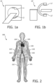
- non-invasive measurements using radiation imaging are known, e.g. using x-ray radiation imaging, such as, for example, computed tomography (CT) imaging (see Fig. 1a ), 2D x-ray angiography or (rotational) C-arm x-ray imaging (see Fig.
- CFD simulation uses a 3D segmentation obtained from CT or x-ray images and specific boundary conditions at the inlets (e.g. at or after the aorta) and outlets (e.g. at the drains to micro-vasculature).
- the boundary conditions are typically estimated from scaling laws, systemic parameters like the blood pressure measured at the extremities or an amount of muscle / tissue receiving the arterial blood flow. As the simulated FFR is sensitive to these boundary conditions, this approach may be unreliable in some cases.
- boundary conditions are, in known CFD models, usually estimated from previous pressure/flow measurements or CFD simulations of the same, or even a different, patient. These may however significantly deviate from an actual situation in the patient currently under examination.
- conditions may change per patient and over time. For instance, local geometries within the vascular system may be vastly different between different patients or may have changed over time within the same patient, possibly even (partly) due to the presence of the stenosis. Also, the conditions may have been determined at different moments in the cardiac cycle and/or there might have been a difference in the frequency, strength, etc. of the cardiac cycle itself may be different.
- WO03/071925 describes methods of generating an improved representation of an bood vessel to facilitate estimation of the degree of stenosis in blood vessels of subjects suffering from atherosclerotic disease.
- US 2012/053918 A1 discloses a patient-specific blood flow modelling system for planning treatment for patient suffering from e.g. chest pain with a computer system that determines a first fractional flow reserve within an anatomical structure of the patient based on a three-dimensional model and a physics-based model relating to the anatomical structure of the patient, that modifies the three-dimensional model, and that determines a second fractional flow reserve within the anatomical structure of the patient based on the modified three-dimensional model.
- Embodiments according to the present invention are directed to a system for assessing a stenosis in a blood vessel in a body according to claim 1.
- the invention also relates to a corresponding computer program product system for assessing stenosis severity in a blood vessel in a body.
- An advantage of the present invention is that use is made of image data of a second, simultaneously imaged and substantially symmetric blood vessel to improve the input that is presented to a physician to determine the stenosis severity.
- This input is more reliable since it uses additional image data that is not only very similar to that of the stenosed blood vessel, it is also taken at the same time and within the same patient, thereby eliminating interpatient or time-based differences.
- symmetry information between the first blood vessel and second blood vessel is determined on a per slice basis and the section of the second blood vessel corresponding to a section of the first blood vessel comprising the stenosis is selected based on said determined symmetry information. This allows for an improved comparison, since a selection of a section of the second blood vessel that corresponds more precisely with the stenosed area in the first blood vessel may be obtained.
- the hemodynamic properties relating to the section of the first blood vessel comprising the stenosis are at least partly determined from hemodynamic properties relating to the section of the second blood vessel corresponding to the section of the first blood vessel comprising the stenosis.
- one or more hemodynamic properties are selected from a group comprising fractional flow reserve, blood pressure drop and stenotic resistance. These are already commonly used and accepted properties for stenosis severity assessment.
- a further embodiment of the present invention is directed towards displaying the determined hemodynamic properties relating to the section of the first blood vessel comprising the stenosis. This provides the physician with the determined hemodynamic properties to assess the stenosis. Preferably the hemodynamic properties are displayed with respect to the relative length of the vessel. This allows for a more precise determination of stenosis characteristics.
- the determined hemodynamic properties relating to the section of the second blood vessel corresponding to the section of the first blood vessel comprising the stenosis may be displayed. This provides the physician with additional hemodynamic properties of a very similar blood vessel, with which the physician can compare those of the stenosed artery, which assists him further in assessing the severity of the stenosis.
- the determined hemodynamic properties relating to the section of the second blood vessel corresponding to the section of the first blood vessel comprising the stenosis is displayed mirrored. This facilitates comparison even more, since both blood vessels are shown in the same orientation. It will also allow for overlapped displaying both blood vessel, providing for an even closer visual comparison between the two blood vessels.
- the stenosed and corresponding arteries are imaged using non-invasive imaging means, preferably comprising an x-ray imaging device, such as computed tomography x-ray imaging device, 2D x-ray angiography or C-arm x-ray imaging device.
- x-ray imaging device such as computed tomography x-ray imaging device, 2D x-ray angiography or C-arm x-ray imaging device.
- X-ray imaging is available in almost every hospital and most modalities are capable of imaging a whole body.
- Particularly computed tomography and C-arm x-ray imaging are suitable to generate 3D images.
- a hemodynamic model preferably based on computational fluid dynamics simulation of blood flow is used to determine hemodynamic properties.
- These models are well-known and are suitable for the purposes of this invention. These models rely on input and in an embodiment of the present invention this input is provided by data available for the stenosed blood vessel, but is also, at least partly, by image data of the other, for instance non-stenosed, substantially symmetric blood vessel. This improves the input parameters and should result in a better modeling of the stenosed artery. This provides the physician with more reliable input to assess the stenosis severity.
- the other blood vessel may also have a stenosis. With the present invention the physician gains access to a relative lesion severity between both stenosed blood vessels.
- the present invention is particularly suitable for assessing a stenosis in leg blood vessels, arm blood vessels, carotid arteries and iliac arteries, but is certainly also suitable for other blood vessels for which a substantially symmetric counterpart is available.
- the invention may take form in various components and arrangements of components, and in various process operations and arrangements of process operations.
- the drawings are only for the purpose of illustrating preferred embodiments and are not to be construed as limiting the invention. To better visualize certain features may be omitted or dimensions may be not be according to scale.
- stenosis may represent any narrowing of a blood vessel, such as a legion, a vessel indentation, a (more or less) stationary clot and the like.
- the term blood vessel encompasses all parts of the vascular system of the human body that transport blood, including arteries, veins and capillaries; although in practice the present invention will most likely be most suitable and reliable for larger arteries and veins.
- the invention may be especially useful to blood vessels in the legs (such as the femoral arteries) 101, 101', iliac arteries 102, 102', blood vessels in the arms (such as the brachial arteries) 103, 103' and carotid arteries 104, 104', the locations in a body 100 of these are illustrated in Fig. 2 .
- the invention is also suitable for other blood vessels of which there are substantially symmetric pairs (e.g. renal arteries, jugular veins, etc.).
- the present invention would also be potentially be suitable for other, smaller blood vessels, as long as there is a substantially symmetric second blood vessel available.
- the invention is mostly illustrated using leg arteries as a non-limiting example, but it would be straightforward for a skilled person to adapt the boundary conditions and models of the present invention for other blood vessels in the body as well.
- the invention is further explained using radiation imaging, especially x-ray imaging, and in particular computed tomography, 2D x-ray angiography or (rotational) C-arm imaging, where use is made of a radiation source 11, 11' emitting radiation through an examination region towards a radiation detector 12, 12'.
- An object to be imaged such as a body comprising stenosed blood vessel, is moved through the examination region.
- the emitted radiation is attenuated in different levels by different body parts within the body and after detection it is processed and reconstructed into an image slice of the irradiated section of the body. This is repeated until the body, or at least the body part of interest, has fully passed through the examination region.
- the resulting series of image slices may be combined to construct a three-dimensional image of the body and its internal hard and soft body parts.
- the invention is certainly not limited to x-ray imaging, also other known radiation imaging methods could be used, such as magnetic resonance imaging, ultrasound imaging and others known in the art or combinations thereof.
- the invention is also suitable for use with non-radiation imaging methods, such as in-artery imaging like optical coherence tomography (OCT) or intravascular ultrasound (IVUS). Even though the advantages of non-invasive imaging may be lost, the other benefits of the invention will also be valid for non-invasive imaging.
- Figure 3a depicts a patient's body 100 that is moved through the examination region 13 between a radiation source 11, 11' and a radiation detector 12, 12' of an x-ray imaging device.
- the area of interest is a left leg 110 of the patient's body 100, since main left leg artery 101 comprises a stenosis 111 of which the exact location and severity are to be assessed.
- the examination region 13 is large enough to accommodate both the left leg 110 and the right leg 110', which are therefore both imaged simultaneously.
- the right leg 110' comprises a main artery 101' which is substantially symmetric to the main artery 101 of the right leg 110.
- substantially symmetric is to be understood in light of this invention as being symmetric when looked at it in broad view, discounting any obvious differences due to a human body never being completely symmetric (e.g. differences in leg length, thickness, muscle distribution, angles through the leg, etc). Obviously on a microscopic level any side branches are also not likely to occur on exactly the same positions along the main artery. Effectively, the main branches of both arteries should more or less overlap if they would be superimposed on each other. If no major deviations between the two arteries are present, especially at the section of interest, then the symmetry is sufficient for then purpose of this invention.
- the leg information symmetry can be further improved through comparison of information on a per slice basis.
- It may also include landmark based rigid registration, wherein said landmarks may be bony landmarks, e.g. the femur head or the knee.
- said angle of the pelvic bone relative to the axial slice may be used to correct for this.
- elastic registration may be used to correct for remaining asymmetries of the tissue and vessels.
- an image including the legs 110, 110' is constructed.
- This may be a three-dimensional image and all internal body parts may be shown.
- a two-dimensional image and/or ian image highlighting only specific body parts, such as an arterial system may be shown.
- Figure 3b shows such a reconstructed image. This is a two-dimensional image highlighting the arterial system, which is chosen for clarity to illustrate the present invention.
- the arterial system in figure 3b shows abdominal aorta 105, which splits of in the iliac arteries 102, 102', further descending into the main leg arteries 101, 101'.
- the position of stenosis 111 in the main left leg artery 101 may be precisely determined from the reconstructed image.
- stenosis assessment is commonly performed using in-artery, catheter-based measurements like pressure wires or flow measurements.
- the stenosis severity is determined by comparing values measured before (proximal to) and after (distal to) the stenosis.
- the stenosis severity is then calculated and quantified by hemodynamic properties such as FFR, pressure drop, stenotic resistance and others.
- the relative FFR is a commonly used measure of stenosis severity.
- the relative FFR is defined as the pressure distal to the stenosis relative to the pressure proximal the stenosis. For instance, an FFR of 0.85 means that the stenosis causes a 15% drop in blood pressure in the vessel.
- the relative FFR is therefore a very good property to reflect the stenosis severity.
- a physician may decide on treatment and a choose a specific treatment based on the FFR value (e.g. stenting of the artery when FFR is below 0.80).
- CSA cross-sectional areas
- the boundary conditions are typically estimated from scaling laws, systemic parameters such as the blood pressure measured at extremities or an amount of muscle in the legs receiving arterial blood flow.
- Global boundary conditions for the complete vascular system may be estimated or it may be limited to a segment of the vascular system, for instance just the leg artery or an even smaller section of said artery around the stenosis.
- ⁇ p ⁇ i w i h i ⁇ in which w i is an estimated weighting parameter.
- the final FFR value depends on both the proximal blood pressure p 0 and an amount of flow through the stenotic region.
- input parameters such as the weighting parameter w i
- the weighting factor w i for the stenosed artery 110 is at least partly determined from image data obtained at the same time and in the same body, namely from the substantially symmetric artery 10 1' that is present in the other leg 110'.
- Said other leg 110' was imaged simultaneously with the leg 110 comprising the stenosed artery 101 and is therefore obtained with exactly the same vascular and cardiac conditions, but without a stenosis, thereby making it a relevant input to determine input parameters for the CFD model and the subsequent calculation of the FFR for the stenosed artery 101 and/or it can be used as basis for a relevant comparison between the stenosed and non-stenosed arteries, improving the reliability for a physician determining stenosis severity.
- Other input parameters may be obtained from the other leg 110' as well and used in the modeling of the stenosed artery 101, for instance structural properties of the artery or a mean tissue mass from both legs may be used to estimate an outflow or a mean size of outlet vessels of the stenosed artery 101.
- the relative FFR values between the legs may be calculated with respect to slice position, 3D length of the blood vessel, estimated contrast agent bolus arrival time or other quantities to be extracted from the image data set or the flow simulation.
- the present invention uses already available data from a very similar vessel to improve the FFR calculation and/or to inform the physician of the differences between the stenosed and non-stenosed blood vessel. While this invention was explained using a simplified model, a skilled person would immediately know how to adapt this simplified model to different and more complex models and to other blood vessels that have a substantially symmetric counterpart within the same body.
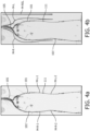
- the improved information may be presented to the physician in different ways. For instance, as is shown in Fig. 4a , measured values may be presented in relation to their position in the arteries. As an example, measured values (M-L-1, M-L-2) around the stenosis 111 in the main left leg artery 101 are shown together with measured values (M-R-1, M-R-2) of similar positions in the main right leg artery 101'. The measured values may be shown superimposed or separate from the image.
- An alternative way of presenting the information is shown in Fig. 4b , where the simulated measurement is presented as color coded lines M-R, M-L, M-REL, wherein different colors represent different values.
- color coded lines may shown for each leg, such as for instance the FFR for the left leg M-L and the FFR for the right leg M-R, presenting it along the contours of the vessels, as well as the relative FFR, for instance as a color coded sidebar M-REL.
- FFR for the left leg M-L
- FFR for the right leg M-R
- presenting it along the contours of the vessels as well as the relative FFR, for instance as a color coded sidebar M-REL.
- Numerous variations could easily be devised by the skilled person or combinations of each, optionally selectable by the physician, may be contemplated.
- FIG. 5 depicts a schematic representation of the method to assess a stenosis according to the present invention.
- a body comprising a blood vessel with a stenosis, as well as a substantially symmetric second blood vessel is imaged, for instance by radiation imaging.
- Hemodynamic properties for the non-stenosed blood vessel and stenosed blood vessel are determined in step 2 and 3 respectively. The hemodynamic properties for each separately may be determined by direct measurement or by simulation. Determination of the hemodynamic properties of the stenosed blood vessel may make use of properties determined for the non-stenosed blood vessel.
- the hemodynamic properties of the stenosed blood vessel are displayed. Preferably also the hemodynamic properties of the non-stenosed blood vessel are also displayed.
- hemodynamic properties may be displayed with respect to the relative length of the vessel, e.g. in between two bony landmarks or two vascular landmarks such as typical vessel branching points. in case that the vessels in both legs are not going along exactly the same path.
- the data can be mirrored in order to visually overlay them.
- the steps of the method of the present invention may be implemented as instructions for a computer program product.
- a computer program may be stored/distributed on a suitable medium, such as an optical storage medium or a solid-state medium supplied together with or as part of other hardware, but may also be distributed in other forms, such as via the Internet or other wired or wireless telecommunication systems. Any reference signs in the claims should not be construed as limiting the scope.
Landscapes
- Health & Medical Sciences (AREA)
- Engineering & Computer Science (AREA)
- Life Sciences & Earth Sciences (AREA)
- Medical Informatics (AREA)
- Physics & Mathematics (AREA)
- General Health & Medical Sciences (AREA)
- Nuclear Medicine, Radiotherapy & Molecular Imaging (AREA)
- Radiology & Medical Imaging (AREA)
- Public Health (AREA)
- Pathology (AREA)
- Biomedical Technology (AREA)
- Veterinary Medicine (AREA)
- Biophysics (AREA)
- High Energy & Nuclear Physics (AREA)
- Optics & Photonics (AREA)
- Heart & Thoracic Surgery (AREA)
- Molecular Biology (AREA)
- Surgery (AREA)
- Animal Behavior & Ethology (AREA)
- Theoretical Computer Science (AREA)
- Computer Vision & Pattern Recognition (AREA)
- General Physics & Mathematics (AREA)
- Quality & Reliability (AREA)
- Dentistry (AREA)
- Oral & Maxillofacial Surgery (AREA)
- Pulmonology (AREA)
- Physiology (AREA)
- Vascular Medicine (AREA)
- Data Mining & Analysis (AREA)
- Databases & Information Systems (AREA)
- Epidemiology (AREA)
- Primary Health Care (AREA)
- Geometry (AREA)
- Apparatus For Radiation Diagnosis (AREA)
Claims (3)
- Système pour évaluer la gravité d'une sténose dans un vaisseau sanguin dans un corps (100).
corps complet- un premier vaisseau sanguin (101) comprenant une sténose (111) ; et- un deuxième vaisseau sanguin (101') qui est sensiblement symétrique au premier vaisseau sanguin Navire, le système comprenant- des moyens d'imagerie non invasifs (11, 11', 12, 12') configurés pour générer simultanément des données d'image du premier vaisseau sanguin et du deuxième vaisseau sanguin ; et- Des moyens de détermination des propriétés hémodynamiques sont configurés pour :- déterminer les propriétés hémodynamiques par rapport à une section du deuxième vaisseau sanguin, qui correspond à la section du premier vaisseau sanguin présentant la sténose, à partir des données d'image du deuxième vaisseau sanguin ; et- Détermination des propriétés hémodynamiques concernant la section du premier vaisseau sanguin présentant la sténose à partir des données d'image du premier vaisseau sanguin à l'aide d'un modèle de propriétés hémodynamiques basé sur des paramètres d'entrée comprenant une segmentation 3D des données d'image et des données structurelles du premier vaisseau sanguin dérivées de celles-ci et des conditions aux limites aux entrées et sorties du premier vaisseau sanguin et dans lequel les paramètres d'entrée sont basés au moins en partie sur des propriétés dérivées des données d'image relatives à la partie du second vaisseau sanguin correspondant à la partie du premier vaisseau sanguin contenant la sténose; dans lequel le moyen pour déterminer les propriétés hémodynamiques est configuré pour générer une entrée pour évaluer les propriétés hémodynamiques liées à la partie du premier vaisseau sanguin comprenant la sténose sur la base des propriétés hémodynamiques déterminées liées à la partie du second vaisseau sanguin correspondant à la partie du le premier sang correspond au vaisseau avec la sténose, dans lequel une ou plusieurs propriétés hémodynamiques sont choisies dans un groupe constitué d'une réserve de débit fractionnaire, d'une chute de pression sanguine et d'une résistance à la sténose. - Système selon la revendication 1, dans lequel le moyen d'imagerie non invasif est
un appareil d'imagerie à rayons X, tel qu'un appareil d'imagerie à rayons X par tomodensitométrie, un appareil d'angiographie à rayons X 2D ou un appareil d'imagerie à rayons X à bras en C. - Produit de programme informatique pour évaluer une sténose dans un vaisseau sanguin dans un corps, le corps comprenant un premier vaisseau sanguin avec une sténose et un second vaisseau sanguin qui est sensiblement relativement symétrique au premier vaisseau sanguin, le produit de programme informatique étant exécuté sur l'ordinateur et comprend des instructions pour effectuer les étapes suivantes sur le système selon l'une quelconque des revendications 1 à 2 :- une imagerie non invasive (1) du premier vaisseau sanguin et du deuxième vaisseau sanguin simultanément pour obtenir des données d'image du premier vaisseau sanguin et des données d'image du deuxième vaisseau sanguin ;- déterminer (3) les propriétés hémodynamiques d'une section du deuxième vaisseau sanguin, qui correspond à une section du premier vaisseau sanguin présentant la sténose, à partir des données d'image du deuxième vaisseau sanguin,- déterminer (2) les propriétés hémodynamiques liées à la partie du premier vaisseau sanguin comprenant la sténose à partir des données d'image du premier vaisseau sanguin à l'aide d'un modèle de propriétés hémodynamiques basé sur des paramètres d'entrée, y compris une segmentation 3D des données d'image et des données structurelles de le premier vaisseau sanguin en est dérivé et les conditions aux limites aux entrées et sorties du premier vaisseau sanguin et dans lequel les paramètres d'entrée sont basés au moins en partie sur des propriétés dérivées des données d'image liées à la partie du second vaisseau sanguin correspondant à la partie de le premier vaisseau sanguin comprenant la sténose ; et- Génération de données de sténose sur la base des propriétés hémodynamiques déterminées par rapport à la section du premier vaisseau sanguin avec la sténose et sur les propriétés hémodynamiques déterminées par rapport à la section du second vaisseau sanguin correspondant à la section du premier vaisseau sanguin avec la sténose, une ou plusieurs propriétés hémodynamiques sont sélectionnées dans un groupe constitué d'une réserve de débit fractionnaire, d'une chute de pression sanguine et d'une résistance sténosée.
Applications Claiming Priority (2)
| Application Number | Priority Date | Filing Date | Title |
|---|---|---|---|
| EP14177627 | 2014-07-18 | ||
| PCT/EP2015/065950 WO2016008837A1 (fr) | 2014-07-18 | 2015-07-13 | Évaluation d'une sténose |
Publications (2)
| Publication Number | Publication Date |
|---|---|
| EP3169237A1 EP3169237A1 (fr) | 2017-05-24 |
| EP3169237B1 true EP3169237B1 (fr) | 2023-04-12 |
Family
ID=51211103
Family Applications (1)
| Application Number | Title | Priority Date | Filing Date |
|---|---|---|---|
| EP15738612.9A Active EP3169237B1 (fr) | 2014-07-18 | 2015-07-13 | Évaluation d'une sténose |
Country Status (6)
| Country | Link |
|---|---|
| US (1) | US10368819B2 (fr) |
| EP (1) | EP3169237B1 (fr) |
| JP (1) | JP6778174B2 (fr) |
| CN (1) | CN106572824B (fr) |
| RU (1) | RU2695262C2 (fr) |
| WO (1) | WO2016008837A1 (fr) |
Families Citing this family (14)
| Publication number | Priority date | Publication date | Assignee | Title |
|---|---|---|---|---|
| US8315812B2 (en) | 2010-08-12 | 2012-11-20 | Heartflow, Inc. | Method and system for patient-specific modeling of blood flow |
| CN108027966B (zh) * | 2015-09-02 | 2022-04-19 | 西门子保健有限责任公司 | 使用cfd仿真来减少4d dsa重构伪像的系统和方法 |
| WO2017199246A1 (fr) | 2016-05-16 | 2017-11-23 | Cathworks Ltd. | Sélection vasculaire à partir d'images |
| DE102016215976A1 (de) * | 2016-08-25 | 2018-03-01 | Siemens Healthcare Gmbh | Ermittelung einer klinischen Kenngröße mit einer Kombination unterschiedlicher Aufnahmemodalitäten |
| US20180192916A1 (en) * | 2017-01-10 | 2018-07-12 | General Electric Company | Imaging system for diagnosing patient condition |
| WO2018133118A1 (fr) | 2017-01-23 | 2018-07-26 | 上海联影医疗科技有限公司 | Système et procédé d'analyse de l'état de la circulation sanguine |
| CN107115108B (zh) * | 2017-04-27 | 2020-09-15 | 博动医学影像科技(上海)有限公司 | 快速计算血管压力差的方法及系统 |
| CN107411767B (zh) * | 2017-06-28 | 2020-10-16 | 西北工业大学 | 基于冠状动脉ct血管造影的狭窄病灶血流阻力计算方法 |
| EP3488774A1 (fr) * | 2017-11-23 | 2019-05-29 | Koninklijke Philips N.V. | Guide de mesure pour l'estimation du débit coronaire selon le principe de bernoulli |
| JP7167564B2 (ja) * | 2018-09-05 | 2022-11-09 | 株式会社島津製作所 | X線撮影装置およびx線撮影装置の作動方法 |
| CN109363699B (zh) * | 2018-10-16 | 2022-07-12 | 杭州依图医疗技术有限公司 | 一种乳腺影像病灶识别的方法及装置 |
| CN109875595B (zh) * | 2019-03-12 | 2021-02-09 | 数坤(北京)网络科技有限公司 | 一种颅内血管状态检测方法及装置 |
| US11432754B2 (en) * | 2019-09-24 | 2022-09-06 | Biosense Webster (Israel) Ltd. | Intracardiac electrocardiogram presentation |
| CN116649925B (zh) * | 2023-07-28 | 2023-10-31 | 杭州脉流科技有限公司 | 颅内动脉狭窄功能学评估的方法和装置 |
Citations (2)
| Publication number | Priority date | Publication date | Assignee | Title |
|---|---|---|---|---|
| WO2003071925A2 (fr) * | 2002-02-22 | 2003-09-04 | The Government Of The United States Of America As Represented By The Secretary Of The Department Of Health And Human Services | Amelioration de surfaces d'isointensite |
| US20120053918A1 (en) * | 2010-08-12 | 2012-03-01 | Heartflow, Inc. | Method and system for patient-specific modeling of blood flow |
Family Cites Families (24)
| Publication number | Priority date | Publication date | Assignee | Title |
|---|---|---|---|---|
| EP1181571B1 (fr) * | 1999-05-21 | 2008-12-17 | GE Healthcare AS | Procede d'imagerie par resonance magnetique |
| GB0221434D0 (en) | 2002-09-16 | 2002-10-23 | Houston John G | A method of analysing fluid flow in a conduit |
| WO2006061815A1 (fr) | 2004-12-08 | 2006-06-15 | Paieon Inc. | Procede et appareil de determination de parametres relatifs aux vaisseaux sanguins |
| IL165636A0 (en) | 2004-12-08 | 2006-01-15 | Paieon Inc | Method and apparatus for finding the coronary velocity and flow and related parameters |
| US8052611B2 (en) | 2007-03-14 | 2011-11-08 | Cardiac Pacemakers, Inc. | Method and apparatus for management of heart failure hospitalization |
| JP4945300B2 (ja) * | 2007-04-25 | 2012-06-06 | 株式会社東芝 | 超音波診断装置 |
| DE102008014792B3 (de) | 2008-03-18 | 2009-06-18 | Siemens Aktiengesellschaft | Verfahren und Vorrichtung zur Simulation eines Blutflusses in einem Gefäßabschnitt |
| US8200466B2 (en) | 2008-07-21 | 2012-06-12 | The Board Of Trustees Of The Leland Stanford Junior University | Method for tuning patient-specific cardiovascular simulations |
| WO2010022762A2 (fr) | 2008-08-25 | 2010-03-04 | ETH Zürich | Procédé, système et dispositif permettant d’optimiser des données de champ d’écoulement |
| EP2335171A2 (fr) * | 2008-09-30 | 2011-06-22 | Koninklijke Philips Electronics N.V. | Imagerie de perfusion |
| US20100125197A1 (en) * | 2008-11-18 | 2010-05-20 | Fishel Robert S | Method and apparatus for addressing vascular stenotic lesions |
| US20100130878A1 (en) | 2008-11-24 | 2010-05-27 | General Electric Company | Systems, apparatus and processes for automated blood flow assessment of vasculature |
| US9405886B2 (en) | 2009-03-17 | 2016-08-02 | The Board Of Trustees Of The Leland Stanford Junior University | Method for determining cardiovascular information |
| US20110307231A1 (en) | 2010-06-09 | 2011-12-15 | Jens Kirchner | Method and arrangement for creating an individualized, computer-aided model of a system, and a corresponding computer program and a corresponding machine-readable storage medium |
| US8682626B2 (en) | 2010-07-21 | 2014-03-25 | Siemens Aktiengesellschaft | Method and system for comprehensive patient-specific modeling of the heart |
| US8315812B2 (en) | 2010-08-12 | 2012-11-20 | Heartflow, Inc. | Method and system for patient-specific modeling of blood flow |
| US9119540B2 (en) | 2010-09-16 | 2015-09-01 | Siemens Aktiengesellschaft | Method and system for non-invasive assessment of coronary artery disease |
| DE102010043849B3 (de) | 2010-11-12 | 2012-02-16 | Siemens Aktiengesellschaft | Vorrichtung und Computertomograph zur Bestimmung und Darstellung der Durchblutung des Herzmuskels |
| JP5780748B2 (ja) * | 2010-12-15 | 2015-09-16 | 株式会社東芝 | 医用画像処理装置 |
| US20120296199A1 (en) * | 2011-03-21 | 2012-11-22 | New York University | Apparatus and Method of Non-Contrast Magnetic Resonance Angiography of Abdominal and Pelvic Arteries |
| US10186056B2 (en) | 2011-03-21 | 2019-01-22 | General Electric Company | System and method for estimating vascular flow using CT imaging |
| RU2457787C1 (ru) * | 2011-05-04 | 2012-08-10 | Государственное бюджетное образовательное учреждение высшего профессионального образования "Северо-Западный государственный медицинский университет имени И.И. Мечникова" Министерства здравоохранения и социального развития Российской Федерации (ГБОУ ВПО СЗГМУ им. И.И. Мечникова Минздравсоцразвития Ро | Способ диагностики поражения почек у детей |
| CN103764036B (zh) * | 2012-08-31 | 2016-11-16 | 东芝医疗系统株式会社 | 医用诊断图像处理装置 |
| US9675301B2 (en) * | 2012-10-19 | 2017-06-13 | Heartflow, Inc. | Systems and methods for numerically evaluating vasculature |
-
2015
- 2015-07-13 EP EP15738612.9A patent/EP3169237B1/fr active Active
- 2015-07-13 US US15/326,509 patent/US10368819B2/en active Active
- 2015-07-13 WO PCT/EP2015/065950 patent/WO2016008837A1/fr active Application Filing
- 2015-07-13 RU RU2017104807A patent/RU2695262C2/ru not_active IP Right Cessation
- 2015-07-13 JP JP2017502175A patent/JP6778174B2/ja active Active
- 2015-07-13 CN CN201580039183.0A patent/CN106572824B/zh active Active
Patent Citations (2)
| Publication number | Priority date | Publication date | Assignee | Title |
|---|---|---|---|---|
| WO2003071925A2 (fr) * | 2002-02-22 | 2003-09-04 | The Government Of The United States Of America As Represented By The Secretary Of The Department Of Health And Human Services | Amelioration de surfaces d'isointensite |
| US20120053918A1 (en) * | 2010-08-12 | 2012-03-01 | Heartflow, Inc. | Method and system for patient-specific modeling of blood flow |
Non-Patent Citations (2)
| Title |
|---|
| BOUDEWIJN G ET AL: "Isosurfaces as deformable models for magnetic resonance angiography", IEEE TRANSACTIONS ON MEDICAL IMAGING, IEEE SERVICE CENTER, PISCATAWAY, NJ, US, vol. 22, no. 7, 1 July 2003 (2003-07-01), pages 875 - 881, XP011099088, ISSN: 0278-0062, DOI: 10.1109/TMI.2003.815056 * |
| KAGADIS G C ET AL: "Computational representation and hemodynamic characterization of in vivo acquired severe stenotic renal artery geometries using turbulence modeling", MEDICAL ENGINEERING & PHYSICS, BUTTERWORTH-HEINEMANN, GB, vol. 30, no. 5, 1 June 2008 (2008-06-01), pages 647 - 660, XP022699306, ISSN: 1350-4533, Retrieved from the Internet <URL:https://www.sciencedirect.com/science/article/pii/S1350453307001427> [retrieved on 20080530], DOI: 10.1016/J.MEDENGPHY.2007.07.005 * |
Also Published As
| Publication number | Publication date |
|---|---|
| WO2016008837A1 (fr) | 2016-01-21 |
| JP2017524458A (ja) | 2017-08-31 |
| RU2017104807A3 (fr) | 2019-02-11 |
| EP3169237A1 (fr) | 2017-05-24 |
| CN106572824A (zh) | 2017-04-19 |
| CN106572824B (zh) | 2021-09-07 |
| JP6778174B2 (ja) | 2020-10-28 |
| RU2695262C2 (ru) | 2019-07-22 |
| RU2017104807A (ru) | 2018-08-20 |
| US20180206808A1 (en) | 2018-07-26 |
| US10368819B2 (en) | 2019-08-06 |
Similar Documents
| Publication | Publication Date | Title |
|---|---|---|
| EP3169237B1 (fr) | Évaluation d'une sténose | |
| US11481901B2 (en) | Medical image processing apparatus and medical image processing method | |
| EP3160335B1 (fr) | Appareil permettant de déterminer une valeur de réserve de débit fractionnaire | |
| US20170364658A1 (en) | Vascular flow assessment | |
| US8977339B1 (en) | Method for assessing stenosis severity through stenosis mapping | |
| US10111633B2 (en) | Local FFR estimation and visualisation for improved functional stenosis analysis | |
| US10052032B2 (en) | Stenosis therapy planning | |
| JP6484760B2 (ja) | 非侵襲的血流予備量比(ffr)に対する側副血流モデル化 | |
| JP7303260B2 (ja) | 動脈網における流量および圧力勾配を患者特定コンピュータ断層撮影アルゴリズムに基づくコントラスト分布から判断するための方法 | |
| EP3244790B1 (fr) | Tomodensitométrie ifr (instantanteous wave-free ratio) | |
| US10552958B2 (en) | Fractional flow reserve determination | |
| US20190076196A1 (en) | Vessel geometry and additional boundary conditions for hemodynamic ffr/ifr simulations from intravascular imaging | |
| Wang et al. | Functional assessment of stenotic coronary artery in 3D geometric reconstruction from fusion of intravascular ultrasound and X-ray angiography | |
| US10332255B2 (en) | Method for assessing stenosis severity in a lesion tree through stenosis mapping | |
| JP7426824B2 (ja) | 非侵襲的イメージングベースのffrのインタラクションモニタリング | |
| CN111357055A (zh) | 针对血管分叉估计流量以用于模拟血液动力学 |
Legal Events
| Date | Code | Title | Description |
|---|---|---|---|
| STAA | Information on the status of an ep patent application or granted ep patent |
Free format text: STATUS: THE INTERNATIONAL PUBLICATION HAS BEEN MADE |
|
| PUAI | Public reference made under article 153(3) epc to a published international application that has entered the european phase |
Free format text: ORIGINAL CODE: 0009012 |
|
| STAA | Information on the status of an ep patent application or granted ep patent |
Free format text: STATUS: REQUEST FOR EXAMINATION WAS MADE |
|
| 17P | Request for examination filed |
Effective date: 20170220 |
|
| AK | Designated contracting states |
Kind code of ref document: A1 Designated state(s): AL AT BE BG CH CY CZ DE DK EE ES FI FR GB GR HR HU IE IS IT LI LT LU LV MC MK MT NL NO PL PT RO RS SE SI SK SM TR |
|
| AX | Request for extension of the european patent |
Extension state: BA ME |
|
| DAV | Request for validation of the european patent (deleted) | ||
| DAX | Request for extension of the european patent (deleted) | ||
| STAA | Information on the status of an ep patent application or granted ep patent |
Free format text: STATUS: EXAMINATION IS IN PROGRESS |
|
| 17Q | First examination report despatched |
Effective date: 20180109 |
|
| RAP1 | Party data changed (applicant data changed or rights of an application transferred) |
Owner name: KONINKLIJKE PHILIPS N.V. |
|
| STAA | Information on the status of an ep patent application or granted ep patent |
Free format text: STATUS: EXAMINATION IS IN PROGRESS |
|
| GRAP | Despatch of communication of intention to grant a patent |
Free format text: ORIGINAL CODE: EPIDOSNIGR1 |
|
| STAA | Information on the status of an ep patent application or granted ep patent |
Free format text: STATUS: GRANT OF PATENT IS INTENDED |
|
| INTG | Intention to grant announced |
Effective date: 20221116 |
|
| GRAS | Grant fee paid |
Free format text: ORIGINAL CODE: EPIDOSNIGR3 |
|
| GRAA | (expected) grant |
Free format text: ORIGINAL CODE: 0009210 |
|
| STAA | Information on the status of an ep patent application or granted ep patent |
Free format text: STATUS: THE PATENT HAS BEEN GRANTED |
|
| AK | Designated contracting states |
Kind code of ref document: B1 Designated state(s): AL AT BE BG CH CY CZ DE DK EE ES FI FR GB GR HR HU IE IS IT LI LT LU LV MC MK MT NL NO PL PT RO RS SE SI SK SM TR |
|
| REG | Reference to a national code |
Ref country code: GB Ref legal event code: FG4D |
|
| REG | Reference to a national code |
Ref country code: CH Ref legal event code: EP |
|
| REG | Reference to a national code |
Ref country code: DE Ref legal event code: R096 Ref document number: 602015083144 Country of ref document: DE |
|
| REG | Reference to a national code |
Ref country code: IE Ref legal event code: FG4D |
|
| REG | Reference to a national code |
Ref country code: AT Ref legal event code: REF Ref document number: 1559363 Country of ref document: AT Kind code of ref document: T Effective date: 20230515 |
|
| REG | Reference to a national code |
Ref country code: DE Ref legal event code: R084 Ref document number: 602015083144 Country of ref document: DE |
|
| REG | Reference to a national code |
Ref country code: NL Ref legal event code: FP |
|
| REG | Reference to a national code |
Ref country code: LT Ref legal event code: MG9D |
|
| PGFP | Annual fee paid to national office [announced via postgrant information from national office to epo] |
Ref country code: NL Payment date: 20230726 Year of fee payment: 9 |
|
| REG | Reference to a national code |
Ref country code: AT Ref legal event code: MK05 Ref document number: 1559363 Country of ref document: AT Kind code of ref document: T Effective date: 20230412 |
|
| REG | Reference to a national code |
Ref country code: GB Ref legal event code: 746 Effective date: 20230921 |
|
| PG25 | Lapsed in a contracting state [announced via postgrant information from national office to epo] |
Ref country code: SE Free format text: LAPSE BECAUSE OF FAILURE TO SUBMIT A TRANSLATION OF THE DESCRIPTION OR TO PAY THE FEE WITHIN THE PRESCRIBED TIME-LIMIT Effective date: 20230412 Ref country code: PT Free format text: LAPSE BECAUSE OF FAILURE TO SUBMIT A TRANSLATION OF THE DESCRIPTION OR TO PAY THE FEE WITHIN THE PRESCRIBED TIME-LIMIT Effective date: 20230814 Ref country code: NO Free format text: LAPSE BECAUSE OF FAILURE TO SUBMIT A TRANSLATION OF THE DESCRIPTION OR TO PAY THE FEE WITHIN THE PRESCRIBED TIME-LIMIT Effective date: 20230712 Ref country code: ES Free format text: LAPSE BECAUSE OF FAILURE TO SUBMIT A TRANSLATION OF THE DESCRIPTION OR TO PAY THE FEE WITHIN THE PRESCRIBED TIME-LIMIT Effective date: 20230412 Ref country code: AT Free format text: LAPSE BECAUSE OF FAILURE TO SUBMIT A TRANSLATION OF THE DESCRIPTION OR TO PAY THE FEE WITHIN THE PRESCRIBED TIME-LIMIT Effective date: 20230412 |
|
| PGFP | Annual fee paid to national office [announced via postgrant information from national office to epo] |
Ref country code: IT Payment date: 20230721 Year of fee payment: 9 Ref country code: GB Payment date: 20230725 Year of fee payment: 9 |
|
| PG25 | Lapsed in a contracting state [announced via postgrant information from national office to epo] |
Ref country code: RS Free format text: LAPSE BECAUSE OF FAILURE TO SUBMIT A TRANSLATION OF THE DESCRIPTION OR TO PAY THE FEE WITHIN THE PRESCRIBED TIME-LIMIT Effective date: 20230412 Ref country code: PL Free format text: LAPSE BECAUSE OF FAILURE TO SUBMIT A TRANSLATION OF THE DESCRIPTION OR TO PAY THE FEE WITHIN THE PRESCRIBED TIME-LIMIT Effective date: 20230412 Ref country code: LV Free format text: LAPSE BECAUSE OF FAILURE TO SUBMIT A TRANSLATION OF THE DESCRIPTION OR TO PAY THE FEE WITHIN THE PRESCRIBED TIME-LIMIT Effective date: 20230412 Ref country code: LT Free format text: LAPSE BECAUSE OF FAILURE TO SUBMIT A TRANSLATION OF THE DESCRIPTION OR TO PAY THE FEE WITHIN THE PRESCRIBED TIME-LIMIT Effective date: 20230412 Ref country code: IS Free format text: LAPSE BECAUSE OF FAILURE TO SUBMIT A TRANSLATION OF THE DESCRIPTION OR TO PAY THE FEE WITHIN THE PRESCRIBED TIME-LIMIT Effective date: 20230812 Ref country code: HR Free format text: LAPSE BECAUSE OF FAILURE TO SUBMIT A TRANSLATION OF THE DESCRIPTION OR TO PAY THE FEE WITHIN THE PRESCRIBED TIME-LIMIT Effective date: 20230412 Ref country code: GR Free format text: LAPSE BECAUSE OF FAILURE TO SUBMIT A TRANSLATION OF THE DESCRIPTION OR TO PAY THE FEE WITHIN THE PRESCRIBED TIME-LIMIT Effective date: 20230713 |
|
| PGFP | Annual fee paid to national office [announced via postgrant information from national office to epo] |
Ref country code: FR Payment date: 20230725 Year of fee payment: 9 Ref country code: DE Payment date: 20230726 Year of fee payment: 9 |
|
| PG25 | Lapsed in a contracting state [announced via postgrant information from national office to epo] |
Ref country code: FI Free format text: LAPSE BECAUSE OF FAILURE TO SUBMIT A TRANSLATION OF THE DESCRIPTION OR TO PAY THE FEE WITHIN THE PRESCRIBED TIME-LIMIT Effective date: 20230412 |
|
| REG | Reference to a national code |
Ref country code: DE Ref legal event code: R097 Ref document number: 602015083144 Country of ref document: DE |
|
| PG25 | Lapsed in a contracting state [announced via postgrant information from national office to epo] |
Ref country code: SK Free format text: LAPSE BECAUSE OF FAILURE TO SUBMIT A TRANSLATION OF THE DESCRIPTION OR TO PAY THE FEE WITHIN THE PRESCRIBED TIME-LIMIT Effective date: 20230412 |
|
| PG25 | Lapsed in a contracting state [announced via postgrant information from national office to epo] |
Ref country code: SM Free format text: LAPSE BECAUSE OF FAILURE TO SUBMIT A TRANSLATION OF THE DESCRIPTION OR TO PAY THE FEE WITHIN THE PRESCRIBED TIME-LIMIT Effective date: 20230412 Ref country code: SK Free format text: LAPSE BECAUSE OF FAILURE TO SUBMIT A TRANSLATION OF THE DESCRIPTION OR TO PAY THE FEE WITHIN THE PRESCRIBED TIME-LIMIT Effective date: 20230412 Ref country code: RO Free format text: LAPSE BECAUSE OF FAILURE TO SUBMIT A TRANSLATION OF THE DESCRIPTION OR TO PAY THE FEE WITHIN THE PRESCRIBED TIME-LIMIT Effective date: 20230412 Ref country code: EE Free format text: LAPSE BECAUSE OF FAILURE TO SUBMIT A TRANSLATION OF THE DESCRIPTION OR TO PAY THE FEE WITHIN THE PRESCRIBED TIME-LIMIT Effective date: 20230412 Ref country code: DK Free format text: LAPSE BECAUSE OF FAILURE TO SUBMIT A TRANSLATION OF THE DESCRIPTION OR TO PAY THE FEE WITHIN THE PRESCRIBED TIME-LIMIT Effective date: 20230412 Ref country code: CZ Free format text: LAPSE BECAUSE OF FAILURE TO SUBMIT A TRANSLATION OF THE DESCRIPTION OR TO PAY THE FEE WITHIN THE PRESCRIBED TIME-LIMIT Effective date: 20230412 |
|
| PLBE | No opposition filed within time limit |
Free format text: ORIGINAL CODE: 0009261 |
|
| STAA | Information on the status of an ep patent application or granted ep patent |
Free format text: STATUS: NO OPPOSITION FILED WITHIN TIME LIMIT |
|
| PG25 | Lapsed in a contracting state [announced via postgrant information from national office to epo] |
Ref country code: MC Free format text: LAPSE BECAUSE OF FAILURE TO SUBMIT A TRANSLATION OF THE DESCRIPTION OR TO PAY THE FEE WITHIN THE PRESCRIBED TIME-LIMIT Effective date: 20230412 |
|
| PG25 | Lapsed in a contracting state [announced via postgrant information from national office to epo] |
Ref country code: MC Free format text: LAPSE BECAUSE OF FAILURE TO SUBMIT A TRANSLATION OF THE DESCRIPTION OR TO PAY THE FEE WITHIN THE PRESCRIBED TIME-LIMIT Effective date: 20230412 |
|
| REG | Reference to a national code |
Ref country code: CH Ref legal event code: PL |
|
| REG | Reference to a national code |
Ref country code: BE Ref legal event code: MM Effective date: 20230731 |
|
| 26N | No opposition filed |
Effective date: 20240115 |
|
| PG25 | Lapsed in a contracting state [announced via postgrant information from national office to epo] |
Ref country code: LU Free format text: LAPSE BECAUSE OF NON-PAYMENT OF DUE FEES Effective date: 20230713 |
|
| PG25 | Lapsed in a contracting state [announced via postgrant information from national office to epo] |
Ref country code: LU Free format text: LAPSE BECAUSE OF NON-PAYMENT OF DUE FEES Effective date: 20230713 |
|
| PG25 | Lapsed in a contracting state [announced via postgrant information from national office to epo] |
Ref country code: CH Free format text: LAPSE BECAUSE OF NON-PAYMENT OF DUE FEES Effective date: 20230731 |
|
| PG25 | Lapsed in a contracting state [announced via postgrant information from national office to epo] |
Ref country code: SI Free format text: LAPSE BECAUSE OF FAILURE TO SUBMIT A TRANSLATION OF THE DESCRIPTION OR TO PAY THE FEE WITHIN THE PRESCRIBED TIME-LIMIT Effective date: 20230412 |