EP3488774A1 - Guide de mesure pour l'estimation du débit coronaire selon le principe de bernoulli - Google Patents
Guide de mesure pour l'estimation du débit coronaire selon le principe de bernoulli Download PDFInfo
- Publication number
- EP3488774A1 EP3488774A1 EP17203207.0A EP17203207A EP3488774A1 EP 3488774 A1 EP3488774 A1 EP 3488774A1 EP 17203207 A EP17203207 A EP 17203207A EP 3488774 A1 EP3488774 A1 EP 3488774A1
- Authority
- EP
- European Patent Office
- Prior art keywords
- measurement position
- vessel
- interest
- hemodynamic
- intravascular
- Prior art date
- Legal status (The legal status is an assumption and is not a legal conclusion. Google has not performed a legal analysis and makes no representation as to the accuracy of the status listed.)
- Withdrawn
Links
Images


Classifications
-
- A—HUMAN NECESSITIES
- A61—MEDICAL OR VETERINARY SCIENCE; HYGIENE
- A61B—DIAGNOSIS; SURGERY; IDENTIFICATION
- A61B5/00—Measuring for diagnostic purposes; Identification of persons
- A61B5/02—Detecting, measuring or recording pulse, heart rate, blood pressure or blood flow; Combined pulse/heart-rate/blood pressure determination; Evaluating a cardiovascular condition not otherwise provided for, e.g. using combinations of techniques provided for in this group with electrocardiography or electroauscultation; Heart catheters for measuring blood pressure
- A61B5/026—Measuring blood flow
- A61B5/0285—Measuring or recording phase velocity of blood waves
-
- A—HUMAN NECESSITIES
- A61—MEDICAL OR VETERINARY SCIENCE; HYGIENE
- A61B—DIAGNOSIS; SURGERY; IDENTIFICATION
- A61B5/00—Measuring for diagnostic purposes; Identification of persons
- A61B5/02—Detecting, measuring or recording pulse, heart rate, blood pressure or blood flow; Combined pulse/heart-rate/blood pressure determination; Evaluating a cardiovascular condition not otherwise provided for, e.g. using combinations of techniques provided for in this group with electrocardiography or electroauscultation; Heart catheters for measuring blood pressure
- A61B5/02007—Evaluating blood vessel condition, e.g. elasticity, compliance
-
- A—HUMAN NECESSITIES
- A61—MEDICAL OR VETERINARY SCIENCE; HYGIENE
- A61B—DIAGNOSIS; SURGERY; IDENTIFICATION
- A61B34/00—Computer-aided surgery; Manipulators or robots specially adapted for use in surgery
- A61B34/10—Computer-aided planning, simulation or modelling of surgical operations
-
- A—HUMAN NECESSITIES
- A61—MEDICAL OR VETERINARY SCIENCE; HYGIENE
- A61B—DIAGNOSIS; SURGERY; IDENTIFICATION
- A61B5/00—Measuring for diagnostic purposes; Identification of persons
- A61B5/02—Detecting, measuring or recording pulse, heart rate, blood pressure or blood flow; Combined pulse/heart-rate/blood pressure determination; Evaluating a cardiovascular condition not otherwise provided for, e.g. using combinations of techniques provided for in this group with electrocardiography or electroauscultation; Heart catheters for measuring blood pressure
- A61B5/021—Measuring pressure in heart or blood vessels
- A61B5/0215—Measuring pressure in heart or blood vessels by means inserted into the body
-
- A—HUMAN NECESSITIES
- A61—MEDICAL OR VETERINARY SCIENCE; HYGIENE
- A61B—DIAGNOSIS; SURGERY; IDENTIFICATION
- A61B5/00—Measuring for diagnostic purposes; Identification of persons
- A61B5/02—Detecting, measuring or recording pulse, heart rate, blood pressure or blood flow; Combined pulse/heart-rate/blood pressure determination; Evaluating a cardiovascular condition not otherwise provided for, e.g. using combinations of techniques provided for in this group with electrocardiography or electroauscultation; Heart catheters for measuring blood pressure
- A61B5/026—Measuring blood flow
-
- A—HUMAN NECESSITIES
- A61—MEDICAL OR VETERINARY SCIENCE; HYGIENE
- A61B—DIAGNOSIS; SURGERY; IDENTIFICATION
- A61B6/00—Apparatus for radiation diagnosis, e.g. combined with radiation therapy equipment
- A61B6/50—Clinical applications
- A61B6/504—Clinical applications involving diagnosis of blood vessels, e.g. by angiography
-
- A—HUMAN NECESSITIES
- A61—MEDICAL OR VETERINARY SCIENCE; HYGIENE
- A61B—DIAGNOSIS; SURGERY; IDENTIFICATION
- A61B6/00—Apparatus for radiation diagnosis, e.g. combined with radiation therapy equipment
- A61B6/50—Clinical applications
- A61B6/507—Clinical applications involving determination of haemodynamic parameters, e.g. perfusion CT
-
- A—HUMAN NECESSITIES
- A61—MEDICAL OR VETERINARY SCIENCE; HYGIENE
- A61B—DIAGNOSIS; SURGERY; IDENTIFICATION
- A61B6/00—Apparatus for radiation diagnosis, e.g. combined with radiation therapy equipment
- A61B6/52—Devices using data or image processing specially adapted for radiation diagnosis
- A61B6/5211—Devices using data or image processing specially adapted for radiation diagnosis involving processing of medical diagnostic data
- A61B6/5217—Devices using data or image processing specially adapted for radiation diagnosis involving processing of medical diagnostic data extracting a diagnostic or physiological parameter from medical diagnostic data
-
- G—PHYSICS
- G06—COMPUTING; CALCULATING OR COUNTING
- G06T—IMAGE DATA PROCESSING OR GENERATION, IN GENERAL
- G06T7/00—Image analysis
- G06T7/10—Segmentation; Edge detection
- G06T7/11—Region-based segmentation
-
- G—PHYSICS
- G06—COMPUTING; CALCULATING OR COUNTING
- G06T—IMAGE DATA PROCESSING OR GENERATION, IN GENERAL
- G06T7/00—Image analysis
- G06T7/60—Analysis of geometric attributes
-
- G—PHYSICS
- G16—INFORMATION AND COMMUNICATION TECHNOLOGY [ICT] SPECIALLY ADAPTED FOR SPECIFIC APPLICATION FIELDS
- G16H—HEALTHCARE INFORMATICS, i.e. INFORMATION AND COMMUNICATION TECHNOLOGY [ICT] SPECIALLY ADAPTED FOR THE HANDLING OR PROCESSING OF MEDICAL OR HEALTHCARE DATA
- G16H30/00—ICT specially adapted for the handling or processing of medical images
- G16H30/40—ICT specially adapted for the handling or processing of medical images for processing medical images, e.g. editing
-
- G—PHYSICS
- G16—INFORMATION AND COMMUNICATION TECHNOLOGY [ICT] SPECIALLY ADAPTED FOR SPECIFIC APPLICATION FIELDS
- G16H—HEALTHCARE INFORMATICS, i.e. INFORMATION AND COMMUNICATION TECHNOLOGY [ICT] SPECIALLY ADAPTED FOR THE HANDLING OR PROCESSING OF MEDICAL OR HEALTHCARE DATA
- G16H50/00—ICT specially adapted for medical diagnosis, medical simulation or medical data mining; ICT specially adapted for detecting, monitoring or modelling epidemics or pandemics
- G16H50/20—ICT specially adapted for medical diagnosis, medical simulation or medical data mining; ICT specially adapted for detecting, monitoring or modelling epidemics or pandemics for computer-aided diagnosis, e.g. based on medical expert systems
-
- G—PHYSICS
- G16—INFORMATION AND COMMUNICATION TECHNOLOGY [ICT] SPECIALLY ADAPTED FOR SPECIFIC APPLICATION FIELDS
- G16H—HEALTHCARE INFORMATICS, i.e. INFORMATION AND COMMUNICATION TECHNOLOGY [ICT] SPECIALLY ADAPTED FOR THE HANDLING OR PROCESSING OF MEDICAL OR HEALTHCARE DATA
- G16H50/00—ICT specially adapted for medical diagnosis, medical simulation or medical data mining; ICT specially adapted for detecting, monitoring or modelling epidemics or pandemics
- G16H50/30—ICT specially adapted for medical diagnosis, medical simulation or medical data mining; ICT specially adapted for detecting, monitoring or modelling epidemics or pandemics for calculating health indices; for individual health risk assessment
-
- G—PHYSICS
- G16—INFORMATION AND COMMUNICATION TECHNOLOGY [ICT] SPECIALLY ADAPTED FOR SPECIFIC APPLICATION FIELDS
- G16H—HEALTHCARE INFORMATICS, i.e. INFORMATION AND COMMUNICATION TECHNOLOGY [ICT] SPECIALLY ADAPTED FOR THE HANDLING OR PROCESSING OF MEDICAL OR HEALTHCARE DATA
- G16H50/00—ICT specially adapted for medical diagnosis, medical simulation or medical data mining; ICT specially adapted for detecting, monitoring or modelling epidemics or pandemics
- G16H50/50—ICT specially adapted for medical diagnosis, medical simulation or medical data mining; ICT specially adapted for detecting, monitoring or modelling epidemics or pandemics for simulation or modelling of medical disorders
-
- A—HUMAN NECESSITIES
- A61—MEDICAL OR VETERINARY SCIENCE; HYGIENE
- A61B—DIAGNOSIS; SURGERY; IDENTIFICATION
- A61B34/00—Computer-aided surgery; Manipulators or robots specially adapted for use in surgery
- A61B34/10—Computer-aided planning, simulation or modelling of surgical operations
- A61B2034/101—Computer-aided simulation of surgical operations
- A61B2034/105—Modelling of the patient, e.g. for ligaments or bones
-
- A—HUMAN NECESSITIES
- A61—MEDICAL OR VETERINARY SCIENCE; HYGIENE
- A61B—DIAGNOSIS; SURGERY; IDENTIFICATION
- A61B6/00—Apparatus for radiation diagnosis, e.g. combined with radiation therapy equipment
- A61B6/02—Devices for diagnosis sequentially in different planes; Stereoscopic radiation diagnosis
- A61B6/03—Computerised tomographs
- A61B6/032—Transmission computed tomography [CT]
-
- A—HUMAN NECESSITIES
- A61—MEDICAL OR VETERINARY SCIENCE; HYGIENE
- A61B—DIAGNOSIS; SURGERY; IDENTIFICATION
- A61B6/00—Apparatus for radiation diagnosis, e.g. combined with radiation therapy equipment
- A61B6/48—Diagnostic techniques
- A61B6/486—Diagnostic techniques involving generating temporal series of image data
- A61B6/487—Diagnostic techniques involving generating temporal series of image data involving fluoroscopy
-
- G—PHYSICS
- G06—COMPUTING; CALCULATING OR COUNTING
- G06T—IMAGE DATA PROCESSING OR GENERATION, IN GENERAL
- G06T2207/00—Indexing scheme for image analysis or image enhancement
- G06T2207/30—Subject of image; Context of image processing
- G06T2207/30004—Biomedical image processing
- G06T2207/30101—Blood vessel; Artery; Vein; Vascular
Definitions
- the present invention relates to an apparatus for assessing a hemodynamic property in a coronary vasculature, a corresponding method and a respective computer program.
- the present invention relates to improved measurement guidance for performing measurements of hemodynamic parameters by deriving optimal measurement positions for intravascular measurements from diagnostic data of the vasculature.
- Functional stenosis severity in coronary arteries may typically be assessed by means of intravascular pressure measurements.
- assessment may particularly be performed by considering the ratio of the pressure distal the stenosis (P d ) to the pressure in the aorta (P a ).
- this ratio may be regarded using indices such as Fractional Flow Reserve (FFR) or instantaneous wave-Free Ratio (iFR), both of which are determined from said pressure ratio.
- FFR measurements use whole-cardiac cycle pressure traces and have to be performed in a state of hyperemia, typically induced by the administration of vasodilatory agents.
- iFR measurements are performed at rest during a specific period of the cardiac cycle, namely the diastole, which is also referred to as the wave-free period.
- CFR Coronary Flow Reserve
- an apparatus for assessing a coronary vasculature comprising an input unit for receiving diagnostic data of a vessel of interest in the vasculature and an identification unit for identifying, using the diagnostic data, a first measurement position, wherein a first hemodynamic value of a first hemodynamic property is derived at said first measurement position, and a second measurement position, wherein a second hemodynamic value of the first hemodynamic property is derived at said second measurement position.
- the apparatus further comprises a computation unit for computing, on the basis of the first hemodynamic value and the second hemodynamic value, at least one diagnostic parameter representative of a second hemodynamic property in the vessel of interest.
- the term vessel of interest may particularly refer to a vessel or vessel tree in the patient's coronary vasculature. Even more particularly, the term vessel of interest may refer to one or more vessel segments of the vessel of interest in the patient's vasculature.
- the term (first or second) hemodynamic property may generally refer to any property representative of the hemodynamics inside the patient's vasculature.
- hemodynamic value may refer to a measurement value of a hemodynamic property of the vasculature, whereby the hemodynamic value is acquired by a measurement at a particular intravascular position along a longitudinal axis of the vessel of interest.
- the hemodynamic properties may relate to properties such as vessel wall friction, vessel wall elasticity, vessel impedance, blood viscosity, blood pressure, flow velocity volumetric flow rate, volumetric outflow rate through vessel bifurcations or the like.
- a first and a second hemodynamic value may particularly be derived for a first hemodynamic property, such as the pressure inside the vessel of interest and, subsequently, be used to compute a diagnostic parameter that represents a second hemodynamic property, such as the volumetric flow rate.
- a first hemodynamic property may be used to derive a second hemodynamic property, different from the first hemodynamic property.
- diagnostic data may refer to any kind of measurement data representative of the vasculature including the vessel of interest. More particularly, diagnostic data may comprise diagnostic image data acquired by an imaging modality, such as X-ray scanning, computed tomography (CT), X-ray angiography, positron emission tomography (PET), single photon emission computed tomography (SPECT), ultrasound imaging, or the like.
- CT computed tomography
- PET positron emission tomography
- SPECT single photon emission computed tomography
- ultrasound imaging or the like.
- the diagnostic image data may hereby comprise a single two-dimensional or three-dimensional diagnostic image or a time series of diagnostic images collected over a certain time span.
- the diagnostic image data may relate to perfusion data obtained using magnetic resonance imaging (MRI), CT and/or PET.
- the diagnostic data may further comprise measurement data acquired by an intravascular measurement that has been performed in-situ, i.e. from inside the vessel of interest.
- the diagnostic data may comprise intravascular image data that has been acquired using an intravascular imaging modality, such as intravascular ultrasound (IVUS) and/or optical coherence tomography (OCT), obtained by a measurement device attached to a catheter that is introduced into the vessel of interest.
- IVUS intravascular ultrasound
- OCT optical coherence tomography
- the intravascular image data may comprise a single intravascular image or a time series of intravascular images collected for the same intravascular measurement position over time. Additionally or alternatively, the intravascular image data may also be collected by slowly pulling back the catheter through the vessel and by obtaining a plurality of intravascular images at a plurality of intravascular measurement positions.
- the diagnostic data may also comprise intravascular measurement data acquired during an intravascular measurement.
- This intravascular measurement data may particularly refer to pullback data.
- pullback data generally relates to a plurality of hemodynamic values determined at a plurality of intravascular positions along the longitudinal axis of a vessel of interest. Pullback data is obtained for a particular pullback length, which is defined as the distance between the starting position of the determination of the plurality of hemodynamic values and the ending position of this determination.
- the pullback data may for example be used to determine a pressure gradient along the vessel of interest, i.e. may be used to determine a plurality of pressure values for the plurality of intravascular positions, typically starting at a distal position and ending at a proximal position.
- proximal and distal shall be understood within their conventional meaning, i.e. as defining a position close and a position distant from the main mass of the body, respectively.
- a proximal position is a position closer to the heart and a distal position relates to a position more distant from the heart compared to the proximal position when viewed along a longitudinal axis of the coronary vessel.
- measurement position may generally refer to an intravascular position at which the hemodynamic value of the first hemodynamic property may be measured. It shall be understood that this measurement of the first hemodynamic property may be performed as part of the diagnostic data acquisition, e.g. in case the diagnostic data comprises (pressure) pullback data. Alternatively or additionally, the measurement of the first hemodynamic property may be performed in a further measurement step following the identification of the first and second measurement position using the diagnostic data.
- the deriving of the first and second hemodynamic value at the first and second measurement position particularly refers to determining, from the already acquired diagnostic data, the first and second hemodynamic value as measured at the identified first and second measurement position.
- the deriving of the first and second hemodynamic value refers to a situation where the first and second measurement position are identified from the diagnostic data and, subsequently, an (intravascular) measurement of the first hemodynamic property is performed at the first and second measurement position to measure the first and second hemodynamic value. Details of these different approaches will be described herein below in relation to the various embodiments.
- diagnostic data to identify the first and second measurement position allows to determine the optimum measurement positions for acquiring measurement values of the first hemodynamic property, whereby the values acquired at these positions allow for an improved approximation, i.e. computing, of a second hemodynamic property.
- the first hemodynamic property comprises a pressure in the vessel of interest.
- the hemodynamic value derived for the first hemodynamic property is an intravascular pressure value.
- pressure values are particularly suited for deriving further hemodynamic properties, such as flow properties. More particularly, blood flow properties may be derived from measured pressure values according to Bernoulli's principle.
- Q R A 1 A 2 2 ⁇ ⁇ ⁇ p R
- a 1 2 ⁇ A 2 2 ⁇ p H ⁇ p R .
- the pressure values have to be obtained at the first and second measurement position for both, the hyperemic as well as the resting state, respectively.
- flow-related hemodynamic properties may potentially be derived from a pressure measurements performed at least two measurement positions.
- the identifying the first measurement position and the second measurement position comprises predicting a localized change in the second hemodynamic property in the vessel of interest at least one candidate position, identifying said at least one candidate position as the first measurement position and identifying an intravascular position other than the at least one candidate position as the second measurement position.
- a flow property may be from pressure values obtained at a first and a second measurement position at which the pressure shows a significant difference. While these first and second measurement positions may typically be found in a particular vessel, or segment thereof, their identification is not straightforward. In some embodiments, the first and second measurement positions are thus identified on the basis of the diagnostic data.
- this second hemodynamic property may particularly relate to the flow velocity and the diagnostic data may be used to anticipate an increase or a decrease in the local flow velocity at a particular position along the longitudinal axis in the vessel of interest.
- the predicting may be performed in a variety of manners, depending on the kind of diagnostic data used.
- the predicting may particularly be performed by detecting, in the image data, a local change in the cross sectional area of the vessel of interest, e.g. due to a lesion and/or narrowing in the vessel of interest.
- a change of the cross sectional area of the vessel indicates a change in the flow velocity, since the same volume of blood has to pass a different cross sectional area.
- the flow velocity as the second hemodynamic property, will show a localized change, i.e. an increase or a decrease in value.
- the hemodynamic values may be used to predict changes in the values of the second hemodynamic property.
- the different hemodynamic properties are related to one another according to fluid dynamic laws. Hence, it is possible to derive, from pullback data which provides a plurality of values for the first hemodynamic property, at least one diagnostic parameter indicative of the second hemodynamic property.
- the pullback data may particularly comprise a plurality of pressure values acquired at a plurality of positions along the longitudinal axis of the vessel of interest starting at a distal position and ending at a proximal position.
- the first hemodynamic property may be related to the pressure inside the vessel of interest.
- the second hemodynamic property in this case may particularly be the flow velocity.
- the pressure and the flow velocity are related via Bernoulli's law and, thus, a change in the local flow velocity will also result in a change in pressure.
- a pressure pullback curve comprising a plurality of pressure values, local pressure changes, in particular local pressure decreases, may be identified. At the position of such a local pressure change, a change in flow velocity may be predicted.
- the position of said change in flow velocity may then be identified as a candidate position for the first measurement position, i.e. a position at which a first hemodynamic value may be determined which differs significantly from a second hemodynamic value measured at a second measurement position.
- the second measurement position is typically identified as a further intravascular position which is assumed to not be affected by the narrowing and/or lesion. Accordingly, the further intravascular position should be located far enough away from the narrowing and/or lesion so that no turbulences caused by the narrowing and/or lesion remains, while at the same time not being located too far away from the narrowing and/or lesion such that side effects such as friction losses and outflow to minor vessels become too significant to be neglected in the approximation.
- the further intravascular position may thus be considered an additional position inside the vessel at which the measurement of the second hemodynamic value may be performed, such that the second hemodynamic value differs significantly from the first hemodynamic value.
- This additional intravascular position may hereby be located proximal or distal to the candidate position.
- both, the first and the second measurement position may particularly be defined by the narrowing and/or lesion, with the candidate position identified as the first measurement position being located at the position of the narrowing and/or lesion, i.e. inside the narrowing and/or lesion, and the further intravascular position designated the second measurement position being positioned further away from it along the longitudinal axis of the vessel of interest.
- the further intravascular position in order to qualify as a suitable second measurement position, may particularly be distanced from the candidate position identified as the first measurement position by about 0.5 to 2 cm, more specifically 1 cm, along the longitudinal axis of the vessel of interest. Even more particularly, the further intravascular position may be located 1 cm proximal or distal from the narrowing and/or lesion and, thus, from the candidate position designated as the first measurement position.
- the identification of the second measurement position may also be performed using further and/or different criteria.
- a healthy looking vessel segment of the vessel of interest may be identified using respective diagnostic image data and/or intravascular image data.
- the term healthy particularly refers to the vessel segment not exhibiting any narrowing and/or lesions.
- the further intravascular measurement position may be located in this healthy looking vessel segment and, due to being located herein, be identified as the second measurement position.
- the pullback curve resulting from the pullback data may be regarded. If the pullback curve exhibits a constituent slope along a plurality of intravascular positions, this may be assumed as indicating a healthy vessel segment. An intravascular position located in the vessel segment may then be identified as the second measurement position.
- the identification of the second measurement position may be performed at least partially based on the presence and/or absence of bifurcations between the candidate position and the further intravascular position. More specifically, a further intravascular position may be identified as a second measurement position if there are no bifurcations present between the candidate position identified as the first measurement position and itself and may not be identified as the second measurement position if bifurcations are present in between the candidate position and the further intravascular measurement position.
- first and second measurement position By identifying the first and second measurement position in this manner, it may be ensured that the first and second hemodynamic value obtained at these positions differ significantly from one another. More specifically, choosing the first and second measurement position in this manner may allow to approximate the diagnostic parameter indicating the second hemodynamic property in spite of possible measurement accuracies.
- the diagnostic data comprises at least one diagnostic image of the vessel of interest.
- the identifying of the first measurement position and the second measurement position comprises segmenting the vessel of interest into a plurality of segments, deriving, for each of the segments, a plurality of geometric parameter values for the vessel of interest at a plurality of intravascular positions along a longitudinal axis of the vessel of interest and identifying, from the plurality of geometric parameter values at the plurality of intravascular positions, at least one geometric parameter value indicating a narrowing of the vessel of interest at least one candidate position from the plurality of intravascular positions, wherein the at least one candidate position of the narrowing is identified as the first measurement position and a further intravascular position other than the at least one candidate position is identified as the second measurement position.
- the identifying of the first and second measurement positions may be performed using at least one diagnostic image of the vasculature including the vessel of interest that has been obtained by a respective imaging modality such as X-ray scanning, computed tomography (CT), X-ray angiography, positron emission tomography (PET), single photon emission computed tomography (SPECT), ultrasound imaging, or the like.
- a respective imaging modality such as X-ray scanning, computed tomography (CT), X-ray angiography, positron emission tomography (PET), single photon emission computed tomography (SPECT), ultrasound imaging, or the like.
- CT computed tomography
- PET positron emission tomography
- SPECT single photon emission computed tomography
- ultrasound imaging or the like.
- the at least one diagnostic image may particularly refer to a single two-dimensional X-ray angiography image.
- the first and second measurement positions are first identified by considering the at least one diagnostic image. Subsequently, a measurement of the hemodynamic value, such as the pressure value, is performed at the thus identified first and second measurement position.
- the vessel of interest as imaged in the at least one diagnostic image is segmented into a plurality of segments. It shall be understood that the segmenting the vessel of interest corresponds to a segmenting of the vessel of interest as represented in the diagnostic image into respective vessel segments.
- a plurality of geometric parameter values for the vessel of interest may be derived at a plurality of intravascular positions.
- the term geometric parameter may refer to any parameter that is representative of the geometry of the vessel of interest.
- the geometric parameter may particularly refer to the cross sectional area of the vessel of interest.
- the geometric parameter may also refer to the inner shape of the vessel or similar geometric measures.
- a value for at least one geometric parameter, such as a value for the cross sectional area may be determined for a plurality of intravascular positions along the longitudinal axis of the vessel of interest.
- the plurality of geometric parameter values refers to the values determined respectively for each intravascular position along the longitudinal axis of the vessel of interest.
- the geometric parameter values are used to identify a lesion and/or a narrowing of the vessel of interest at least one intravascular position.
- the intravascular position at which the lesion and/or narrowing has been identified is then designated a candidate position, i.e. a potential candidate for the first measurement position.
- a candidate position i.e. a potential candidate for the first measurement position.
- one of these intravascular positions may be selected as the candidate position.
- the plurality of values for the geometric parameter indicating the geometry of the vessel are regarded and a change in the values is determined, which is indicative of a lesion and/or a narrowing in the vessel of interest.
- the cross sectional area is considered as the geometric parameter and a change in said cross sectional area is regarded as indicating the lesion and/or the narrowing.
- the intravascular position of the lesion and/or narrowing as identified from the at least one diagnostic image may be considered a possible candidate for the first measurement position.
- an additional intravascular position located proximal or distal to the thus identified candidate position may be considered and designated as second measurement position.
- the deriving of the first and second hemodynamic value of the first hemodynamic property is performed by measuring, at the first and second measurement position, the respective first hemodynamic property and acquiring the respective first and second value.
- the apparatus may further comprise a modeling unit for generating, on the basis of the at least one diagnostic image, a physiological model of the vessel of interest, the physiological model comprising a fluid dynamics model, wherein the computing the at least one diagnostic parameter representative of the second hemodynamic property is performed on the basis of the fluid dynamics model.
- a physiological model comprising a fluid dynamics model is used for computing the diagnostic parameter.
- the physiological model may be obtained from at least one diagnostic image of the vessel of interest.
- the physiological model may particularly be obtained from a single diagnostic image of the vessel of interest.
- the diagnostic image may hereby be used by a modeling unit to generate the physiological model from said diagnostic image.
- the generating of the physiological model may particularly comprise a segmentation of the imaged vessel of interest. This segmentation may be performed by the modeling unit for the purpose of generating the physiological model. Alternatively, the vessel segmentation performed by the identification unit for identifying the first and second measurement position may be used.
- a physiological model may be generated representing one or more vessel segments of the vessel of interest.
- the physiological model may comprise a fluid dynamics model to simulate the fluid dynamics, in particular of the blood, through the respective segments of the vessel of interest.
- the fluid dynamics model may be generated by performing calculations that simulate the interaction of the blood with the vessel wall, i.e. the inner surface of the vessel through which the blood is flowing. These interactions may be defined by respective boundary conditions that take account of certain hemodynamic properties of the vessel, such as vessel wall composition, vessel wall elasticity and vessel impedance, bifurcations in the vessel as well as blood viscosity.
- boundary conditions may be used which are similar for all patients or for particular patient groups (distinguished by age, gender, physiological condition or the like).
- patient-specific boundary conditions that have been derived for a particular patient may be used for calculation of the fluid dynamics model.
- the fluid dynamics model may particularly refer to a lumped parameter model.
- the fluid dynamics of the vessels are approximated by a topology of discrete entities. More particularly, in the lumped parameter model the vessel resistance is approximated by a series of resistor elements while the termination of a vessel is represented by an element representing ground.
- a vessel tree may be represented by a topology of resistors each having a particular resistance with the representation of the vessel tree being terminated by respective ground elements.
- the physiological model may also comprise a geometric model representing the geometric of the vessel of interest.
- the geometric model may hereby be a two-dimensional (2D) or three-dimensional (3D) geometric representation of the vessel of interest or a segment thereof.
- the geometric model may be a 2D model derived from 2D angiographic image data for which a third dimension is approximated by assuming a circular shape of the vessel.
- the geometry and the fluid dynamics through each vessel may be simulated using the geometric model and the fluid dynamics model comprised in the physiological model, respectively.
- the computing of the diagnostic parameter representative of the second hemodynamic property may be performed using the fluid dynamics model by simulating a second hemodynamic parameter in the vessel of interest on the basis of respective boundary conditions as derived e.g. from the diagnostic data and/or the first and second hemodynamic value.
- the identifying of the first measurement position and the second measurement position further comprises determining, on the basis of the diagnostic image, a location of a bifurcation in the vessel of interest, and excluding the further intravascular position when it is determined that the bifurcation is located at a location proximate the further intravascular position along the longitudinal axis of the vessel of interest.
- the above approach for computing the diagnostic parameter uses the approximation that no outflow of the blood from the vessel of interest occurs in the segment comprising the first and the second measurement position.
- the lesion and/or narrowing may be located in the proximity of bifurcations, i.e. a bifurcation may be identified proximal and/or distal to the lesion and/or narrowing.
- a bifurcation may be identified proximal and/or distal to the lesion and/or narrowing.
- part of the blood may outflow to (and inflow from) minor vessels, thereby resulting in a non-constant volumetric flow rate between the first measurement position and one or more intravascular positions that could be selected as the second measurement positions.
- the selection has to include an exclusion of such intravascular positions in order to still obtain an accurate approximation of the second hemodynamic property.
- the first and second measurement position should be selected such that no outflow to minor vessels occurs between the first and the second measurement position.
- the requirement that no outflow occurs shall be understood to also encompass the situation where the minor vessel (and the corresponding bifurcation) is small enough such that the outflow is neglectable from an accuracy point of view.
- the term proximate may particularly refer to the bifurcation being located at a position in between the candidate position selected as first measurement position and the further intravascular position regarded as a potential second measurement position.
- the at least one diagnostic image is used to identify vessel bifurcations along the vessel or vessel segment that is regarded for the assessment.
- the bifurcation may particularly be identified by deriving the bifurcation from the diagnostic image directly, either manually or by image processing, in case the bifurcation is directly visible in the diagnostic image.
- the bifurcation may also be identified on the basis of one or more geometric parameters that have been determined from the diagnostic image for each segment of the vessel of interest as described herein above. This identification may particularly be performed by regarding the geometric parameter values for a plurality of intravascular positions in each vessel (segment) to detect localized changes (i.e. increases or decreases) in said geometric parameter value, which may be considered indications for vessel bifurcations.
- this geometric parameter value may particularly be derived using an estimation based on the geometric model included in the physiological model.
- said at least one intravascular position may be excluded as a potential second measurement position. That is, the particular intravascular position is found to be unsuitable as second measurement position due to the bifurcation being proximate to the intravascular position and a different second measurement position may be identified. In case no suitable second measurement position may be found, the apparatus may then attempt to identify a different first measurement position. Alternatively or additionally, an outflow correction may be performed, correcting the approximation for the outflow through the bifurcation.
- the identifying of the first measurement position and the second measurement position further comprises a determining, on the basis of the diagnostic image, a location of a bifurcation in the vessel of interest proximate to the further intravascular position and the computing the at least one diagnostic parameter on the basis of the fluid dynamics model comprises a correcting of the at least one diagnostic parameter by simulating an outflow through said bifurcation using the fluid dynamics model.
- no exclusion of the second measurement position is performed in case of a bifurcation being present in between the first and the second measurement position. Rather, an approach is followed in which the computation of the second hemodynamic property is corrected such as to account for the outflow through the bifurcation.
- the local outflow rate ⁇ Q may particularly be modeled using the fluid dynamics model comprised in the physiological model. More specifically, the size and position of the bifurcation may be used as additional boundary conditions in the fluid dynamics model to simulate the outflow rate from the respective bifurcation.
- Q corresponds to the volumetric flow rate
- D is the vessel diameter
- k is a proportionality constant
- the local outflow rate ⁇ Q may be simulated as the difference between the thus determined values Q 1 , Q 2 .
- the fluid dynamics model may be a lumped parameter model and the outflow through the bifurcation may be estimated by means of a respective resistor element which outlet resistance is dependent on the size of the bifurcation as derived from the diagnostic image.
- the computing the at least one diagnostic parameter on the basis of the fluid dynamics model comprises a correcting of the at least one diagnostic parameter by simulating a vessel friction between the first measurement position and the second measurement position using the fluid dynamics model.
- the pressure loss between the first and the second measurement location due to friction may be considered in the computation of the second hemodynamic property. This may particularly be performed in case the pressure losses due to friction are too significant to be neglected in an accurate approximation of the diagnostic parameter representative of the second hemodynamic property.
- the pressure loss ⁇ p F has to be estimated. This may particularly be performed by including a respective boundary condition into the fluid dynamics model which simulates the pressure loss along the vessel of interest, including the pressure loss in between the first and second measurement position.
- the fluid dynamics model is implemented as a lumped parameter model
- the friction may be simulated by means of a respective resistor element.
- a finite element approach may alternatively be used.
- the diagnostic data comprises intravascular pullback data comprising a plurality of hemodynamic values of the first hemodynamic parameter acquired in-situ by means of a pullback recording at a plurality of intravascular positions along a longitudinal axis of the vessel of interest.
- the identifying of the first measurement position and the second measurement position comprises identifying, from the plurality of hemodynamic values acquired at the plurality of intravascular positions, at least one hemodynamic value exhibiting a localized change at least one candidate position from the plurality of intravascular positions, wherein the at least one candidate position is identified as the first measurement position and a further intravascular position other than the at least one candidate position is identified as the second measurement position.
- the diagnostic data may comprise pullback data that has been obtained in-situ from the vessel of interest.
- the pullback data may particularly refer to pressure pullback data.
- pullback data is acquired by pulling a measurement wire through a vessel of interest for a particular pullback length and acquiring a plurality of measurement values for a plurality of intravascular positions along said pullback length.
- the measurement device used may typically be a wire comprising a pressure probe. The pressure probe is then used to collect a plurality of pressure values at a plurality of intravascular positions, thereby resulting in a respective pressure pullback curve, i.e. curve representing the pressure values as a function of the intravascular position.
- a thus obtained pressure curve may exhibit a localized change, i.e. a localized increase or decrease in the pressure value at one or more particular intravascular positions.
- a change in pressure value
- a decrease in the pressure value causes an increase in flow velocity and vice versa.
- a localized change in the pressure value indicates a suitable candidate position for the first measurement position.
- each of the intravascular positions at which a localized change is detected may be used as the candidate position for the first measurement position.
- a further intravascular measurement position proximal or distal to the candidate position i.e. the first measurement position
- pressure pullback data to identify the first and second measurement position avoids the necessity of performing two measurements, one for identifying the measurement positions and one for deriving the first and second hemodynamic value. Rather, in this approach, the deriving of the first and second hemodynamic value may be directly performed on the already acquired pullback curve, by selecting the respective values of said curve for the first and second measurement position.
- the volumetric flow rate may not be determined from the pullback data alone.
- this embodiment may represent a straightforward approach for determining clinically relevant diagnostic parameters which do not require knowledge of the vessel geometry to be determined.
- the diagnostic data further comprises at least one diagnostic image of the vessel of interest. Further, the identifying of the first measurement position and the second measurement position comprises co-registering of the at least one diagnostic image to the intravascular pressure data, and indicating the first measurement position and the second measurement position in the at least one diagnostic image.
- the pressure pullback data may further be used to obtain a diagnostic parameter that requires the determination of a geometric parameter, such as the cross sectional area.
- the diagnostic data may further comprise at least one diagnostic image.
- the diagnostic image and the pullback data may be co-registered. Co-registering the diagnostic image and the pullback data refers to a process in which, for each or some of the intravascular positions of the pullback data, a corresponding vessel position in the diagnostic image of the vessel of interest is determined. Accordingly, the two measurement modalities are put in relation to one another.
- Such a co-registration allows to determine the vessel positions in the diagnostic image that correspond to the first and second measurement position identified from the pullback data. These vessel positions may then be indicated in the diagnostic image.
- the term indicating may particularly refer to a process internal the apparatus, in which the apparatus in provided with the information of which position in the imaged vessel corresponds to the first and second measurement position. On the basis of this indication, the apparatus may then perform a plurality of image processing steps or the like, to obtain information about the vessel geometry, and, accordingly, about the volumetric flow.
- the apparatus may particularly derive the cross sectional area at the first and second measurement position from the diagnostic image.
- the apparatus may employ the modeling unit to generate a physiological model for a vessel segment encompassing the first and second measurement position.
- This physiological model may comprise a fluid dynamics model and/or a geometric model.
- the apparatus may use the geometric model to derive the geometric parameter values, e.g. the cross sectional area, at least at the first and second measurement position.
- the apparatus may use the indication to generate a graphical representation of the imaged vessel including a first and/or a second indicator, such as an arrow or a circle, highlighting the first and second measurement position in the diagnostic image.
- the apparatus may then cause a display unit to display such graphical representation. This may allow a user, in particular a physician, to visually confirm a suitable selection of the first and second measurement position.
- the case where the diagnostic image is used to generate a graphical representation of the vessel of interest is not limited to the case where the diagnostic data comprises pullback data.
- the apparatus may generate a graphical representation of the imaged vessel in case the diagnostic data comprises image data.
- the apparatus may directly use this identification to insert the respective indicators into the graphical representation and provide the thus generated graphical representation to a respective display unit.
- This display unit may particularly comprise a computer screen, an LCD display or the like.
- the computing the at least one diagnostic parameter comprises a determining of a coronary flow reserve and/or a volumetric flow rate and/or flow velocity of the blood flow in the vessel of interest.
- the first and second hemodynamic value obtained at the first and second measurement position may particularly be used to compute a diagnostic parameter representative of the Coronary Flow Reserve (CFR), the volumetric flow rate Q, the flow velocity v or like hemodynamic properties.
- CFR Coronary Flow Reserve
- the computing may be performed particularly well in case the first hemodynamic property measured at the first and second measurement position relates to the pressure inside the vessel of interest.
- the pressure values allow for a computation of the flow-related properties according to respective fluid dynamics laws, such as Bernoulli's law, Murray's law and so on.
- a method for assessing a coronary vasculature comprises the steps of receiving diagnostic data of a vessel of interest in the vasculature for identifying, using the diagnostic data, a first measurement position, wherein a first hemodynamic value of a first hemodynamic property is derived at said first measurement position and a second measurement position, wherein a second hemodynamic value of the first hemodynamic property is derived at said second measurement position, and computing, on the basis of the first hemodynamic value and the second hemodynamic value, at least one diagnostic parameter representative of a second hemodynamic property in the vessel of interest.
- the method may further comprises that the identifying the first measurement position and the second measurement position comprises indicating, to a user, a first and second measurement position.
- the method further comprises a step in which the user is presented with the identified first and second measurement positions by means of a respective indication.
- This indication may particularly relate to a visual indication, by means of a graphical representation of the vessel of interest and respective indicators to the first and second measurement position.
- the indication may also be audible or visual in the sense that the position relative to the longitudinal axis of the vessel interest is indicated in spoken or written form.
- the user may then position the intravascular measurement device accordingly, in order to obtain the first hemodynamic value at the first measurement position and the second hemodynamic value at the second measurement position. That is, the user introduces the intravascular measurement device into the vessel of interest and adjusts the position such that the measurement probe, such as the pressure probe in case of a pressure measurement, is located at the first measurement position and, subsequently, at the second measurement position. It shall be understood that the intravascular measurement device may likewise first be positioned at the second measurement position and subsequently be moved to the first measurement position.
- the indicating to the user may further comprise other indications.
- these indications may particularly relate to further information of the vessel of interest and/or the procedure performed in order to assess it.
- the indicating may comprise providing information about the diagnostic measurement modality used to obtain the diagnostic data, providing information about the patient's health status and/or co-morbidities or the like.
- the indicating may particularly comprise an indicating that no first and/or second measurement position could be identified for a particular vessel (segment) of interest.
- a computer program for controlling an apparatus according to any of the above embodiments is provided, which, when executed by a processing unit, is adapted to perform the method according to one or more of its embodiments.
- a computer-readable medium having stored there on the computer program is provided.
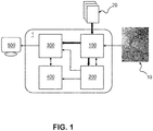
- Fig. 1 represents schematically an exemplary embodiment of an apparatus 1 for assessing a hemodynamic property.
- the apparatus 1 comprises an input unit 100, an identification unit 200, a computation unit 300, a modeling unit 400 and a display unit 500.
- the input unit 100 receives a diagnostic image 10 of a vessel of interest.
- diagnostic image 10 is a two-dimensional image acquired using X-ray angiography.
- the input unit 100 provides the diagnostic image 10 to the identification unit 200.
- the identification unit 200 is configured to receive the diagnostic image 10 and to perform a vessel segmentation of the vessel of interest represented in the diagnostic image 10, i.e. the identification unit 200 segments the (image of the) vessel of interest in a plurality of segments along a longitudinal axis of the vessel of interest.
- the identification unit 200 considers the segments and derives, for each intravascular position in each vessel segment, a value of one or more geometric parameters.
- one geometric parameter derived by the identification unit 200 is the cross sectional area of the vessel.
- the identification unit 200 thus derives for each intravascular position in a respective vessel segment, a corresponding cross sectional area of the vessel.
- the identification unit 200 may then determine an intravascular position at which a change in cross sectional area is observed.
- identification unit particularly determines an intravascular position at which a narrowing of the vessel is located.
- the identification unit 200 may compare the cross sectional area determined for each intravascular position in each segment and determine where the cross sectional area at one particular intravascular position in one particular segment is smaller compared to the remaining intravascular positions.
- the intravascular position exhibiting a smaller cross section is then designated as a candidate for the first measurement position. Subsequently, the candidate position is designated the first measurement position.
- the identification unit 200 then regards a further intravascular position other than the candidate position designated as the first measurement position and identifies this further intravascular position as the second measurement position.
- the further intravascular position corresponds to a position located about 1 cm distal from the candidate position when viewing along the longitudinal axis of the vessel of interest.
- the identification unit 200 then provides the information about the first and second measurement position to the input unit 100.
- the input unit 100 is configured to receive hemodynamic measurement data 20 representative of a first hemodynamic property.
- the hemodynamic measurement data 20 thus comprises a first hemodynamic value of the first hemodynamic property measured at the first measurement position and a second hemodynamic value of the first hemodynamic property measured at the second measurement position.
- the input unit 100 may particularly receive the hemodynamic measurement data 20 comprising the first and second hemodynamic value by providing an instruction to the intravascular measurement device installed for acquiring hemodynamic measurement data by means of an in-situ measurement to acquire the first and second hemodynamic value at the first and second measurement position or by indicating, e.g. via a graphical user interface, a user the first and second measurement position such that the user may perform respective measurements at the first and second measurement position indicated.
- the hemodynamic measurement data 20 corresponds to a pressure measurement acquired while the patient was at rest. Accordingly, the first and second hemodynamic value acquired at the first and second measurement position correspond to a first pressure value p 1 and second pressure value p 2 .
- the input unit 100 When the first pressure value p 1 and the second pressure value p 2 are received by the input unit 100, the input unit 100 is configured to provide the pressure values p 15 p 2 to computation unit 300.
- the computation unit 300 is configured to calculate, from the pressure values, at least one diagnostic parameter indicative of a hemodynamic property of the vessel of interest.
- the computation unit 300 particularly computes the volumetric flow rate through the respective segment of the vessel of interest and outputs the information about the computed volumetric flow rate along with the information about the measurement positions, and, optionally with further information about the pressure values used for computation, to the modeling unit 400.
- the modeling unit 400 is configured to receive, from the identification unit 200, an indication that a bifurcation is present between the first and second measurement position as indicated by the input unit 100.
- identification unit 200 is particularly configured to detect, based on the diagnostic image 10, the presence of such a bifurcation by a respective image processing algorithm. In some embodiments, the detection may also be performed on the basis of at least one geometric parameter value derived for the vessel (segment).
- the modeling unit 400 receives the computed volumetric flow rate from computation unit 300. This approximated volumetric flow rate does not yet regard the bifurcation that is present between the two measurement positions. Accordingly, the approximated flow rate does not account for the outflow rate from the vessel of interest in between the measurement positions.
- the modeling unit 400 further receives the diagnostic image 10 and/or the segmentation of the vessel of interest via identification unit 200. Further, modeling unit 400 receives the information about the identified bifurcation.
- modeling unit 400 then either segments the vessel of interest in the diagnostic image or uses the vessel segmentation received from the identification unit 200 to generate a physiological model of the vessel of interest comprising a fluid dynamics model representative of the fluid dynamics through the vessel of interest (or a segment thereof).
- the modeling unit 400 further includes a geometric model of the geometry of the vessel of interest into the physiological model.
- the modeling unit 400 uses the fluid dynamics model comprised in the physiological model to model the outflow through the bifurcation indicated by the identification unit 200 as well as the pressure loss due to friction in between the first and second measurement position and corrects the computed volumetric blood flow accordingly.
- the modeling unit 400 then provides the corrected volumetric flow rate to computation unit 300 which may uses the corrected volumetric flow rate to compute at least one diagnostic parameter representative thereof.
- the diagnostic parameter may particularly correspond to the value of the volumetric metric flow rate at a particular position inside the vessel.
- the computed diagnostic parameter may relate to an index derived from the volumetric flow rate.
- the computation unit 300 then provides the diagnostic parameter, optionally along with the diagnostic image 10 to the display unit 500.
- Display unit 500 generates, on the basis of the information provided by the computation unit 300, a graphical representation of the at least one diagnostic parameter.
- the display unit 500 may further generate a graphical representation of the diagnostic image and display said graphical representation along with the graphical representation of the diagnostic parameter.
- the diagnostic parameter may particularly be displayed as part of the graphical representation of the image, particularly placed at the position in the image which corresponds to the intravascular position for which the diagnostic parameter was derived.
- the graphical representation may then be provided to a user for further information, e.g. about the hemodynamic values for the first hemodynamic property and/or the diagnostic parameter indicative of the second hemodynamic property.
- Fig. 2 illustrates a flow chart representing a method to be performed by the apparatus according to the first embodiment of Fig. 1 .
- step S101 the input unit 100 receives a diagnostic image 10 of a vessel of interest and provides the diagnostic image 10 to identification unit 200.
- identification unit 200 receives the diagnostic image 10 and performs, in step S202, a vessel segmentation of the vessel of interest represented in the diagnostic image 10.
- the identification unit 200 derives, for each intravascular position in each vessel segment, a value of one or more geometric parameters, which corresponds, in this particular embodiment, to the cross sectional area of the vessel.
- step S204 the identification unit 200 compares the cross sectional area determined for each intravascular position in each segment to one another and determines an intravascular position at which the cross sectional area is significantly different from the remaining cross sectional areas at the remaining intravascular positions.
- the identification unit particularly determines at least one intravascular position at which the cross sectional are shows a localized decrease.
- step S205 the intravascular position at which the localized decrease in cross sectional area was determined is designated as the first measurement position. Further, a further intravascular position other than the first measurement position is identified as the second measurement position.
- the identification unit 200 then provides the information about the first and second measurement position to the input unit 100 and the geometric parameters derived at the first and second measurement position to computation unit 300 in step S206.
- step S207 the identification unit 200 determines whether bifurcations are present between the first and second measurement position and provides this information, along with the diagnostic image and, optionally, the segmentation, to modeling unit 400.
- step S102 the input unit 100 receives, in response to receiving the information about the first and second measurement position, hemodynamic measurement data 20 comprising a first hemodynamic value of a first hemodynamic property measured at the first measurement position and a second hemodynamic value of the first hemodynamic property measured at the second measurement position.
- the first and second hemodynamic values particularly correspond to a first pressure value p 1 and second pressure value p 2 .
- step S103 the input unit 100 provides the pressure values p 15 p 2 to computation unit 300.
- step S301 the computation unit 300 receives the pressure values from input unit 100 and the geometric parameter values from identification unit 200.
- step S302 the computation unit 300 uses the pressure values, optionally along with the geometric parameter values, to compute at least one diagnostic parameter indicative of a hemodynamic property of the vessel of interest.
- the computation unit 300 particularly computes the volumetric flow rate through the respective segment of the vessel of interest and outputs the information about the computed volumetric flow rate along with the information about the measurement positions, and, optionally with further information about the pressure values used for computation, to the modeling unit 400 in step S303.
- step S401 the modeling unit 400 receives an indication that a bifurcation is present between the first and second measurement position along with diagnostic image 10 and/or the segmentation of the vessel of interest from the identification unit 200. Also in step S401, the modeling unit 400 receives the computed volumetric flow rate, along with the information about the measurement positions and, optionally, with further information about the pressure values used for computation, from computation unit 300.
- modeling unit 400 either segments the vessel of interest in the diagnostic image or uses the vessel segmentation received from the identification unit 200 to generate a physiological model of the vessel of interest comprising a fluid dynamics model representative of the fluid dynamics through the vessel of interest, optionally including a geometric model of the vessel of interest into the physiological model.
- the modeling unit 400 models, in step S403, the outflow through the bifurcation as well as the pressure loss due to friction in between the first and second measurement position and corrects the computed volumetric blood flow accordingly.
- the modeling unit 400 provides the corrected volumetric flow rate to computation unit 300.
- step S304 the computation unit 300 uses the received corrected volumetric flow rate to compute at least one diagnostic parameter representative thereof and provides said diagnostic parameter, optionally along with the diagnostic image 10, to the display unit 500 in step S305.
- step S501 display unit 500 receives the diagnostic parameter and the at least one diagnostic image and generates, on the basis thereof, a graphical representation of the at least one diagnostic parameter and, optionally, of the diagnostic image.
- step S502 display unit then displays the graphical representation to a user.
- Fig. 3 schematically illustrates an apparatus 2 for assessing a coronary vasculature according to a second exemplary embodiment.
- the apparatus 2 comprises an input unit 100, an identification unit 200', a computation unit 300 and a display unit 500.
- the input unit 100 is configured to receive diagnostic data comprising intravascular pullback data 30.
- the intravascular pullback data 30 corresponds to pressure pullback data comprising a plurality of pressure values obtained at a plurality of intravascular positions along a longitudinal axis of the vessel of interest.
- the input unit 100 receives at least one diagnostic image 10.
- the input unit 100 provides the pressure pullback data to the identification unit 200'.
- the identification unit 200' regards the pressure pullback curve, i.e. a curve representing the plurality of pressure values as a function of the intravascular position and determines a localized change in the pressure value. More particularly, in the exemplary embodiment according to Fig. 3 , the identification unit 200' determines the intravascular position at which a local minimum occurs in the pullback curve. The intravascular position corresponding to the local minimum in the pullback curve is considered a candidate for the first measurement position. To that end, the identification unit 200' is particularly configured to derive one or more intravascular positions, each corresponding to a local minimum of the pullback curve, as candidate positions and to, subsequently, identify one of the candidate positions as the first measurement position. Subsequently, the identification unit 200' determines a further intravascular position other than the candidate position selected as the first measurement position as the second measurement position.
- the identification unit 200' determines a further intravascular position other than the candidate position selected as the first measurement position as
- the identification unit 200' then co-registers the pullback data with the diagnostic image 10 received from the input unit 100. Accordingly, the identification unit 200' determines which intravascular position in the pressure pullback data corresponds to which position in the vessel of interest as represented by the diagnostic image. Based on the co-registration, the identification unit 200' may particularly determine whether there are any bifurcations present between the first and the second measurement position and may, in case it is determined that a bifurcation is present, either disregard the selected second measurement position and select a new one or disregard the selected first and second measurement position and select, from the plurality of candidate positions, a new first measurement position and a corresponding new second measurement position.
- the identification unit 200' may also decide to ignore the bifurcation, in particular, if the identification unit determines that the bifurcation is to a very minor vessel the outflow rate to which is neglectable.
- the co-registration and subsequent bifurcation identification may also be performed prior to selecting the first measurement position from the plurality of candidate positions.
- the identification unit 200' may then directly determine the first and second hemodynamic values, i.e. the first and second pressure values, at the first and second measurement position from the pressure pullback curve.
- the identification unit 200' then provides the determined pressure values p 15 p 2 , optionally along with the co-registered diagnostic image and possible further information about bifurcations or the like, to the computation unit 300.
- the computation unit 300 may use the pressure values p 15 p 2 received from the input unit to determine a diagnostic parameter. Since the computation unit 300 in this embodiment has no knowledge about any geometric parameters related to the vessel of interest, the computation is limited to diagnostic parameters which do not require such knowledge. In the particular embodiment according to Fig. 3 , the pressure values p 1 , p 2 are used to compute the Coronary Flow Reserve (CFR). In order to do so, the pressure values have to be derived from two sets of pressure pullback data, one recorded in a resting state and one under hyperemia.
- CFR Coronary Flow Reserve
- the computation unit 300 then provides the computed diagnostic parameter, optionally along with the diagnostic image 10 and first and second measurement position co-registered thereto, to the display unit 500.
- the display unit 500 then generates a graphical representation of the diagnostic parameter and, optionally, of the diagnostic image 10.
- the graphical representation generated by the display unit 500 corresponds to a graphical representation of the diagnostic image 10, in which the first and second measurement position are visually indicated and the calculated diagnostic parameter is represented.
- Fig. 4 represents a flow chart for a method for assessing a coronary vasculature according to the second exemplary embodiment.
- step S101 the input unit 100 receives diagnostic data comprising intravascular pullback data 30. More specifically, in the exemplary embodiment according to Fig. 4 , the input unit 100 receives pressure pullback data comprising a plurality of pressure values obtained at a plurality of intravascular positions. Further, the input unit 100 receives at least one diagnostic image 10 in step S101. In step S102, the input unit 100 provides the pressure pullback data to the identification unit 200'.
- step S201' the pressure pullback data 30 is received at the identification unit 200'.
- the identification unit 200' derives, from the pressure pullback data, a respective pressure pullback curve in step S202' and determines, using the pressure pullback curve, localized changes in the pressure values obtained during the pullback recording at the plurality of intravascular positions.
- the identification unit 200' particularly identifies local minima and/or maxima in the pullback curve.
- step S203' the identification unit 200' designates the intravascular positions corresponding to the local minima and maxima as potential candidate positions and selects, in step S204', one particular candidate position as the first measurement position and a further intravascular position, typically located distal or proximal to the candidate position, as the second measurement position.
- identification unit 200' co-registers the diagnostic image 10 to the pressure pullback data 30 and, in step S206', uses the co-registration to determine whether bifurcations are present between the first and second measurement position.
- identification unit directly proceeds to step S208', in which the identification unit derives, from the pressure pullback data, pressure values p 1 , p 2 .
- the identification unit 200' first reselects, in step S207', the first and/or second measurement position as described above or, alternatively, ignores the bifurcation. Only after reselection (or decision to ignore) the identification unit 200' proceeds to step S208'.
- identification unit 200 provides these pressure values p 1 , p 2 , optionally along with the co-registered diagnostic image and possible further information, to the computation unit 300 in step S209'.
- step S301 the computation unit 300 receives the pressure values p 1 , p 2 and computes, in step S302, a diagnostic parameter on the basis of the pressure values.
- the computation unit 300 particularly computes the CFR using the received pressure values p 1 , p 2 , which, as indicated above, the computation unit 300 has to receive for both, the resting state and the hyperemic state. are used to compute the Coronary Flow Reserve (CFR).
- CFR Coronary Flow Reserve
- step S302 the computation unit 300 then provides the computed diagnostic parameter, optionally along with the diagnostic image 10 and the information about the first and second measurement position that have been co-registered to the diagnostic image 10, to the display unit 500.
- step S501 the display unit 500 receives the diagnostic parameter, optionally along with the diagnostic image 10 and the further information.
- step S502 the display unit generates a graphical representation of the diagnostic parameter and, optionally, of the diagnostic image 10 and presents the graphical representation to the user.
- the diagnostic images have been obtained using X-ray angiography, it shall be understood that in other embodiments, the diagnostic images may be retrieved by other imaging methods, such as helical computed tomography or sequential computed tomography, magnetic resonance imaging, ultrasound imaging, or the like.
- the identification unit and the modeling unit are implemented as two separate entities, the identification unit and the modeling unit may also correspond to the same entity. More specifically, they may be implemented as respective modules and/or a computer program to be executed by a processing device.
- the assessment has been performed for the coronary physiology
- the modeling may likewise be performed on other physiologies of the human body.
- the approach may be applied to assess the peripheral arteries in the human body.
- the diagnostic parameter indicative of the hemodynamic property is related to the volumetric blood flow and/or the coronary flow reserve, it is to be understood that, likewise, other diagnostic parameters may be derived, such as blood velocity, blood pressure, blood viscosity, vessel wall friction, or the like.
- a single unit or device may fulfill the functions of several items recited in the claims.
- the mere fact that certain measures are recited in mutually different dependent claims does not indicate that a combination of these measures cannot be used to advantage.
- Procedures like the receiving of diagnostic data, the identifying of the first and second measurement position, the generating of a physiological model, the computation of the diagnostic parameter et cetera performed by one or several units or devices can be performed by any other number of units or devices.
- These procedures in accordance with the invention can hereby be implemented as program code means of a computer program and/or as dedicated hardware.
- a computer program may be stored/distributed on a suitable medium, such as an optical storage medium or a solid-state medium, supplied together with or as part of other hardware, but may also be distributed in other forms, such as via the Internet or other wired or wireless telecommunication systems.
- a suitable medium such as an optical storage medium or a solid-state medium, supplied together with or as part of other hardware, but may also be distributed in other forms, such as via the Internet or other wired or wireless telecommunication systems.
- the invention relates to an apparatus for assessing a hemodynamic property in a coronary vasculature comprising an input unit for receiving diagnostic data of a vessel of interest in the vasculature and an identification unit for identifying, using the diagnostic data a first measurement position, wherein a first hemodynamic value of a first hemodynamic property is derived at said first measurement position, and a second measurement position, wherein a second hemodynamic value of the first hemodynamic property is derived at said second measurement position.
- the apparatus further comprises a computation unit for computing, on the basis of the first hemodynamic value and the second hemodynamic value, at least one diagnostic parameter representative of a second hemodynamic property in the vessel of interest.
Priority Applications (6)
| Application Number | Priority Date | Filing Date | Title |
|---|---|---|---|
| EP17203207.0A EP3488774A1 (fr) | 2017-11-23 | 2017-11-23 | Guide de mesure pour l'estimation du débit coronaire selon le principe de bernoulli |
| US16/764,055 US11839457B2 (en) | 2017-11-23 | 2018-11-16 | Measurement guidance for coronary flow estimation from Bernoulli's Principle |
| CN201880087144.1A CN111655134A (zh) | 2017-11-23 | 2018-11-16 | 用于根据伯努利原理的冠脉流量估计的测量指南 |
| EP18800657.1A EP3713482B1 (fr) | 2017-11-23 | 2018-11-16 | Dispositif, programme informatique et support de stockage lisible par ordinateur pour évaluer un système vasculaire coronaire |
| JP2020528046A JP2021503994A (ja) | 2017-11-23 | 2018-11-16 | ベルヌーイの定理からの冠血流推定のための測定ガイダンス |
| PCT/EP2018/081484 WO2019101630A1 (fr) | 2017-11-23 | 2018-11-16 | Guidage de mesure pour estimation de flux coronaire à partir du principe de bernoulli |
Applications Claiming Priority (1)
| Application Number | Priority Date | Filing Date | Title |
|---|---|---|---|
| EP17203207.0A EP3488774A1 (fr) | 2017-11-23 | 2017-11-23 | Guide de mesure pour l'estimation du débit coronaire selon le principe de bernoulli |
Publications (1)
| Publication Number | Publication Date |
|---|---|
| EP3488774A1 true EP3488774A1 (fr) | 2019-05-29 |
Family
ID=60654628
Family Applications (2)
| Application Number | Title | Priority Date | Filing Date |
|---|---|---|---|
| EP17203207.0A Withdrawn EP3488774A1 (fr) | 2017-11-23 | 2017-11-23 | Guide de mesure pour l'estimation du débit coronaire selon le principe de bernoulli |
| EP18800657.1A Active EP3713482B1 (fr) | 2017-11-23 | 2018-11-16 | Dispositif, programme informatique et support de stockage lisible par ordinateur pour évaluer un système vasculaire coronaire |
Family Applications After (1)
| Application Number | Title | Priority Date | Filing Date |
|---|---|---|---|
| EP18800657.1A Active EP3713482B1 (fr) | 2017-11-23 | 2018-11-16 | Dispositif, programme informatique et support de stockage lisible par ordinateur pour évaluer un système vasculaire coronaire |
Country Status (5)
| Country | Link |
|---|---|
| US (1) | US11839457B2 (fr) |
| EP (2) | EP3488774A1 (fr) |
| JP (1) | JP2021503994A (fr) |
| CN (1) | CN111655134A (fr) |
| WO (1) | WO2019101630A1 (fr) |
Families Citing this family (4)
| Publication number | Priority date | Publication date | Assignee | Title |
|---|---|---|---|---|
| EP3756547A1 (fr) | 2019-06-28 | 2020-12-30 | Koninklijke Philips N.V. | Analyse automatique de coronarographie |
| CN113951842B (zh) * | 2020-12-28 | 2022-04-29 | 深圳北芯生命科技股份有限公司 | 基于血管充血状态的诊断模式确定系统 |
| CN113344897B (zh) * | 2021-06-24 | 2022-01-11 | 推想医疗科技股份有限公司 | 肺部图像的管径测量方法及装置、图像处理方法及装置 |
| CN114886390B (zh) * | 2022-03-23 | 2023-09-12 | 杭州脉流科技有限公司 | 获取冠脉血流储备分数的方法 |
Citations (5)
| Publication number | Priority date | Publication date | Assignee | Title |
|---|---|---|---|---|
| WO2001013779A2 (fr) * | 1999-08-25 | 2001-03-01 | Florence Medical Ltd. | Procede et systeme d'identification, de localisation et de caracterisation d'une stenose au moyen de mesurage de pression |
| EP2633815A1 (fr) * | 2012-02-29 | 2013-09-04 | General Electric Company | Estimation d'une réserve de débit fractionnaire |
| WO2016159881A1 (fr) * | 2015-03-31 | 2016-10-06 | Agency For Science, Technology And Research | Procédé et appareil d'évaluation de sténose de vaisseau sanguin |
| WO2017021201A1 (fr) * | 2015-08-05 | 2017-02-09 | Koninklijke Philips N.V. | Dispositif d'assistance et procédé pour une mesure hémodynamique en intervention |
| WO2017055228A1 (fr) * | 2015-09-29 | 2017-04-06 | Koninklijke Philips N.V. | Estimation du débit, de la résistance ou de la pression à partir de mesures de pression ou de débit et d'une angiographie |
Family Cites Families (19)
| Publication number | Priority date | Publication date | Assignee | Title |
|---|---|---|---|---|
| EP1251769A1 (fr) | 1999-03-09 | 2002-10-30 | Florence Medical Ltd. | Procede et systeme pour effectuer des mesures, basees sur la pression, de la reserve coronarienne et d'autres parametres hemodynamiques cliniques |
| US6354999B1 (en) * | 2000-01-14 | 2002-03-12 | Florence Medical Ltd. | System and method for detecting, localizing, and characterizing occlusions and aneurysms in a vessel |
| US7024244B2 (en) * | 2002-04-22 | 2006-04-04 | Medtronic, Inc. | Estimation of stroke volume cardiac output using an intracardiac pressure sensor |
| US11064964B2 (en) * | 2007-03-08 | 2021-07-20 | Sync-Rx, Ltd | Determining a characteristic of a lumen by measuring velocity of a contrast agent |
| US8315812B2 (en) | 2010-08-12 | 2012-11-20 | Heartflow, Inc. | Method and system for patient-specific modeling of blood flow |
| US9247918B2 (en) * | 2012-07-09 | 2016-02-02 | Siemens Aktiengesellschaft | Computation of hemodynamic quantities from angiographic data |
| US20140066765A1 (en) * | 2012-08-31 | 2014-03-06 | General Electric Company | Methods and systems for intravascular imaging and flow measurement |
| US10433740B2 (en) * | 2012-09-12 | 2019-10-08 | Heartflow, Inc. | Systems and methods for estimating ischemia and blood flow characteristics from vessel geometry and physiology |
| US10111633B2 (en) * | 2013-12-04 | 2018-10-30 | Koninklijke Philips N.V. | Local FFR estimation and visualisation for improved functional stenosis analysis |
| WO2015138555A2 (fr) * | 2014-03-11 | 2015-09-17 | The Johns Hopkins University | Procédé pour estimer des débits et des gradients de pression dans des réseaux artériels à partir de données de distribution de contraste obtenues sur la base d'une angiographie de tomographie assistée par ordinateur |
| US9595089B2 (en) * | 2014-05-09 | 2017-03-14 | Siemens Healthcare Gmbh | Method and system for non-invasive computation of hemodynamic indices for coronary artery stenosis |
| US10130266B2 (en) * | 2014-06-30 | 2018-11-20 | Siemens Healthcare Gmbh | Method and system for prediction of post-stenting hemodynamic metrics for treatment planning of arterial stenosis |
| CN106572824B (zh) * | 2014-07-18 | 2021-09-07 | 皇家飞利浦有限公司 | 狭窄评估 |
| US10658085B2 (en) * | 2014-08-29 | 2020-05-19 | Knu-Industry Coorporation Foundation | Method for determining patient-specific blood vessel information |
| JP6415903B2 (ja) * | 2014-09-02 | 2018-10-31 | キヤノンメディカルシステムズ株式会社 | 医用画像処理装置 |
| CN106999076B (zh) | 2014-12-08 | 2021-10-22 | 皇家飞利浦有限公司 | 脉管内损害的自动识别和分类 |
| CN105326486B (zh) * | 2015-12-08 | 2017-08-25 | 博动医学影像科技(上海)有限公司 | 血管压力差与血流储备分数的计算方法及系统 |
| EP3228245B1 (fr) * | 2016-04-05 | 2021-05-26 | Siemens Healthcare GmbH | Détermination d'une propriété de paroi artérielle modèle avec l'écoulement sanguin |
| US20170325770A1 (en) * | 2016-05-13 | 2017-11-16 | General Electric Company | Methods for personalizing blood flow models |
-
2017
- 2017-11-23 EP EP17203207.0A patent/EP3488774A1/fr not_active Withdrawn
-
2018
- 2018-11-16 JP JP2020528046A patent/JP2021503994A/ja active Pending
- 2018-11-16 US US16/764,055 patent/US11839457B2/en active Active
- 2018-11-16 CN CN201880087144.1A patent/CN111655134A/zh active Pending
- 2018-11-16 EP EP18800657.1A patent/EP3713482B1/fr active Active
- 2018-11-16 WO PCT/EP2018/081484 patent/WO2019101630A1/fr unknown
Patent Citations (5)
| Publication number | Priority date | Publication date | Assignee | Title |
|---|---|---|---|---|
| WO2001013779A2 (fr) * | 1999-08-25 | 2001-03-01 | Florence Medical Ltd. | Procede et systeme d'identification, de localisation et de caracterisation d'une stenose au moyen de mesurage de pression |
| EP2633815A1 (fr) * | 2012-02-29 | 2013-09-04 | General Electric Company | Estimation d'une réserve de débit fractionnaire |
| WO2016159881A1 (fr) * | 2015-03-31 | 2016-10-06 | Agency For Science, Technology And Research | Procédé et appareil d'évaluation de sténose de vaisseau sanguin |
| WO2017021201A1 (fr) * | 2015-08-05 | 2017-02-09 | Koninklijke Philips N.V. | Dispositif d'assistance et procédé pour une mesure hémodynamique en intervention |
| WO2017055228A1 (fr) * | 2015-09-29 | 2017-04-06 | Koninklijke Philips N.V. | Estimation du débit, de la résistance ou de la pression à partir de mesures de pression ou de débit et d'une angiographie |
Also Published As
| Publication number | Publication date |
|---|---|
| CN111655134A (zh) | 2020-09-11 |
| EP3713482B1 (fr) | 2024-04-24 |
| WO2019101630A1 (fr) | 2019-05-31 |
| US11839457B2 (en) | 2023-12-12 |
| EP3713482A1 (fr) | 2020-09-30 |
| US20200390345A1 (en) | 2020-12-17 |
| JP2021503994A (ja) | 2021-02-15 |
Similar Documents
| Publication | Publication Date | Title |
|---|---|---|
| EP3713482B1 (fr) | Dispositif, programme informatique et support de stockage lisible par ordinateur pour évaluer un système vasculaire coronaire | |
| JP7109429B2 (ja) | 狭窄評価用の機能的指標を決定する装置 | |
| US10552958B2 (en) | Fractional flow reserve determination | |
| CN106572824A (zh) | 狭窄评估 | |
| US20190076196A1 (en) | Vessel geometry and additional boundary conditions for hemodynamic ffr/ifr simulations from intravascular imaging | |
| EP3678546B1 (fr) | Recalage et comparaison de courbes de retrait intracoronaire mesuré et simulé | |
| CN110612063B (zh) | 标准化冠状动脉疾病度量 | |
| US11664128B2 (en) | Estimating flow to vessel bifurcations for simulated hemodynamics | |
| JP7479364B2 (ja) | 血管造影ffrのための2d血管セグメント化の方位検出 | |
| US20210161495A1 (en) | Blood flow measurement based on vessel-map slope | |
| EP3886702B1 (fr) | Sélection d'image radiographique la plus pertinente pour une simulation hémodynamique | |
| US20230252628A1 (en) | Estimating flow to vessel bifurcations for simulated hemodynamics | |
| JPWO2020025780A5 (fr) |
Legal Events
| Date | Code | Title | Description |
|---|---|---|---|
| PUAI | Public reference made under article 153(3) epc to a published international application that has entered the european phase |
Free format text: ORIGINAL CODE: 0009012 |
|
| AK | Designated contracting states |
Kind code of ref document: A1 Designated state(s): AL AT BE BG CH CY CZ DE DK EE ES FI FR GB GR HR HU IE IS IT LI LT LU LV MC MK MT NL NO PL PT RO RS SE SI SK SM TR |
|
| AX | Request for extension of the european patent |
Extension state: BA ME |
|
| RAP1 | Party data changed (applicant data changed or rights of an application transferred) |
Owner name: KONINKLIJKE PHILIPS N.V. |
|
| STAA | Information on the status of an ep patent application or granted ep patent |
Free format text: STATUS: THE APPLICATION IS DEEMED TO BE WITHDRAWN |
|
| 18D | Application deemed to be withdrawn |
Effective date: 20191130 |