EP3168623A1 - Analyzer - Google Patents
Analyzer Download PDFInfo
- Publication number
- EP3168623A1 EP3168623A1 EP16198467.9A EP16198467A EP3168623A1 EP 3168623 A1 EP3168623 A1 EP 3168623A1 EP 16198467 A EP16198467 A EP 16198467A EP 3168623 A1 EP3168623 A1 EP 3168623A1
- Authority
- EP
- European Patent Office
- Prior art keywords
- partition
- container
- rotational
- specimen
- housing
- Prior art date
- Legal status (The legal status is an assumption and is not a legal conclusion. Google has not performed a legal analysis and makes no representation as to the accuracy of the status listed.)
- Granted
Links
Images












Classifications
-
- G—PHYSICS
- G01—MEASURING; TESTING
- G01N—INVESTIGATING OR ANALYSING MATERIALS BY DETERMINING THEIR CHEMICAL OR PHYSICAL PROPERTIES
- G01N35/00—Automatic analysis not limited to methods or materials provided for in any single one of groups G01N1/00 - G01N33/00; Handling materials therefor
- G01N35/02—Automatic analysis not limited to methods or materials provided for in any single one of groups G01N1/00 - G01N33/00; Handling materials therefor using a plurality of sample containers moved by a conveyor system past one or more treatment or analysis stations
- G01N35/04—Details of the conveyor system
-
- G—PHYSICS
- G01—MEASURING; TESTING
- G01N—INVESTIGATING OR ANALYSING MATERIALS BY DETERMINING THEIR CHEMICAL OR PHYSICAL PROPERTIES
- G01N35/00—Automatic analysis not limited to methods or materials provided for in any single one of groups G01N1/00 - G01N33/00; Handling materials therefor
-
- G—PHYSICS
- G01—MEASURING; TESTING
- G01N—INVESTIGATING OR ANALYSING MATERIALS BY DETERMINING THEIR CHEMICAL OR PHYSICAL PROPERTIES
- G01N35/00—Automatic analysis not limited to methods or materials provided for in any single one of groups G01N1/00 - G01N33/00; Handling materials therefor
- G01N2035/00178—Special arrangements of analysers
- G01N2035/00277—Special precautions to avoid contamination (e.g. enclosures, glove- boxes, sealed sample carriers, disposal of contaminated material)
-
- G—PHYSICS
- G01—MEASURING; TESTING
- G01N—INVESTIGATING OR ANALYSING MATERIALS BY DETERMINING THEIR CHEMICAL OR PHYSICAL PROPERTIES
- G01N35/00—Automatic analysis not limited to methods or materials provided for in any single one of groups G01N1/00 - G01N33/00; Handling materials therefor
- G01N35/02—Automatic analysis not limited to methods or materials provided for in any single one of groups G01N1/00 - G01N33/00; Handling materials therefor using a plurality of sample containers moved by a conveyor system past one or more treatment or analysis stations
- G01N35/04—Details of the conveyor system
- G01N2035/0439—Rotary sample carriers, i.e. carousels
- G01N2035/0441—Rotary sample carriers, i.e. carousels for samples
-
- G—PHYSICS
- G01—MEASURING; TESTING
- G01N—INVESTIGATING OR ANALYSING MATERIALS BY DETERMINING THEIR CHEMICAL OR PHYSICAL PROPERTIES
- G01N35/00—Automatic analysis not limited to methods or materials provided for in any single one of groups G01N1/00 - G01N33/00; Handling materials therefor
- G01N35/02—Automatic analysis not limited to methods or materials provided for in any single one of groups G01N1/00 - G01N33/00; Handling materials therefor using a plurality of sample containers moved by a conveyor system past one or more treatment or analysis stations
- G01N35/04—Details of the conveyor system
- G01N2035/0439—Rotary sample carriers, i.e. carousels
- G01N2035/0453—Multiple carousels working in parallel
- G01N2035/0455—Coaxial carousels
-
- G—PHYSICS
- G01—MEASURING; TESTING
- G01N—INVESTIGATING OR ANALYSING MATERIALS BY DETERMINING THEIR CHEMICAL OR PHYSICAL PROPERTIES
- G01N35/00—Automatic analysis not limited to methods or materials provided for in any single one of groups G01N1/00 - G01N33/00; Handling materials therefor
- G01N35/02—Automatic analysis not limited to methods or materials provided for in any single one of groups G01N1/00 - G01N33/00; Handling materials therefor using a plurality of sample containers moved by a conveyor system past one or more treatment or analysis stations
- G01N35/04—Details of the conveyor system
- G01N2035/046—General conveyor features
- G01N2035/0465—Loading or unloading the conveyor
Definitions
- This disclosure relates to an analyzer.
- analyzers which analyze a specimen (serum, blood plasma, urine etc.) by causing reaction between the specimen and a reagent.
- This kind of analyzers is known to have an inner-circumferential rotational support and an outer-circumferential rotational support which are supportable of reagent containers and rotate individually.
- JP2013-120160 discloses an automatic analyzer including a reagent disk circumferentially arranged with a plurality of reagent containers, a reaction disk circumferentially arranged with a plurality of reaction containers, and a reagent sampling mechanism that is inserted into the reagent disk through a reagent suction inlet formed in the reagent disk, sucks the reagent, shifts the sucked reagent to an outside of the reagent disk through the reagent suction inlet, and discharges the sucked reagent to the reaction containers.
- the plurality of reagent containers are concentrically arranged on the outer and inner circumferences of the reagent disk.
- a rotational drive mechanism including motors (inner and outer circumferential rotational supports) can rotationally shift the reagent containers on the inner circumference and the reagent containers on the outer circumference independently from each other.
- a reagent container shifting mechanism including a motor makes the reagent containers reciprocally shiftable between the inner and outer circumferences.
- the purpose of this disclosure relates to providing a structure of an analyzer, with which when an operator attaches/removes a container to/from one of inner- and outer-circumferential rotational supports, a hand of the operator does not easily touch a container supported by the other one of the inner- and outer-circumferential rotational supports.
- an analyzer includes a first rotational support accommodated in a housing and configured to support a first container and rotate about an rotational axis with respect to the housing, a second rotational support accommodated in the housing and configured to support a second container at a position radially inward of the first container and rotate about the rotational axis with respect to the housing, and a partition disposed between the first container and the second container.
- a biochemical analyzer 1 includes a specimen processing apparatus 2 and an information processing apparatus 3.
- the specimen processing apparatus 2 obtains reaction liquid by causing reaction between a specimen (serum, blood plasma, urine etc.) and a reagent, and measures light absorbance of the reaction liquid.
- the information processing apparatus 3 obtains an amount of component of the specimen, such as cholesterol, based on the measured light absorbance by the specimen processing apparatus 2.
- the biochemical analyzer 1 analyzes the specimen by a colorimetric method.
- This kind of biochemical analyzer 1 is used, for example, for examination of the specimen for various examination items, such as a cholesterol value.
- the biochemical analyzer 1 is one example of the analyzer of this disclosure.
- the information processing apparatus 3 includes a controller, a memory, a display unit, and a user-interface (neither of them illustrated).
- the controller has a CPU (Central Processing Unit), a ROM (Read Only Memory), and a RAM (Random Access Memory).
- the information processing apparatus 3 is communicable with the specimen processing apparatus 2.
- the information processing apparatus 3 may be comprised of a personal computer.
- the specimen processing apparatus 2 includes a casing 10, a specimen storage 11, a reagent storage 12, a reaction tank 13, a specimen dispenser 14, reagent dispensers 15 and 16, stirrers 17 and 18, a measurer 19, a cleanser 20, and a controller 21.
- the specimen storage 11 has rotational supports 31A and 31B.
- the rotational supports 31A and 31B are supported by the casing 10 to be individually rotatable by a drive device 51A about a rotational axis Ax1 extending in up-and-down directions of the casing 10.
- the drive device 51A includes a rotational source (motor etc.) and a rotation transmission mechanism (gear, belt, pulley etc.).
- the drive source may be shared between the two rotational supports 31A and 31B or provided to each of the rotational supports 31A and 31B.
- the rotational supports 31A and 31B are supportable of a plurality of specimen containers 32.
- the plurality of specimen containers 32 are set on the rotational supports 31A and 31B, placed around the rotational axis Ax1 so as to integrally rotate with the rotational supports 31A and 31B.
- the specimen containers 32 supported by the rotational support 31B are located radially inward of the specimen containers 32 supported by the rotational support 31A with respect to the rotational axis Ax1.
- Fig. 1 illustrates some (not all) of the plurality of specimen containers 32.
- Each specimen container 32 contains a specimen. Further the specimen container 32 is applied with a bar code 71 ( Fig. 12 ) containing identification information of the specimen container 32, and this bar code 71 is read by a bar code reader 70 ( Fig. 3 ) provided at a position facing the specimen container 32 inside the specimen storage 11. Note that in Fig. 12 , the bar code 71 is illustrated only on one of the specimen containers 32 and omitted on other specimen containers 32. Further the bar code 71 is illustrated schematically.
- the reagent storage 12 has rotational supports 33A and 33B.
- the rotational supports 33A and 33B are supported by the casing 10 to be individually rotatable by a drive device 51B about a rotational axis Ax2 extending in the up-and-down directions of the casing 10.
- the drive device 51B includes a rotational source (motor etc.) and a rotation transmission mechanism (gear, belt, pulley etc.).
- the drive source may be shared between the two rotational supports 33A and 33B or provided to each of the rotational supports 33A and 33B.
- the rotational supports 33A and 33B are supportable of a plurality of reagent containers 34.
- the plurality of reagent containers 34 are placed in the rotational supports 33A and 33B around the rotational axis Ax2 so as to integrally rotate with the rotational supports 33A and 33B.
- the reagent containers 34 supported by the rotational support 33B are located radially inward of the reagent containers 34 supported by the rotational support 33A with respect to the rotational axis Ax2. Note that, Fig. 1 illustrates some (not all) of the plurality of reagent containers 34.
- Each reagent container 34 contains a reagent. Further the reagent container 34 is applied with a bar code (not illustrated) containing identification information of the reagent container 34, and this bar code is read by a bar code reader (not illustrated) provided at a position facing the reagent container 34 inside the reagent storage 12.
- the reaction tank 13 has a substantially-circular rotor body 35 in a plan view.
- the rotor body 35 is supported by the casing 10 to be rotatable by a drive mechanism (not illustrated) about a rotational axis Ax3 extending in the up-and-down directions of the casing 10.
- the rotor body 35 is provided with a plurality of light-transparent reaction containers 36.
- the plurality of reaction containers 36 are placed around the rotational axis Ax3 in the rotor body 35 so as to integrally rotate with the rotor body 35.
- Fig. 1 illustrates some (not all) of the plurality of reaction containers 36.
- Each reaction container 36 may be structured by a cuvette.
- the specimen and reagent are dispensed into the reaction container 36, and react with each other within the reaction container 36 to become reaction liquid.
- the reaction tank 13 is kept at a temperature suitable for stimulating the reaction between the specimen and the reagent.
- the specimen dispenser 14 has a pipette 37 and a drive mechanism 38.
- the pipette 37 is rotated by the drive mechanism 38 about a rotational axis Ax4 extending in the up-and-down directions of the casing 10, between a position above the specimen storage 11 and a position above the reaction tank 13. Further the pipette 37 is moved in the up-and-down directions of the casing 10 by the drive mechanism 38.
- the pipette 37 is connected with a suction-discharge mechanism configured to perform suction and discharge of the specimen.
- the specimen dispenser 14 sucks the specimen inside the specimen container 32 by the pipette 37 inserted into the specimen container 32, then inserts the pipette 37 into the reaction container 36, and discharges (dispenses) the specimen into the reaction container 36 from the pipette 37.
- the reagent dispensers 15 and 16 have pipettes 39 and 40 and drive mechanisms 41 and 42, respectively.
- the pipettes 39 and 40 are rotated by the drive mechanisms 41 and 42 about rotational axes Ax5 and Ax6 extending in the up-and-down directions of the casing 10, respectively, between a position above the reagent storage 12 and a position above the reaction tank 13. Further the pipettes 39 and 40 are moved in the up-and-down directions of the casing 10 by the drive mechanisms 41 and 42, respectively.
- the pipettes 39 and 40 are connected with suction-discharge mechanisms configured to perform suction and discharge of the reagents.
- the reagent dispensers 15 and 16 suck the reagents inside the reagent containers 34 by the pipettes 39 and 40 inserted into the reagent containers 34, then insert the pipettes 39 and 40 into the reaction containers 36, and discharge (dispense) the reagents into the reaction containers 36 from the pipettes 39 and 40, respectively.
- the measurer 19 includes a light source 45 and a light receiver (not illustrated).
- the light source 45 is located outside the reaction tank 13, and emits light (e.g., halogen light) toward the reaction container 36.
- the light receiver receives light penetrated the reaction container 36 and measures the intensity of the received light.
- the measurer 19 obtains the light absorbance of the reaction liquid inside the reaction container 36 based on the intensity of light measured by the light receiver.
- the light source 45 is capable of switching a wavelength of light emitted.
- the measurer 19 is capable of measuring light absorbances by using a plurality of kinds of light with different wavelengths.
- Each of the stirrers 17 and 18 has a stirring member (not illustrated) which is inserted into the reaction container 36.
- the stirrers 17 and 18 stir the specimen and the reagent dispensed into the reaction containers 36 by rotating the stirring members inserted into the reaction containers 36.
- the cleanser 20 removes (discards) the reaction liquid from the reaction container 36 and cleanses inside the reaction container 36.
- the controller 21 has a CPU, a ROM and a RAM.
- the controller 21 executes various operations and controls of various parts of the specimen processing apparatus 2.
- the specimen processing apparatus 2 having the above configuration performs measurement processing.
- the specimen storage 11, the reagent storage 12, and the reaction tank 13 are moved (to be more specific, rotational members thereof described later in detail rotate) to given positions where they receive the treatments of the specimen dispenser 14, the reagent dispensing parts 15 and 16, the stirrers 17 and 18, the measurer 19, and the cleanser 20.
- the specimen dispenser 14 dispenses a given specimen inside the specimen storage 11 into a given reaction container 36 of the reaction tank 13 (S1).
- the reagent dispenser 15 dispenses a first reagent inside the reagent storage 12 corresponding to a given examination item, into the given reaction container 36 (S2).
- the stirrer 17 stirs inside the given reaction container 36 (S3).
- the measurer 19 measures the light absorbance of a first reaction liquid obtained from reaction between the given specimen and the first reagent inside the given reaction container 36 (S4). The measured light absorbance is transmitted to the information processing apparatus 3.
- the reagent dispenser 16 dispenses a second reagent inside the reagent storage 12 corresponding to the given examination item, into the given reaction container 36 (S5).
- the stirrer 18 stirs inside the given reaction container 36 (S6).
- the measurer 19 measures the light absorbance of a second reaction liquid obtained from reaction between the first reaction liquid (specimen and first reagent) and the second reagent inside the given reaction container 36 (S7). The measured light absorbance is transmitted to the information processing apparatus 3.
- the cleanser 20 removes the second reaction liquid inside the given reaction container 36 and cleanses inside the reaction container 36 (S8).
- the information processing apparatus 3 obtains an amount of component of the specimen (e.g., cholesterol value) based on the light absorbances. Note that the processes of S1 to S8 are repeated for every specimen and examination item. Each of the pipettes 37, 39 and 40 is cleansed by a cleanser (not illustrated) at a given timing.
- a cleanser not illustrated
- the specimen storage 11 includes a housing 50.
- the housing 50 is formed with an accommodation space 52 therein, and the accommodation space 52 accommodates the rotational supports 31A and 31B and the specimen containers 32 supported by the rotational supports 31A and 31B.
- the housing 50 is supported by a base component 10a provided to the casing 10.
- the base component 10a is coupled to an internal surface of a bottom wall (not illustrated) of the casing 10.
- the housing 50 may be referred to as the container.
- the housing 50 includes a main body 53 and a cover 54.
- the main body 53 has a circular-plate-like bottom wall 55 and a cylindrical side wall 56 extending upward from an outer circumferential end portion of the bottom wall 55.
- the main body 53 is formed with the accommodation space 52 adjacent to the bottom wall 55 and the side wall 56, and an upper end of the main body 53 is open.
- the cover 54 illustrated in Fig. 3 etc. is detachably coupled to the upper end of the main body 53.
- the cover 54 covers the top of the accommodation space 52. By removing the cover 54 from the main body 53, the accommodation space 52 becomes entirely open ( Fig. 11 ). Note that, detailed description of the cover 54 is given below.
- the cover 54 is one example of the cover member of this disclosure.
- the rotational support 31A has a circular plate part 31Aa centering on the rotational axis Ax1.
- a plurality of supporting parts 31Ab are provided on an upper surface of the circular plate part 31Aa and arranged circumferentially.
- each supporting part 31Ab detachably supports a rack 100 configured to support two or more of the specimen containers 32.
- the supporting part 31Ab detachably supports the specimen containers 32 via the rack 100.
- the supporting part 31Ab may directly support the specimen containers 32.
- the rotational support 31A rotates about the rotational axis Ax1 with respect to the housing 50 and the rotational support 31B.
- the rotational support 31A is one example of the first rotational support of this disclosure, and the specimen container 32 supported by the rotational support 31A is one example of the first container of this disclosure.
- the rack 100 has a plurality of supporting parts 100a configured to support the specimen containers 32, and a handle 100b.
- the rotational support 31B has a circular plate part 31Ba centering on the rotational axis Ax1.
- the circular plate part 31Ba is located above the circular plate part 31Aa.
- the radius of the circular plate part 33Ba is smaller than that of the circular plate part 31Aa.
- a plurality of supporting parts 31Bb are provided on an upper surface of the circular plate part 31Ba and arranged circumferentially.
- each supporting part 31Bb detachably supports a rack 200 configured to support two or more of the specimen containers 32.
- the supporting part 31Bb detachably supports the specimen containers 32 via the rack 200.
- the supporting part 31Bb may directly support the specimen containers 32.
- the rack 200 and the specimen containers 32 supported by the supporting part 31Bb are located radially inward of the rack 100 and the specimen containers 32 supported by the supporting part 31Ab.
- the rotational support 31B supports the specimen containers 32 at the radially inward side of the specimen containers 32 supported by the rotational support 31A with respect to the rotational axis Ax1.
- the rotational support 31B rotates about the rotational axis Ax1 with respect to the housing 50 and the rotational support 31A.
- the rotational support 31B is one example of the second rotational support of this disclosure, and the specimen container 32 supported by the rotational support 31B is one example of the second container of this disclosure.
- the rack 200 has a plurality of supporting parts 200a configured to support the specimen containers 32, and a handle 200b.
- a partition 60 is provided inside the housing 50.
- the partition 60 is located between the specimen containers 32 supported by the rotational support 31A and the specimen containers 32 supported by the rotational support 31B ( Fig. 4 ).
- the partition 60 extends circumferentially.
- the partition 60 has partition walls 61 and 62. As illustrated in Figs. 12 to 15 , the partition wall 61 is provided to the circular plate part 31Aa of the rotational support 31A.
- the partition wall 61 has a cylindrical shape centering on the rotational axis Ax1.
- the partition wall 61 is located radially inward of the specimen containers 32 supported by the rotational support 31A with respect to the rotational axis Ax1.
- the partition wall 61 is formed with a single open section 61a (slit). A light emitted from the bar code reader 70 and a reflection light caused by the emitted light reflecting on the bar code 71 which is provided on the specimen container 32 supported by the rotational support 31B ( Fig.
- the partition wall 61 is one example of the first partition wall of this disclosure.
- the partition wall 62 is provided to the circular plate part 31Ba of the rotational support 31B.
- the partition wall 62 has a cylindrical shape centering on the rotational axis Ax1.
- the partition wall 62 is located radially outward of the specimen containers 32 supported by the rotational support 31B with respect to the rotational axis Ax1. Further the partition wall 62 is located inward of the partition wall 61 and separated therefrom.
- the partition wall 62 is formed with a plurality of open sections 62a (slits). The plurality of open sections 62a are arranged around the rotational axis Ax1 and separated from each other.
- the open section 62a may be provided for every specimen container 32 supported by the supporting part 31Bb of the rotational support 31B, or provided for given number (plurality) of specimen containers 32.
- each open section 62a may be covered by a light-transparent member.
- the partition wall 62 is one example of the second partition wall of this disclosure.
- the cover 54 is described. As illustrated in Figs. 24 to 26 , the cover 54 is provided with a wall part 54a, lids 54d and 54e.
- the wall part 54a covers the specimen containers 32 supported by the rotational support 31A and the specimen containers 32 supported by the rotational support 31B in one of the directions of the rotational axis Ax1 (from above).
- the wall part 54a is formed with open sections 54b and 54c.
- the open section 54b exposes a partial section (area) 52a of the accommodation space 52 which is on the radially outward side of the partition 60 with respect to the rotational axis Ax1 and adjacent to the partition 60.
- the open section 54b has a size large enough for the specimen containers 32 which are detachably attached to the rotational support 31A (rack 100) to pass through.
- the open section 54c exposes a partial section (area) 52b of the accommodation space 52 which is on the radially inward side of the partition 60 with respect to the rotational axis Ax1 and adjacent to the partition 60.
- the open section 54c has a size large enough for the specimen containers 32 which are detachably attached to the rotational support 31B (rack 200) to pass through.
- the open section 54b is one example of the first open section of this disclosure, and the open section 54c is one example of the second open section of this disclosure.
- the lid 54d is provided to (supported by) the wall part 54a so as to be openable.
- the lid 54d covers the open section 54b.
- the lid 54d has a cover portion 54i which covers the specimen containers 32 supported by the rotational support 31A in a closed state of the lid 54d, and an extension portion 54j extending radially outward from the cover portion 54i with respect to the rotational axis Ax1 in the closed state.
- a protrusion 54k is provided on a lower surface of the cover portion 54i. In the closed state, the protrusion 54k is inserted into a dent 53a formed in an upper end part of the main body 53.
- the dent 53a is provided with a detection sensor configured to detect the protrusion 54k inside the dent 53a.
- the lid 54d is one example of the first lid of this disclosure.
- the lid 54e covers the open section 54c.
- the lid 54e has a cover portion 54f which covers the specimen containers 32 supported by the rotational support 31B in a closed state of the lid 54e, and an extension portion 54g extending radially outward from the cover portion 54f with respect to the rotational axis Ax1 in the closed state.
- the extension portion 54g overlaps with an overlapping portion 54h of the wall part 54a ( Fig. 24 ).
- a protrusion 541 ( Fig. 24 ) is provided on a lower surface of the cover portion 54f. In the closed state, the protrusion 541 is inserted into a dent 53b formed in the upper end part of the main body 53.
- the dent 53b is provided with a detection sensor configured to detect the protrusion 541 inside the dent 53b.
- the lid 54e is one example of the second lid of this disclosure.
- partition walls 63 and 64 are provided on a lower surface of the wall part 54a.
- the partition walls 63 and 64 constitute the partition 60.
- the partition wall 63 extends toward the partition wall 61 from a position of the wall part 54a corresponding to the open section 54b.
- the partition wall 63 has an arc extending circumferentially. In other words, the partition wall 63 is not annular.
- the partition wall 63 overlaps with the partition wall 61 in the directions of the rotational axis Ax1 (axial directions).
- the partition wall 64 extends toward the partition wall 62 from a position of the wall part 54a corresponding to the open section 54c.
- the partition wall 64 has an arc extending circumferentially.
- the partition wall 64 is not annular.
- the partition wall 64 overlaps with the partition wall 62 in the directions of the rotational axis Ax1.
- the partition wall 63 is one example of the third partition wall of this disclosure, and the partition wall 64 is one example of the fourth partition wall of this disclosure.
- the wall part 54a is formed with a plurality of open sections 54m into which the pipette 37 may be inserted.
- the pipette 37 is inserted into the reagent container 34 through the open section 54m.
- the partition 60 is located between the specimen containers 32 supported by the rotational support 31A and the specimen containers 32 supported by the rotational support 31B, and extends circumferentially.
- the cover 54 is provided with the wall part 54a, the open section 54b exposing the partial section 52a of the accommodation space 52 which is on the radially outward side of the partition 60 with respect to the rotational axis Ax1 and adjacent to the partition 60 and through which the specimen containers 32 which are removably attached to the rotational support 31A pass, and the open section 54c exposing the partial section 52b of the accommodation space 52 which is on the radially inward side of the partition 60 with respect to the rotational axis Ax1 and adjacent to the partition 60 and through which the specimen containers 32 which are removably attached to the rotational support 31B pass.
- the partition walls 61 and 62 of the partition 60 are provided to the rotational supports 31A and 31B, and have the cylindrical shapes centering on the rotational axis Ax1.
- the hand of the operator does not easily touch the specimen containers 32 supported by the other one of the rotational supports 31A and 31B.
- the partition walls 63 and 64 of the partition 60 extend toward the partition walls 61 and 62 from the positions of the wall part 54a corresponding to the open sections 54b and 54c, respectively.
- the partition walls 63 and 64 may be guided by the partition walls 63 and 64 and, as a result, it is prevented that the racks 100 and 200 are caught by upper ends of the partition walls 61 and 62.
- the wall part 54a has the overlapping portion 54h overlapping with the extension portion 54g of the lid 54e.
- the specimen containers 32 supported by the rotational support 31A are covered by the overlapping portion 54h.
- the partition 60 is formed with the open sections 61a and 62a through which the light emitted from the bar code reader 70 and the reflection light caused by the emitted light reflecting on the bar code 71 which is provided on the specimen container 32 supported by the rotational support 31B penetrate.
- the bar code 71 is readable by the bar code reader 70.
- partition walls 61 and 62 may be omitted.
- the partition 60 has a partition wall 80 provided to the cover 54.
- the partition wall 80 extends downward from the lower surface of the wall part 54a.
- the partition wall 80 has an arc extending circumferentially. In other words, the partition wall 80 is not annular.
- the partition wall 80 is located between the specimen containers 32 supported by the rotational support 31A and the specimen containers 32 supported by the rotational support 31B. With this kind of structure, since the partition wall 80 is not annular, the partition 60 is easily simplified.
- the reagent storage 12 may have the housing 50 and the partition 60. Further the open sections 54b and 54c may be integrated as a single open section.
- the embodiments described above are merely some examples.
- the embodiments may be implemented in other various modes, and various omissions, replacements, combinations and changes may be applied without deviating from the scope of this disclosure.
- the configurations and shapes of the embodiments may partially be replaced with other configurations and shapes.
- the specifications of each configuration, shape etc. structure, kind, direction, angle, shape, size, length, width, thickness, height, number, arrangement, position, material etc.
- the biochemical analyzer 1 is illustratively described as one example of the specimen analyzer; however, it is not limited to this.
- the analyzer may be an immunoassay analyzer.
- each partition wall may be made of a light-transparent material.
- the partition may have a stick-like member and/or a fence-like member.
- a plurality of stick-like members and/or a plurality of fence-like members may be arranged circumferentially at a given space interval.
Landscapes
- Physics & Mathematics (AREA)
- Health & Medical Sciences (AREA)
- Life Sciences & Earth Sciences (AREA)
- Chemical & Material Sciences (AREA)
- Analytical Chemistry (AREA)
- Biochemistry (AREA)
- General Health & Medical Sciences (AREA)
- General Physics & Mathematics (AREA)
- Immunology (AREA)
- Pathology (AREA)
- Automatic Analysis And Handling Materials Therefor (AREA)
Abstract
Description
- This disclosure relates to an analyzer.
- Conventionally, there are analyzers which analyze a specimen (serum, blood plasma, urine etc.) by causing reaction between the specimen and a reagent. This kind of analyzers is known to have an inner-circumferential rotational support and an outer-circumferential rotational support which are supportable of reagent containers and rotate individually. For example,
JP2013-120160 - The purpose of this disclosure relates to providing a structure of an analyzer, with which when an operator attaches/removes a container to/from one of inner- and outer-circumferential rotational supports, a hand of the operator does not easily touch a container supported by the other one of the inner- and outer-circumferential rotational supports.
- According to one aspect of the present disclosure, an analyzer is provided. The analyzer includes a first rotational support accommodated in a housing and configured to support a first container and rotate about an rotational axis with respect to the housing, a second rotational support accommodated in the housing and configured to support a second container at a position radially inward of the first container and rotate about the rotational axis with respect to the housing, and a partition disposed between the first container and the second container.
- The present disclosure is illustrated by way of example and not by way of limitation in the figures of the accompanying drawings, in which the like reference numerals indicate like elements and in which:
-
Fig. 1 is a view illustrating an example of a structure of a biochemical analyzer according to a first embodiment of this disclosure; -
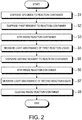
Fig. 2 is a flowchart illustrating an example of a flow of measurement processing performed by a specimen processing apparatus according to the first embodiment; -
Fig. 3 is a perspective view illustrating an example of a specimen storage according to the first embodiment; -
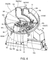
Fig. 4 is a perspective view illustrating an example of the specimen storage according to the first embodiment, in a state where outer-circumferential and inner-circumferential lids are open; -
Fig. 5 is a plan view illustrating the example of the specimen storage according to the first embodiment, in the state where the outer-circumferential and inner-circumferential lids are open; -
Fig. 6 is a perspective view illustrating an example of a part of the specimen storage according to the first embodiment; -
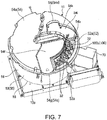
Fig. 7 is a perspective view illustrating an example of the specimen storage according to the first embodiment, in a state where the outer-circumferential lid is open; -
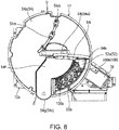
Fig. 8 is a plan view illustrating the example of the specimen storage according to the first embodiment, in the state where the outer-circumferential lid is open; -
Fig. 9 is a perspective view illustrating an example of the specimen storage according to the first embodiment, in a state where the inner-circumferential lid is open; -
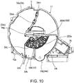
Fig. 10 is a plan view illustrating the example of the specimen storage according to the first embodiment, in the state where the inner-circumferential lid is open; -
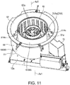
Fig. 11 is a perspective view illustrating an example of the specimen storage according to the first embodiment, in a state where a cover is removed; -
Fig. 12 is a perspective view illustrating an example of an outer-circumferential rotational support of the specimen storage according to the first embodiment, along with containers; -
Fig. 13 is a plan view illustrating an example of the outer-circumferential rotational support of the specimen storage according to the first embodiment, along with the containers; -
Fig. 14 is a perspective view illustrating an example of the outer-circumferential rotational support of the specimen storage according to the first embodiment; -
Fig. 15 is a plan view illustrating the example of the outer-circumferential rotational support of the specimen storage according to the first embodiment; -
Fig. 16 is a perspective view illustrating an example of a rack for the outer-circumferential rotational support according to the first embodiment; -
Fig. 17 is a plan view illustrating the example of the rack for the outer-circumferential rotational support according to the first embodiment; -
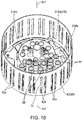
Fig. 18 is a perspective view illustrating an example of an inner-circumferential rotational support of the specimen storage according to the first embodiment, along with containers; -
Fig. 19 is a plan view illustrating an example of the inner-circumferential rotational support of the specimen storage according to the first embodiment, along with the containers; -
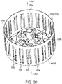
Fig. 20 is a perspective view illustrating an example of the inner-circumferential rotational support of the specimen storage according to the first embodiment; -
Fig. 21 is a plan view illustrating the example of the inner-circumferential rotational support of the specimen storage according to the first embodiment; -
Fig. 22 is a perspective view illustrating an example of a rack for the inner-circumferential rotational support according to the first embodiment; -
Fig. 23 is a plan view illustrating the example of the rack for the inner-circumferential rotational support according to the first embodiment; -
Fig. 24 is a perspective view illustrating an example of the cover according to the first embodiment, in the state where the outer-circumferential and inner-circumferential lids are open; -
Fig. 25 is a perspective view illustrating the example of the cover according to the first embodiment, in the state where the outer-circumferential and inner-circumferential lids are open, seen from a different direction fromFig. 24 ; -
Fig. 26 is a perspective bottom view illustrating the example of the cover according to the first embodiment; and -
Fig. 27 is a perspective bottom view illustrating an example of a cover according to a second embodiment. - Hereinafter, some illustrative embodiments of this disclosure are described. Configurations and controls of the embodiments described below, and operations and effects which are derivable from the configurations and controls are merely an example. This disclosure is implementable also by other than the configurations and controls disclosed in the embodiments described below, and obtainable of various effects with a basic configuration and control thereof. Note that the embodiments illustratively described below include components having similar/same functions to each other. The components having the similar/same functions may be denoted with the same reference characters and description thereof may be omitted.
- As illustrated in
Fig. 1 , a biochemical analyzer 1 includes aspecimen processing apparatus 2 and an information processing apparatus 3. Thespecimen processing apparatus 2 obtains reaction liquid by causing reaction between a specimen (serum, blood plasma, urine etc.) and a reagent, and measures light absorbance of the reaction liquid. The information processing apparatus 3 obtains an amount of component of the specimen, such as cholesterol, based on the measured light absorbance by thespecimen processing apparatus 2. In other words, the biochemical analyzer 1 analyzes the specimen by a colorimetric method. This kind of biochemical analyzer 1 is used, for example, for examination of the specimen for various examination items, such as a cholesterol value. The biochemical analyzer 1 is one example of the analyzer of this disclosure. - The information processing apparatus 3 includes a controller, a memory, a display unit, and a user-interface (neither of them illustrated). The controller has a CPU (Central Processing Unit), a ROM (Read Only Memory), and a RAM (Random Access Memory). The information processing apparatus 3 is communicable with the
specimen processing apparatus 2. The information processing apparatus 3 may be comprised of a personal computer. - The
specimen processing apparatus 2 includes acasing 10, aspecimen storage 11, areagent storage 12, areaction tank 13, aspecimen dispenser 14,reagent dispensers stirrers measurer 19, acleanser 20, and acontroller 21. - The
specimen storage 11 hasrotational supports rotational supports casing 10 to be individually rotatable by adrive device 51A about a rotational axis Ax1 extending in up-and-down directions of thecasing 10. For example, thedrive device 51A includes a rotational source (motor etc.) and a rotation transmission mechanism (gear, belt, pulley etc.). The drive source may be shared between the tworotational supports rotational supports rotational supports specimen containers 32. The plurality ofspecimen containers 32 are set on therotational supports rotational supports specimen containers 32 supported by therotational support 31B are located radially inward of thespecimen containers 32 supported by therotational support 31A with respect to the rotational axis Ax1. Note that,Fig. 1 illustrates some (not all) of the plurality ofspecimen containers 32. - Each
specimen container 32 contains a specimen. Further thespecimen container 32 is applied with a bar code 71 (Fig. 12 ) containing identification information of thespecimen container 32, and thisbar code 71 is read by a bar code reader 70 (Fig. 3 ) provided at a position facing thespecimen container 32 inside thespecimen storage 11. Note that inFig. 12 , thebar code 71 is illustrated only on one of thespecimen containers 32 and omitted onother specimen containers 32. Further thebar code 71 is illustrated schematically. - The
reagent storage 12 hasrotational supports rotational supports casing 10 to be individually rotatable by adrive device 51B about a rotational axis Ax2 extending in the up-and-down directions of thecasing 10. For example, thedrive device 51B includes a rotational source (motor etc.) and a rotation transmission mechanism (gear, belt, pulley etc.). The drive source may be shared between the tworotational supports rotational supports rotational supports reagent containers 34. The plurality ofreagent containers 34 are placed in therotational supports rotational supports reagent containers 34 supported by therotational support 33B are located radially inward of thereagent containers 34 supported by therotational support 33A with respect to the rotational axis Ax2. Note that,Fig. 1 illustrates some (not all) of the plurality ofreagent containers 34. - Each
reagent container 34 contains a reagent. Further thereagent container 34 is applied with a bar code (not illustrated) containing identification information of thereagent container 34, and this bar code is read by a bar code reader (not illustrated) provided at a position facing thereagent container 34 inside thereagent storage 12. - The
reaction tank 13 has a substantially-circular rotor body 35 in a plan view. Therotor body 35 is supported by thecasing 10 to be rotatable by a drive mechanism (not illustrated) about a rotational axis Ax3 extending in the up-and-down directions of thecasing 10. Therotor body 35 is provided with a plurality of light-transparent reaction containers 36. The plurality ofreaction containers 36 are placed around the rotational axis Ax3 in therotor body 35 so as to integrally rotate with therotor body 35. Note that,Fig. 1 illustrates some (not all) of the plurality ofreaction containers 36. Eachreaction container 36 may be structured by a cuvette. The specimen and reagent are dispensed into thereaction container 36, and react with each other within thereaction container 36 to become reaction liquid. Thereaction tank 13 is kept at a temperature suitable for stimulating the reaction between the specimen and the reagent. - The
specimen dispenser 14 has apipette 37 and adrive mechanism 38. Thepipette 37 is rotated by thedrive mechanism 38 about a rotational axis Ax4 extending in the up-and-down directions of thecasing 10, between a position above thespecimen storage 11 and a position above thereaction tank 13. Further thepipette 37 is moved in the up-and-down directions of thecasing 10 by thedrive mechanism 38. Thepipette 37 is connected with a suction-discharge mechanism configured to perform suction and discharge of the specimen. Thespecimen dispenser 14 sucks the specimen inside thespecimen container 32 by thepipette 37 inserted into thespecimen container 32, then inserts thepipette 37 into thereaction container 36, and discharges (dispenses) the specimen into thereaction container 36 from thepipette 37. - The reagent dispensers 15 and 16 have
pipettes mechanisms pipettes drive mechanisms casing 10, respectively, between a position above thereagent storage 12 and a position above thereaction tank 13. Further thepipettes casing 10 by thedrive mechanisms pipettes reagent containers 34 by thepipettes reagent containers 34, then insert thepipettes reaction containers 36, and discharge (dispense) the reagents into thereaction containers 36 from thepipettes - The
measurer 19 includes alight source 45 and a light receiver (not illustrated). Thelight source 45 is located outside thereaction tank 13, and emits light (e.g., halogen light) toward thereaction container 36. The light receiver receives light penetrated thereaction container 36 and measures the intensity of the received light. Themeasurer 19 obtains the light absorbance of the reaction liquid inside thereaction container 36 based on the intensity of light measured by the light receiver. Thelight source 45 is capable of switching a wavelength of light emitted. Thus, themeasurer 19 is capable of measuring light absorbances by using a plurality of kinds of light with different wavelengths. - Each of the
stirrers reaction container 36. Thestirrers reaction containers 36 by rotating the stirring members inserted into thereaction containers 36. - The
cleanser 20 removes (discards) the reaction liquid from thereaction container 36 and cleanses inside thereaction container 36. - The
controller 21 has a CPU, a ROM and a RAM. Thecontroller 21 executes various operations and controls of various parts of thespecimen processing apparatus 2. - The
specimen processing apparatus 2 having the above configuration performs measurement processing. During the measurement processing, thespecimen storage 11, thereagent storage 12, and thereaction tank 13 are moved (to be more specific, rotational members thereof described later in detail rotate) to given positions where they receive the treatments of thespecimen dispenser 14, thereagent dispensing parts stirrers measurer 19, and thecleanser 20. - As illustrated in
Fig. 2 , in the measurement processing, thespecimen dispenser 14 dispenses a given specimen inside thespecimen storage 11 into a givenreaction container 36 of the reaction tank 13 (S1). Thereagent dispenser 15 dispenses a first reagent inside thereagent storage 12 corresponding to a given examination item, into the given reaction container 36 (S2). Thestirrer 17 stirs inside the given reaction container 36 (S3). After a given period of time from the stirring, themeasurer 19 measures the light absorbance of a first reaction liquid obtained from reaction between the given specimen and the first reagent inside the given reaction container 36 (S4). The measured light absorbance is transmitted to the information processing apparatus 3. - Then the
reagent dispenser 16 dispenses a second reagent inside thereagent storage 12 corresponding to the given examination item, into the given reaction container 36 (S5). Thestirrer 18 stirs inside the given reaction container 36 (S6). After a given period of time from the stirring, themeasurer 19 measures the light absorbance of a second reaction liquid obtained from reaction between the first reaction liquid (specimen and first reagent) and the second reagent inside the given reaction container 36 (S7). The measured light absorbance is transmitted to the information processing apparatus 3. Then thecleanser 20 removes the second reaction liquid inside the givenreaction container 36 and cleanses inside the reaction container 36 (S8). Once the two light absorbances are obtained by such measurement processing, the information processing apparatus 3 obtains an amount of component of the specimen (e.g., cholesterol value) based on the light absorbances. Note that the processes of S1 to S8 are repeated for every specimen and examination item. Each of thepipettes - Next, the
specimen storage 11 is described in detail. As illustrated inFig. 3 , thespecimen storage 11 includes ahousing 50. As illustrated inFigs. 4 to 10 , thehousing 50 is formed with anaccommodation space 52 therein, and theaccommodation space 52 accommodates therotational supports specimen containers 32 supported by therotational supports housing 50 is supported by abase component 10a provided to thecasing 10. Thebase component 10a is coupled to an internal surface of a bottom wall (not illustrated) of thecasing 10. Thehousing 50 may be referred to as the container. - As illustrated in
Figs. 3 to 10 , thehousing 50 includes amain body 53 and acover 54. As illustrated inFig. 11 , themain body 53 has a circular-plate-like bottom wall 55 and acylindrical side wall 56 extending upward from an outer circumferential end portion of thebottom wall 55. Themain body 53 is formed with theaccommodation space 52 adjacent to thebottom wall 55 and theside wall 56, and an upper end of themain body 53 is open. - The
cover 54 illustrated inFig. 3 etc. is detachably coupled to the upper end of themain body 53. Thecover 54 covers the top of theaccommodation space 52. By removing thecover 54 from themain body 53, theaccommodation space 52 becomes entirely open (Fig. 11 ). Note that, detailed description of thecover 54 is given below. Thecover 54 is one example of the cover member of this disclosure. - As illustrated in
Figs. 12 to 15 , therotational support 31A has a circular plate part 31Aa centering on the rotational axis Ax1. A plurality of supporting parts 31Ab are provided on an upper surface of the circular plate part 31Aa and arranged circumferentially. For example, each supporting part 31Ab detachably supports arack 100 configured to support two or more of thespecimen containers 32. In other words, the supporting part 31Ab detachably supports thespecimen containers 32 via therack 100. Note that the supporting part 31Ab may directly support thespecimen containers 32. Therotational support 31A rotates about the rotational axis Ax1 with respect to thehousing 50 and therotational support 31B. Therotational support 31A is one example of the first rotational support of this disclosure, and thespecimen container 32 supported by therotational support 31A is one example of the first container of this disclosure. - As illustrated in
Figs. 16 and17 , therack 100 has a plurality of supportingparts 100a configured to support thespecimen containers 32, and ahandle 100b. - As illustrated in
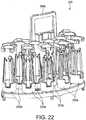
Figs. 18 to 21 , therotational support 31B has a circular plate part 31Ba centering on the rotational axis Ax1. The circular plate part 31Ba is located above the circular plate part 31Aa. The radius of the circular plate part 33Ba is smaller than that of the circular plate part 31Aa. A plurality of supporting parts 31Bb are provided on an upper surface of the circular plate part 31Ba and arranged circumferentially. For example, each supporting part 31Bb detachably supports arack 200 configured to support two or more of thespecimen containers 32. In other words, the supporting part 31Bb detachably supports thespecimen containers 32 via therack 200. Note that the supporting part 31Bb may directly support thespecimen containers 32. Therack 200 and thespecimen containers 32 supported by the supporting part 31Bb are located radially inward of therack 100 and thespecimen containers 32 supported by the supporting part 31Ab. In other words, therotational support 31B supports thespecimen containers 32 at the radially inward side of thespecimen containers 32 supported by therotational support 31A with respect to the rotational axis Ax1. Therotational support 31B rotates about the rotational axis Ax1 with respect to thehousing 50 and therotational support 31A. Therotational support 31B is one example of the second rotational support of this disclosure, and thespecimen container 32 supported by therotational support 31B is one example of the second container of this disclosure. - As illustrated in
Figs. 22 and23 , therack 200 has a plurality of supportingparts 200a configured to support thespecimen containers 32, and ahandle 200b. - Further as illustrated in
Fig. 11 , apartition 60 is provided inside thehousing 50. Thepartition 60 is located between thespecimen containers 32 supported by therotational support 31A and thespecimen containers 32 supported by therotational support 31B (Fig. 4 ). Thepartition 60 extends circumferentially. - The
partition 60 haspartition walls Figs. 12 to 15 , thepartition wall 61 is provided to the circular plate part 31Aa of therotational support 31A. Thepartition wall 61 has a cylindrical shape centering on the rotational axis Ax1. Thepartition wall 61 is located radially inward of thespecimen containers 32 supported by therotational support 31A with respect to the rotational axis Ax1. Further as illustrated inFig. 11 , thepartition wall 61 is formed with a singleopen section 61a (slit). A light emitted from thebar code reader 70 and a reflection light caused by the emitted light reflecting on thebar code 71 which is provided on thespecimen container 32 supported by therotational support 31B (Fig. 12 ) penetrate theopen section 61 a. Note that, theopen section 61a may be covered by a light-transparent member. Moreover, a plurality ofslits 61a may be formed and circumferentially separated from each other. Thepartition wall 61 is one example of the first partition wall of this disclosure. - As illustrated in
Figs. 18 to 21 , thepartition wall 62 is provided to the circular plate part 31Ba of therotational support 31B. Thepartition wall 62 has a cylindrical shape centering on the rotational axis Ax1. Thepartition wall 62 is located radially outward of thespecimen containers 32 supported by therotational support 31B with respect to the rotational axis Ax1. Further thepartition wall 62 is located inward of thepartition wall 61 and separated therefrom. Thepartition wall 62 is formed with a plurality ofopen sections 62a (slits). The plurality ofopen sections 62a are arranged around the rotational axis Ax1 and separated from each other. Theopen section 62a may be provided for everyspecimen container 32 supported by the supporting part 31Bb of therotational support 31B, or provided for given number (plurality) ofspecimen containers 32. A light emitted from thebar code reader 70 and a reflection light caused by the emitted light reflecting on thebar code 71 which is provided on thespecimen container 32 supported by therotational support 31B penetrate theopen section 62a. When one of theopen sections 62a overlaps with theopen section 61 a, reading of thebar code 71 by thebar code reader 70 becomes possible. Note that, eachopen section 62a may be covered by a light-transparent member. Thepartition wall 62 is one example of the second partition wall of this disclosure. - Next the
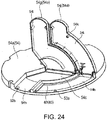
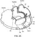
cover 54 is described. As illustrated inFigs. 24 to 26 , thecover 54 is provided with awall part 54a,lids - The
wall part 54a covers thespecimen containers 32 supported by therotational support 31A and thespecimen containers 32 supported by therotational support 31B in one of the directions of the rotational axis Ax1 (from above). - The
wall part 54a is formed withopen sections Figs. 7 and8 , theopen section 54b exposes a partial section (area) 52a of theaccommodation space 52 which is on the radially outward side of thepartition 60 with respect to the rotational axis Ax1 and adjacent to thepartition 60. Theopen section 54b has a size large enough for thespecimen containers 32 which are detachably attached to therotational support 31A (rack 100) to pass through. As illustrated inFigs. 9 and10 , theopen section 54c exposes a partial section (area) 52b of theaccommodation space 52 which is on the radially inward side of thepartition 60 with respect to the rotational axis Ax1 and adjacent to thepartition 60. Theopen section 54c has a size large enough for thespecimen containers 32 which are detachably attached to therotational support 31B (rack 200) to pass through. Theopen section 54b is one example of the first open section of this disclosure, and theopen section 54c is one example of the second open section of this disclosure. - The
lid 54d is provided to (supported by) thewall part 54a so as to be openable. Thelid 54d covers theopen section 54b. Thelid 54d has acover portion 54i which covers thespecimen containers 32 supported by therotational support 31A in a closed state of thelid 54d, and anextension portion 54j extending radially outward from thecover portion 54i with respect to the rotational axis Ax1 in the closed state. Aprotrusion 54k is provided on a lower surface of thecover portion 54i. In the closed state, theprotrusion 54k is inserted into adent 53a formed in an upper end part of themain body 53. Thedent 53a is provided with a detection sensor configured to detect theprotrusion 54k inside thedent 53a. Thelid 54d is one example of the first lid of this disclosure. - The
lid 54e covers theopen section 54c. Thelid 54e has acover portion 54f which covers thespecimen containers 32 supported by therotational support 31B in a closed state of thelid 54e, and anextension portion 54g extending radially outward from thecover portion 54f with respect to the rotational axis Ax1 in the closed state. Theextension portion 54g overlaps with an overlappingportion 54h of thewall part 54a (Fig. 24 ). A protrusion 541 (Fig. 24 ) is provided on a lower surface of thecover portion 54f. In the closed state, theprotrusion 541 is inserted into adent 53b formed in the upper end part of themain body 53. Thedent 53b is provided with a detection sensor configured to detect theprotrusion 541 inside thedent 53b. Thelid 54e is one example of the second lid of this disclosure. - Further as illustrated in
Fig. 26 ,partition walls wall part 54a. Thepartition walls partition 60. Thepartition wall 63 extends toward thepartition wall 61 from a position of thewall part 54a corresponding to theopen section 54b. Thepartition wall 63 has an arc extending circumferentially. In other words, thepartition wall 63 is not annular. Thepartition wall 63 overlaps with thepartition wall 61 in the directions of the rotational axis Ax1 (axial directions). Thepartition wall 64 extends toward thepartition wall 62 from a position of thewall part 54a corresponding to theopen section 54c. Thepartition wall 64 has an arc extending circumferentially. In other words, thepartition wall 64 is not annular. Thepartition wall 64 overlaps with thepartition wall 62 in the directions of the rotational axis Ax1. Thepartition wall 63 is one example of the third partition wall of this disclosure, and thepartition wall 64 is one example of the fourth partition wall of this disclosure. - Further as illustrated in
Fig. 5 , thewall part 54a is formed with a plurality ofopen sections 54m into which thepipette 37 may be inserted. Thepipette 37 is inserted into thereagent container 34 through theopen section 54m. - As described above, in this embodiment, the
partition 60 is located between thespecimen containers 32 supported by therotational support 31A and thespecimen containers 32 supported by therotational support 31B, and extends circumferentially. Thus, when an operator attaches/removes thespecimen containers 32 to/from one ofrotational supports specimen containers 32 supported by the other one of therotational supports - Further in this embodiment, the
cover 54 is provided with thewall part 54a, theopen section 54b exposing thepartial section 52a of theaccommodation space 52 which is on the radially outward side of thepartition 60 with respect to the rotational axis Ax1 and adjacent to thepartition 60 and through which thespecimen containers 32 which are removably attached to therotational support 31A pass, and theopen section 54c exposing thepartial section 52b of theaccommodation space 52 which is on the radially inward side of thepartition 60 with respect to the rotational axis Ax1 and adjacent to thepartition 60 and through which thespecimen containers 32 which are removably attached to therotational support 31B pass. Thus, when the operator attaches/removes thespecimen containers 32 to/from one ofrotational supports specimen containers 32 supported by the other one of therotational supports - Further in this embodiment, the
partition walls partition 60 are provided to therotational supports cover 54 removed, the hand of the operator does not easily touch thespecimen containers 32 supported by the other one of therotational supports - Further in this embodiment, the
partition walls partition 60 extend toward thepartition walls wall part 54a corresponding to theopen sections racks partition walls racks partition walls - Further in this embodiment, the
wall part 54a has the overlappingportion 54h overlapping with theextension portion 54g of thelid 54e. Thus, even when thelid 54e is open, thespecimen containers 32 supported by therotational support 31A are covered by the overlappingportion 54h. - Further in this embodiment, the
partition 60 is formed with theopen sections bar code reader 70 and the reflection light caused by the emitted light reflecting on thebar code 71 which is provided on thespecimen container 32 supported by therotational support 31B penetrate. As a result, thebar code 71 is readable by thebar code reader 70. - Note that, one of the
partition walls - As illustrated in
Fig. 27 , in a second embodiment, thepartition 60 has apartition wall 80 provided to thecover 54. Note that thepartition walls 61 to 64 are not provided in this embodiment. Thepartition wall 80 extends downward from the lower surface of thewall part 54a. Thepartition wall 80 has an arc extending circumferentially. In other words, thepartition wall 80 is not annular. Thepartition wall 80 is located between thespecimen containers 32 supported by therotational support 31A and thespecimen containers 32 supported by therotational support 31B. With this kind of structure, since thepartition wall 80 is not annular, thepartition 60 is easily simplified. - Note that in the embodiments described above, similar to the
specimen storage 11, thereagent storage 12 may have thehousing 50 and thepartition 60. Further theopen sections - Although the embodiments of this disclosure are described above, the embodiments described above are merely some examples. The embodiments may be implemented in other various modes, and various omissions, replacements, combinations and changes may be applied without deviating from the scope of this disclosure. Moreover, the configurations and shapes of the embodiments may partially be replaced with other configurations and shapes. Furthermore, the specifications of each configuration, shape etc. (structure, kind, direction, angle, shape, size, length, width, thickness, height, number, arrangement, position, material etc.) may suitably be changed. For example, in the embodiment described above, the biochemical analyzer 1 is illustratively described as one example of the specimen analyzer; however, it is not limited to this. For example, the analyzer may be an immunoassay analyzer. Further, each partition wall may be made of a light-transparent material. The partition may have a stick-like member and/or a fence-like member. In this case, a plurality of stick-like members and/or a plurality of fence-like members may be arranged circumferentially at a given space interval.
Claims (10)
- An analyzer (1), comprising:a first rotational support (31A, 33A) accommodated in a housing (50) and configured to support a first container (32, 34) and rotate about an rotational axis (Ax1, Ax2) with respect to the housing (50);a second rotational support (31B, 33B) accommodated in the housing (50) and configured to support a second container (32, 34) at a position radially inward of the first container (32, 34) and rotate about the rotational axis (Ax1, Ax2) with respect to the housing (50); anda partition (60) disposed between the first container (32, 34) and the second container (32, 34).
- The analyzer (1) of claim 1, wherein the partition (60) has a first partition wall (61) having a cylindrical shape centering on the rotational axis (Ax1, Ax2) and provided to the first rotational support (31A, 33A).
- The analyzer (1) of claim 1 or 2, wherein the partition (60) has a second partition wall (62) having a cylindrical shape centering on the rotational axis (Ax1, Ax2) and provided to the second rotational support (31B, 33B).
- The analyzer (1) of any one of claims 1 to 3, further comprising a cover member (54) provided to the housing (50),
wherein the housing (50) is formed with an accommodation space (52) accommodating the first and second rotational supports (31A, 33A, 31B, 33B), and
wherein the cover member (54) is provided with:a wall part (54a) covering the first and second containers (32, 34) in one of the directions of the rotational axis (Ax1, Ax2);a first open section (54b) exposing a partial section (52a) of the accommodation space (52) and through which the first container (32, 34) removably attached to the first rotational support (31A, 33A) is inserted, the partial section (52a) located radially outward of the partition (60) and adjacent to the partition (60); anda second open section (54c) exposing a partial section (52b) of the accommodation space (52) and through which the second container (32, 34) removably attached to the second rotational support (31B, 33B) is inserted, the partial section (52b) located radially inward of the partition (60) and adjacent to the partition (60). - The analyzer (1) of claim 2, further comprising a cover member (54) provided to the housing (50),
wherein the housing (50) is formed with an accommodation space (52) accommodating the first and second rotational supports (31A, 33A, 31B, 33B),
wherein the cover member (54) is provided with:a wall part (54a) covering the first and second containers (32, 34) in one of the directions of the rotational axis (Ax1, Ax2);a first open section (54b) exposing a partial section (52a) of the accommodation space (52) and through which the first container (32, 34) removably attached to the first rotational support (31A, 33A) is inserted, the partial section (52a) located radially outward of the partition (60) and adjacent to the partition (60); anda second open section (54c) exposing a partial section (52b) of the accommodation space (52) and through which the second container (32, 34) removably attached to the second rotational support (31B, 33B) is inserted, the partial section (52b) located radially inward of the partition (60) and formed adjacent to the partition (60), andwherein the partition (60) has a third partition wall (63) extending to the first partition wall (61) from a position of the wall part (54a) corresponding to the first open section (54b). - The analyzer (1) of claim 3, further comprising a cover member (54) provided to the housing (50),
wherein the housing (50) is formed with an accommodation space (52) accommodating the first and second rotational supports (31A, 33A, 31B, 33B),
wherein the cover member (54) is provided with:a wall part (54a) covering the first and second containers (32, 34) in one of the directions of the rotational axis (Ax1, Ax2);a first open section (54b) exposing a partial section (52a) of the accommodation space (52) and through which the first container (32, 34) removably attached to the first rotational support (31A, 33A) is inserted, the partial section (52a) located radially outward of the partition (60) and adjacent to the partition (60); anda second open section (54c) exposing a partial section (52b) of the accommodation space (52) and through which the second container (32, 34) removably attached to the second rotational support (31B, 33B) is inserted, the partial section (52b) located radially inward of the partition (60) and formed adjacent to the partition (60), andwherein the partition (60) has a fourth partition wall (64) extending to the second partition wall (62) from a position of the wall part (54a) corresponding to the second open section (54c). - The analyzer (1) of claim 1, further comprising a cover member (54) provided to the housing (50),
wherein the housing (50) is formed with an accommodation space (52) accommodating the first and second rotational supports (31A, 33A, 31B, 33B),
wherein the cover member (54) is provided with:a wall part (54a) covering the first and second containers (32, 34) in one of the directions of the rotational axis (Ax1, Ax2);a first open section (54b) exposing a partial section (52a) of the accommodation space (52) and through which the first container (32, 34) removably attached to the first rotational support (31A, 33A) is inserted, the partial section (52a) located formed radially outward of the partition (60) and adjacent to the partition (60); anda second open section (54c) exposing a partial section (52b) of the accommodation space (52) and through which the second container (32, 34) removably attached to the second rotational support (31B, 33B) is inserted, the partial section (52b) located radially inward of the partition (60) and formed adjacent to the partition (60), andwherein the partition (60) has a partition wall (63, 64) provided to the cover member (54). - The analyzer (1) of any one of claims 1 to 7, wherein the partition (60) is formed with an open section (61a, 62a) through which a light emitted from a bar code reader (70) and a reflection light caused by the emitted light reflecting on a bar code (71) penetrate, the bar code (71) being provided to the second container (32, 34).
- The analyzer (1) of any one of claims 4 to 7, further comprising:a first lid (54d) provided to the wall part (54a) to be openable and configured to cover the first open section (54b); anda second lid (54e) provided to the wall part (54a) to be openable and configured to cover the second open section (54c),wherein the second lid (54e) having a cover portion (54f) that covers the second container (32, 34) in a closed state of the second lid (54e), and an extension portion (54g) extending radially outward from the cover portion (54f) in the closed state,
wherein the wall part (54a) has an overlapping portion (54h) overlapping with the extension portion (54g) in the closed state. - An analyzer (1) substantially as described herein with reference to and as illustrated in the accompanying drawings.
Applications Claiming Priority (1)
| Application Number | Priority Date | Filing Date | Title |
|---|---|---|---|
| JP2015223496A JP6783514B2 (en) | 2015-11-13 | 2015-11-13 | Analysis equipment |
Publications (2)
| Publication Number | Publication Date |
|---|---|
| EP3168623A1 true EP3168623A1 (en) | 2017-05-17 |
| EP3168623B1 EP3168623B1 (en) | 2023-06-14 |
Family
ID=57286395
Family Applications (1)
| Application Number | Title | Priority Date | Filing Date |
|---|---|---|---|
| EP16198467.9A Active EP3168623B1 (en) | 2015-11-13 | 2016-11-11 | Analyzer |
Country Status (3)
| Country | Link |
|---|---|
| EP (1) | EP3168623B1 (en) |
| JP (1) | JP6783514B2 (en) |
| CN (1) | CN107037226B (en) |
Cited By (1)
| Publication number | Priority date | Publication date | Assignee | Title |
|---|---|---|---|---|
| EP4180819A4 (en) * | 2020-07-09 | 2024-07-03 | Hitachi High-Tech Corporation | AUTOMATED ANALYZER |
Families Citing this family (1)
| Publication number | Priority date | Publication date | Assignee | Title |
|---|---|---|---|---|
| JP7470362B2 (en) * | 2020-01-29 | 2024-04-18 | 株式会社テクノメデイカ | Urine collection cup management device |
Citations (5)
| Publication number | Priority date | Publication date | Assignee | Title |
|---|---|---|---|---|
| US4276258A (en) * | 1980-01-28 | 1981-06-30 | Coulter Electronics, Inc. | Sample and stat feeding system and sample tray |
| US5827479A (en) * | 1996-01-19 | 1998-10-27 | Hitachi, Ltd. | Apparatus for analyzing a plurality of analysis items |
| JP3051618B2 (en) * | 1993-10-25 | 2000-06-12 | 富士写真フイルム株式会社 | Dry analytical film supply device |
| US20090004057A1 (en) * | 2007-06-29 | 2009-01-01 | Naoto Sato | Automatic analyzer and reagent storage thereof |
| JP2013120160A (en) | 2011-12-08 | 2013-06-17 | Hitachi High-Technologies Corp | Automatic analyzing apparatus |
Family Cites Families (9)
| Publication number | Priority date | Publication date | Assignee | Title |
|---|---|---|---|---|
| JPS607232B2 (en) * | 1976-06-18 | 1985-02-22 | 中外製薬株式会社 | Reaction sample tube automatic transfer analyzer |
| JPH0321868A (en) * | 1989-06-20 | 1991-01-30 | Fuji Photo Film Co Ltd | Storage device for liquid to be inspected |
| US5510082A (en) * | 1993-01-25 | 1996-04-23 | Fuji Photo Film Co., Ltd. | Chemical analysis film supplier |
| JP3274325B2 (en) * | 1995-09-04 | 2002-04-15 | 株式会社東芝 | Material storage |
| JP4851266B2 (en) * | 2006-06-30 | 2012-01-11 | シスメックス株式会社 | Sample analyzer |
| JP2009139269A (en) * | 2007-12-07 | 2009-06-25 | Hitachi High-Technologies Corp | Automatic analyzer |
| JP2010237021A (en) * | 2009-03-31 | 2010-10-21 | Sysmex Corp | Analyzer |
| CN102221604B (en) * | 2010-04-14 | 2014-05-07 | 深圳迈瑞生物医疗电子股份有限公司 | Sample tray of biochemical analyzer |
| JP6012728B2 (en) * | 2012-06-25 | 2016-10-25 | 協和メデックス株式会社 | Cassette and reagent set |
-
2015
- 2015-11-13 JP JP2015223496A patent/JP6783514B2/en active Active
-
2016
- 2016-11-11 CN CN201610995530.3A patent/CN107037226B/en active Active
- 2016-11-11 EP EP16198467.9A patent/EP3168623B1/en active Active
Patent Citations (5)
| Publication number | Priority date | Publication date | Assignee | Title |
|---|---|---|---|---|
| US4276258A (en) * | 1980-01-28 | 1981-06-30 | Coulter Electronics, Inc. | Sample and stat feeding system and sample tray |
| JP3051618B2 (en) * | 1993-10-25 | 2000-06-12 | 富士写真フイルム株式会社 | Dry analytical film supply device |
| US5827479A (en) * | 1996-01-19 | 1998-10-27 | Hitachi, Ltd. | Apparatus for analyzing a plurality of analysis items |
| US20090004057A1 (en) * | 2007-06-29 | 2009-01-01 | Naoto Sato | Automatic analyzer and reagent storage thereof |
| JP2013120160A (en) | 2011-12-08 | 2013-06-17 | Hitachi High-Technologies Corp | Automatic analyzing apparatus |
Cited By (1)
| Publication number | Priority date | Publication date | Assignee | Title |
|---|---|---|---|---|
| EP4180819A4 (en) * | 2020-07-09 | 2024-07-03 | Hitachi High-Tech Corporation | AUTOMATED ANALYZER |
Also Published As
| Publication number | Publication date |
|---|---|
| EP3168623B1 (en) | 2023-06-14 |
| JP2017090354A (en) | 2017-05-25 |
| CN107037226A (en) | 2017-08-11 |
| CN107037226B (en) | 2022-01-11 |
| JP6783514B2 (en) | 2020-11-11 |
Similar Documents
| Publication | Publication Date | Title |
|---|---|---|
| EP1837654B1 (en) | Blood analyzer | |
| JP6178333B2 (en) | Reagent container and automatic analyzer | |
| JP6343139B2 (en) | Reagent station for automatic analyzer | |
| EP2128627B1 (en) | Analyzer for performing medical diagnostic analysis | |
| JP7195359B2 (en) | automatic analyzer | |
| JP2005537127A (en) | Method and apparatus for mixing liquid samples using sinusoidal mixing | |
| EP3168623B1 (en) | Analyzer | |
| EP0576291A2 (en) | Automated clinical analyzer with temperature control | |
| JP6900268B2 (en) | Automatic analyzer | |
| WO2011001647A1 (en) | Automatic analysis device and measurement method | |
| EP3168621B1 (en) | Analyzer | |
| JP6680515B2 (en) | Analysis equipment | |
| JP5025409B2 (en) | Automatic analyzer | |
| JP7847642B2 (en) | automatic analyzer | |
| EP3168622B1 (en) | Analyzer | |
| JP4871152B2 (en) | Automatic analyzer | |
| CN107037225B (en) | Container storage rack and analysis device | |
| JP7502043B2 (en) | Reagent storage and automatic analyzer | |
| JP7142155B2 (en) | automatic analyzer | |
| JP2019100894A (en) | Automatic analysis device and automatic analysis method | |
| JP2024055414A (en) | Reagent storage system, automatic analysis system, and suppression member | |
| JP5706252B2 (en) | Automatic analyzer |
Legal Events
| Date | Code | Title | Description |
|---|---|---|---|
| PUAI | Public reference made under article 153(3) epc to a published international application that has entered the european phase |
Free format text: ORIGINAL CODE: 0009012 |
|
| STAA | Information on the status of an ep patent application or granted ep patent |
Free format text: STATUS: THE APPLICATION HAS BEEN PUBLISHED |
|
| AK | Designated contracting states |
Kind code of ref document: A1 Designated state(s): AL AT BE BG CH CY CZ DE DK EE ES FI FR GB GR HR HU IE IS IT LI LT LU LV MC MK MT NL NO PL PT RO RS SE SI SK SM TR |
|
| AX | Request for extension of the european patent |
Extension state: BA ME |
|
| STAA | Information on the status of an ep patent application or granted ep patent |
Free format text: STATUS: REQUEST FOR EXAMINATION WAS MADE |
|
| 17P | Request for examination filed |
Effective date: 20171116 |
|
| RBV | Designated contracting states (corrected) |
Designated state(s): AL AT BE BG CH CY CZ DE DK EE ES FI FR GB GR HR HU IE IS IT LI LT LU LV MC MK MT NL NO PL PT RO RS SE SI SK SM TR |
|
| STAA | Information on the status of an ep patent application or granted ep patent |
Free format text: STATUS: EXAMINATION IS IN PROGRESS |
|
| 17Q | First examination report despatched |
Effective date: 20200408 |
|
| GRAP | Despatch of communication of intention to grant a patent |
Free format text: ORIGINAL CODE: EPIDOSNIGR1 |
|
| STAA | Information on the status of an ep patent application or granted ep patent |
Free format text: STATUS: GRANT OF PATENT IS INTENDED |
|
| INTG | Intention to grant announced |
Effective date: 20230207 |
|
| GRAS | Grant fee paid |
Free format text: ORIGINAL CODE: EPIDOSNIGR3 |
|
| GRAA | (expected) grant |
Free format text: ORIGINAL CODE: 0009210 |
|
| STAA | Information on the status of an ep patent application or granted ep patent |
Free format text: STATUS: THE PATENT HAS BEEN GRANTED |
|
| AK | Designated contracting states |
Kind code of ref document: B1 Designated state(s): AL AT BE BG CH CY CZ DE DK EE ES FI FR GB GR HR HU IE IS IT LI LT LU LV MC MK MT NL NO PL PT RO RS SE SI SK SM TR |
|
| REG | Reference to a national code |
Ref country code: CH Ref legal event code: EP |
|
| REG | Reference to a national code |
Ref country code: DE Ref legal event code: R096 Ref document number: 602016080311 Country of ref document: DE |
|
| REG | Reference to a national code |
Ref country code: AT Ref legal event code: REF Ref document number: 1579595 Country of ref document: AT Kind code of ref document: T Effective date: 20230715 |
|
| REG | Reference to a national code |
Ref country code: LT Ref legal event code: MG9D |
|
| REG | Reference to a national code |
Ref country code: NL Ref legal event code: MP Effective date: 20230614 |
|
| PG25 | Lapsed in a contracting state [announced via postgrant information from national office to epo] |
Ref country code: SE Free format text: LAPSE BECAUSE OF FAILURE TO SUBMIT A TRANSLATION OF THE DESCRIPTION OR TO PAY THE FEE WITHIN THE PRESCRIBED TIME-LIMIT Effective date: 20230614 Ref country code: NO Free format text: LAPSE BECAUSE OF FAILURE TO SUBMIT A TRANSLATION OF THE DESCRIPTION OR TO PAY THE FEE WITHIN THE PRESCRIBED TIME-LIMIT Effective date: 20230914 Ref country code: ES Free format text: LAPSE BECAUSE OF FAILURE TO SUBMIT A TRANSLATION OF THE DESCRIPTION OR TO PAY THE FEE WITHIN THE PRESCRIBED TIME-LIMIT Effective date: 20230614 |
|
| REG | Reference to a national code |
Ref country code: AT Ref legal event code: MK05 Ref document number: 1579595 Country of ref document: AT Kind code of ref document: T Effective date: 20230614 |
|
| PG25 | Lapsed in a contracting state [announced via postgrant information from national office to epo] |
Ref country code: RS Free format text: LAPSE BECAUSE OF FAILURE TO SUBMIT A TRANSLATION OF THE DESCRIPTION OR TO PAY THE FEE WITHIN THE PRESCRIBED TIME-LIMIT Effective date: 20230614 Ref country code: NL Free format text: LAPSE BECAUSE OF FAILURE TO SUBMIT A TRANSLATION OF THE DESCRIPTION OR TO PAY THE FEE WITHIN THE PRESCRIBED TIME-LIMIT Effective date: 20230614 Ref country code: LV Free format text: LAPSE BECAUSE OF FAILURE TO SUBMIT A TRANSLATION OF THE DESCRIPTION OR TO PAY THE FEE WITHIN THE PRESCRIBED TIME-LIMIT Effective date: 20230614 Ref country code: LT Free format text: LAPSE BECAUSE OF FAILURE TO SUBMIT A TRANSLATION OF THE DESCRIPTION OR TO PAY THE FEE WITHIN THE PRESCRIBED TIME-LIMIT Effective date: 20230614 Ref country code: HR Free format text: LAPSE BECAUSE OF FAILURE TO SUBMIT A TRANSLATION OF THE DESCRIPTION OR TO PAY THE FEE WITHIN THE PRESCRIBED TIME-LIMIT Effective date: 20230614 Ref country code: GR Free format text: LAPSE BECAUSE OF FAILURE TO SUBMIT A TRANSLATION OF THE DESCRIPTION OR TO PAY THE FEE WITHIN THE PRESCRIBED TIME-LIMIT Effective date: 20230915 |
|
| PG25 | Lapsed in a contracting state [announced via postgrant information from national office to epo] |
Ref country code: FI Free format text: LAPSE BECAUSE OF FAILURE TO SUBMIT A TRANSLATION OF THE DESCRIPTION OR TO PAY THE FEE WITHIN THE PRESCRIBED TIME-LIMIT Effective date: 20230614 |
|
| PG25 | Lapsed in a contracting state [announced via postgrant information from national office to epo] |
Ref country code: SK Free format text: LAPSE BECAUSE OF FAILURE TO SUBMIT A TRANSLATION OF THE DESCRIPTION OR TO PAY THE FEE WITHIN THE PRESCRIBED TIME-LIMIT Effective date: 20230614 |
|
| PG25 | Lapsed in a contracting state [announced via postgrant information from national office to epo] |
Ref country code: IS Free format text: LAPSE BECAUSE OF FAILURE TO SUBMIT A TRANSLATION OF THE DESCRIPTION OR TO PAY THE FEE WITHIN THE PRESCRIBED TIME-LIMIT Effective date: 20231014 |
|
| PG25 | Lapsed in a contracting state [announced via postgrant information from national office to epo] |
Ref country code: SM Free format text: LAPSE BECAUSE OF FAILURE TO SUBMIT A TRANSLATION OF THE DESCRIPTION OR TO PAY THE FEE WITHIN THE PRESCRIBED TIME-LIMIT Effective date: 20230614 Ref country code: SK Free format text: LAPSE BECAUSE OF FAILURE TO SUBMIT A TRANSLATION OF THE DESCRIPTION OR TO PAY THE FEE WITHIN THE PRESCRIBED TIME-LIMIT Effective date: 20230614 Ref country code: RO Free format text: LAPSE BECAUSE OF FAILURE TO SUBMIT A TRANSLATION OF THE DESCRIPTION OR TO PAY THE FEE WITHIN THE PRESCRIBED TIME-LIMIT Effective date: 20230614 Ref country code: PT Free format text: LAPSE BECAUSE OF FAILURE TO SUBMIT A TRANSLATION OF THE DESCRIPTION OR TO PAY THE FEE WITHIN THE PRESCRIBED TIME-LIMIT Effective date: 20231016 Ref country code: IS Free format text: LAPSE BECAUSE OF FAILURE TO SUBMIT A TRANSLATION OF THE DESCRIPTION OR TO PAY THE FEE WITHIN THE PRESCRIBED TIME-LIMIT Effective date: 20231014 Ref country code: EE Free format text: LAPSE BECAUSE OF FAILURE TO SUBMIT A TRANSLATION OF THE DESCRIPTION OR TO PAY THE FEE WITHIN THE PRESCRIBED TIME-LIMIT Effective date: 20230614 Ref country code: CZ Free format text: LAPSE BECAUSE OF FAILURE TO SUBMIT A TRANSLATION OF THE DESCRIPTION OR TO PAY THE FEE WITHIN THE PRESCRIBED TIME-LIMIT Effective date: 20230614 Ref country code: AT Free format text: LAPSE BECAUSE OF FAILURE TO SUBMIT A TRANSLATION OF THE DESCRIPTION OR TO PAY THE FEE WITHIN THE PRESCRIBED TIME-LIMIT Effective date: 20230614 |
|
| PG25 | Lapsed in a contracting state [announced via postgrant information from national office to epo] |
Ref country code: PL Free format text: LAPSE BECAUSE OF FAILURE TO SUBMIT A TRANSLATION OF THE DESCRIPTION OR TO PAY THE FEE WITHIN THE PRESCRIBED TIME-LIMIT Effective date: 20230614 |
|
| REG | Reference to a national code |
Ref country code: DE Ref legal event code: R097 Ref document number: 602016080311 Country of ref document: DE |
|
| PLBE | No opposition filed within time limit |
Free format text: ORIGINAL CODE: 0009261 |
|
| STAA | Information on the status of an ep patent application or granted ep patent |
Free format text: STATUS: NO OPPOSITION FILED WITHIN TIME LIMIT |
|
| PG25 | Lapsed in a contracting state [announced via postgrant information from national office to epo] |
Ref country code: DK Free format text: LAPSE BECAUSE OF FAILURE TO SUBMIT A TRANSLATION OF THE DESCRIPTION OR TO PAY THE FEE WITHIN THE PRESCRIBED TIME-LIMIT Effective date: 20230614 |
|
| PG25 | Lapsed in a contracting state [announced via postgrant information from national office to epo] |
Ref country code: SI Free format text: LAPSE BECAUSE OF FAILURE TO SUBMIT A TRANSLATION OF THE DESCRIPTION OR TO PAY THE FEE WITHIN THE PRESCRIBED TIME-LIMIT Effective date: 20230614 |
|
| 26N | No opposition filed |
Effective date: 20240315 |
|
| PG25 | Lapsed in a contracting state [announced via postgrant information from national office to epo] |
Ref country code: SI Free format text: LAPSE BECAUSE OF FAILURE TO SUBMIT A TRANSLATION OF THE DESCRIPTION OR TO PAY THE FEE WITHIN THE PRESCRIBED TIME-LIMIT Effective date: 20230614 Ref country code: IT Free format text: LAPSE BECAUSE OF FAILURE TO SUBMIT A TRANSLATION OF THE DESCRIPTION OR TO PAY THE FEE WITHIN THE PRESCRIBED TIME-LIMIT Effective date: 20230614 |
|
| REG | Reference to a national code |
Ref country code: CH Ref legal event code: PL |
|
| PG25 | Lapsed in a contracting state [announced via postgrant information from national office to epo] |
Ref country code: MC Free format text: LAPSE BECAUSE OF FAILURE TO SUBMIT A TRANSLATION OF THE DESCRIPTION OR TO PAY THE FEE WITHIN THE PRESCRIBED TIME-LIMIT Effective date: 20230614 |
|
| PG25 | Lapsed in a contracting state [announced via postgrant information from national office to epo] |
Ref country code: LU Free format text: LAPSE BECAUSE OF NON-PAYMENT OF DUE FEES Effective date: 20231111 |
|
| PG25 | Lapsed in a contracting state [announced via postgrant information from national office to epo] |
Ref country code: CH Free format text: LAPSE BECAUSE OF NON-PAYMENT OF DUE FEES Effective date: 20231130 |
|
| GBPC | Gb: european patent ceased through non-payment of renewal fee |
Effective date: 20231111 |
|
| PG25 | Lapsed in a contracting state [announced via postgrant information from national office to epo] |
Ref country code: MC Free format text: LAPSE BECAUSE OF FAILURE TO SUBMIT A TRANSLATION OF THE DESCRIPTION OR TO PAY THE FEE WITHIN THE PRESCRIBED TIME-LIMIT Effective date: 20230614 Ref country code: LU Free format text: LAPSE BECAUSE OF NON-PAYMENT OF DUE FEES Effective date: 20231111 Ref country code: CH Free format text: LAPSE BECAUSE OF NON-PAYMENT OF DUE FEES Effective date: 20231130 |
|
| REG | Reference to a national code |
Ref country code: BE Ref legal event code: MM Effective date: 20231130 |
|
| REG | Reference to a national code |
Ref country code: IE Ref legal event code: MM4A |
|
| PG25 | Lapsed in a contracting state [announced via postgrant information from national office to epo] |
Ref country code: IE Free format text: LAPSE BECAUSE OF NON-PAYMENT OF DUE FEES Effective date: 20231111 |
|
| PG25 | Lapsed in a contracting state [announced via postgrant information from national office to epo] |
Ref country code: GB Free format text: LAPSE BECAUSE OF NON-PAYMENT OF DUE FEES Effective date: 20231111 |
|
| PG25 | Lapsed in a contracting state [announced via postgrant information from national office to epo] |
Ref country code: BE Free format text: LAPSE BECAUSE OF NON-PAYMENT OF DUE FEES Effective date: 20231130 |
|
| PG25 | Lapsed in a contracting state [announced via postgrant information from national office to epo] |
Ref country code: FR Free format text: LAPSE BECAUSE OF NON-PAYMENT OF DUE FEES Effective date: 20231130 |
|
| PG25 | Lapsed in a contracting state [announced via postgrant information from national office to epo] |
Ref country code: IE Free format text: LAPSE BECAUSE OF NON-PAYMENT OF DUE FEES Effective date: 20231111 Ref country code: GB Free format text: LAPSE BECAUSE OF NON-PAYMENT OF DUE FEES Effective date: 20231111 Ref country code: FR Free format text: LAPSE BECAUSE OF NON-PAYMENT OF DUE FEES Effective date: 20231130 Ref country code: BE Free format text: LAPSE BECAUSE OF NON-PAYMENT OF DUE FEES Effective date: 20231130 |
|
| PG25 | Lapsed in a contracting state [announced via postgrant information from national office to epo] |
Ref country code: BG Free format text: LAPSE BECAUSE OF FAILURE TO SUBMIT A TRANSLATION OF THE DESCRIPTION OR TO PAY THE FEE WITHIN THE PRESCRIBED TIME-LIMIT Effective date: 20230614 |
|
| PG25 | Lapsed in a contracting state [announced via postgrant information from national office to epo] |
Ref country code: BG Free format text: LAPSE BECAUSE OF FAILURE TO SUBMIT A TRANSLATION OF THE DESCRIPTION OR TO PAY THE FEE WITHIN THE PRESCRIBED TIME-LIMIT Effective date: 20230614 |
|
| PG25 | Lapsed in a contracting state [announced via postgrant information from national office to epo] |
Ref country code: CY Free format text: LAPSE BECAUSE OF FAILURE TO SUBMIT A TRANSLATION OF THE DESCRIPTION OR TO PAY THE FEE WITHIN THE PRESCRIBED TIME-LIMIT; INVALID AB INITIO Effective date: 20161111 |
|
| PG25 | Lapsed in a contracting state [announced via postgrant information from national office to epo] |
Ref country code: HU Free format text: LAPSE BECAUSE OF FAILURE TO SUBMIT A TRANSLATION OF THE DESCRIPTION OR TO PAY THE FEE WITHIN THE PRESCRIBED TIME-LIMIT; INVALID AB INITIO Effective date: 20161111 |
|
| PG25 | Lapsed in a contracting state [announced via postgrant information from national office to epo] |
Ref country code: TR Free format text: LAPSE BECAUSE OF FAILURE TO SUBMIT A TRANSLATION OF THE DESCRIPTION OR TO PAY THE FEE WITHIN THE PRESCRIBED TIME-LIMIT Effective date: 20230614 |
|
| PGFP | Annual fee paid to national office [announced via postgrant information from national office to epo] |
Ref country code: DE Payment date: 20250930 Year of fee payment: 10 |