EP3168580A1 - Hornantenne - Google Patents
Hornantenne Download PDFInfo
- Publication number
- EP3168580A1 EP3168580A1 EP15194471.7A EP15194471A EP3168580A1 EP 3168580 A1 EP3168580 A1 EP 3168580A1 EP 15194471 A EP15194471 A EP 15194471A EP 3168580 A1 EP3168580 A1 EP 3168580A1
- Authority
- EP
- European Patent Office
- Prior art keywords
- antenna
- horn
- horn antenna
- filling
- collar
- Prior art date
- Legal status (The legal status is an assumption and is not a legal conclusion. Google has not performed a legal analysis and makes no representation as to the accuracy of the status listed.)
- Granted
Links
Images


Classifications
-
- G—PHYSICS
- G01—MEASURING; TESTING
- G01F—MEASURING VOLUME, VOLUME FLOW, MASS FLOW OR LIQUID LEVEL; METERING BY VOLUME
- G01F23/00—Indicating or measuring liquid level or level of fluent solid material, e.g. indicating in terms of volume or indicating by means of an alarm
- G01F23/22—Indicating or measuring liquid level or level of fluent solid material, e.g. indicating in terms of volume or indicating by means of an alarm by measuring physical variables, other than linear dimensions, pressure or weight, dependent on the level to be measured, e.g. by difference of heat transfer of steam or water
- G01F23/28—Indicating or measuring liquid level or level of fluent solid material, e.g. indicating in terms of volume or indicating by means of an alarm by measuring physical variables, other than linear dimensions, pressure or weight, dependent on the level to be measured, e.g. by difference of heat transfer of steam or water by measuring the variations of parameters of electromagnetic or acoustic waves applied directly to the liquid or fluent solid material
- G01F23/284—Electromagnetic waves
-
- G—PHYSICS
- G01—MEASURING; TESTING
- G01S—RADIO DIRECTION-FINDING; RADIO NAVIGATION; DETERMINING DISTANCE OR VELOCITY BY USE OF RADIO WAVES; LOCATING OR PRESENCE-DETECTING BY USE OF THE REFLECTION OR RERADIATION OF RADIO WAVES; ANALOGOUS ARRANGEMENTS USING OTHER WAVES
- G01S13/00—Systems using the reflection or reradiation of radio waves, e.g. radar systems; Analogous systems using reflection or reradiation of waves whose nature or wavelength is irrelevant or unspecified
- G01S13/88—Radar or analogous systems specially adapted for specific applications
-
- G—PHYSICS
- G01—MEASURING; TESTING
- G01S—RADIO DIRECTION-FINDING; RADIO NAVIGATION; DETERMINING DISTANCE OR VELOCITY BY USE OF RADIO WAVES; LOCATING OR PRESENCE-DETECTING BY USE OF THE REFLECTION OR RERADIATION OF RADIO WAVES; ANALOGOUS ARRANGEMENTS USING OTHER WAVES
- G01S7/00—Details of systems according to groups G01S13/00, G01S15/00, G01S17/00
- G01S7/02—Details of systems according to groups G01S13/00, G01S15/00, G01S17/00 of systems according to group G01S13/00
- G01S7/03—Details of HF subsystems specially adapted therefor, e.g. common to transmitter and receiver
-
- H—ELECTRICITY
- H01—ELECTRIC ELEMENTS
- H01Q—ANTENNAS, i.e. RADIO AERIALS
- H01Q1/00—Details of, or arrangements associated with, antennas
- H01Q1/12—Supports; Mounting means
- H01Q1/22—Supports; Mounting means by structural association with other equipment or articles
- H01Q1/225—Supports; Mounting means by structural association with other equipment or articles used in level-measurement devices, e.g. for level gauge measurement
-
- H—ELECTRICITY
- H01—ELECTRIC ELEMENTS
- H01Q—ANTENNAS, i.e. RADIO AERIALS
- H01Q13/00—Waveguide horns or mouths; Slot antennas; Leaky-waveguide antennas; Equivalent structures causing radiation along the transmission path of a guided wave
- H01Q13/02—Waveguide horns
-
- H—ELECTRICITY
- H01—ELECTRIC ELEMENTS
- H01Q—ANTENNAS, i.e. RADIO AERIALS
- H01Q19/00—Combinations of primary active antenna elements and units with secondary devices, e.g. with quasi-optical devices, for giving the antenna a desired directional characteristic
- H01Q19/06—Combinations of primary active antenna elements and units with secondary devices, e.g. with quasi-optical devices, for giving the antenna a desired directional characteristic using refracting or diffracting devices, e.g. lens
- H01Q19/08—Combinations of primary active antenna elements and units with secondary devices, e.g. with quasi-optical devices, for giving the antenna a desired directional characteristic using refracting or diffracting devices, e.g. lens for modifying the radiation pattern of a radiating horn in which it is located
-
- G—PHYSICS
- G01—MEASURING; TESTING
- G01S—RADIO DIRECTION-FINDING; RADIO NAVIGATION; DETERMINING DISTANCE OR VELOCITY BY USE OF RADIO WAVES; LOCATING OR PRESENCE-DETECTING BY USE OF THE REFLECTION OR RERADIATION OF RADIO WAVES; ANALOGOUS ARRANGEMENTS USING OTHER WAVES
- G01S7/00—Details of systems according to groups G01S13/00, G01S15/00, G01S17/00
- G01S7/02—Details of systems according to groups G01S13/00, G01S15/00, G01S17/00 of systems according to group G01S13/00
- G01S7/027—Constructional details of housings, e.g. form, type, material or ruggedness
Definitions
- the present invention relates to a horn antenna for a radar measuring device, in particular a radar fill level measuring device according to the preamble of patent claim 1.
- Radar measuring devices for example radar level measuring devices are known from the prior art, which detect a level of a filling material in a container, in particular of liquids and bulk solids according to the transit time principle.
- Such radar level measuring devices are equipped with horn antennas, for example, via which an injected RF signal is radiated in the direction of the filling material and reflected by it.
- the microwave pulses reflected from the product are detected and determined by measuring the duration of these pulses, a distance from the level gauge to the contents.
- Horn antennas basically have a simple and robust construction, a very good efficiency and are inexpensive to manufacture. However, as soon as an inside of the antenna horn is contaminated, this has a negative effect on the performance of the horn antenna.
- the cover of the horn antenna with a radome can keep dirt and aggressive media out of the antenna horn, such horn antennas are still not suitable for use in overpressure or underpressure environments.
- a horn antenna for a radar measuring device in particular a radar level gauge with the features of patent claim 1 and a radar level measuring device with such a horn antenna according to claim 15.
- a horn antenna according to the invention for a radar measuring device in particular a radar level gauge with an antenna horn radiating in the front direction, a rear side Feed device and a filling that at least partially fills the antenna horn and closes the front side is characterized in that the filling has at least a first portion of a first material, which closes a cavity of the antenna horn in a Schoabstrahlraum front side, and a second portion of a second Material which is disposed within the closed cavity.
- the horn antenna with a filling comprising at least two sections can be achieved that the first portion, the antenna horn front side, d. H. in the main emission direction, can be optimally adapted to the ambient conditions acting on the antenna from the outside, while the at least one second section does not have to fulfill these boundary conditions.
- the first material is optimized in terms of its thermal, mechanical and / or chemical properties.
- the mechanical properties may also include a thermal expansion coefficient, which may be adapted to the material of the horn antenna, for example.
- the antenna horn and the first section used for covering and optionally also sealing can thermally expand and contract to the same extent, so that the desired covering and / or sealing effect is not endangered by thermal influences.
- a low coefficient of thermal expansion of the first material also has the advantage that for sealing between the first portion and the collar, smaller diameter sealing members, such as smaller gauge O-rings, may be used, resulting in improved high frequency characteristics of the assembly.
- An optimal combination is achieved if the second material is optimized with regard to its dielectric properties, in particular with regard to attenuation in the high-frequency range, in particular at frequencies above 5 GHz. In this way, a combination of materials can be achieved, which has both mechanically and / or chemically and dielectrically very good properties.
- the first section may have a free surface with a convex shape and thus be configured, for example, as a dielectric lens for beam shaping of the horn antenna.
- a convex shape comprises in particular lenticular or cone-shaped surfaces which represent particularly simple geometries which are also easy to clean.
- the antenna horn on the front side may additionally have a circumferential support edge extending essentially perpendicular to the main emission direction. Furthermore, a collar extending substantially in the main emission direction can be arranged on the support edge, wherein the antenna horn, the support edge and the collar are preferably formed in one piece.
- the first portion of the filling is supported on the support edge and thus a having increased pressure capacity in the axial direction.
- the first section may extend, for example, starting from the support edge in the main emission direction and be supported on the back side thereof.
- the filling fills the antenna horn in the radial direction, d. H. perpendicular to the main emission direction, completely off.
- the first section can completely fill a space bounded by the collar in the radial direction, and advantageously at least one circumferential seal, for example an O-ring, can be arranged between the first section and the collar.
- an expansion of the filling in the radial direction is selected such that thermally induced expansion of the filling is possible.
- the formation of higher propagation modes is counteracted by an air gap between the filling and the inside of the antenna horn, which is technically advantageous in terms of HF.
- first section and the second section adjoin one another directly and have an interface which extends substantially perpendicular to the main emission direction and which, for example, has a stepped, convex, conical or lenticular shape.
- a step-shaped configuration may, in particular, have a plurality of steps of different heights, so that, for example, an approach to a lenticular design can be achieved.
- a step-shaped design of the interface ensures that the free surface of the first section has a greater curvature or, in the case of a conical design of the free surface, a smaller angle at the tip, resulting in an improved dripping behavior when the antenna is dewy with liquids. In this way, a defocussing and a reduction of the reflection attenuation otherwise caused by the condensation and a resulting stronger antenna ringing, which leads to overall performance losses of the antenna, are reduced.
- first portion and the second portion may be non-positively connected to each other, for example, the interface may have an internal or external thread or an undercut, so that the first portion and the second portion before connection to the horn antenna, d. H. especially before being inserted into the antenna horn can already be firmly connected to each other.
- the first material and the second material and a course of the interface are coordinated such that the free Surface of the first section has an improved dripping behavior.
- Poyletheretherketon PEEK
- PTFE polytetrafluoroethylene
- a radar level gauge a horn antenna with an antenna horn radiating in the front direction, a rear feed and a filling at least partially fills the antenna horn and closes the front side, wherein the filling has at least a first portion of a first material, the one Cavity of the antenna horn in a Schoabstrahlraum front ends, and has a second portion of a second material which is disposed within the closed cavity.
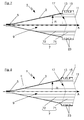
- FIG. 1 shows a first embodiment of a horn antenna 1 according to the present application.
- the horn antenna 1 has a substantially funnel-shaped antenna horn 3, on the back of a feed device 5 is arranged on.
- the feeding device 5 may be, for example, a waveguide connected to the antenna horn 3 or a surface radiator arranged at the end of the antenna horn 3, for example a so-called patch element.
- On the antenna horn 3 is in the front-side direction, ie at one in the main radiation A the feed device 5 opposite end, in the radial direction R, that is substantially perpendicular to the main emission A extending, circumferential support edge 13 is formed, which is after a radially extending section as a running in the main emission direction A, circumferential collar 15 continues.
- the antenna horn 3, the circumferential support edge 13 and the collar 15 are integrally formed from a metallic material.
- the horn antenna 1 is filled with a filling 7, which in the present embodiment consists of a first portion 71 and a second portion 72.
- the first section 71 terminates the horn antenna 1 in the main emission direction A on the front side and is supported on the rear side by the circumferential support edge 13.
- the first portion 71 is formed so that it approximately completely fills a circumferentially bounded by the collar 15 space in the radial direction R, wherein between the first portion 71 and the circumferential collar 15 is provided a circumferential seal.
- the first section 71 has two grooves extending in the circumferential direction, in which sealing elements 23, which in the present case are designed as O-rings, are arranged. The sealing elements 23 thus seal off the first section 71 toward the collar 15, so that an ambient medium can not penetrate into the interior of the horn antenna 1.
- the first section 71 is formed in the present embodiment with a front in the main emission direction A free surface 11 with a convex surface shape.
- the free surface 11 on a lenticular configuration.
- a second section 72 of the filling 7 is arranged from a different material.
- the first section 71 is in the present embodiment of Poyletheretherketon (PEEK) a high performance plastic with high mechanical, thermal and chemical stability educated.
- PEEK Poyletheretherketon
- the present horn antenna can be used in overpressure and underpressure environments with chemically aggressive media and high temperature variations.
- first section materials for the first section are, for example, ceramic polyvinylidene fluoride (PVDF) or polyphenylene sulfide (PPS) in question. Also suitable are other high-performance plastics and fiber-reinforced plastics that can absorb particularly high mechanical loads.
- PVDF ceramic polyvinylidene fluoride
- PPS polyphenylene sulfide
- other high-performance plastics and fiber-reinforced plastics that can absorb particularly high mechanical loads.
- the second section 72 of a second material is formed directly in the present exemplary embodiment.
- PTFE polytetrafluoroethylene
- the second portion may be made of polytetrafluoroethylene (PTFE), polypropylene (PP), or polyethylene (PE) or other plastics having suitable high frequency properties.
- PTFE polytetrafluoroethylene
- PP polypropylene
- PE polyethylene
- the interface 17 between the first portion 71 and the second portion 72 is formed so that the second portion 72 has a extending in the main emission direction A extension with an external thread 19 applied thereto and the first portion has a corresponding recess with an internal thread.
- the first portion 71 and the second portion 72 of the filling 7 can thus be non-positively and positively connected with each other and thus already pre-assembled outside the horn antenna 1.
- the second section 72 fills the cavity 9 of the antenna horn completely and extends to an approach of the feed device 5 arranged on the horn antenna 1 waveguide.
- FIG. 3 a third embodiment of a horn antenna 1 according to the present application is shown.
- the embodiment according to FIG. 3 differs from the two previous embodiments only in the configuration of the interface 17 between the first portion 71 and the second portion 72 of the filling 7.
- the interface 17 is in the in FIG. 3 embodiment shown stepped, whereby a reinforcement of the curvature of the free surface 11 of the first portion 71 is achieved.
- the horn antenna 1 thus has an improved dripping behavior when dewing with liquids, which causes a significant reduction of caused by the dewing defocusing of the antenna and reduction of the reflection attenuation and a resulting antenna ringing. Overall, a significant improvement in the performance of the antenna can be achieved in this way.
- a horn antenna 1 is shown as an alternative embodiment having a conically shaped interface 17 between the first portion 71 and the second portion 72.
- Such a configuration also provides a self-centering arrangement, wherein the reflection caused by the different dielectric constants of the individual materials reflections are not directly reflected back to the electronics of the receiver by the oblique to the main emission direction A interface 19, but arrive greatly attenuated by the oblique reflection in the receiver. This results in a reduced ringing of the antenna.
- FIG. 5 a fifth embodiment of a horn antenna 1 is shown, wherein both the free surface 11 and the interface 17 is designed lens-shaped.
- a variant is shown in which the curvature of the second filling 72 performs a partial focusing and thereby enhances the curvature of the first filling 71.
- the curvature of the second filling 72 is adjusted so that it takes over the rest of the focusing.
- the advantages here are a very precise focusing and thus a maximum gain, lower side lobes of the horn antenna 1 and the increased curvature an improved dripping behavior.
- FIG. 6 shows a sixth embodiment of a horn antenna 1, wherein the free surface 11 lens-shaped and the interface 17 is designed step-shaped.
- the interface 17 has in the in FIG. 6 illustrated embodiment, a contour with a step which projects beyond the support rim 13 in the main emission direction A, is provided with a thread 19.
- the first portion 71 and the second portion 72 of the filling 7 can thus form over the thread 19 and positively connected with each other and aligned with each other.
- FIG. 7 a seventh embodiment of a horn antenna 1 is shown, wherein both the free surface 11 and the interface 17 is configured conical.
- the FIG. 7 illustrated embodiment is particularly optimized in terms of their dripping behavior on the free surface 11. Due to the conical configuration of the free surface 11, a defined point is here defined for a drop of any condensate precipitating on the free surface 11, whereby a reduction of the angle at the apex is achieved by the conical configuration of the interface 17, so that the condensate This point also has a better flow behavior.
- FIG. 8 an eighth embodiment of a horn antenna 1 is shown, wherein the free surface 11 and the interface 17 as in the embodiment in FIG. 7 both are cone-shaped.
- the embodiment of FIG. 8 is different from that of FIG. 7 in that the peripheral support edge 13 in the embodiment of the FIG. 8 is formed step-shaped, so that the second portion 72 of the filling 7 with a front side formed on the second filling 72 and web-like outwardly extending support web rests on a first radial portion of the support rim 13.
- the first portion 71 of the filling 7 rests on a second radial portion of the support rim 13, which adjoins the first radial portion after an axially extending step portion.
- the support web of the second portion 72 is thus clamped between the first radial portion of the support rim 13 and the first portion 71 of the filling 7 and thereby fixed in the axial direction.
- FIG. 9 shown illustration is also clearly seen that on the collar 15 in the main emission direction A front side in the radial direction R jumping inwardly nose 16 is integrally formed.
- the filling 7 consisting of the first portion 71 and the second portion 72 is thus fixed in the antenna horn 3 and can be attached in a simple manner, for example via a snap connection, alternatively via a bayonet connection or the like, in the antenna horn 3.
- the nose 16 can be designed either as a circumferential web or distributed over the circumference, preferably arranged at regular intervals individual lugs.
- the lugs 16 may be integrally formed with the collar 15 or connected to this releasably or permanently.
- a circumferential snap ring could be attached to the front of the collar 15 and the filling thus fixed in the antenna horn 7.
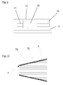
- FIG. 9 shows the in FIG. 8 marked with I section.
- FIG. 10 is the in FIG. 8 II shown enlarged section, which is particularly clearly seen in this illustration that between the antenna horn 3 and the filling 7, in this case the second portion 72 of the filling 7, an air gap 4 remains.
- This air gap is advantageous from a high-frequency technical point of view and also makes it possible for thermally induced expansions of the filling 7 in the radial direction to be possible.
- a particularly simple embodiment for achieving this air gap 4 is shown, in which provided by externally to the second portion 72 of the filling 7 projections 73 a defined distance between the filling 7 and the antenna horn 3 is set. This Anformung also ensures that the filling 72 is always centered in the antenna horn 3 is mounted.
- an O-ring or the like could be provided between the antenna horn 3 and the filling 7 for adjusting the distance.
Landscapes
- Physics & Mathematics (AREA)
- Engineering & Computer Science (AREA)
- Radar, Positioning & Navigation (AREA)
- Remote Sensing (AREA)
- General Physics & Mathematics (AREA)
- Electromagnetism (AREA)
- Computer Networks & Wireless Communication (AREA)
- Thermal Sciences (AREA)
- Fluid Mechanics (AREA)
- Waveguide Aerials (AREA)
- Details Of Aerials (AREA)
- Aerials With Secondary Devices (AREA)
Abstract
Description
- Die vorliegende Erfindung betrifft eine Hornantenne für ein Radarmessgerät, insbesondere ein Radar-Füllstandmessgerät gemäß dem Oberbegriff des Patentanspruchs 1.
- Aus dem Stand der Technik sind Radarmessgeräte, beispielsweise Radar-Füllstandmessgeräte bekannt, die nach dem Laufzeitprinzip einen Füllstand eines in einem Behälter befindlichen Füllguts, insbesondere von Flüssigkeiten und Schüttgütern detektieren. Solche Radar-Füllstandmessgeräte sind beispielsweise mit Hornantennen ausgestattet, über die ein eingekoppeltes HF-Signal in Richtung des Füllgutes abgestrahlt und von diesem reflektiert wird. In einem kombinierten Sende- und Empfangssystem des Radar-Füllstandmessgerätes werden die vom Füllgut reflektierten Mikrowellenimpulse erfasst und durch Messung der Laufzeit dieser Pulse ein Abstand von dem Füllstandmessgerät zu dem Füllgut ermittelt.
- Hornantennen haben grundsätzlich einen einfachen und robusten Aufbau, einen sehr guten Wirkungsgrad und sind kostengünstig herzustellen. Sobald allerdings eine Innenseite des Antennenhorns verschmutzt wird, wirkt sich dies negativ auf die Leistungsfähigkeit der Hornantenne aus.
- Aus dem Stand der Technik ist es daher bekannt, die Antennen solcher Füllstandmessgeräte gegen Verschmutzung und/oder Korrosion aufgrund einer aggressiven Messumgebung zu schützen. Dies wird beispielsweise dadurch erreicht, dass die Antennen mit einem Radom vorderseitig abgedeckt oder das Horn mit einem Medium, z. B. Kunststoff gefüllt ist.
- Die Abdeckung der Hornantenne mit einem Radom kann zwar Verschmutzungen und aggressive Medien aus dem Antennenhorn fernhalten, solche Hornantennen sind aber nach wie vor nicht zum Einsatz in Über- oder Unterdruckumgebungen geeignet.
- Im Stand der Technik existieren daher auch Hornantennen, bei denen das Antennenhorn vollständig mit einem festen Medium, z. B. Kunststoff gefüllt ist. Bei diesen gefüllten Hornantennen wird es jedoch als nachteilig empfunden, dass die zur Füllung verwendeten Kunststoffe häufig unzureichende dielektrische Eigenschaften aufweisen und zudem nicht ausreichend geeignet sind, aggressiven Messumgebungen hinreichend zu widerstehen oder in hygienekritischen Anwendungen, bei denen Reinigungsvorgänge mit hohen Temperaturen vorgesehen sind, eingesetzt zu werden.
- Es ist die Aufgabe der vorliegenden Erfindung eine Hornantenne für ein Radarmessgerät, insbesondere ein Radar-FüllstandMessgerät, derart weiterzubilden, dass sie die aus dem Stand der Technik bekannten Nachteile nicht mehr aufweist.
- Diese Aufgabe wird gelöst durch eine Hornantenne für ein Radarmessgerät, insbesondere ein Radar-Füllstandmessgerät mit den Merkmalen des Patentanspruchs 1 sowie ein Radar-FüllstandMessgerät mit einer solchen Hornantenne gemäß Patentanspruch 15.
- Vorteilhafte Weiterbildungen sind Gegenstand abhängiger Patentansprüche.
- Eine erfindungsgemäße Hornantenne für ein Radarmessgerät, insbesondere ein Radar-Füllstandmessgerät mit einem in vorderseitiger Richtung strahlenden Antennenhorn, einer rückseitigen Speiseeinrichtung und einer Füllung, die das Antennenhorn wenigstens teilweise ausfüllt und vorderseitig verschließt zeichnet sich dadurch aus, dass die Füllung wenigstens einen ersten Abschnitt aus einem ersten Material aufweist, der einen Hohlraum des Antennenhorns in einer Hauptabstrahlrichtung vorderseitig abschließt, und einen zweiten Abschnitt aus einem zweiten Material aufweist, der innerhalb des abgeschlossenen Hohlraums angeordnet ist.
- Durch eine derartige Ausgestaltung der Hornantenne mit einer wenigstens zwei Abschnitte umfassenden Füllung kann erreicht werden, dass der erste Abschnitt, der das Antennenhorn vorderseitig, d. h. in Hauptabstrahlrichtung, verschließt optimal auf die von außen auf die Antenne einwirkenden Umgebungsbedingungen angepasst sein kann, während der wenigstens eine zweite Abschnitt diese Randbedingungen nicht erfüllen muss.
- Vorteilhafterweise ist das erste Material hinsichtlich seiner thermischen, mechanischen und/oder chemischen Eigenschaften optimiert. Auf diese Weise wird erreicht, dass beispielsweise eine hohe Über- und/oder Unterdruckfähigkeit, thermisch optimierte Eigenschaften und/oder eine erhöhte chemische Widerstandsfähigkeit gegen aggressive Medien zur Verfügung steht. Ferner können die mechanischen Eigenschaften auch einen thermischen Ausdehnungskoeffizienten, der beispielsweise an das Material der Hornantenne angepasst sein kann, mit umfassen. Auf diese Weise kann erreicht werden, dass sich das Antennenhorn und der erste zur Abdeckung und gegebenenfalls auch Abdichtung verwendete Abschnitt in gleichem Maße thermisch ausdehnen und zusammenziehen kann, so dass die angestrebte Abdeckungs- und/oder Dichtwirkung durch thermische Einflüsse nicht gefährdet wird.
- Ein geringer thermischer Ausdehnungskoeffizient des ersten Materials hat außerdem den Vorteil, dass für eine Abdichtung zwischen dem ersten Abschnitt und dem Kragen dadurch Dichtelemente geringerer Abmessung, beispielsweise O-Ringe mit einer kleineren Schnurstärke verwendet werden können, was zu verbesserten Hochfrequenzeigenschaften der Anordnung führt.
- Eine optimale Kombination wird erreicht, wenn das zweite Material hinsichtlich seiner dielektrischen Eigenschaften insbesondere im Hinblick auf eine Dämpfung im Hochfrequenzbereich, insbesondere bei Frequenzen über 5 GHz optimiert ist. Auf diese Weise kann eine Materialkombination erreicht werden, die sowohl mechanisch und/oder chemisch als auch dielektrisch sehr gute Eigenschaften besitzt.
- Der erste Abschnitt kann dabei in Hauptabstrahlrichtung eine freie Fläche mit konvexer Formgebung aufweisen und damit beispielsweise als dielektrische Linse zur Strahlformung der Hornantenne ausgebildet sein. Eine konvexe Formgebung umfasst dabei insbesondere linsenförmig oder kegelförmig ausgestaltete Oberflächen, die besonders einfache Geometrien, die auch einfach zu reinigen sind, darstellen.
- Zur Erhöhung einer mechanischen Stabilität kann das Antennenhorn vorderseitig zusätzlich einen umlaufenden, sich im Wesentlichen senkrecht zur Hauptabstrahlrichtung erstreckenden Auflagerand aufweisen. An dem Auflagerand kann ferner ein sich im Wesentlichen in Hauptabstrahlrichtung erstreckender Kragen angeordnet sein, wobei das Antennenhorn, der Auflagerand und der Kragen bevorzugt einstückig ausgebildet sind. Hinsichtlich einer Über- und/oder Unterdruckstabilität der vorliegenden Hornantenne kann es vorteilhaft sein, wenn sich der erste Abschnitt der Füllung an dem Auflagerand abstützt und damit eine erhöhte Druckaufnahmefähigkeit in Axialrichtung aufweist. Der erste Abschnitt kann sich dabei beispielsweise ausgehend von dem Auflagerand in Hauptabstrahlrichtung erstrecken und rückseitig an selbigem abgestützt sein.
- Vorteilhafterweise füllt die Füllung das Antennenhorn in Radialrichtung, d. h. senkrecht zur Hauptabstrahlrichtung, vollständig aus. Insbesondere kann dabei der erste Abschnitt einen durch den Kragen in Radialrichtung begrenzten Raum vollständig ausfüllen und vorteilhafterweise wenigstens eine umlaufende Dichtung, beispielsweise ein O-Ring, zwischen dem ersten Abschnitt und dem Kragen angeordnet sein. Innerhalb des Antennenhorns ist eine Ausdehnung der Füllung in Radialrichtung so gewählt, dass thermisch induzierte Ausdehnungen der Füllung möglich sind. Ferner wird durch einen Luftspalt zwischen der Füllung und der Innenseite des Antennenhorns der Entstehung höherer Ausbreitungsmoden entgegengewirkt, was HF-technisch vorteilhaft ist.
- In einer bevorzugten Ausgestaltungsform grenzen der erste Abschnitt und der zweite Abschnitt unmittelbar aneinander und weisen eine sich im Wesentlichen senkrecht zur Hauptabstrahlrichtung erstreckende Grenzfläche auf, die beispielsweise stufenförmig, konvex, kegelförmig oder linsenförmig ausgebildet ist. Eine stufenförmige Ausgestaltung kann insbesondere eine Mehrzahl von Stufen unterschiedlicher Höhen aufweisen, sodass beispielsweise eine Annäherung an eine linsenförmige Ausgestaltung erreicht werden kann.
- Durch eine konvexe Ausgestaltung der Grenzfläche wird eine selbstzentrierende Anordnung geschaffen, die beispielsweise durch das Vorsehen einer Stufe eine besonders exakte Ausrichtung der beiden Abschnitte zueinander erlaubt.
- Durch eine stufenförmige Ausgestaltung der Grenzfläche wird erreicht, dass die freie Fläche des ersten Abschnitts eine größere Krümmung oder im Falle einer kegelförmigen Ausgestaltung der freien Fläche einen geringeren Winkel an der Spitze aufweist, wodurch sich ein verbessertes Abtropfverhalten bei Betauung der Antenne mit Flüssigkeiten ergibt. Auf diese Weise wird eine durch die Betauung ansonsten verursachte Defokussierung und Reduzierung der Reflexionsdämpfung und ein hieraus resultierendes stärkeres Antennenklingeln, was insgesamt zu Leistungseinbußen der Antenne führt, reduziert.
- Durch eine geschickte Auswahl der für die Füllung verwendeten Kunststoffe und eine entsprechende Ausgestaltung der Grenzfläche kann die Wölbung der freien Oberfläche verstärkt und damit das Abtropfverhalten verbessert werden. Sobald die zweite Füllung in die erste Füllung hineinragt, tritt dieser positive Effekt auf. Besonders einfache Ausgestaltungen sind z. B. eine stufenförmige, kegelförmige oder linsenförmige Ausgestaltung der zweiten Füllung sowie eine daran angepasste Kontur der ersten Füllung.
- Ferner können der erste Abschnitt und der zweite Abschnitt kraftschlüssig miteinander verbunden sein, beispielsweise kann die Grenzfläche ein innenliegendes oder auch außenliegendes Gewinde oder einen Hinterschnitt aufweisen, so dass der erste Abschnitt und der zweite Abschnitt vor einer Verbindung mit der Hornantenne, d. h. insbesondere vor einem Einsetzen in das Antennenhorn bereits fest miteinander verbunden sein können.
- In einer besonders bevorzugten Ausgestaltungsform sind das erste Material und das zweite Material sowie ein Verlauf der Grenzfläche derart aufeinander abgestimmt, dass die freie Oberfläche des ersten Abschnitts ein verbessertes Abtropfverhalten aufweist.
- Eine hinsichtlich Fokussierung und Abtropfverhalten optimierte Ausgestaltung wird erreicht, wenn sowohl die Grenzfläche als auch die freie Oberfläche kegelförmig ausgestaltet sind. Als Material kann hierbei vorteilhafterweise Poyletheretherketon (PEEK) als erste Füllung und Polytetrafluorethylen (PTFE) als zweite Füllung eingesetzt werden.
- Erfindungsgemäß ist außerdem ein Radar-Füllstandmessgerät, einer Hornantenne mit einem in vorderseitige Richtung strahlenden Antennenhorn, einer rückseitigen Speiseeinrichtung und einer Füllung, die das Antennenhorn wenigstens teilweise ausfüllt und vorderseitig verschließt, wobei die Füllung wenigstens einen ersten Abschnitt aus einem ersten Material aufweist, der einen Hohlraum des Antennenhorns in einer Hauptabstrahlrichtung vorderseitig abschließt, und einen zweiten Abschnitt aus einem zweiten Material aufweist, der innerhalb des abgeschlossenen Hohlraums angeordnet ist.
- Die vorliegende Erfindung wird nachfolgend anhand von Ausführungsbeispielen unter Bezugnahme auf die beigefügten Figuren eingehend erläutert.
- Es zeigen:
- Figur 1
- ein erstes Ausführungsbeispiel einer Hornantenne,
- Figur 2
- ein zweites Ausführungsbeispiel einer Hornantenne,
- Figur 3
- ein drittes Ausführungsbeispiel einer Hornantenne,
- Figur 4
- ein viertes Ausführungsbeispiel einer Hornantenne
- Figur 5
- ein fünftes Ausführungsbeispiel einer Hornantenne,
- Figur 6
- ein sechstes Ausführungsbeispiel einer Hornantenne,
- Figur 7
- ein siebtes Ausführungsbeispiel einer Hornantenne,
- Figur 8
- ein achtes Ausführungsbeispiel einer Hornantenne,
- Figur 9
- eine Ausschnittsvergrößerung aus
Figur 8 und - Figur 10
- eine zweite Ausschnittsvergrößerung aus
Figur 8 . -
Figur 1 zeigt ein erstes Ausführungsbeispiel einer Hornantenne 1 gemäß der vorliegenden Anmeldung. Die Hornantenne 1 weist ein im Wesentlichen trichterförmig ausgebildetes Antennenhorn 3, an dem rückseitig eine Speiseeinrichtung 5 angeordnet ist, auf. Die Speiseeinrichtung 5 kann beispielsweise ein mit dem Antennenhorn 3 verbundener Hohlleiter oder ein am Ende des Antennenhorns 3 angeordneter Flächenstrahler, beispielsweise ein sogenanntes Patchelement sein. An dem Antennenhorn 3 ist in vorderseitiger Richtung, d. h. an einer in Hauptabstrahlrichtung A dem der Speiseeinrichtung 5 gegenüberliegenden Ende, ein sich in Radialrichtung R, d. h. im Wesentlichen senkrecht zur Hauptabstrahlrichtung A erstreckender, umlaufender Auflagerand 13 angeformt, der sich nach einem radial verlaufenden Abschnitt als ein in Hauptabstrahlrichtung A verlaufender, umlaufenden Kragen 15 fortsetzt. Im vorliegenden Ausführungsbeispiel sind das Antennenhorn 3, der umlaufende Auflagerand 13 sowie der Kragen 15 einstückig aus einem metallischen Werkstoff ausgebildet. - Die Hornantenne 1 ist mit einer Füllung 7, die im vorliegenden Ausführungsbeispiel aus einem ersten Abschnitt 71 und einem zweiten Abschnitt 72 besteht, ausgefüllt. Der erste Abschnitt 71 schließt die Hornantenne 1 in Hauptabstrahlrichtung A vorderseitig ab und stützt sich rückseitig an dem umlaufenden Auflagerand 13 ab. Der erste Abschnitt 71 ist dabei so ausgebildet, dass er einen umlaufend durch den Kragen 15 begrenzten Raum in Radialrichtung R annähernd vollständig ausfüllt, wobei zwischen dem ersten Abschnitt 71 und dem umlaufenden Kragen 15 eine umlaufende Abdichtung vorgesehen ist. Der erste Abschnitt 71 weist dafür im vorliegenden Ausführungsbeispiel zwei in Umfangsrichtung verlaufende Nuten auf, in denen Dichtelemente 23, die vorliegend als O-Ringe ausgebildet sind, angeordnet sind. Die Dichtelemente 23 dichten damit den ersten Abschnitt 71 zu dem Kragen 15 hin ab, so dass ein Umgebungsmedium nicht in den Innenraum der Hornantenne 1 eindringen kann.
- Der erste Abschnitt 71 ist im vorliegenden Ausführungsbeispiel mit einer in Hauptabstrahlrichtung A vorne liegenden freien Fläche 11 mit konvexer Oberflächenform ausgebildet. Bei dem in
Figur 1 dargestellten Ausführungsbeispiel weist die freie Fläche 11 eine linsenförmige Ausgestaltung auf. Es sind sphärische und asphärische Ausgestaltungen, beispielsweise mit parabelförmigem Verlauf oder kegelförmige Ausgestaltungen der freien Fläche 11 denkbar. - Rückseitig des ersten Abschnitts 71 ist im vorliegenden Ausführungsbeispiel ein zweiter Abschnitt 72 der Füllung 7 aus einem anderen Material angeordnet.
- Der erste Abschnitt 71 ist im vorliegenden Ausführungsbeispiel aus Poyletheretherketon (PEEK) einem Hochleistungskunststoff mit hoher mechanischer, thermischer und chemischer Stabilität ausgebildet. Auf diese Weise kann die vorliegende Hornantenne in Über- und Unterdruck beaufschlagten Umgebungen mit chemisch aggressiven Medien und hohen Temperaturschwankungen eingesetzt werden.
- Als weitere Materialien für den ersten Abschnitt kommen beispielsweise Keramik- Polyvinylideenfluorid (PVDF) oder Polyphenylensulfid (PPS) in Frage. In Frage kommen ferner weitere Hochleistungskunststoffe sowie faserverstärkte Kunststoffe, die besonders hohe mechanische Belastungen aufnehmen können.
- Rückseitig zu dem ersten Abschnitt 71 ist im vorliegenden Ausführungsbeispiel unmittelbar der zweite Abschnitt 72 aus einem zweiten Material, vorliegend Polytetrafluorethylen (PTFE) ausgebildet. PTFE hat im Vergleich zu PEEK deutliche bessere HF-Eigenschaften und kann daher vorteilhaft in einem Hohlraum 9 des Antennenhorns 3 eingesetzt werden.
- Der zweite Abschnitt kann beispielsweise aus Polytetrafluorethylen (PTFE), Polypropylen (PP) oder Polyethylen (PE) oder anderen Kunststoffen mit geeigneten Hochfrequenzeigenschaften gefertigt sein.
- Im vorliegenden Ausführungsbeispiel ist die Grenzfläche 17 zwischen dem ersten Abschnitt 71 und dem zweiten Abschnitt 72 so ausgebildet, dass der zweite Abschnitt 72 einen sich in Hauptabstrahlrichtung A erstreckenden Fortsatz mit einem darauf aufgebrachten Außengewinde 19 und der erste Abschnitt eine entsprechende Ausnehmung mit einem Innengewinde aufweist. Der erste Abschnitt 71 und der zweite Abschnitt 72 der Füllung 7 können somit kraftschlüssig und formschlüssig miteinander verbunden und damit bereits außerhalb der Hornantenne 1 vormontiert werden. Der zweite Abschnitt 72 füllt den Hohlraum 9 des Antennenhorns vollständig aus und reicht bis zu einem Ansatz des als Speiseeinrichtung 5 an der Hornantenne 1 angeordneten Hohlleiters.
-
Figur 2 zeigt ein zweites Ausführungsbeispiel einer Hornantenne 1 gemäß der vorliegenden Anmeldung. In dem Ausführungsbeispiel gemäßFigur 2 sind der erste Abschnitt 71 und der zweite Abschnitt 72 durch eine über einen Hinterschnitt 21 in dem ersten Abschnitt und eine korrespondierend dazu an dem zweiten Abschnitt 72 ausgebildete Anformung gebildete Schnappgeometrie miteinander verbunden. Durch eine derartige Ausgestaltung kann in einfacher Weise eine kraft- und formschlüssige Verbindung zwischen dem ersten Abschnitt 71 und dem zweiten Abschnitt 72 sowie eine selbstzentrierende Anordnung der beiden Abschnitte 71, 72 zueinander erreicht werden. - In
Figur 3 ist ein drittes Ausführungsbeispiel einer Hornantenne 1 gemäß der vorliegenden Anmeldung dargestellt. Das Ausführungsbeispiel gemäßFigur 3 unterscheidet sich von den beiden vorhergehenden Ausführungsbeispielen lediglich in der Ausgestaltung der Grenzfläche 17 zwischen dem ersten Abschnitt 71 und dem zweiten Abschnitt 72 der Füllung 7. Die Grenzfläche 17 ist in dem inFigur 3 gezeigten Ausführungsbeispiel stufenförmig ausgebildet, wodurch eine Verstärkung der Wölbung der freien Fläche 11 des ersten Abschnitts 71 erreicht wird. Die Hornantenne 1 weist damit ein verbessertes Abtropfverhalten bei Betauung mit Flüssigkeiten auf, was eine deutliche Reduktion einer durch die Betauung hervorgerufenen Defokussierung der Antenne und Reduzierung der Reflexionsdämpfung und einem daraus resultierenden Antennenklingeln bewirkt. Insgesamt kann auf diese Weise eine deutliche Verbesserung der Leistung der Antenne erreicht werden. - In
Figur 4 ist in einem vierten Ausführungsbeispiel eine Hornantenne 1 eine alternative Ausgestaltungsform mit einer kegelförmig ausgestalteten Grenzfläche 17 zwischen dem ersten Abschnitt 71 und dem zweiten Abschnitt 72 gezeigt. Eine derartige Ausgestaltung bietet ebenfalls eine selbstzentrierende Anordnung, wobei durch die schräg zur Hauptabstrahlrichtung A stehende Grenzfläche 19 die durch die unterschiedlichen Dielektrizitätskonstanten der einzelnen Materialien entstehenden Reflexionen nicht direkt zur Elektronik des Empfängers zurückreflektiert werden, sondern durch die schräge Reflexion im Empfänger stark abgeschwächt ankommen. Daraus resultiert ein verringertes Klingeln der Antenne. - In
Figur 5 ist ein fünftes Ausführungsbeispiel einer Hornantenne 1 gezeigt, wobei sowohl die freie Fläche 11 als auch die Grenzfläche 17 linsenförmig ausgestaltet ist. InFigur 5 wird eine Variante gezeigt, bei der die Wölbung der zweiten Füllung 72 eine Teilfokussierung vornimmt und die Wölbung der ersten Füllung 71 dabei verstärkt. Die Wölbung der zweiten Füllung 72 ist so abgestimmt, dass diese den Rest der Fokussierung übernimmt. Die Vorteile sind hier eine sehr genaue Fokussierung und somit ein maximaler Gewinn, geringere Nebenkeulen der Hornantenne 1 sowie durch die verstärkte Wölbung ein verbessertes Abtropfverhalten. -
Figur 6 zeigt ein sechstes Ausführungsbeispiel einer Hornantenne 1, wobei die freie Fläche 11 linsenförmig und die Grenzfläche 17 stufenförmig ausgestaltet ist. Die Grenzfläche 17 weist in dem inFigur 6 dargestellten Ausführungsbeispiel eine Kontur mit einer Stufe auf, die in Hauptabstrahlrichtung A über den Auflagerand 13 hinausragt, mit einem Gewinde 19 versehen ist. Der erste Abschnitt 71 und der zweite Abschnitt 72 der Füllung 7 können damit über das Gewinde 19 form- und kraftschlüssig miteinander verbunden und zueinander ausgerichtet werden. - In
Figur 7 ist ein siebtes Ausführungsbeispiel einer Hornantenne 1 gezeigt, wobei sowohl die freie Fläche 11 als auch die Grenzfläche 17 kegelförmig ausgestaltet ist. Die inFigur 7 dargestellte Ausführungsform ist besonders hinsichtlich ihres Abtropfverhaltens an der freien Fläche 11 optimiert. Durch die kegelförmige Ausgestaltung der freien Fläche 11 wird hier ein definierter Punkt für ein Abtropfen etwaig sich an der freien Oberfläche 11 niederschlagenden Kondensats definiert, wobei durch die kegelförmige Ausgestaltung der Grenzfläche 17 eine Verkleinerung des Winkels an der Kegelspitze erreicht wird, so dass das Kondensat zu diesem Punkt auch ein besseres Ablaufverhalten aufweist. - In
Figur 8 ist ein achtes Ausführungsbeispiel einer Hornantenne 1 gezeigt, wobei die freie Fläche 11 und die Grenzfläche 17 wie bei dem Ausführungsbeispiel inFigur 7 beide kegelförmig ausgestaltet sind. Das Ausführungsbeispiel derFigur 8 unterscheidet sich von dem derFigur 7 dadurch, dass der umlaufende Auflagerand 13 im Ausführungsbeispiel derFigur 8 stufenförmig ausgebildet ist, so dass der zweite Abschnitt 72 der Füllung 7 mit einem vorderseitig an der zweiten Füllung 72 angeformten und sich stegförmig nach außen erstreckenden Auflagesteg auf einem ersten radialen Abschnitt des Auflagerands 13 aufliegt. Der erste Abschnitt 71 der Füllung 7 liegt auf einem zweiten radialen Abschnitt des Auflagerands 13 auf, der sich an den ersten radialen Abschnitt nach einem in Axialrichtung verlaufenden Stufenabschnitt anschließt. Der Auflagesteg des zweiten Abschnitts 72 ist damit zwischen den ersten radialen Abschnitt des Auflagerands 13 und dem ersten Abschnitt 71 der Füllung 7 eingeklemmt und dadurch in Axialrichtung fixiert. - Es ist eine Ausschnittsvergrößerung des in Hauptabstrahlrichtung A vorne liegenden Abschnitts der Hornantenne 1 im Bereich des Kragens 15 gezeigt. Diese vergrößerte Darstellung ist besonders deutlich zu erkennen, dass die als O-Ringe ausgestalteten Dichtelemente 23 in einer Nut des ersten Abschnitts 71 liegen und eine Abdichtung zu dem Kragen 15 hin gewährleisten. Es sei an dieser Stelle angemerkt, dass eine solche Abdichtung nicht zwingend notwendig ist und abhängig von einem vorherrschenden Druck beim Einsatz der Hornantenne 1 sowie der Art der auf die Hornantenne 1 einwirkenden Medien abhängig gemacht werden kann.
- In der in
Figur 9 gezeigten Darstellung ist außerdem deutlich ersichtlich, dass an dem Kragen 15 in Hauptabstrahlrichtung A vorderseitig eine in Radialrichtung R nach innen springende Nase 16 einstückig angeformt ist. Durch die Nase 16 wird eine Klemmwirkung auf den ersten Abschnitt 71 der Füllung 7 ausgeübt und dieser an einer Bewegung aus dem Antennenhorn 3 heraus gehindert. Die Füllung 7 bestehend aus dem ersten Abschnitt 71 und dem zweiten Abschnitt 72 ist damit in dem Antennenhorn 3 fixiert und kann auf einfache Weise, beispielsweise über eine Schnappverbindung, alternativ über eine Bajonettverbindung oder dergleichen, in dem Antennenhorn 3 befestigt sein. - Es sei an dieser Stelle angemerkt, dass die Nase 16 entweder als umlaufender Steg oder als über den Umfang verteilte, bevorzugt in regelmäßigen Abständen angeordnete einzelne Nasen ausgebildet sein kann. Die Nasen 16 können einstückig mit dem Kragen 15 ausgebildet oder mit diesem lösbar oder unlösbar verbunden sein. Beispielsweise könnte ein umlaufender Schnappring vorderseitig auf den Kragen 15 aufgesteckt und die Füllung damit in dem Antennenhorn 7 fixiert werden.
-
Figur 9 zeigt den inFigur 8 mit I gekennzeichneten Abschnitt. - In
Figur 10 ist der inFigur 8 mit II gekennzeichnete Ausschnitt vergrößert dargestellt, wobei in dieser Darstellung besonders deutlich zu erkennen ist, dass zwischen dem Antennenhorn 3 und der Füllung 7, vorliegend dem zweiten Abschnitt 72 der Füllung 7 ein Luftspalt 4 verbleibt. Dieser Luftspalt ist aus hochfrequenztechnischer Sicht vorteilhaft und ermöglicht außerdem, dass thermisch induzierte Ausdehnungen der Füllung 7 in Radialrichtung möglich sind. InFigur 10 ist eine besonders einfache Ausgestaltung zur Erreichung dieses Luftspalts 4 gezeigt, bei der durch außenseitig an den zweiten Abschnitt 72 der Füllung 7 vorgesehene Anformungen 73 ein definierter Abstand zwischen der Füllung 7 und dem Antennenhorn 3 eingestellt wird. Diese Anformung stellt auch sicher, dass die Füllung 72 immer zentriert im Antennenhorn 3 montiert ist. - Alternativ zu Anformungen 73 könnte beispielsweise auch ein O-Ring oder dergleichen zwischen dem Antennenhorn 3 und der Füllung 7 zur Einstellung des Abstands vorgesehen sein.
- Es sei angemerkt, dass sämtliche zuvor beschriebene Ausführungsbeispiele anstelle einer freien Oberfläche mit linsenförmiger Oberfläche auch beispielsweise mit kegelförmiger Oberfläche ausgebildet sein können und auch eine Kombination einzelner oder mehrerer Merkmale der einzelnen Ausführungsbeispiele untereinander möglich ist.
-
- 1
- Hornantenne
- 3
- Antennenhorn
- 4
- Luftspalt
- 5
- Speiseeinrichtung
- 7
- Füllung
- 9
- Hohlraum
- 11
- freie Fläche
- 13
- Auflagerand
- 15
- Kragen
- 16
- Klemmanordnung
- 17
- Grenzfläche
- 19
- Gewinde
- 21
- Hinterschnitt
- 23
- Dichtelemente, O-Ring
- 71
- erster Abschnitt
- 72
- zweiter Abschnitt
- 73
- Anformung
- A
- Hauptabstrahlrichtung
- R
- Radialrichtung
Claims (16)
- Hornantenne (1) für ein Radarmessgerät, insbesondere ein Radar-Füllstandmessgerät, mit einem in vorderseitiger Richtung strahlenden Antennenhorn (3), einer rückseitigen Speiseeinrichtung (5) und einer Füllung (7), die die Hornantenne (1) wenigstens teilweise ausfüllt und vorderseitig verschließt,
dadurch gekennzeichnet, dass die Füllung (7) wenigstens einen ersten Abschnitt (71) aus einem ersten Material aufweist, der einen Hohlraum (9) des Antennenhorns (3) in einer Hauptabstrahlrichtung (A) vorderseitig abschließt, und einen zweiten Abschnitt (72) aus einem zweiten Material aufweist, der innerhalb des abgeschlossenen Hohlraums (9) angeordnet ist. - Hornantenne (1) gemäß Anspruch 1,
dadurch gekennzeichnet, dass das erste Material hinsichtlich seiner mechanischen und/oder chemischen Eigenschaften und/oder Widerstandsfähigkeit, optimiert ist. - Hornantenne (1) gemäß einem der vorhergehenden Ansprüche,
dadurch gekennzeichnet, dass das zweite Material hinsichtlich seiner dielektrischen Eigenschaften im Hochfrequenzbereich, insbesondere bei Frequenzen über 5 GHz, optimiert ist. - Hornantenne (1) gemäß einem der vorhergehenden Ansprüche,
dadurch gekennzeichnet, dass der erste Abschnitt (71) in Hauptabstrahlrichtung (A) eine freie Fläche (11) mit konvexer Formgebung aufweist. - Hornantenne (1) gemäß einem der vorhergehenden Ansprüche,
dadurch gekennzeichnet, dass der erste Abschnitt (71) linsenförmig oder kegelförmig ausgebildet ist. - Hornantenne (1) gemäß einem der vorhergehenden Ansprüche,
dadurch gekennzeichnet, dass das Antennenhorn (3) vorderseitig einen umlaufenden, sich im Wesentlichen senkrecht zur Hauptabstrahlrichtung (A) erstreckenden Auflagerand (13) aufweist. - Hornantenne (1) gemäß Anspruch 6,
dadurch gekennzeichnet, dass das Antennenhorn (3) einen sich von dem Auflagerand (13) im Wesentlichen in Hauptabstrahlrichtung (A) erstreckenden Kragen (15) aufweist und vorzugsweise zwischen dem Kragen (15) und dem ersten Abschnitt (71) wenigstens ein umlaufendes Dichtelement (23), vorzugsweise ein O-Ring, angeordnet ist. - Hornantenne (1) gemäß Anspruch 7,
dadurch gekennzeichnet, dass an dem Kragen eine sich in Radialrichtung (R) nach innen erstreckende Klemmanordnung, insbesondere eine Mehrzahl von über den Umfang verteilten Klemmnasen oder ein umlaufender Klemmrand angeordnet ist. - Hornantenne (1) gemäß Anspruch 8,
dadurch gekennzeichnet, dass das Antennenhorn (3), der Auflagerand (13) und vorzugsweise der Kragen (15) und vorzugsweise die Klemmanordnung einstückig ausgebildet sind. - Hornantenne (1) gemäß einem der Ansprüche 6 bis 9,
dadurch gekennzeichnet, dass sich der erste Abschnitt (71) ausgehend von dem Auflagerand (13) in Hauptabstrahlrichtung (A) erstreckt und rückseitig an dem Auflagerand (13) abgestützt ist. - Hornantenne (1) gemäß einem der vorhergehenden Ansprüche,
dadurch gekennzeichnet, dass die Füllung (7) das Antennenhorn (3) senkrecht zur Hauptabstrahlrichtung in Radialrichtung (R) wenigstens abschnittsweis vollständig ausfüllt. - Hornantenne (1) gemäß einem der vorhergehenden Ansprüche,
dadurch gekennzeichnet, dass der erste Abschnitt (71) und der zweite Abschnitt (72) unmittelbar aneinander grenzen und eine sich im Wesentlichen senkrecht zur Hauptabstrahlrichtung (A) erstreckende Grenzfläche (17) aufweisen, die einen im Wesentlichen stufenförmig, konvex, kegelförmig oder linsenförmig ausgebildeten Verlauf aufweist. - Hornantenne (1) gemäß Anspruch 1,
dadurch gekennzeichnet, dass der erste Abschnitt (71) und der zweite Abschnitt (72) kraftschlüssig miteinander verbunden sind. - Hornantenne (1) gemäß Anspruch 13,
dadurch gekennzeichnet, dass die Grenzfläche (17) ein Gewinde (19) oder einen Hinterschnitt (21) aufweist. - Hornantenne (1) gemäß einem der vorhergehenden Ansprüche,
dadurch gekennzeichnet, dass das erste Material und das zweite Material sowie ein Verlauf der Grenzfläche (17) derart aufeinander abgestimmt sind, dass die freie Oberfläche des ersten Abschnitts (71) ein verbessertes Abtropfverhalten aufweist. - Radar-Füllstandmessgerät mit einer Elektronik zur Erzeugung und Auswertung hochfrequenter Signale, einer Speiseeinrichtung zur Speisung einer Hornantenne (1) mit den hochfrequenten Signalen,
gekennzeichnet durch eine Hornantenne (1) gemäß einem der vorhergehenden Ansprüche.
Priority Applications (3)
| Application Number | Priority Date | Filing Date | Title |
|---|---|---|---|
| HUE15194471A HUE057002T2 (hu) | 2015-11-13 | 2015-11-13 | Kürt antenna |
| EP15194471.7A EP3168580B1 (de) | 2015-11-13 | 2015-11-13 | Hornantenne |
| CN201621198953.4U CN206558697U (zh) | 2015-11-13 | 2016-11-07 | 喇叭天线 |
Applications Claiming Priority (1)
| Application Number | Priority Date | Filing Date | Title |
|---|---|---|---|
| EP15194471.7A EP3168580B1 (de) | 2015-11-13 | 2015-11-13 | Hornantenne |
Publications (2)
| Publication Number | Publication Date |
|---|---|
| EP3168580A1 true EP3168580A1 (de) | 2017-05-17 |
| EP3168580B1 EP3168580B1 (de) | 2021-09-08 |
Family
ID=54544968
Family Applications (1)
| Application Number | Title | Priority Date | Filing Date |
|---|---|---|---|
| EP15194471.7A Active EP3168580B1 (de) | 2015-11-13 | 2015-11-13 | Hornantenne |
Country Status (3)
| Country | Link |
|---|---|
| EP (1) | EP3168580B1 (de) |
| CN (1) | CN206558697U (de) |
| HU (1) | HUE057002T2 (de) |
Cited By (17)
| Publication number | Priority date | Publication date | Assignee | Title |
|---|---|---|---|---|
| WO2019104120A1 (en) * | 2017-11-22 | 2019-05-31 | At&T Intellectual Property I, L.P. | Method and apparatus for coupling to an antenna |
| US10511346B2 (en) | 2015-07-14 | 2019-12-17 | At&T Intellectual Property I, L.P. | Apparatus and methods for inducing electromagnetic waves on an uninsulated conductor |
| US10566696B2 (en) | 2015-07-14 | 2020-02-18 | At&T Intellectual Property I, L.P. | Apparatus and methods for generating an electromagnetic wave having a wave mode that mitigates interference |
| US10587048B2 (en) | 2015-07-14 | 2020-03-10 | At&T Intellectual Property I, L.P. | Apparatus and methods for communicating utilizing an antenna array |
| US10594597B2 (en) | 2015-07-14 | 2020-03-17 | At&T Intellectual Property I, L.P. | Apparatus and methods for communicating utilizing an antenna array and multiple communication paths |
| US10594039B2 (en) | 2015-07-14 | 2020-03-17 | At&T Intellectual Property I, L.P. | Apparatus and methods for sending or receiving electromagnetic signals |
| US10686496B2 (en) | 2015-07-14 | 2020-06-16 | At&T Intellecutal Property I, L.P. | Method and apparatus for coupling an antenna to a device |
| US10741923B2 (en) | 2015-07-14 | 2020-08-11 | At&T Intellectual Property I, L.P. | Method and apparatus for coupling an antenna to a device |
| JP2020126028A (ja) * | 2019-02-06 | 2020-08-20 | 日立オートモティブシステムズ株式会社 | レーダ装置 |
| US10790593B2 (en) | 2015-07-14 | 2020-09-29 | At&T Intellectual Property I, L.P. | Method and apparatus including an antenna comprising a lens and a body coupled to a feedline having a structure that reduces reflections of electromagnetic waves |
| US10819542B2 (en) | 2015-07-14 | 2020-10-27 | At&T Intellectual Property I, L.P. | Apparatus and methods for inducing electromagnetic waves on a cable |
| US11177981B2 (en) | 2015-07-14 | 2021-11-16 | At&T Intellectual Property I, L.P. | Apparatus and methods for generating non-interfering electromagnetic waves on an uninsulated conductor |
| US11212138B2 (en) | 2015-07-14 | 2021-12-28 | At&T Intellectual Property I, L.P. | Apparatus and methods for generating non-interfering electromagnetic waves on an insulated transmission medium |
| US20220082426A1 (en) * | 2020-09-17 | 2022-03-17 | Vega Grieshaber Kg | Radar measuring device |
| CN115971929A (zh) * | 2023-03-17 | 2023-04-18 | 西安瑞霖电子科技股份有限公司 | 制作馈电喇叭的工装夹具、馈电喇叭及其制作方法 |
| EP4170298A1 (de) * | 2021-10-21 | 2023-04-26 | VEGA Grieshaber KG | Radarmessgerät, messanordnung und linse |
| EP4641827A1 (de) | 2024-04-24 | 2025-10-29 | VEGA Grieshaber KG | Verfahren zum herstellen einer füllung für eine hornantenne, hornantenne für ein radarmessgerät und radarmessgerät |
Families Citing this family (1)
| Publication number | Priority date | Publication date | Assignee | Title |
|---|---|---|---|---|
| CN109708723B (zh) * | 2018-11-21 | 2020-11-10 | 北京古大仪表有限公司 | 一种雷达物位计 |
Citations (4)
| Publication number | Priority date | Publication date | Assignee | Title |
|---|---|---|---|---|
| DE60214755T2 (de) * | 2001-11-26 | 2007-10-04 | Vega Grieshaber Kg | Hornantenne für eine Pegelmesseinrichtung |
| US20120206312A1 (en) * | 2010-12-21 | 2012-08-16 | Siemens Aktiengesellschaft | Horn Antenna for a Radar Device |
| US20130099989A1 (en) * | 2011-10-21 | 2013-04-25 | Siemens Aktiengesellschaft | Horn Antenna For A Radar Device |
| DE102013113642A1 (de) * | 2013-12-06 | 2015-06-11 | Endress + Hauser Gmbh + Co. Kg | Vorrichtung zur Bestimmung des Füllstandes eines Füllguts in einem Behälter |
-
2015
- 2015-11-13 HU HUE15194471A patent/HUE057002T2/hu unknown
- 2015-11-13 EP EP15194471.7A patent/EP3168580B1/de active Active
-
2016
- 2016-11-07 CN CN201621198953.4U patent/CN206558697U/zh active Active
Patent Citations (4)
| Publication number | Priority date | Publication date | Assignee | Title |
|---|---|---|---|---|
| DE60214755T2 (de) * | 2001-11-26 | 2007-10-04 | Vega Grieshaber Kg | Hornantenne für eine Pegelmesseinrichtung |
| US20120206312A1 (en) * | 2010-12-21 | 2012-08-16 | Siemens Aktiengesellschaft | Horn Antenna for a Radar Device |
| US20130099989A1 (en) * | 2011-10-21 | 2013-04-25 | Siemens Aktiengesellschaft | Horn Antenna For A Radar Device |
| DE102013113642A1 (de) * | 2013-12-06 | 2015-06-11 | Endress + Hauser Gmbh + Co. Kg | Vorrichtung zur Bestimmung des Füllstandes eines Füllguts in einem Behälter |
Cited By (22)
| Publication number | Priority date | Publication date | Assignee | Title |
|---|---|---|---|---|
| US10819542B2 (en) | 2015-07-14 | 2020-10-27 | At&T Intellectual Property I, L.P. | Apparatus and methods for inducing electromagnetic waves on a cable |
| US11177981B2 (en) | 2015-07-14 | 2021-11-16 | At&T Intellectual Property I, L.P. | Apparatus and methods for generating non-interfering electromagnetic waves on an uninsulated conductor |
| US10566696B2 (en) | 2015-07-14 | 2020-02-18 | At&T Intellectual Property I, L.P. | Apparatus and methods for generating an electromagnetic wave having a wave mode that mitigates interference |
| US10587048B2 (en) | 2015-07-14 | 2020-03-10 | At&T Intellectual Property I, L.P. | Apparatus and methods for communicating utilizing an antenna array |
| US10594597B2 (en) | 2015-07-14 | 2020-03-17 | At&T Intellectual Property I, L.P. | Apparatus and methods for communicating utilizing an antenna array and multiple communication paths |
| US10594039B2 (en) | 2015-07-14 | 2020-03-17 | At&T Intellectual Property I, L.P. | Apparatus and methods for sending or receiving electromagnetic signals |
| US10686496B2 (en) | 2015-07-14 | 2020-06-16 | At&T Intellecutal Property I, L.P. | Method and apparatus for coupling an antenna to a device |
| US10741923B2 (en) | 2015-07-14 | 2020-08-11 | At&T Intellectual Property I, L.P. | Method and apparatus for coupling an antenna to a device |
| US12052119B2 (en) | 2015-07-14 | 2024-07-30 | At & T Intellectual Property I, L.P. | Apparatus and methods generating non-interfering electromagnetic waves on an uninsulated conductor |
| US11189930B2 (en) | 2015-07-14 | 2021-11-30 | At&T Intellectual Property I, L.P. | Apparatus and methods for sending or receiving electromagnetic signals |
| US10511346B2 (en) | 2015-07-14 | 2019-12-17 | At&T Intellectual Property I, L.P. | Apparatus and methods for inducing electromagnetic waves on an uninsulated conductor |
| US11658422B2 (en) | 2015-07-14 | 2023-05-23 | At&T Intellectual Property I, L.P. | Apparatus and methods for sending or receiving electromagnetic signals |
| US10790593B2 (en) | 2015-07-14 | 2020-09-29 | At&T Intellectual Property I, L.P. | Method and apparatus including an antenna comprising a lens and a body coupled to a feedline having a structure that reduces reflections of electromagnetic waves |
| US11212138B2 (en) | 2015-07-14 | 2021-12-28 | At&T Intellectual Property I, L.P. | Apparatus and methods for generating non-interfering electromagnetic waves on an insulated transmission medium |
| WO2019104120A1 (en) * | 2017-11-22 | 2019-05-31 | At&T Intellectual Property I, L.P. | Method and apparatus for coupling to an antenna |
| JP2020126028A (ja) * | 2019-02-06 | 2020-08-20 | 日立オートモティブシステムズ株式会社 | レーダ装置 |
| US20220082426A1 (en) * | 2020-09-17 | 2022-03-17 | Vega Grieshaber Kg | Radar measuring device |
| US12174052B2 (en) * | 2020-09-17 | 2024-12-24 | Vega Grieshaber | Radar measuring device |
| EP4170298A1 (de) * | 2021-10-21 | 2023-04-26 | VEGA Grieshaber KG | Radarmessgerät, messanordnung und linse |
| US12480800B2 (en) | 2021-10-21 | 2025-11-25 | Vega Grieshaber Kg | Radar measuring device, measuring assembly and lens |
| CN115971929A (zh) * | 2023-03-17 | 2023-04-18 | 西安瑞霖电子科技股份有限公司 | 制作馈电喇叭的工装夹具、馈电喇叭及其制作方法 |
| EP4641827A1 (de) | 2024-04-24 | 2025-10-29 | VEGA Grieshaber KG | Verfahren zum herstellen einer füllung für eine hornantenne, hornantenne für ein radarmessgerät und radarmessgerät |
Also Published As
| Publication number | Publication date |
|---|---|
| CN206558697U (zh) | 2017-10-13 |
| HUE057002T2 (hu) | 2022-04-28 |
| EP3168580B1 (de) | 2021-09-08 |
Similar Documents
| Publication | Publication Date | Title |
|---|---|---|
| EP3168580B1 (de) | Hornantenne | |
| EP3168581B1 (de) | Hornantenne und radar-füllstandmessgerät mit einer hornantenne | |
| EP1880174B1 (de) | Vorrichtung zur ermittlung und überwachung des füllstandes eines mediums in einem behälter | |
| EP0834722B1 (de) | Mit Mikrowellen arbeitendes Füllstandsmessgerät | |
| EP2615690A2 (de) | Baukasten für ein Füllstandsradar-Antennensystem | |
| EP1311807B1 (de) | Vorrichtung zur bestimmung des füllstandes eines füllguts in einem behälter | |
| EP2752941A1 (de) | Parabolantenne mit einem im Radom integrierten Subreflektor | |
| EP2698869B1 (de) | Mikrowellenfenster und nach dem Radar-Prinzip arbeitendes Füllstandmesssystem | |
| EP3957868B1 (de) | Kolben-zylinder-einheit mit kolbenpositionserfassungseinheit und kollimator | |
| EP3691026B1 (de) | Antennenanordnung | |
| DE102004035083A1 (de) | Füllstandsmessgerät-Parabolantenne und Füllstandsmessgerät mit einer Parabolantenne | |
| DE2937942A1 (de) | Ultraschallwandler | |
| EP1544585A2 (de) | Koaxiale spaltfreie Durchführung für einen Füllstandsensor | |
| EP3483569B1 (de) | Füllstandmessgerät mit potentialtrennung im wellenleiter | |
| EP3677877A1 (de) | Messrohr und ultraschall-durchflussmengenmesser | |
| DE102009027433A1 (de) | Radarsensor für Kraftfahrzeuge | |
| WO2015104094A1 (de) | Entkopplungselement für einen ultraschallsensor und anordnung mit einem entkopplungselement | |
| DE102019200500B4 (de) | Radarsensor mit Linsenantenne | |
| EP3168579A1 (de) | Hornantenne | |
| DE102009000733A1 (de) | Parabolantenne für ein Füllstandsmessgerät zur Überwachung und Bestimmung des Füllstandes in einem Behälter | |
| EP3256824B1 (de) | Vorrichtung mit zwei koppelelementen zur ermittlung und überwachung eines füllstands | |
| DE102012112318B4 (de) | Vorrichtung zum Ausrichten und Zentrieren eines Oberflächenwellenleiters eines Feldgerätes | |
| EP4170298B1 (de) | Radarmessgerät, messanordnung und linse | |
| DE2222952A1 (de) | Druckdichte, wetterfeste, dielektrische abdichtscheibe fuer einen hohlleiterstrahler | |
| DE102016114772B4 (de) | Hornantenne für ein Radarmessgerät sowie Radarmessgerät mit einer solchen Hornantenne |
Legal Events
| Date | Code | Title | Description |
|---|---|---|---|
| PUAI | Public reference made under article 153(3) epc to a published international application that has entered the european phase |
Free format text: ORIGINAL CODE: 0009012 |
|
| STAA | Information on the status of an ep patent application or granted ep patent |
Free format text: STATUS: THE APPLICATION HAS BEEN PUBLISHED |
|
| AK | Designated contracting states |
Kind code of ref document: A1 Designated state(s): AL AT BE BG CH CY CZ DE DK EE ES FI FR GB GR HR HU IE IS IT LI LT LU LV MC MK MT NL NO PL PT RO RS SE SI SK SM TR |
|
| AX | Request for extension of the european patent |
Extension state: BA ME |
|
| STAA | Information on the status of an ep patent application or granted ep patent |
Free format text: STATUS: REQUEST FOR EXAMINATION WAS MADE |
|
| 17P | Request for examination filed |
Effective date: 20170901 |
|
| RBV | Designated contracting states (corrected) |
Designated state(s): AL AT BE BG CH CY CZ DE DK EE ES FI FR GB GR HR HU IE IS IT LI LT LU LV MC MK MT NL NO PL PT RO RS SE SI SK SM TR |
|
| GRAP | Despatch of communication of intention to grant a patent |
Free format text: ORIGINAL CODE: EPIDOSNIGR1 |
|
| STAA | Information on the status of an ep patent application or granted ep patent |
Free format text: STATUS: GRANT OF PATENT IS INTENDED |
|
| RIC1 | Information provided on ipc code assigned before grant |
Ipc: H01Q 19/08 20060101ALI20210413BHEP Ipc: H01Q 13/02 20060101ALI20210413BHEP Ipc: H01Q 1/22 20060101ALI20210413BHEP Ipc: G01S 13/88 20060101ALI20210413BHEP Ipc: G01S 7/03 20060101ALI20210413BHEP Ipc: G01S 7/02 20060101ALI20210413BHEP Ipc: G01F 23/284 20060101AFI20210413BHEP |
|
| INTG | Intention to grant announced |
Effective date: 20210518 |
|
| GRAS | Grant fee paid |
Free format text: ORIGINAL CODE: EPIDOSNIGR3 |
|
| GRAA | (expected) grant |
Free format text: ORIGINAL CODE: 0009210 |
|
| STAA | Information on the status of an ep patent application or granted ep patent |
Free format text: STATUS: THE PATENT HAS BEEN GRANTED |
|
| AK | Designated contracting states |
Kind code of ref document: B1 Designated state(s): AL AT BE BG CH CY CZ DE DK EE ES FI FR GB GR HR HU IE IS IT LI LT LU LV MC MK MT NL NO PL PT RO RS SE SI SK SM TR |
|
| REG | Reference to a national code |
Ref country code: GB Ref legal event code: FG4D Free format text: NOT ENGLISH |
|
| REG | Reference to a national code |
Ref country code: AT Ref legal event code: REF Ref document number: 1428978 Country of ref document: AT Kind code of ref document: T Effective date: 20210915 Ref country code: CH Ref legal event code: EP |
|
| REG | Reference to a national code |
Ref country code: IE Ref legal event code: FG4D Free format text: LANGUAGE OF EP DOCUMENT: GERMAN |
|
| REG | Reference to a national code |
Ref country code: DE Ref legal event code: R096 Ref document number: 502015015160 Country of ref document: DE |
|
| REG | Reference to a national code |
Ref country code: SE Ref legal event code: TRGR |
|
| REG | Reference to a national code |
Ref country code: LT Ref legal event code: MG9D |
|
| REG | Reference to a national code |
Ref country code: NL Ref legal event code: MP Effective date: 20210908 |
|
| PG25 | Lapsed in a contracting state [announced via postgrant information from national office to epo] |
Ref country code: RS Free format text: LAPSE BECAUSE OF FAILURE TO SUBMIT A TRANSLATION OF THE DESCRIPTION OR TO PAY THE FEE WITHIN THE PRESCRIBED TIME-LIMIT Effective date: 20210908 Ref country code: HR Free format text: LAPSE BECAUSE OF FAILURE TO SUBMIT A TRANSLATION OF THE DESCRIPTION OR TO PAY THE FEE WITHIN THE PRESCRIBED TIME-LIMIT Effective date: 20210908 Ref country code: NO Free format text: LAPSE BECAUSE OF FAILURE TO SUBMIT A TRANSLATION OF THE DESCRIPTION OR TO PAY THE FEE WITHIN THE PRESCRIBED TIME-LIMIT Effective date: 20211208 Ref country code: FI Free format text: LAPSE BECAUSE OF FAILURE TO SUBMIT A TRANSLATION OF THE DESCRIPTION OR TO PAY THE FEE WITHIN THE PRESCRIBED TIME-LIMIT Effective date: 20210908 Ref country code: ES Free format text: LAPSE BECAUSE OF FAILURE TO SUBMIT A TRANSLATION OF THE DESCRIPTION OR TO PAY THE FEE WITHIN THE PRESCRIBED TIME-LIMIT Effective date: 20210908 Ref country code: LT Free format text: LAPSE BECAUSE OF FAILURE TO SUBMIT A TRANSLATION OF THE DESCRIPTION OR TO PAY THE FEE WITHIN THE PRESCRIBED TIME-LIMIT Effective date: 20210908 Ref country code: BG Free format text: LAPSE BECAUSE OF FAILURE TO SUBMIT A TRANSLATION OF THE DESCRIPTION OR TO PAY THE FEE WITHIN THE PRESCRIBED TIME-LIMIT Effective date: 20211208 |
|
| PG25 | Lapsed in a contracting state [announced via postgrant information from national office to epo] |
Ref country code: LV Free format text: LAPSE BECAUSE OF FAILURE TO SUBMIT A TRANSLATION OF THE DESCRIPTION OR TO PAY THE FEE WITHIN THE PRESCRIBED TIME-LIMIT Effective date: 20210908 Ref country code: GR Free format text: LAPSE BECAUSE OF FAILURE TO SUBMIT A TRANSLATION OF THE DESCRIPTION OR TO PAY THE FEE WITHIN THE PRESCRIBED TIME-LIMIT Effective date: 20211209 |
|
| REG | Reference to a national code |
Ref country code: HU Ref legal event code: AG4A Ref document number: E057002 Country of ref document: HU |
|
| PG25 | Lapsed in a contracting state [announced via postgrant information from national office to epo] |
Ref country code: IS Free format text: LAPSE BECAUSE OF FAILURE TO SUBMIT A TRANSLATION OF THE DESCRIPTION OR TO PAY THE FEE WITHIN THE PRESCRIBED TIME-LIMIT Effective date: 20220108 Ref country code: SM Free format text: LAPSE BECAUSE OF FAILURE TO SUBMIT A TRANSLATION OF THE DESCRIPTION OR TO PAY THE FEE WITHIN THE PRESCRIBED TIME-LIMIT Effective date: 20210908 Ref country code: SK Free format text: LAPSE BECAUSE OF FAILURE TO SUBMIT A TRANSLATION OF THE DESCRIPTION OR TO PAY THE FEE WITHIN THE PRESCRIBED TIME-LIMIT Effective date: 20210908 Ref country code: RO Free format text: LAPSE BECAUSE OF FAILURE TO SUBMIT A TRANSLATION OF THE DESCRIPTION OR TO PAY THE FEE WITHIN THE PRESCRIBED TIME-LIMIT Effective date: 20210908 Ref country code: PT Free format text: LAPSE BECAUSE OF FAILURE TO SUBMIT A TRANSLATION OF THE DESCRIPTION OR TO PAY THE FEE WITHIN THE PRESCRIBED TIME-LIMIT Effective date: 20220110 Ref country code: PL Free format text: LAPSE BECAUSE OF FAILURE TO SUBMIT A TRANSLATION OF THE DESCRIPTION OR TO PAY THE FEE WITHIN THE PRESCRIBED TIME-LIMIT Effective date: 20210908 Ref country code: NL Free format text: LAPSE BECAUSE OF FAILURE TO SUBMIT A TRANSLATION OF THE DESCRIPTION OR TO PAY THE FEE WITHIN THE PRESCRIBED TIME-LIMIT Effective date: 20210908 Ref country code: EE Free format text: LAPSE BECAUSE OF FAILURE TO SUBMIT A TRANSLATION OF THE DESCRIPTION OR TO PAY THE FEE WITHIN THE PRESCRIBED TIME-LIMIT Effective date: 20210908 Ref country code: CZ Free format text: LAPSE BECAUSE OF FAILURE TO SUBMIT A TRANSLATION OF THE DESCRIPTION OR TO PAY THE FEE WITHIN THE PRESCRIBED TIME-LIMIT Effective date: 20210908 Ref country code: AL Free format text: LAPSE BECAUSE OF FAILURE TO SUBMIT A TRANSLATION OF THE DESCRIPTION OR TO PAY THE FEE WITHIN THE PRESCRIBED TIME-LIMIT Effective date: 20210908 |
|
| REG | Reference to a national code |
Ref country code: DE Ref legal event code: R097 Ref document number: 502015015160 Country of ref document: DE |
|
| PG25 | Lapsed in a contracting state [announced via postgrant information from national office to epo] |
Ref country code: MC Free format text: LAPSE BECAUSE OF FAILURE TO SUBMIT A TRANSLATION OF THE DESCRIPTION OR TO PAY THE FEE WITHIN THE PRESCRIBED TIME-LIMIT Effective date: 20210908 |
|
| PLBE | No opposition filed within time limit |
Free format text: ORIGINAL CODE: 0009261 |
|
| STAA | Information on the status of an ep patent application or granted ep patent |
Free format text: STATUS: NO OPPOSITION FILED WITHIN TIME LIMIT |
|
| PG25 | Lapsed in a contracting state [announced via postgrant information from national office to epo] |
Ref country code: LU Free format text: LAPSE BECAUSE OF NON-PAYMENT OF DUE FEES Effective date: 20211113 Ref country code: DK Free format text: LAPSE BECAUSE OF FAILURE TO SUBMIT A TRANSLATION OF THE DESCRIPTION OR TO PAY THE FEE WITHIN THE PRESCRIBED TIME-LIMIT Effective date: 20210908 Ref country code: BE Free format text: LAPSE BECAUSE OF NON-PAYMENT OF DUE FEES Effective date: 20211130 |
|
| REG | Reference to a national code |
Ref country code: BE Ref legal event code: MM Effective date: 20211130 |
|
| 26N | No opposition filed |
Effective date: 20220609 |
|
| PG25 | Lapsed in a contracting state [announced via postgrant information from national office to epo] |
Ref country code: SI Free format text: LAPSE BECAUSE OF FAILURE TO SUBMIT A TRANSLATION OF THE DESCRIPTION OR TO PAY THE FEE WITHIN THE PRESCRIBED TIME-LIMIT Effective date: 20210908 |
|
| PG25 | Lapsed in a contracting state [announced via postgrant information from national office to epo] |
Ref country code: IE Free format text: LAPSE BECAUSE OF NON-PAYMENT OF DUE FEES Effective date: 20211113 |
|
| REG | Reference to a national code |
Ref country code: AT Ref legal event code: MM01 Ref document number: 1428978 Country of ref document: AT Kind code of ref document: T Effective date: 20211113 |
|
| PG25 | Lapsed in a contracting state [announced via postgrant information from national office to epo] |
Ref country code: AT Free format text: LAPSE BECAUSE OF NON-PAYMENT OF DUE FEES Effective date: 20211113 |
|
| PG25 | Lapsed in a contracting state [announced via postgrant information from national office to epo] |
Ref country code: CY Free format text: LAPSE BECAUSE OF FAILURE TO SUBMIT A TRANSLATION OF THE DESCRIPTION OR TO PAY THE FEE WITHIN THE PRESCRIBED TIME-LIMIT Effective date: 20210908 |
|
| P01 | Opt-out of the competence of the unified patent court (upc) registered |
Effective date: 20230626 |
|
| PG25 | Lapsed in a contracting state [announced via postgrant information from national office to epo] |
Ref country code: MK Free format text: LAPSE BECAUSE OF FAILURE TO SUBMIT A TRANSLATION OF THE DESCRIPTION OR TO PAY THE FEE WITHIN THE PRESCRIBED TIME-LIMIT Effective date: 20210908 |
|
| PG25 | Lapsed in a contracting state [announced via postgrant information from national office to epo] |
Ref country code: MT Free format text: LAPSE BECAUSE OF FAILURE TO SUBMIT A TRANSLATION OF THE DESCRIPTION OR TO PAY THE FEE WITHIN THE PRESCRIBED TIME-LIMIT Effective date: 20210908 |
|
| REG | Reference to a national code |
Ref country code: CH Ref legal event code: U11 Free format text: ST27 STATUS EVENT CODE: U-0-0-U10-U11 (AS PROVIDED BY THE NATIONAL OFFICE) Effective date: 20251201 |
|
| PGFP | Annual fee paid to national office [announced via postgrant information from national office to epo] |
Ref country code: HU Payment date: 20251111 Year of fee payment: 11 |
|
| PGFP | Annual fee paid to national office [announced via postgrant information from national office to epo] |
Ref country code: DE Payment date: 20251118 Year of fee payment: 11 |
|
| PGFP | Annual fee paid to national office [announced via postgrant information from national office to epo] |
Ref country code: GB Payment date: 20251120 Year of fee payment: 11 |
|
| PGFP | Annual fee paid to national office [announced via postgrant information from national office to epo] |
Ref country code: IT Payment date: 20251128 Year of fee payment: 11 |
|
| PGFP | Annual fee paid to national office [announced via postgrant information from national office to epo] |
Ref country code: FR Payment date: 20251120 Year of fee payment: 11 |
|
| PGFP | Annual fee paid to national office [announced via postgrant information from national office to epo] |
Ref country code: TR Payment date: 20251110 Year of fee payment: 11 |
|
| PGFP | Annual fee paid to national office [announced via postgrant information from national office to epo] |
Ref country code: CH Payment date: 20251201 Year of fee payment: 11 Ref country code: SE Payment date: 20251119 Year of fee payment: 11 |