EP3168558B1 - System and method for liquefaction of natural gas - Google Patents
System and method for liquefaction of natural gas Download PDFInfo
- Publication number
- EP3168558B1 EP3168558B1 EP16201992.1A EP16201992A EP3168558B1 EP 3168558 B1 EP3168558 B1 EP 3168558B1 EP 16201992 A EP16201992 A EP 16201992A EP 3168558 B1 EP3168558 B1 EP 3168558B1
- Authority
- EP
- European Patent Office
- Prior art keywords
- material gas
- gas
- liquefaction
- heat exchanger
- unit
- Prior art date
- Legal status (The legal status is an assumption and is not a legal conclusion. Google has not performed a legal analysis and makes no representation as to the accuracy of the status listed.)
- Active
Links
Images


Classifications
-
- F—MECHANICAL ENGINEERING; LIGHTING; HEATING; WEAPONS; BLASTING
- F25—REFRIGERATION OR COOLING; COMBINED HEATING AND REFRIGERATION SYSTEMS; HEAT PUMP SYSTEMS; MANUFACTURE OR STORAGE OF ICE; LIQUEFACTION SOLIDIFICATION OF GASES
- F25J—LIQUEFACTION, SOLIDIFICATION OR SEPARATION OF GASES OR GASEOUS OR LIQUEFIED GASEOUS MIXTURES BY PRESSURE AND COLD TREATMENT OR BY BRINGING THEM INTO THE SUPERCRITICAL STATE
- F25J1/00—Processes or apparatus for liquefying or solidifying gases or gaseous mixtures
- F25J1/02—Processes or apparatus for liquefying or solidifying gases or gaseous mixtures requiring the use of refrigeration, e.g. of helium or hydrogen ; Details and kind of the refrigeration system used; Integration with other units or processes; Controlling aspects of the process
- F25J1/0203—Processes or apparatus for liquefying or solidifying gases or gaseous mixtures requiring the use of refrigeration, e.g. of helium or hydrogen ; Details and kind of the refrigeration system used; Integration with other units or processes; Controlling aspects of the process using a single-component refrigerant [SCR] fluid in a closed vapor compression cycle
- F25J1/0204—Processes or apparatus for liquefying or solidifying gases or gaseous mixtures requiring the use of refrigeration, e.g. of helium or hydrogen ; Details and kind of the refrigeration system used; Integration with other units or processes; Controlling aspects of the process using a single-component refrigerant [SCR] fluid in a closed vapor compression cycle as a single flow SCR cycle
-
- F—MECHANICAL ENGINEERING; LIGHTING; HEATING; WEAPONS; BLASTING
- F25—REFRIGERATION OR COOLING; COMBINED HEATING AND REFRIGERATION SYSTEMS; HEAT PUMP SYSTEMS; MANUFACTURE OR STORAGE OF ICE; LIQUEFACTION SOLIDIFICATION OF GASES
- F25J—LIQUEFACTION, SOLIDIFICATION OR SEPARATION OF GASES OR GASEOUS OR LIQUEFIED GASEOUS MIXTURES BY PRESSURE AND COLD TREATMENT OR BY BRINGING THEM INTO THE SUPERCRITICAL STATE
- F25J3/00—Processes or apparatus for separating the constituents of gaseous or liquefied gaseous mixtures involving the use of liquefaction or solidification
- F25J3/02—Processes or apparatus for separating the constituents of gaseous or liquefied gaseous mixtures involving the use of liquefaction or solidification by rectification, i.e. by continuous interchange of heat and material between a vapour stream and a liquid stream
- F25J3/0204—Processes or apparatus for separating the constituents of gaseous or liquefied gaseous mixtures involving the use of liquefaction or solidification by rectification, i.e. by continuous interchange of heat and material between a vapour stream and a liquid stream characterised by the feed stream
- F25J3/0209—Natural gas or substitute natural gas
- F25J3/0214—Liquefied natural gas
-
- F—MECHANICAL ENGINEERING; LIGHTING; HEATING; WEAPONS; BLASTING
- F25—REFRIGERATION OR COOLING; COMBINED HEATING AND REFRIGERATION SYSTEMS; HEAT PUMP SYSTEMS; MANUFACTURE OR STORAGE OF ICE; LIQUEFACTION SOLIDIFICATION OF GASES
- F25J—LIQUEFACTION, SOLIDIFICATION OR SEPARATION OF GASES OR GASEOUS OR LIQUEFIED GASEOUS MIXTURES BY PRESSURE AND COLD TREATMENT OR BY BRINGING THEM INTO THE SUPERCRITICAL STATE
- F25J1/00—Processes or apparatus for liquefying or solidifying gases or gaseous mixtures
- F25J1/0002—Processes or apparatus for liquefying or solidifying gases or gaseous mixtures characterised by the fluid to be liquefied
- F25J1/0022—Hydrocarbons, e.g. natural gas
-
- F—MECHANICAL ENGINEERING; LIGHTING; HEATING; WEAPONS; BLASTING
- F25—REFRIGERATION OR COOLING; COMBINED HEATING AND REFRIGERATION SYSTEMS; HEAT PUMP SYSTEMS; MANUFACTURE OR STORAGE OF ICE; LIQUEFACTION SOLIDIFICATION OF GASES
- F25J—LIQUEFACTION, SOLIDIFICATION OR SEPARATION OF GASES OR GASEOUS OR LIQUEFIED GASEOUS MIXTURES BY PRESSURE AND COLD TREATMENT OR BY BRINGING THEM INTO THE SUPERCRITICAL STATE
- F25J1/00—Processes or apparatus for liquefying or solidifying gases or gaseous mixtures
- F25J1/003—Processes or apparatus for liquefying or solidifying gases or gaseous mixtures characterised by the kind of cold generation within the liquefaction unit for compensating heat leaks and liquid production
- F25J1/0032—Processes or apparatus for liquefying or solidifying gases or gaseous mixtures characterised by the kind of cold generation within the liquefaction unit for compensating heat leaks and liquid production using the feed stream itself or separated fractions from it, i.e. "internal refrigeration"
- F25J1/0035—Processes or apparatus for liquefying or solidifying gases or gaseous mixtures characterised by the kind of cold generation within the liquefaction unit for compensating heat leaks and liquid production using the feed stream itself or separated fractions from it, i.e. "internal refrigeration" by gas expansion with extraction of work
-
- F—MECHANICAL ENGINEERING; LIGHTING; HEATING; WEAPONS; BLASTING
- F25—REFRIGERATION OR COOLING; COMBINED HEATING AND REFRIGERATION SYSTEMS; HEAT PUMP SYSTEMS; MANUFACTURE OR STORAGE OF ICE; LIQUEFACTION SOLIDIFICATION OF GASES
- F25J—LIQUEFACTION, SOLIDIFICATION OR SEPARATION OF GASES OR GASEOUS OR LIQUEFIED GASEOUS MIXTURES BY PRESSURE AND COLD TREATMENT OR BY BRINGING THEM INTO THE SUPERCRITICAL STATE
- F25J1/00—Processes or apparatus for liquefying or solidifying gases or gaseous mixtures
- F25J1/003—Processes or apparatus for liquefying or solidifying gases or gaseous mixtures characterised by the kind of cold generation within the liquefaction unit for compensating heat leaks and liquid production
- F25J1/0047—Processes or apparatus for liquefying or solidifying gases or gaseous mixtures characterised by the kind of cold generation within the liquefaction unit for compensating heat leaks and liquid production using an "external" refrigerant stream in a closed vapor compression cycle
- F25J1/0052—Processes or apparatus for liquefying or solidifying gases or gaseous mixtures characterised by the kind of cold generation within the liquefaction unit for compensating heat leaks and liquid production using an "external" refrigerant stream in a closed vapor compression cycle by vaporising a liquid refrigerant stream
- F25J1/0055—Processes or apparatus for liquefying or solidifying gases or gaseous mixtures characterised by the kind of cold generation within the liquefaction unit for compensating heat leaks and liquid production using an "external" refrigerant stream in a closed vapor compression cycle by vaporising a liquid refrigerant stream originating from an incorporated cascade
-
- F—MECHANICAL ENGINEERING; LIGHTING; HEATING; WEAPONS; BLASTING
- F25—REFRIGERATION OR COOLING; COMBINED HEATING AND REFRIGERATION SYSTEMS; HEAT PUMP SYSTEMS; MANUFACTURE OR STORAGE OF ICE; LIQUEFACTION SOLIDIFICATION OF GASES
- F25J—LIQUEFACTION, SOLIDIFICATION OR SEPARATION OF GASES OR GASEOUS OR LIQUEFIED GASEOUS MIXTURES BY PRESSURE AND COLD TREATMENT OR BY BRINGING THEM INTO THE SUPERCRITICAL STATE
- F25J1/00—Processes or apparatus for liquefying or solidifying gases or gaseous mixtures
- F25J1/006—Processes or apparatus for liquefying or solidifying gases or gaseous mixtures characterised by the refrigerant fluid used
- F25J1/008—Hydrocarbons
- F25J1/0082—Methane
-
- F—MECHANICAL ENGINEERING; LIGHTING; HEATING; WEAPONS; BLASTING
- F25—REFRIGERATION OR COOLING; COMBINED HEATING AND REFRIGERATION SYSTEMS; HEAT PUMP SYSTEMS; MANUFACTURE OR STORAGE OF ICE; LIQUEFACTION SOLIDIFICATION OF GASES
- F25J—LIQUEFACTION, SOLIDIFICATION OR SEPARATION OF GASES OR GASEOUS OR LIQUEFIED GASEOUS MIXTURES BY PRESSURE AND COLD TREATMENT OR BY BRINGING THEM INTO THE SUPERCRITICAL STATE
- F25J1/00—Processes or apparatus for liquefying or solidifying gases or gaseous mixtures
- F25J1/006—Processes or apparatus for liquefying or solidifying gases or gaseous mixtures characterised by the refrigerant fluid used
- F25J1/008—Hydrocarbons
- F25J1/0085—Ethane; Ethylene
-
- F—MECHANICAL ENGINEERING; LIGHTING; HEATING; WEAPONS; BLASTING
- F25—REFRIGERATION OR COOLING; COMBINED HEATING AND REFRIGERATION SYSTEMS; HEAT PUMP SYSTEMS; MANUFACTURE OR STORAGE OF ICE; LIQUEFACTION SOLIDIFICATION OF GASES
- F25J—LIQUEFACTION, SOLIDIFICATION OR SEPARATION OF GASES OR GASEOUS OR LIQUEFIED GASEOUS MIXTURES BY PRESSURE AND COLD TREATMENT OR BY BRINGING THEM INTO THE SUPERCRITICAL STATE
- F25J1/00—Processes or apparatus for liquefying or solidifying gases or gaseous mixtures
- F25J1/006—Processes or apparatus for liquefying or solidifying gases or gaseous mixtures characterised by the refrigerant fluid used
- F25J1/008—Hydrocarbons
- F25J1/0087—Propane; Propylene
-
- F—MECHANICAL ENGINEERING; LIGHTING; HEATING; WEAPONS; BLASTING
- F25—REFRIGERATION OR COOLING; COMBINED HEATING AND REFRIGERATION SYSTEMS; HEAT PUMP SYSTEMS; MANUFACTURE OR STORAGE OF ICE; LIQUEFACTION SOLIDIFICATION OF GASES
- F25J—LIQUEFACTION, SOLIDIFICATION OR SEPARATION OF GASES OR GASEOUS OR LIQUEFIED GASEOUS MIXTURES BY PRESSURE AND COLD TREATMENT OR BY BRINGING THEM INTO THE SUPERCRITICAL STATE
- F25J1/00—Processes or apparatus for liquefying or solidifying gases or gaseous mixtures
- F25J1/02—Processes or apparatus for liquefying or solidifying gases or gaseous mixtures requiring the use of refrigeration, e.g. of helium or hydrogen ; Details and kind of the refrigeration system used; Integration with other units or processes; Controlling aspects of the process
- F25J1/0203—Processes or apparatus for liquefying or solidifying gases or gaseous mixtures requiring the use of refrigeration, e.g. of helium or hydrogen ; Details and kind of the refrigeration system used; Integration with other units or processes; Controlling aspects of the process using a single-component refrigerant [SCR] fluid in a closed vapor compression cycle
- F25J1/0208—Processes or apparatus for liquefying or solidifying gases or gaseous mixtures requiring the use of refrigeration, e.g. of helium or hydrogen ; Details and kind of the refrigeration system used; Integration with other units or processes; Controlling aspects of the process using a single-component refrigerant [SCR] fluid in a closed vapor compression cycle in combination with an internal quasi-closed refrigeration loop, e.g. with deep flash recycle loop
- F25J1/0209—Processes or apparatus for liquefying or solidifying gases or gaseous mixtures requiring the use of refrigeration, e.g. of helium or hydrogen ; Details and kind of the refrigeration system used; Integration with other units or processes; Controlling aspects of the process using a single-component refrigerant [SCR] fluid in a closed vapor compression cycle in combination with an internal quasi-closed refrigeration loop, e.g. with deep flash recycle loop as at least a three level refrigeration cascade
- F25J1/021—Processes or apparatus for liquefying or solidifying gases or gaseous mixtures requiring the use of refrigeration, e.g. of helium or hydrogen ; Details and kind of the refrigeration system used; Integration with other units or processes; Controlling aspects of the process using a single-component refrigerant [SCR] fluid in a closed vapor compression cycle in combination with an internal quasi-closed refrigeration loop, e.g. with deep flash recycle loop as at least a three level refrigeration cascade using a deep flash recycle loop
-
- F—MECHANICAL ENGINEERING; LIGHTING; HEATING; WEAPONS; BLASTING
- F25—REFRIGERATION OR COOLING; COMBINED HEATING AND REFRIGERATION SYSTEMS; HEAT PUMP SYSTEMS; MANUFACTURE OR STORAGE OF ICE; LIQUEFACTION SOLIDIFICATION OF GASES
- F25J—LIQUEFACTION, SOLIDIFICATION OR SEPARATION OF GASES OR GASEOUS OR LIQUEFIED GASEOUS MIXTURES BY PRESSURE AND COLD TREATMENT OR BY BRINGING THEM INTO THE SUPERCRITICAL STATE
- F25J1/00—Processes or apparatus for liquefying or solidifying gases or gaseous mixtures
- F25J1/02—Processes or apparatus for liquefying or solidifying gases or gaseous mixtures requiring the use of refrigeration, e.g. of helium or hydrogen ; Details and kind of the refrigeration system used; Integration with other units or processes; Controlling aspects of the process
- F25J1/0211—Processes or apparatus for liquefying or solidifying gases or gaseous mixtures requiring the use of refrigeration, e.g. of helium or hydrogen ; Details and kind of the refrigeration system used; Integration with other units or processes; Controlling aspects of the process using a multi-component refrigerant [MCR] fluid in a closed vapor compression cycle
- F25J1/0214—Processes or apparatus for liquefying or solidifying gases or gaseous mixtures requiring the use of refrigeration, e.g. of helium or hydrogen ; Details and kind of the refrigeration system used; Integration with other units or processes; Controlling aspects of the process using a multi-component refrigerant [MCR] fluid in a closed vapor compression cycle as a dual level refrigeration cascade with at least one MCR cycle
- F25J1/0215—Processes or apparatus for liquefying or solidifying gases or gaseous mixtures requiring the use of refrigeration, e.g. of helium or hydrogen ; Details and kind of the refrigeration system used; Integration with other units or processes; Controlling aspects of the process using a multi-component refrigerant [MCR] fluid in a closed vapor compression cycle as a dual level refrigeration cascade with at least one MCR cycle with one SCR cycle
- F25J1/0216—Processes or apparatus for liquefying or solidifying gases or gaseous mixtures requiring the use of refrigeration, e.g. of helium or hydrogen ; Details and kind of the refrigeration system used; Integration with other units or processes; Controlling aspects of the process using a multi-component refrigerant [MCR] fluid in a closed vapor compression cycle as a dual level refrigeration cascade with at least one MCR cycle with one SCR cycle using a C3 pre-cooling cycle
-
- F—MECHANICAL ENGINEERING; LIGHTING; HEATING; WEAPONS; BLASTING
- F25—REFRIGERATION OR COOLING; COMBINED HEATING AND REFRIGERATION SYSTEMS; HEAT PUMP SYSTEMS; MANUFACTURE OR STORAGE OF ICE; LIQUEFACTION SOLIDIFICATION OF GASES
- F25J—LIQUEFACTION, SOLIDIFICATION OR SEPARATION OF GASES OR GASEOUS OR LIQUEFIED GASEOUS MIXTURES BY PRESSURE AND COLD TREATMENT OR BY BRINGING THEM INTO THE SUPERCRITICAL STATE
- F25J1/00—Processes or apparatus for liquefying or solidifying gases or gaseous mixtures
- F25J1/02—Processes or apparatus for liquefying or solidifying gases or gaseous mixtures requiring the use of refrigeration, e.g. of helium or hydrogen ; Details and kind of the refrigeration system used; Integration with other units or processes; Controlling aspects of the process
- F25J1/0211—Processes or apparatus for liquefying or solidifying gases or gaseous mixtures requiring the use of refrigeration, e.g. of helium or hydrogen ; Details and kind of the refrigeration system used; Integration with other units or processes; Controlling aspects of the process using a multi-component refrigerant [MCR] fluid in a closed vapor compression cycle
- F25J1/0217—Processes or apparatus for liquefying or solidifying gases or gaseous mixtures requiring the use of refrigeration, e.g. of helium or hydrogen ; Details and kind of the refrigeration system used; Integration with other units or processes; Controlling aspects of the process using a multi-component refrigerant [MCR] fluid in a closed vapor compression cycle as at least a three level refrigeration cascade with at least one MCR cycle
- F25J1/0218—Processes or apparatus for liquefying or solidifying gases or gaseous mixtures requiring the use of refrigeration, e.g. of helium or hydrogen ; Details and kind of the refrigeration system used; Integration with other units or processes; Controlling aspects of the process using a multi-component refrigerant [MCR] fluid in a closed vapor compression cycle as at least a three level refrigeration cascade with at least one MCR cycle with one or more SCR cycles, e.g. with a C3 pre-cooling cycle
-
- F—MECHANICAL ENGINEERING; LIGHTING; HEATING; WEAPONS; BLASTING
- F25—REFRIGERATION OR COOLING; COMBINED HEATING AND REFRIGERATION SYSTEMS; HEAT PUMP SYSTEMS; MANUFACTURE OR STORAGE OF ICE; LIQUEFACTION SOLIDIFICATION OF GASES
- F25J—LIQUEFACTION, SOLIDIFICATION OR SEPARATION OF GASES OR GASEOUS OR LIQUEFIED GASEOUS MIXTURES BY PRESSURE AND COLD TREATMENT OR BY BRINGING THEM INTO THE SUPERCRITICAL STATE
- F25J1/00—Processes or apparatus for liquefying or solidifying gases or gaseous mixtures
- F25J1/02—Processes or apparatus for liquefying or solidifying gases or gaseous mixtures requiring the use of refrigeration, e.g. of helium or hydrogen ; Details and kind of the refrigeration system used; Integration with other units or processes; Controlling aspects of the process
- F25J1/0228—Coupling of the liquefaction unit to other units or processes, so-called integrated processes
- F25J1/0235—Heat exchange integration
- F25J1/0237—Heat exchange integration integrating refrigeration provided for liquefaction and purification/treatment of the gas to be liquefied, e.g. heavy hydrocarbon removal from natural gas
- F25J1/0239—Purification or treatment step being integrated between two refrigeration cycles of a refrigeration cascade, i.e. first cycle providing feed gas cooling and second cycle providing overhead gas cooling
- F25J1/0241—Purification or treatment step being integrated between two refrigeration cycles of a refrigeration cascade, i.e. first cycle providing feed gas cooling and second cycle providing overhead gas cooling wherein the overhead cooling comprises providing reflux for a fractionation step
-
- F—MECHANICAL ENGINEERING; LIGHTING; HEATING; WEAPONS; BLASTING
- F25—REFRIGERATION OR COOLING; COMBINED HEATING AND REFRIGERATION SYSTEMS; HEAT PUMP SYSTEMS; MANUFACTURE OR STORAGE OF ICE; LIQUEFACTION SOLIDIFICATION OF GASES
- F25J—LIQUEFACTION, SOLIDIFICATION OR SEPARATION OF GASES OR GASEOUS OR LIQUEFIED GASEOUS MIXTURES BY PRESSURE AND COLD TREATMENT OR BY BRINGING THEM INTO THE SUPERCRITICAL STATE
- F25J1/00—Processes or apparatus for liquefying or solidifying gases or gaseous mixtures
- F25J1/02—Processes or apparatus for liquefying or solidifying gases or gaseous mixtures requiring the use of refrigeration, e.g. of helium or hydrogen ; Details and kind of the refrigeration system used; Integration with other units or processes; Controlling aspects of the process
- F25J1/0243—Start-up or control of the process; Details of the apparatus used; Details of the refrigerant compression system used
- F25J1/0257—Construction and layout of liquefaction equipments, e.g. valves, machines
- F25J1/0262—Details of the cold heat exchange system
-
- F—MECHANICAL ENGINEERING; LIGHTING; HEATING; WEAPONS; BLASTING
- F25—REFRIGERATION OR COOLING; COMBINED HEATING AND REFRIGERATION SYSTEMS; HEAT PUMP SYSTEMS; MANUFACTURE OR STORAGE OF ICE; LIQUEFACTION SOLIDIFICATION OF GASES
- F25J—LIQUEFACTION, SOLIDIFICATION OR SEPARATION OF GASES OR GASEOUS OR LIQUEFIED GASEOUS MIXTURES BY PRESSURE AND COLD TREATMENT OR BY BRINGING THEM INTO THE SUPERCRITICAL STATE
- F25J1/00—Processes or apparatus for liquefying or solidifying gases or gaseous mixtures
- F25J1/02—Processes or apparatus for liquefying or solidifying gases or gaseous mixtures requiring the use of refrigeration, e.g. of helium or hydrogen ; Details and kind of the refrigeration system used; Integration with other units or processes; Controlling aspects of the process
- F25J1/0243—Start-up or control of the process; Details of the apparatus used; Details of the refrigerant compression system used
- F25J1/0279—Compression of refrigerant or internal recycle fluid, e.g. kind of compressor, accumulator, suction drum etc.
- F25J1/0292—Refrigerant compression by cold or cryogenic suction of the refrigerant gas
-
- F—MECHANICAL ENGINEERING; LIGHTING; HEATING; WEAPONS; BLASTING
- F25—REFRIGERATION OR COOLING; COMBINED HEATING AND REFRIGERATION SYSTEMS; HEAT PUMP SYSTEMS; MANUFACTURE OR STORAGE OF ICE; LIQUEFACTION SOLIDIFICATION OF GASES
- F25J—LIQUEFACTION, SOLIDIFICATION OR SEPARATION OF GASES OR GASEOUS OR LIQUEFIED GASEOUS MIXTURES BY PRESSURE AND COLD TREATMENT OR BY BRINGING THEM INTO THE SUPERCRITICAL STATE
- F25J3/00—Processes or apparatus for separating the constituents of gaseous or liquefied gaseous mixtures involving the use of liquefaction or solidification
- F25J3/02—Processes or apparatus for separating the constituents of gaseous or liquefied gaseous mixtures involving the use of liquefaction or solidification by rectification, i.e. by continuous interchange of heat and material between a vapour stream and a liquid stream
- F25J3/0204—Processes or apparatus for separating the constituents of gaseous or liquefied gaseous mixtures involving the use of liquefaction or solidification by rectification, i.e. by continuous interchange of heat and material between a vapour stream and a liquid stream characterised by the feed stream
- F25J3/0209—Natural gas or substitute natural gas
-
- F—MECHANICAL ENGINEERING; LIGHTING; HEATING; WEAPONS; BLASTING
- F25—REFRIGERATION OR COOLING; COMBINED HEATING AND REFRIGERATION SYSTEMS; HEAT PUMP SYSTEMS; MANUFACTURE OR STORAGE OF ICE; LIQUEFACTION SOLIDIFICATION OF GASES
- F25J—LIQUEFACTION, SOLIDIFICATION OR SEPARATION OF GASES OR GASEOUS OR LIQUEFIED GASEOUS MIXTURES BY PRESSURE AND COLD TREATMENT OR BY BRINGING THEM INTO THE SUPERCRITICAL STATE
- F25J3/00—Processes or apparatus for separating the constituents of gaseous or liquefied gaseous mixtures involving the use of liquefaction or solidification
- F25J3/02—Processes or apparatus for separating the constituents of gaseous or liquefied gaseous mixtures involving the use of liquefaction or solidification by rectification, i.e. by continuous interchange of heat and material between a vapour stream and a liquid stream
- F25J3/0228—Processes or apparatus for separating the constituents of gaseous or liquefied gaseous mixtures involving the use of liquefaction or solidification by rectification, i.e. by continuous interchange of heat and material between a vapour stream and a liquid stream characterised by the separated product stream
- F25J3/0233—Processes or apparatus for separating the constituents of gaseous or liquefied gaseous mixtures involving the use of liquefaction or solidification by rectification, i.e. by continuous interchange of heat and material between a vapour stream and a liquid stream characterised by the separated product stream separation of CnHm with 1 carbon atom or more
-
- F—MECHANICAL ENGINEERING; LIGHTING; HEATING; WEAPONS; BLASTING
- F25—REFRIGERATION OR COOLING; COMBINED HEATING AND REFRIGERATION SYSTEMS; HEAT PUMP SYSTEMS; MANUFACTURE OR STORAGE OF ICE; LIQUEFACTION SOLIDIFICATION OF GASES
- F25J—LIQUEFACTION, SOLIDIFICATION OR SEPARATION OF GASES OR GASEOUS OR LIQUEFIED GASEOUS MIXTURES BY PRESSURE AND COLD TREATMENT OR BY BRINGING THEM INTO THE SUPERCRITICAL STATE
- F25J3/00—Processes or apparatus for separating the constituents of gaseous or liquefied gaseous mixtures involving the use of liquefaction or solidification
- F25J3/02—Processes or apparatus for separating the constituents of gaseous or liquefied gaseous mixtures involving the use of liquefaction or solidification by rectification, i.e. by continuous interchange of heat and material between a vapour stream and a liquid stream
- F25J3/0228—Processes or apparatus for separating the constituents of gaseous or liquefied gaseous mixtures involving the use of liquefaction or solidification by rectification, i.e. by continuous interchange of heat and material between a vapour stream and a liquid stream characterised by the separated product stream
- F25J3/0238—Processes or apparatus for separating the constituents of gaseous or liquefied gaseous mixtures involving the use of liquefaction or solidification by rectification, i.e. by continuous interchange of heat and material between a vapour stream and a liquid stream characterised by the separated product stream separation of CnHm with 2 carbon atoms or more
-
- F—MECHANICAL ENGINEERING; LIGHTING; HEATING; WEAPONS; BLASTING
- F25—REFRIGERATION OR COOLING; COMBINED HEATING AND REFRIGERATION SYSTEMS; HEAT PUMP SYSTEMS; MANUFACTURE OR STORAGE OF ICE; LIQUEFACTION SOLIDIFICATION OF GASES
- F25J—LIQUEFACTION, SOLIDIFICATION OR SEPARATION OF GASES OR GASEOUS OR LIQUEFIED GASEOUS MIXTURES BY PRESSURE AND COLD TREATMENT OR BY BRINGING THEM INTO THE SUPERCRITICAL STATE
- F25J5/00—Arrangements of cold exchangers or cold accumulators in separation or liquefaction plants
-
- F—MECHANICAL ENGINEERING; LIGHTING; HEATING; WEAPONS; BLASTING
- F25—REFRIGERATION OR COOLING; COMBINED HEATING AND REFRIGERATION SYSTEMS; HEAT PUMP SYSTEMS; MANUFACTURE OR STORAGE OF ICE; LIQUEFACTION SOLIDIFICATION OF GASES
- F25J—LIQUEFACTION, SOLIDIFICATION OR SEPARATION OF GASES OR GASEOUS OR LIQUEFIED GASEOUS MIXTURES BY PRESSURE AND COLD TREATMENT OR BY BRINGING THEM INTO THE SUPERCRITICAL STATE
- F25J2200/00—Processes or apparatus using separation by rectification
- F25J2200/02—Processes or apparatus using separation by rectification in a single pressure main column system
-
- F—MECHANICAL ENGINEERING; LIGHTING; HEATING; WEAPONS; BLASTING
- F25—REFRIGERATION OR COOLING; COMBINED HEATING AND REFRIGERATION SYSTEMS; HEAT PUMP SYSTEMS; MANUFACTURE OR STORAGE OF ICE; LIQUEFACTION SOLIDIFICATION OF GASES
- F25J—LIQUEFACTION, SOLIDIFICATION OR SEPARATION OF GASES OR GASEOUS OR LIQUEFIED GASEOUS MIXTURES BY PRESSURE AND COLD TREATMENT OR BY BRINGING THEM INTO THE SUPERCRITICAL STATE
- F25J2200/00—Processes or apparatus using separation by rectification
- F25J2200/40—Features relating to the provision of boil-up in the bottom of a column
-
- F—MECHANICAL ENGINEERING; LIGHTING; HEATING; WEAPONS; BLASTING
- F25—REFRIGERATION OR COOLING; COMBINED HEATING AND REFRIGERATION SYSTEMS; HEAT PUMP SYSTEMS; MANUFACTURE OR STORAGE OF ICE; LIQUEFACTION SOLIDIFICATION OF GASES
- F25J—LIQUEFACTION, SOLIDIFICATION OR SEPARATION OF GASES OR GASEOUS OR LIQUEFIED GASEOUS MIXTURES BY PRESSURE AND COLD TREATMENT OR BY BRINGING THEM INTO THE SUPERCRITICAL STATE
- F25J2200/00—Processes or apparatus using separation by rectification
- F25J2200/72—Refluxing the column with at least a part of the totally condensed overhead gas
-
- F—MECHANICAL ENGINEERING; LIGHTING; HEATING; WEAPONS; BLASTING
- F25—REFRIGERATION OR COOLING; COMBINED HEATING AND REFRIGERATION SYSTEMS; HEAT PUMP SYSTEMS; MANUFACTURE OR STORAGE OF ICE; LIQUEFACTION SOLIDIFICATION OF GASES
- F25J—LIQUEFACTION, SOLIDIFICATION OR SEPARATION OF GASES OR GASEOUS OR LIQUEFIED GASEOUS MIXTURES BY PRESSURE AND COLD TREATMENT OR BY BRINGING THEM INTO THE SUPERCRITICAL STATE
- F25J2200/00—Processes or apparatus using separation by rectification
- F25J2200/74—Refluxing the column with at least a part of the partially condensed overhead gas
-
- F—MECHANICAL ENGINEERING; LIGHTING; HEATING; WEAPONS; BLASTING
- F25—REFRIGERATION OR COOLING; COMBINED HEATING AND REFRIGERATION SYSTEMS; HEAT PUMP SYSTEMS; MANUFACTURE OR STORAGE OF ICE; LIQUEFACTION SOLIDIFICATION OF GASES
- F25J—LIQUEFACTION, SOLIDIFICATION OR SEPARATION OF GASES OR GASEOUS OR LIQUEFIED GASEOUS MIXTURES BY PRESSURE AND COLD TREATMENT OR BY BRINGING THEM INTO THE SUPERCRITICAL STATE
- F25J2200/00—Processes or apparatus using separation by rectification
- F25J2200/76—Refluxing the column with condensed overhead gas being cycled in a quasi-closed loop refrigeration cycle
-
- F—MECHANICAL ENGINEERING; LIGHTING; HEATING; WEAPONS; BLASTING
- F25—REFRIGERATION OR COOLING; COMBINED HEATING AND REFRIGERATION SYSTEMS; HEAT PUMP SYSTEMS; MANUFACTURE OR STORAGE OF ICE; LIQUEFACTION SOLIDIFICATION OF GASES
- F25J—LIQUEFACTION, SOLIDIFICATION OR SEPARATION OF GASES OR GASEOUS OR LIQUEFIED GASEOUS MIXTURES BY PRESSURE AND COLD TREATMENT OR BY BRINGING THEM INTO THE SUPERCRITICAL STATE
- F25J2205/00—Processes or apparatus using other separation and/or other processing means
- F25J2205/02—Processes or apparatus using other separation and/or other processing means using simple phase separation in a vessel or drum
- F25J2205/04—Processes or apparatus using other separation and/or other processing means using simple phase separation in a vessel or drum in the feed line, i.e. upstream of the fractionation step
-
- F—MECHANICAL ENGINEERING; LIGHTING; HEATING; WEAPONS; BLASTING
- F25—REFRIGERATION OR COOLING; COMBINED HEATING AND REFRIGERATION SYSTEMS; HEAT PUMP SYSTEMS; MANUFACTURE OR STORAGE OF ICE; LIQUEFACTION SOLIDIFICATION OF GASES
- F25J—LIQUEFACTION, SOLIDIFICATION OR SEPARATION OF GASES OR GASEOUS OR LIQUEFIED GASEOUS MIXTURES BY PRESSURE AND COLD TREATMENT OR BY BRINGING THEM INTO THE SUPERCRITICAL STATE
- F25J2210/00—Processes characterised by the type or other details of the feed stream
- F25J2210/60—Natural gas or synthetic natural gas [SNG]
-
- F—MECHANICAL ENGINEERING; LIGHTING; HEATING; WEAPONS; BLASTING
- F25—REFRIGERATION OR COOLING; COMBINED HEATING AND REFRIGERATION SYSTEMS; HEAT PUMP SYSTEMS; MANUFACTURE OR STORAGE OF ICE; LIQUEFACTION SOLIDIFICATION OF GASES
- F25J—LIQUEFACTION, SOLIDIFICATION OR SEPARATION OF GASES OR GASEOUS OR LIQUEFIED GASEOUS MIXTURES BY PRESSURE AND COLD TREATMENT OR BY BRINGING THEM INTO THE SUPERCRITICAL STATE
- F25J2220/00—Processes or apparatus involving steps for the removal of impurities
- F25J2220/60—Separating impurities from natural gas, e.g. mercury, cyclic hydrocarbons
- F25J2220/64—Separating heavy hydrocarbons, e.g. NGL, LPG, C4+ hydrocarbons or heavy condensates in general
-
- F—MECHANICAL ENGINEERING; LIGHTING; HEATING; WEAPONS; BLASTING
- F25—REFRIGERATION OR COOLING; COMBINED HEATING AND REFRIGERATION SYSTEMS; HEAT PUMP SYSTEMS; MANUFACTURE OR STORAGE OF ICE; LIQUEFACTION SOLIDIFICATION OF GASES
- F25J—LIQUEFACTION, SOLIDIFICATION OR SEPARATION OF GASES OR GASEOUS OR LIQUEFIED GASEOUS MIXTURES BY PRESSURE AND COLD TREATMENT OR BY BRINGING THEM INTO THE SUPERCRITICAL STATE
- F25J2220/00—Processes or apparatus involving steps for the removal of impurities
- F25J2220/60—Separating impurities from natural gas, e.g. mercury, cyclic hydrocarbons
- F25J2220/66—Separating acid gases, e.g. CO2, SO2, H2S or RSH
-
- F—MECHANICAL ENGINEERING; LIGHTING; HEATING; WEAPONS; BLASTING
- F25—REFRIGERATION OR COOLING; COMBINED HEATING AND REFRIGERATION SYSTEMS; HEAT PUMP SYSTEMS; MANUFACTURE OR STORAGE OF ICE; LIQUEFACTION SOLIDIFICATION OF GASES
- F25J—LIQUEFACTION, SOLIDIFICATION OR SEPARATION OF GASES OR GASEOUS OR LIQUEFIED GASEOUS MIXTURES BY PRESSURE AND COLD TREATMENT OR BY BRINGING THEM INTO THE SUPERCRITICAL STATE
- F25J2220/00—Processes or apparatus involving steps for the removal of impurities
- F25J2220/60—Separating impurities from natural gas, e.g. mercury, cyclic hydrocarbons
- F25J2220/68—Separating water or hydrates
-
- F—MECHANICAL ENGINEERING; LIGHTING; HEATING; WEAPONS; BLASTING
- F25—REFRIGERATION OR COOLING; COMBINED HEATING AND REFRIGERATION SYSTEMS; HEAT PUMP SYSTEMS; MANUFACTURE OR STORAGE OF ICE; LIQUEFACTION SOLIDIFICATION OF GASES
- F25J—LIQUEFACTION, SOLIDIFICATION OR SEPARATION OF GASES OR GASEOUS OR LIQUEFIED GASEOUS MIXTURES BY PRESSURE AND COLD TREATMENT OR BY BRINGING THEM INTO THE SUPERCRITICAL STATE
- F25J2230/00—Processes or apparatus involving steps for increasing the pressure of gaseous process streams
- F25J2230/08—Cold compressor, i.e. suction of the gas at cryogenic temperature and generally without afterstage-cooler
-
- F—MECHANICAL ENGINEERING; LIGHTING; HEATING; WEAPONS; BLASTING
- F25—REFRIGERATION OR COOLING; COMBINED HEATING AND REFRIGERATION SYSTEMS; HEAT PUMP SYSTEMS; MANUFACTURE OR STORAGE OF ICE; LIQUEFACTION SOLIDIFICATION OF GASES
- F25J—LIQUEFACTION, SOLIDIFICATION OR SEPARATION OF GASES OR GASEOUS OR LIQUEFIED GASEOUS MIXTURES BY PRESSURE AND COLD TREATMENT OR BY BRINGING THEM INTO THE SUPERCRITICAL STATE
- F25J2230/00—Processes or apparatus involving steps for increasing the pressure of gaseous process streams
- F25J2230/20—Integrated compressor and process expander; Gear box arrangement; Multiple compressors on a common shaft
-
- F—MECHANICAL ENGINEERING; LIGHTING; HEATING; WEAPONS; BLASTING
- F25—REFRIGERATION OR COOLING; COMBINED HEATING AND REFRIGERATION SYSTEMS; HEAT PUMP SYSTEMS; MANUFACTURE OR STORAGE OF ICE; LIQUEFACTION SOLIDIFICATION OF GASES
- F25J—LIQUEFACTION, SOLIDIFICATION OR SEPARATION OF GASES OR GASEOUS OR LIQUEFIED GASEOUS MIXTURES BY PRESSURE AND COLD TREATMENT OR BY BRINGING THEM INTO THE SUPERCRITICAL STATE
- F25J2230/00—Processes or apparatus involving steps for increasing the pressure of gaseous process streams
- F25J2230/22—Compressor driver arrangement, e.g. power supply by motor, gas or steam turbine
-
- F—MECHANICAL ENGINEERING; LIGHTING; HEATING; WEAPONS; BLASTING
- F25—REFRIGERATION OR COOLING; COMBINED HEATING AND REFRIGERATION SYSTEMS; HEAT PUMP SYSTEMS; MANUFACTURE OR STORAGE OF ICE; LIQUEFACTION SOLIDIFICATION OF GASES
- F25J—LIQUEFACTION, SOLIDIFICATION OR SEPARATION OF GASES OR GASEOUS OR LIQUEFIED GASEOUS MIXTURES BY PRESSURE AND COLD TREATMENT OR BY BRINGING THEM INTO THE SUPERCRITICAL STATE
- F25J2230/00—Processes or apparatus involving steps for increasing the pressure of gaseous process streams
- F25J2230/30—Compression of the feed stream
-
- F—MECHANICAL ENGINEERING; LIGHTING; HEATING; WEAPONS; BLASTING
- F25—REFRIGERATION OR COOLING; COMBINED HEATING AND REFRIGERATION SYSTEMS; HEAT PUMP SYSTEMS; MANUFACTURE OR STORAGE OF ICE; LIQUEFACTION SOLIDIFICATION OF GASES
- F25J—LIQUEFACTION, SOLIDIFICATION OR SEPARATION OF GASES OR GASEOUS OR LIQUEFIED GASEOUS MIXTURES BY PRESSURE AND COLD TREATMENT OR BY BRINGING THEM INTO THE SUPERCRITICAL STATE
- F25J2230/00—Processes or apparatus involving steps for increasing the pressure of gaseous process streams
- F25J2230/60—Processes or apparatus involving steps for increasing the pressure of gaseous process streams the fluid being hydrocarbons or a mixture of hydrocarbons
-
- F—MECHANICAL ENGINEERING; LIGHTING; HEATING; WEAPONS; BLASTING
- F25—REFRIGERATION OR COOLING; COMBINED HEATING AND REFRIGERATION SYSTEMS; HEAT PUMP SYSTEMS; MANUFACTURE OR STORAGE OF ICE; LIQUEFACTION SOLIDIFICATION OF GASES
- F25J—LIQUEFACTION, SOLIDIFICATION OR SEPARATION OF GASES OR GASEOUS OR LIQUEFIED GASEOUS MIXTURES BY PRESSURE AND COLD TREATMENT OR BY BRINGING THEM INTO THE SUPERCRITICAL STATE
- F25J2235/00—Processes or apparatus involving steps for increasing the pressure or for conveying of liquid process streams
- F25J2235/60—Processes or apparatus involving steps for increasing the pressure or for conveying of liquid process streams the fluid being (a mixture of) hydrocarbons
-
- F—MECHANICAL ENGINEERING; LIGHTING; HEATING; WEAPONS; BLASTING
- F25—REFRIGERATION OR COOLING; COMBINED HEATING AND REFRIGERATION SYSTEMS; HEAT PUMP SYSTEMS; MANUFACTURE OR STORAGE OF ICE; LIQUEFACTION SOLIDIFICATION OF GASES
- F25J—LIQUEFACTION, SOLIDIFICATION OR SEPARATION OF GASES OR GASEOUS OR LIQUEFIED GASEOUS MIXTURES BY PRESSURE AND COLD TREATMENT OR BY BRINGING THEM INTO THE SUPERCRITICAL STATE
- F25J2240/00—Processes or apparatus involving steps for expanding of process streams
- F25J2240/02—Expansion of a process fluid in a work-extracting turbine (i.e. isentropic expansion), e.g. of the feed stream
- F25J2240/04—Multiple expansion turbines in parallel
-
- F—MECHANICAL ENGINEERING; LIGHTING; HEATING; WEAPONS; BLASTING
- F25—REFRIGERATION OR COOLING; COMBINED HEATING AND REFRIGERATION SYSTEMS; HEAT PUMP SYSTEMS; MANUFACTURE OR STORAGE OF ICE; LIQUEFACTION SOLIDIFICATION OF GASES
- F25J—LIQUEFACTION, SOLIDIFICATION OR SEPARATION OF GASES OR GASEOUS OR LIQUEFIED GASEOUS MIXTURES BY PRESSURE AND COLD TREATMENT OR BY BRINGING THEM INTO THE SUPERCRITICAL STATE
- F25J2240/00—Processes or apparatus involving steps for expanding of process streams
- F25J2240/40—Expansion without extracting work, i.e. isenthalpic throttling, e.g. JT valve, regulating valve or venturi, or isentropic nozzle, e.g. Laval
-
- F—MECHANICAL ENGINEERING; LIGHTING; HEATING; WEAPONS; BLASTING
- F25—REFRIGERATION OR COOLING; COMBINED HEATING AND REFRIGERATION SYSTEMS; HEAT PUMP SYSTEMS; MANUFACTURE OR STORAGE OF ICE; LIQUEFACTION SOLIDIFICATION OF GASES
- F25J—LIQUEFACTION, SOLIDIFICATION OR SEPARATION OF GASES OR GASEOUS OR LIQUEFIED GASEOUS MIXTURES BY PRESSURE AND COLD TREATMENT OR BY BRINGING THEM INTO THE SUPERCRITICAL STATE
- F25J2270/00—Refrigeration techniques used
- F25J2270/12—External refrigeration with liquid vaporising loop
-
- F—MECHANICAL ENGINEERING; LIGHTING; HEATING; WEAPONS; BLASTING
- F25—REFRIGERATION OR COOLING; COMBINED HEATING AND REFRIGERATION SYSTEMS; HEAT PUMP SYSTEMS; MANUFACTURE OR STORAGE OF ICE; LIQUEFACTION SOLIDIFICATION OF GASES
- F25J—LIQUEFACTION, SOLIDIFICATION OR SEPARATION OF GASES OR GASEOUS OR LIQUEFIED GASEOUS MIXTURES BY PRESSURE AND COLD TREATMENT OR BY BRINGING THEM INTO THE SUPERCRITICAL STATE
- F25J2270/00—Refrigeration techniques used
- F25J2270/18—External refrigeration with incorporated cascade loop
-
- F—MECHANICAL ENGINEERING; LIGHTING; HEATING; WEAPONS; BLASTING
- F25—REFRIGERATION OR COOLING; COMBINED HEATING AND REFRIGERATION SYSTEMS; HEAT PUMP SYSTEMS; MANUFACTURE OR STORAGE OF ICE; LIQUEFACTION SOLIDIFICATION OF GASES
- F25J—LIQUEFACTION, SOLIDIFICATION OR SEPARATION OF GASES OR GASEOUS OR LIQUEFIED GASEOUS MIXTURES BY PRESSURE AND COLD TREATMENT OR BY BRINGING THEM INTO THE SUPERCRITICAL STATE
- F25J2270/00—Refrigeration techniques used
- F25J2270/60—Closed external refrigeration cycle with single component refrigerant [SCR], e.g. C1-, C2- or C3-hydrocarbons
-
- F—MECHANICAL ENGINEERING; LIGHTING; HEATING; WEAPONS; BLASTING
- F25—REFRIGERATION OR COOLING; COMBINED HEATING AND REFRIGERATION SYSTEMS; HEAT PUMP SYSTEMS; MANUFACTURE OR STORAGE OF ICE; LIQUEFACTION SOLIDIFICATION OF GASES
- F25J—LIQUEFACTION, SOLIDIFICATION OR SEPARATION OF GASES OR GASEOUS OR LIQUEFIED GASEOUS MIXTURES BY PRESSURE AND COLD TREATMENT OR BY BRINGING THEM INTO THE SUPERCRITICAL STATE
- F25J2270/00—Refrigeration techniques used
- F25J2270/66—Closed external refrigeration cycle with multi component refrigerant [MCR], e.g. mixture of hydrocarbons
Definitions
- the present invention relates to a system and a method for the liquefaction of natural gas for producing liquefied natural gas by cooling natural gas.
- Natural gas obtained from gas fields is liquefied in a liquefaction plant so that the gas may be stored and transported in liquid form. Cooled to about -162 degrees Celsius, the liquid natural gas has a significantly reduced volume as compared to gaseous natural gas, and is not required to be stored under a high pressure.
- the natural gas liquefaction process at the same time removes impurities such as water, acid gases and mercury contained in the mined natural gas, and after heavier components having relatively high freezing points (C5+ hydrocarbons such as benzene, pentane and other heavier hydrocarbons) are removed, the natural gas is liquefied.
- a certain known natural gas liquefaction system (See Patent Document 1) comprises a cooling unit for cooling natural gas from which impurities are removed, an expansion unit for isentropically expanding the cooled natural gas, a distillation unit for distilling the natural gas depressurized by the expansion unit at a pressure lower than the critical pressures of methane and heavier contents, a compressor for compressing the distilled gas from the distillation unit by using the shaft output from the expander, and a liquefaction unit for liquefying the distilled gas compressed by the compressor by exchanging heat with a mixed refrigerant.
- Patent Document 1 US 4,065,278
- Non-patent document 1 Roberts, M.J. et al. "Reducing LNG capital cost in today's competitive environment", 14th International conference on liquefied natural gas, 2004, Doha, Kuwait, publ. Gas Technology Institute, Illinois, USA .
- the outlet pressure of the compressor (or the pressure of the feedstock gas that is to be introduced into the liquefaction unit) is desired to be as high as possible in order to reduce the load on the liquefaction unit (in particular, the main heat exchanger thereof) and maximize the efficiency of the liquefaction process.
- a primary object of the present invention is to provide a system and a method for the liquefaction of natural gas which can increase the pressure at the outlet end of the compressor by using the power generated in the expander by the expansion of the feedstock gas, and minimize the cooling capacity that is required for the cooling unit.
- a first aspect of the present invention provides a method for cooling a natural gas feed comprising:
- the method further comprises cooling the compressed material gas of step (e) prior to step (f).
- the top fraction is cooled in step (c) by introducing the top fraction in a warm region of a spool wound heat exchanger.
- the cooled compressed material gas of step (f) is further cooled by introducing the cooled compressed material gas in an intermediate region of the spool wound heat exchanger.
- step (b) the removal of heavy components in step (b) is performed in a distillation unit.
- the method further comprises recirculating the liquid phase component of step (d) to the distillation unit.
- the method further comprises exchanging heat between the top fraction of step (b) and the reduced pressure material gas prior to step (c).
- step (f) comprises exchanging heat between the gas phase component of step (d), the compressed material gas of step (e), and the reduced pressure material gas of step (a).
- a second aspect of the present invention provides a system (1) for liquefaction of a natural gas feed comprising:
- the system further comprises a second cooling unit for cooling the compressed material gas prior to introduction in the second heat exchanger.
- the first heat exchanger is a warm region of a spool wound heat exchanger.
- the system further comprises a third heat exchanger for cooling the compressed material gas after the compressed material gas passes through the second heat exchanger; wherein the third heat exchanger is an intermediate region of the spool wound heat exchanger.
- the system further comprises piping to recirculate the liquid phase component from the first gas-liquid separation vessel as reflux to the distillation unit.
- the system further comprises a fourth heat exchanger for exchanging heat between the top fraction from the distillation unit and the reduced pressure material gas.
- the second heat exchanger exchanges heat between the gas phase component, the compressed material gas, and the reduced pressure material gas.
- the liquefaction system for the liquefaction of natural gas allows the outlet pressure of the compressor to be increased by using the power generated by the expander owing to the expansion of the material gas, and the cooling capacity that is required for the cooling unit to be reduced.
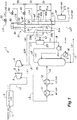
- Figure 1 is a diagram showing a liquefaction process flow in a liquefaction system 1 for the liquefaction of natural gas, not according to the present invention.
- Table 1 which will be shown hereinafter lists the results of a simulation of the liquefaction process in the system for the liquefaction of natural gas. The same is similarly true with Tables 2 to 12.
- Table 1 shows the temperature, the pressure, the flow rate and the molar composition of the natural gas that is to be liquefied at each of various points in the liquefaction system of the first embodiment.
- columns (i) to (ix) show the values at the respective points in the liquefaction system 1 denoted with corresponding roman numerals (i) to (ix) in Figure 1 .
- Natural gas containing about 80 to 98 mol% of methane is used as the material gas or the feedstock gas.
- the material gas also contains at least C5+ hydrocarbons by at least 0.1 mol% or BTX (benzene, toluene, xylene) by at least 1 ppm mol as heavier contents.
- BTX benzene, toluene, xylene
- the contents of the material gas other than methane are shown in column (i) of Table 1.
- the term "material gas” as used in this specification is not necessarily required to be in gaseous form, but may also be in liquid form according to various stages of liquefaction.
- the material gas is supplied to a water removal unit 2 via a line L1, and is freed from moisture in order to avoid troubles due to icing.
- the material gas supplied to the water removal unit 2 has a temperature of about 20 degrees Celsius, a pressure of about 5,830 kPaA and a flow rate of about 720,000 kg/hr.
- the water removal unit 2 may consist of towers filled with desiccant (such as a molecular sieve), and can reduce the water content of the material gas to less than 0.1 ppm mol.
- the water removal unit 2 may consist of any other known unit which is capable of removing water from the material gas below a desired level.
- the liquefaction system 1 may employ additional known facilities for performing preliminary process steps preceding the process step in the water removal unit 2, such as a separation unit for removing natural gas condensate, an acid gas removal unit for removing acid gases such as carbon dioxide and hydrogen sulfide and a mercury removal unit for removing mercury.
- the water removal unit 2 receives material gas from which impurities are removed by using such facilities.
- the material gas that is supplied to the water removal unit 2 is pre-processed such that the carbon dioxide (CO 2 ) content is less than 50 ppm mol, the hydrogen sulfide (H 2 S) content is less than 4 ppm mol, the sulfur content is less than 20 mg/Nm 3 , and the mercury content is less than 10 ng/Nm 3 .
- the source of the material gas may not be limited to any particular source, but may be obtained, not exclusively, from shale gas, tight sand gas and coal head methane in a pressurized state.
- the material gas may be supplied not only from the source such as a gas field via piping but also from storage tanks.
- the material gas from which water is removed in the water removal unit 2 is forwarded to a first expander 3 via a line L2.
- the first expander 3 consists of a turbine for reducing the pressure of the natural gas supplied thereto, and obtaining power (or energy) from the expansion of the natural gas under an isentropic condition. Owing to the expansion step (first expansion step) in the first expander 3, the pressure and the temperature of the material are reduced.
- the first expander 3 is provided with a common shaft 5 to a first compressor 4 (which will be discussed hereinafter) so that the power generated by the first expander 3 can be used for powering the first compressor 4.
- a suitable step-up gear unit may be placed between the first expander 3 and the first compressor 4.
- the first expander 3 reduces the temperature and the pressure of the material gas to about 8.3 degrees Celsius, a pressure of about 4,850 kPaA, respectively.
- the pressure of the material gas expelled from the first expander 3 is in the range of 3,000 kPaA to 5,500 kPaA (30 barA to 55 barA), or more preferably in the range of 3,500 kPaA to 5,000 kPaA (35 barA to 50 barA).
- the material gas from the first expander 3 is forwarded a cooler 11 via a line L3.
- a cooling unit (first cooling unit) is formed by connecting another cooler 12 to the downstream end of the cooler 11.
- the material gas is cooled by exchanging heat with refrigerants (first cooling step) in the first cooling unit 11, 12 in stages.
- the temperature of the material gas which has been cooled by the first cooling unit 11, 12 is in the range of from -20 to -50 degrees Celsius, or more preferably in the range of from -25 to -35 degrees Celsius. If the material gas introduced into the liquefaction system 1 is relatively high (higher than 100 barA, for instance), the first cooling unit 11, 12 may be omitted as the temperature of the material gas at the outlet of the first expander 3 is relatively low (-30 degrees Celsius, for instance).
- the possibility of omitting the cooling unit on the upstream side of the distillation unit 15 applies equally to the embodiments illustrated in Figures 5 to 7 which will be discussed hereinafter.
- the C3-MR (propane (C3) pre-cooled mixed refrigerant) system is used.
- the material gas is pre-cooled in the first cooling unit 11, 12 by using propane as the refrigerant, and is later super-cooled to an extremely low temperature for the liquefaction of the material gas in a refrigeration cycle using mixed refrigerants as will be discussed hereinafter.
- Propane refrigerants (C3R) for medium pressure (MP) and low pressure (LP) are used for cooling the material gas in a plurality of stages (in two stages in the illustrated embodiment) in the first cooling unit 11, 12.
- the first cooling unit 11, 12 forms a part of a per se known refrigeration cycle including compressors and condensers for the propane refrigerants.
- the liquefaction system 1 is not necessarily required to be based on the C3-MR system, but may use a cascade system in which a plurality of individual refrigeration cycles are formed by using corresponding refrigerants (such as methane, ethane and propane) having different boiling points, a DMR (double mixed refrigerant) system using a mixed medium such as a mixture of ethane and propane for a preliminary cooling process, and a MFC (mixed fluid cascade system) using different mixed refrigerants separately for the individual cycles of preliminary cooling, liquefaction and super cooling, among other possibilities.
- refrigerants such as methane, ethane and propane
- a DMR double mixed refrigerant
- MFC mixed fluid cascade system
- the material gas from the cooler 12 is forwarded to the distillation unit 15 via a line L4.
- the pressure of the material gas at this point should be below the critical pressures of methane and heavier components by means of the expansion in the first expander 3 and other optional processes.
- the distillation unit 15 essentially consists of a distillation tower internally provided with a plurality of shelves for removing heavier contents in the material gas (distillation step).
- the liquid consisting of the heavier contents is expelled via a line L5 connected to the bottom end of the distillation tower of the distillation unit 15.
- the liquid consisting of the heavier contents that is expelled from the distillation unit 15 via the line L5 has a temperature of about 177 degrees Celsius and a flow rate of about 20,000 kg/hr.
- the term “heavier contents” refer to components such as benzene having high freezing points and components having lower boiling points such as C5+ hydrocarbons.
- the line L5 includes a recirculation unit including a reboiler 16 for heating a part of the liquid expelled from the bottom of the distillation tower of the distillation unit 15 by exchanging heat with steam (or oil) supplied to the reboiler 16 from outside, and recirculating the heated liquid back to the distillation unit 15.
- the top fraction from the distillation unit 15 consisting of the lighter components of the material gas primarily consists of methane having a low boiling point, and this material gas is introduced into the liquefaction unit 21 via the line L6 to be cooled in the piping systems 22a and 22b.
- the material gas forwarded to the line L5 has a temperature of about - 45.6 degrees Celsius and a pressure of about 4,700 kPaA.
- the material gas freed from the heavier components in the distillation unit 15 contains less than 0.1 mol% of C5+ and less than 1 ppm mol of BTX (benzene, toluene and xylene).
- BTX benzene, toluene and xylene
- the liquefaction unit 21 essentially consists of a main heat exchanger in the liquefaction system 1, and this heat exchanger consists of a spool-wound type heat exchanger including a shell and coils of heat transfer tubes for conducting the material gas and the refrigerant.
- the liquefaction unit 21 defines a warm region Z1 situated in the lower part thereof for receiving the mixed refrigerant and having a highest temperature (range), an intermediate region Z2 situated in the intermediate part thereof and having a lower temperature than the warm region Z1 and a cold region situated in the upper part thereof for expelling the liquefied material gas and having a lowest temperature.
- the warm region Z1 consists of a higher warm region Z1a on a higher temperature side and a lower warm region Z1b on a lower temperature side.
- the piping systems 22a and 22b, as well as the piping systems 42a, 51a, and 42b and 51b through which the mixed refrigerant is conducted, are formed by the tube bundles provided in the higher warm region Z1a and the lower warm region Z1b, respectively.
- the temperature of the higher warm region Z1a is about -35 degrees Celsius on the upstream side (inlet side) of the material gas that is to be cooled, and about -50 degrees Celsius on the downstream side (outlet side) of the material gas.
- the temperature of the lower warm region Z1b is about -50 degrees Celsius on the upstream side of the material gas, and about -135 degrees Celsius on the downstream side of the material gas.
- the temperature of the intermediate region Z2 is about -65 degrees Celsius on the upstream side of the material gas, and about -135 degrees Celsius on the downstream side of the material gas.
- the temperature of the cold region Z3 is about -135 degrees Celsius on the upstream side of the material gas, and about -155 degrees Celsius on the downstream side of the material gas.
- the temperatures on the upstream side and the downstream side of each region are not limited to the values mentioned here, and the temperature in each of these parts may vary within a prescribed range ( ⁇ 5 degrees Celsius, for instance).
- the first gas-liquid separation vessel 23 separates the liquid phase component (condensate) of the material gas, and this liquid essentially consisting of hydrocarbons is recirculated back to the distillation unit 15 by a recirculation pump 24 provided in a line L8.
- the gas phase component of the material gas obtained in the first gas-liquid separation vessel 23 and mainly consisting of methane is forwarded to a first compressor 4 via a line L9.
- the material gas is passed through the line L8 at a flow rate of about 83,500 kg/hr, and is passed through the line L6 at a flow rate of about 780,000 kg/hr.
- the first gas-liquid separation vessel 23 may also be cooled by using a mixed refrigerant or an ethylene refrigerant.
- the first compressor 4 consists of a single stage centrifugal compressor having turbine blades for compressing the material gas, mounted on a shaft 5 common to the first expander 3.
- the material gas compressed by the first compressor 4 (first compression step) is introduced into the liquefaction unit 21 via a line L10.
- the material gas that is put out by the first compressor 4 to the line L10 has a temperature of about -51 degrees Celsius and a pressure of about 5,500 kPaA.
- the material gas introduced into the liquefaction unit 21 is compressed by the first compressor 4 preferably to a pressure exceeding at least 5,171 kPaA.
- a line L10 is connected to a piping system 30 positioned in the warm region Z1b of the liquefaction unit 21, and the upstream end of this piping system 30 is connected to a piping system 31 in the intermediate region Z2, and then to a piping system 32 positioned in the cold region Z3.
- the natural gas is forwarded to an LNG tank for storage purpose not shown in the drawings via an expansion valve 33 provided in a line L11.
- the material gas subjected to the liquefaction step acquires a temperature of -162 degrees Celsius and a pressure of about 120 kPaA in the downstream end of the expansion valve 33.
- the material gas flowing through the liquefaction unit 21 is cooled by a refrigeration cycle using mixed refrigerants.
- the mixed refrigerants may each contain nitrogen in addition to a mixture of hydrocarbons including methane, ethane and propane, but may also have other per se known compositions as long as the required cooling capability can be achieved.
- a high pressure (HP) mixed refrigerant (MR) is supplied to a refrigerant separator 41 via a line L12.
- the mixed refrigerant which makes up the liquid phase component in the refrigerant separator 41 is introduced into the liquefaction unit 21 via a line L13, and then flows upward in the liquefaction unit 21 through the piping systems 42a and 42b positioned in the warm regions Z1a and Z1b, respectively, and the piping system 43 positioned in the intermediate region Z2.
- the mixed refrigerant is then expanded in an expansion valve 44 provided in a line L14, and is partly flash vaporized.
- the mixed refrigerant After passing through the expansion valve 44, the mixed refrigerant is ejected downward (so as to oppose the flow of the material gas in the liquefaction unit 21) from a spray header 45 provided in an upper part of the intermediate region Z2.
- the mixed refrigerant ejected from the spray header 45 flows downward while exchanging heat with an intermediate tube bundle formed by the piping systems 31, 43 and 52 (the last piping system will be discussed hereinafter) positioned in the intermediate region Z2, and a lower tube bundle formed by the piping systems 22a, 22b, 30, 42a, 42b, 51a and 51b (the last two piping systems will be discussed hereinafter) positioned in the warm region Z1.
- the mixed refrigerant that makes up the gas phase of the refrigerant separator 41 is introduced into the liquefaction unit 21 via a line L15, and then flows upward in the liquefaction unit 21 by flowing through the piping systems 51a and 51b positioned in the warm regions Z1a and Z1b, the piping system 52 in the intermediate region Z2 and the piping system 53 positioned in the cold region Z3.
- the mixed refrigerant is then expanded in an expansion valve 54 provided in a line L16, and is partly flash vaporized.
- the mixed refrigerant that has passed through the expansion valve 54 is already cooled to a temperature below the boiling point of methane (about -167 degrees Celsius in this case), and is expelled downward from a spray header 55 positioned in an upper part of the cold region Z3 (or flows in opposite direction to the flow of the material gas in the liquefaction unit 21).
- the mixed refrigerant ejected from the spray header 55 flows downward while exchanging heat with an upper tube bundle formed by the piping systems 32 and 53 positioned in the cold region Z3, and after mixing with the mixed refrigerant ejected from the spray header 45 located below, flows downward while exchanging heat with the intermediate tube bundle formed by the piping systems 31, 43 and 52 positioned in the intermediate region Z2, and the lower tube bundle formed by the piping systems 22a, 22b, 30, 42a, 42b, 51a and 51b positioned in the warm region Z1.
- the mixed refrigerant ejected from the spray headers 45 and 55 is finally expelled via a line L17 connected to the bottom end of the liquefaction unit 21 as low pressure (LP) mixed refrigerant (MP) gas.
- LP low pressure
- MP mixed refrigerant
- the facilities for the mixed refrigerant provided in the liquefaction unit 21 (such as the refrigerant separator 41) form a part of a per se known refrigeration cycle for the mixed refrigerant, and the mixed refrigerant put out to the line L17 is recirculated to the refrigerant separator 41 via the line L12 after passing through compressors and condensers.
- the material gas introduced into the liquefaction system 1 is effectively liquefied after being processed in the expansion step, the cooling step, the distillation step, the compression step and the liquefaction step.
- This liquefaction system can be applied, for instance, to a base load liquefaction plant for producing liquefied natural gas (LNG) mainly consisting of methane from the material gas mined from a gas field.
- LNG liquefied natural gas
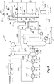
- Figures 2 and 3 are diagrams showing liquefaction process flows in conventional systems for the liquefaction of natural gas given as a first and a second example for comparison with the first embodiment of the present invention.
- the conventional liquefaction systems 101 and 201 for natural gas the parts corresponding to those of the liquefaction system of the first embodiment are denoted with like numerals.
- Tables 2 and 3 show the temperature, pressure, flow rate and molar fractions of the material gas in the liquefaction systems of the first and second examples for comparison, respectively.
- the liquefaction system 201 of the second example for comparison is based on the prior art disclosed in Patent Document 1 ( US 4,065,278 ).
- the liquefaction system 101 of the first example for comparison is not provided with the first expander 3 and the first compressor 4 used in the liquefaction system 1 of the first embodiment, and the material gas expelled from the water removal unit 2 is forwarded to a cooler 110 via a line L101.
- a cooler unit is formed by connecting a cooler 11 and a cooler 12 to the downstream end of the cooler 110 in a serial connection so that the material gas is sequentially cooled by exchanging heat in the three coolers 110, 11 and 12 which use a high pressure (HP), a medium pressure (MP) and a low pressure (LP) propane refrigerant, respectively.
- HP high pressure
- MP medium pressure
- LP low pressure propane refrigerant
- the material gas expelled from the cooler 12 in the downstream end has a temperature of about -34.5 degrees Celsius and a pressure of about 5,680 kPaA.
- the material gas is then depressurized by an expansion in an expansion valve 113 in a line L4, and is then introduced into a distillation unit 15.
- the material gas forming a gas phase component in the first gas-liquid separation vessel 23 and essentially consisting of methane is introduced into the piping system 31 positioned in the intermediate region Z2 of the liquefaction unit 21 via a line L102.
- the material gas that is put out from the first gas-liquid separation vessel 23 to a line L12 has a temperature of about -65.3 degrees Celsius and a pressure of about 4,400 kPaA. Table 2 No.
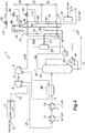
- the liquefaction system 201 of the second example for comparison is an improvement of the liquefaction system 101 of the first example for comparison, and is provided with a first expander 3 and a first compressor 4.
- the expander 3 is positioned on the downstream side of the cooling unit (consisting the three coolers 110, 11 and 12 in this case).
- the material gas expelled from the cooler 12 is forwarded to a separator 213 to be separated into gas and liquid components.
- the material gas that forms the gas phase component in the separator 213 is forwarded to the expander 3 to be expanded therein, and is then forwarded to the distillation unit 15 via a line L204.
- the part of the material gas that forms the liquid component in the separator 213 is put out to a line L205 provided with an expansion valve 214.
- the liquid that has been expanded in the expansion valve 214 is then forwarded to the distillation unit 15 via the line L204 along with the material gas from the expander 3.
- the liquefaction system 201 is similar to that of the first embodiment as far as the part thereof downstream of the distillation unit 15 is concerned, and the material gas that has been put out to the line L10 by the compressor 4 has a temperature of about -54.7 degrees Celsius and a pressure of about 5,120 kPaA.
- the liquefaction system 1 allows a greater power to be produced by expanding material gas of higher temperature and higher pressure because the first expander 3 is positioned on the upstream side of the first cooling unit 11, 12, as compared to the liquefaction system 201 of the second example which has the expander 3 positioned on the downstream side of the cooling unit 110, 11, 12.
- the first compressor 4 can be driven with an increased power (or the outlet pressure of the first compressor 4 can be increased) so that the pressure of the material gas introduced into the liquefaction unit 21 can be increased, and the efficiency of the liquefaction process in the liquefaction unit 21 can be advantageously increased.
- the liquefaction system 1 provides an additional advantage of reducing the required cooling capacity of the cooling unit (thereby allowing the cooler 110 in the second example for comparison to be omitted) because the temperature of the material gas is reduced by the expansion of the material gas in the first expander 3 owing to the positioning of the first expander 3 on the upstream side of the first cooling unit 11, 12.
- the gas-liquid separation vessel (separator 213) for removing the condensate of the material gas placed between the cooling unit and the expander 3 may be omitted.
- Figures 4 , 5 and 6 are diagrams showing liquefaction process flows in systems for the liquefaction of natural gas given as a first, second, and third modifications of the liquefaction system 1, respectively.
- the parts corresponding to those of the liquefaction system 1 are denoted with like numerals and omitted from the following discussion except for the matters that will be discussed in the following.
- a heat exchanger 69 is provided between the line L4 and the line L9.
- the material gas that is separated in the first gas-liquid separation vessel 23 as the gas phase component and flows through the line L9 is heated by exchanging heat with the material gas flowing from the cooling unit 12 to the distillation unit 15 via the line L4, before being introduced into the first compressor 4.
- the material gas compressed by the first compressor 4 is introduced into the liquefaction unit 21 via the line L10.
- the downstream end of the line L10 is connected to a piping system 30 positioned in the warm region Z1 demonstrating the highest temperature in the liquefaction unit 21.
- the piping system 30 forms a tube bundle that is positioned in the warm region Z1 jointly with a piping system 22 into which the top fraction of the distillation unit 15 is introduced, and a piping system 42 and a piping system 51 through which a mixed refrigerant flows.
- the temperature of the material gas in the line L10 after the compression can be brought close to the temperature at the point of introduction (piping system 30) in the liquefaction unit 21 (preferably with a deviation of less than 10 degrees Celsius) so that the thermal load on the liquefaction unit 21 can be reduced (or the generation of thermal stress can be minimized).
- the arrangement of the heat exchanger 69 in the first modification can be freely changed as long as the temperature of the material gas in the line L10 after the compression can be brought close to the temperature at the introduction point of the liquefaction unit 21.
- the heat exchanger 69 is provided between the line L4 and the line L10.
- the material gas compressed by the first compressor 4 and flowing through the line L10 is cooled by exchanging heat with the material gas flowing through the line L4 before being introduced into the liquefaction unit 21.
- the temperature of the material gas that is introduced into the liquefaction unit 1 can be controlled with ease.
- the heat exchanger 69 is provided between the line L4 and the line L6. Therefore, the material gas that is separated as a top fraction from the distillation unit 15 and flows through the line L6 is heated by exchanging heat with the material gas flowing through the line L4, before being introduced into the liquefaction unit 21 (the piping system 22).
- the temperature of the material gas can be raised to an appropriate level by exchanging heat in the heat exchanger 69.
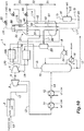
- Figure 7 is a diagram showing a liquefaction process flow in a system for the liquefaction of natural gas according to the invention, given as a modification of the liquefaction system 1.
- the parts corresponding to those of the liquefaction system 1 of the first embodiment are denoted with like numerals and omitted from the following discussion except for the matters that will be discussed in the following.
- the modification according to the invention is similar to the third modification, but further modification of the liquefaction system 1 includes a heat exchanger 69 that is provided between the line L4 and the line L6. Therefore, the material gas that is separated as a top fraction from the distillation unit 15 and flows through the line L6 is heated by exchanging heat with the material gas flowing through the line L4, before being introduced into the liquefaction unit 21 (the piping system 22).
- the temperature of the material gas can be raised to an appropriate level by exchanging heat in the heat exchanger 69.
- the modification further includes a heat exchanger 79 provided between the line L9 and the line L10.
- a cooler 80 using a low pressure (LP) propane refrigerant (C3R) is further provided in the line L10.
- LP low pressure
- C3R propane refrigerant
- the downstream end of the line L10 is connected to a piping system 31 positioned in the intermediate region Z2.
- the material gas expelled from the first compressor 4 can be introduced into the intermediate region Z2. Therefore, the tube bundle in the warm region Z1 can be formed by the three piping systems 22, 42 and 51, and the tube bundle in the intermediate region Z2 can be formed by the three piping systems 31, 43 and 52.
- the arrangement of the piping systems in the warm region Z1 and the intermediate region Z2 can be optimized (by uniformly spreading the piping systems among the different regions) as compared to the arrangement of the third modification so that the size of the liquefaction unit 21 is prevented from becoming excessively great.
- the fifth cooler 80 uses a propane refrigerant similarly to the first and second coolers 11 and 12 in the illustrated embodiment, by may also use other forms of air-cooled or water-cooled coolers.
- Figure 10 is a diagram showing a liquefaction process flow in a system for the liquefaction of natural gas according to the invention as a fifth modification of the liquefaction system 1.
- the parts corresponding to those of the liquefaction system 1 of the first embodiment are denoted with like numerals and omitted from the following discussion except for the matters that will be discussed in the following.
- This modification according to the invention is similar to the modification according to the invention discussed above, but the fifth cooler 80 of the fourth modification is omitted, and a heat exchanger 100 is added between the line L6 leading from the distillation unit 15 and the line L10 leading from the first compressor 4.
- the material gas expelled from the first compressor 4 to the line L10 is cooled by the material gas (top fraction) expelled from the distillation unit 15 to the line L6, instead of being cooled by the fifth cooler 80, and is introduced into a heat exchanger 79 similarly to that of the fourth modification.
- the material gas expelled from the distillation unit 15 is introduced into the liquefaction unit 21 via the line L6 following the heat exchange, and is then cooled by the piping system 22.
- the cooling of the material gas by the fifth cooler 80 as in the previous embodiment may be augmented or replaced by the heat exchange in the heat exchanger 100.
- Figure 8 is a diagram showing a liquefaction process flow in a system for the liquefaction of natural gas not according to the present invention.
- the parts corresponding to those of the liquefaction system 1 of the first embodiment is denoted with like numerals and omitted from the following discussion except for the matters that will be discussed in the following.
- the material gas in the liquefaction system 1 of this embodiment, rich gas containing 88 mol% of methane is used as the material gas.
- the material gas that is separated as a top fraction in the distillation unit 15 is directly introduced into the first compressor 4 to be compressed thereby via a line L19.
- the material gas is then pre-cooled in the piping system 22 in the warm region Z1, and forwarded to a first gas-liquid separation vessel 23 via a line L21.
- the first gas-liquid separation vessel 23 separates a liquid phase component (condensate) of the material gas, and the hydrocarbons in liquid form forming the liquid phase component is recirculated to the distillation unit 15 via an expansion valve 89 provided in a line L22. Meanwhile, the material gas mainly consisting of methane and forming the liquid phase component in the first gas-liquid separation vessel 23 is forwarded to the piping system 31 in the liquefaction unit 21 via a line L23.
- the temperature of the material gas can be brought close to the temperature level of the warm region Z1 of the liquefaction unit 21. Furthermore, because the material gas is cooled in the warm region Z1 (piping system 22) of the liquefaction unit 21, and the gas phase component expelled from the first gas-liquid separation vessel 23 is introduced into the intermediate region Z2 (piping system 31), the temperature of the material gas can be brought close to the temperature level of the intermediate region Z2 of the liquefaction unit 21 with ease.
- the recirculation pump 24 provided in the recirculation line (line L21) extending from the first gas-liquid separation vessel 23 to the distillation unit 15 in some of the embodiments including the first embodiment can be omitted.
- the material gas separated as the top fraction in the distillation unit 15 is forwarded directly to the first compressor 4 via the line L19 to be compressed, the material gas compressed by the first compressor 4 is cooled in the warm region Z1 of the liquefaction unit 21, the cooled material gas is separated in the first gas-liquid separation vessel 23, and the separated gas phase component of the material gas is introduced into the intermediate region Z2 (downstream of the warm region Z1) of the liquefaction unit 21, as is the case with the present embodiment, the temperature of the material gas can be maintained within an appropriate range (or the temperature of the material gas can be brought close to the temperature level at the introduction point of the liquefaction unit 21).
- Figure 9 is a diagram showing liquefaction process flows in a system for the liquefaction of natural gas not according to the present invention.
- the parts corresponding to those of the liquefaction system 1 of the first embodiment is denoted with like numerals and omitted from the following discussion except for the matters that will be discussed in the following.
- the liquefaction system 1 of this modification includes a heat exchanger 69 positioned between the line L4 and the line L20 so that the material gas expelled from the first compressor 4 and conducted through the line L20 is heated by the exchange of heat with the material gas flowing through the line L4, and is then introduced into the piping system positioned in the warm region Z1 of the liquefaction unit 21.
- the material gas heated in the heat exchanger 69 is directly introduced into the liquefaction unit 21 without the intervention of the first compressor 4 so that the temperature of the material gas that is introduced into the liquefaction unit 21 can be controlled with ease.
- the positioning of the heat exchanger 69 in this modification can be changed variously without departing from the spirit of the present invention as long as the temperature of the material gas in the line L20 following the compression can be brought close to the temperature at the introduction point of the liquefaction unit 21.
Landscapes
- Engineering & Computer Science (AREA)
- Physics & Mathematics (AREA)
- Mechanical Engineering (AREA)
- Thermal Sciences (AREA)
- General Engineering & Computer Science (AREA)
- Chemical & Material Sciences (AREA)
- Oil, Petroleum & Natural Gas (AREA)
- Chemical Kinetics & Catalysis (AREA)
- General Chemical & Material Sciences (AREA)
- Separation By Low-Temperature Treatments (AREA)
Applications Claiming Priority (4)
| Application Number | Priority Date | Filing Date | Title |
|---|---|---|---|
| JP2013270011 | 2013-12-26 | ||
| JP2014050786A JP6225049B2 (ja) | 2013-12-26 | 2014-03-13 | 天然ガスの液化システム及び液化方法 |
| EP14873799.2A EP3091319B1 (en) | 2013-12-26 | 2014-12-26 | Natural gas liquefying system and liquefying method |
| PCT/JP2014/006501 WO2015098124A1 (ja) | 2013-12-26 | 2014-12-26 | 天然ガスの液化システム及び液化方法 |
Related Parent Applications (2)
| Application Number | Title | Priority Date | Filing Date |
|---|---|---|---|
| EP14873799.2A Division EP3091319B1 (en) | 2013-12-26 | 2014-12-26 | Natural gas liquefying system and liquefying method |
| EP14873799.2A Division-Into EP3091319B1 (en) | 2013-12-26 | 2014-12-26 | Natural gas liquefying system and liquefying method |
Publications (2)
| Publication Number | Publication Date |
|---|---|
| EP3168558A1 EP3168558A1 (en) | 2017-05-17 |
| EP3168558B1 true EP3168558B1 (en) | 2019-05-29 |
Family
ID=53478019
Family Applications (2)
| Application Number | Title | Priority Date | Filing Date |
|---|---|---|---|
| EP16201992.1A Active EP3168558B1 (en) | 2013-12-26 | 2014-12-26 | System and method for liquefaction of natural gas |
| EP14873799.2A Active EP3091319B1 (en) | 2013-12-26 | 2014-12-26 | Natural gas liquefying system and liquefying method |
Family Applications After (1)
| Application Number | Title | Priority Date | Filing Date |
|---|---|---|---|
| EP14873799.2A Active EP3091319B1 (en) | 2013-12-26 | 2014-12-26 | Natural gas liquefying system and liquefying method |
Country Status (14)
| Country | Link |
|---|---|
| US (3) | US20160313056A1 (https=) |
| EP (2) | EP3168558B1 (https=) |
| JP (1) | JP6225049B2 (https=) |
| KR (2) | KR101894076B1 (https=) |
| CN (2) | CN107339853B (https=) |
| AP (3) | AP2016009308A0 (https=) |
| AU (3) | AU2014371866B9 (https=) |
| CA (3) | CA2934435A1 (https=) |
| ES (1) | ES2838498T3 (https=) |
| MY (2) | MY176671A (https=) |
| PE (2) | PE20161119A1 (https=) |
| RU (3) | RU2651007C2 (https=) |
| SA (2) | SA516380183B1 (https=) |
| WO (2) | WO2015098124A1 (https=) |
Families Citing this family (20)
| Publication number | Priority date | Publication date | Assignee | Title |
|---|---|---|---|---|
| JP6517251B2 (ja) * | 2013-12-26 | 2019-05-22 | 千代田化工建設株式会社 | 天然ガスの液化システム及び液化方法 |
| US10619918B2 (en) * | 2015-04-10 | 2020-04-14 | Chart Energy & Chemicals, Inc. | System and method for removing freezing components from a feed gas |
| TWI707115B (zh) * | 2015-04-10 | 2020-10-11 | 美商圖表能源與化學有限公司 | 混合製冷劑液化系統和方法 |
| FR3039080B1 (fr) * | 2015-07-23 | 2019-05-17 | L'air Liquide, Societe Anonyme Pour L'etude Et L'exploitation Des Procedes Georges Claude | Methode de purification d'un gaz riche en hydrocarbures |
| FR3052241A1 (fr) | 2016-06-02 | 2017-12-08 | L'air Liquide Sa Pour L'etude Et L'exploitation Des Procedes Georges Claude | Procede de purification de gaz naturel et de liquefaction de dioxyde de carbone |
| FR3053771B1 (fr) * | 2016-07-06 | 2019-07-19 | Saipem S.P.A. | Procede de liquefaction de gaz naturel et de recuperation d'eventuels liquides du gaz naturel comprenant deux cycles refrigerant semi-ouverts au gaz naturel et un cycle refrigerant ferme au gaz refrigerant |
| US11668522B2 (en) * | 2016-07-21 | 2023-06-06 | Air Products And Chemicals, Inc. | Heavy hydrocarbon removal system for lean natural gas liquefaction |
| US10539364B2 (en) * | 2017-03-13 | 2020-01-21 | General Electric Company | Hydrocarbon distillation |
| JP7026470B2 (ja) * | 2017-09-29 | 2022-02-28 | レール・リキード-ソシエテ・アノニム・プール・レテュード・エ・レクスプロワタシオン・デ・プロセデ・ジョルジュ・クロード | 天然ガスの製造装置および天然ガスの製造方法 |
| US10866022B2 (en) * | 2018-04-27 | 2020-12-15 | Air Products And Chemicals, Inc. | Method and system for cooling a hydrocarbon stream using a gas phase refrigerant |
| WO2020040952A1 (en) * | 2018-08-22 | 2020-02-27 | Exxonmobil Upstream Research Company | Primary loop start-up method for a high pressure expander process |
| WO2020040951A1 (en) | 2018-08-22 | 2020-02-27 | Exxonmobil Upstream Research Company | Managing make-up gas composition variation for a high pressure expander process |
| SG11202101058QA (en) | 2018-08-22 | 2021-03-30 | Exxonmobil Upstream Res Co | Heat exchanger configuration for a high pressure expander process and a method of natural gas liquefaction using the same |
| TWI746977B (zh) * | 2019-01-22 | 2021-11-21 | 法商液態空氣喬治斯克勞帝方法研究開發股份有限公司 | 氣體液化方法及氣體液化裝置 |
| CN110185506B (zh) * | 2019-05-27 | 2022-02-08 | 西南石油大学 | 一种天然气调压站压力能综合利用系统 |
| JP7355979B2 (ja) * | 2019-09-26 | 2023-10-04 | レール・リキード-ソシエテ・アノニム・プール・レテュード・エ・レクスプロワタシオン・デ・プロセデ・ジョルジュ・クロード | ガス液化装置 |
| CN111664611B (zh) * | 2020-05-06 | 2023-05-09 | 杭州电子科技大学 | 一种对石油开采钻具进行冷却的制冷循环装置 |
| CN111692781A (zh) * | 2020-05-06 | 2020-09-22 | 杭州电子科技大学 | 正辛烷在对钻具进行冷却的制冷循环中作为制冷剂的应用 |
| CA3178788A1 (en) * | 2020-06-03 | 2021-12-09 | Chart Energy & Chemicals, Inc. | Gas stream component removal system and method |
| CN112377176B (zh) * | 2020-11-17 | 2023-09-26 | 中国石油天然气股份有限公司 | 一种页岩气高产井组快速确定方法及装置 |
Family Cites Families (23)
| Publication number | Priority date | Publication date | Assignee | Title |
|---|---|---|---|---|
| DE1268162B (de) * | 1965-07-28 | 1968-05-16 | Linde Ag | Verfahren zum Zerlegen eines Gasgemisches |
| US4004430A (en) * | 1974-09-30 | 1977-01-25 | The Lummus Company | Process and apparatus for treating natural gas |
| US4150962A (en) * | 1975-12-15 | 1979-04-24 | Uop Inc. | Pretreatment of raw natural gas prior to liquefaction |
| US4065278A (en) | 1976-04-02 | 1977-12-27 | Air Products And Chemicals, Inc. | Process for manufacturing liquefied methane |
| JPS5472203A (en) * | 1977-11-21 | 1979-06-09 | Air Prod & Chem | Production of liquefied methane |
| US4445917A (en) * | 1982-05-10 | 1984-05-01 | Air Products And Chemicals, Inc. | Process for liquefied natural gas |
| US4445916A (en) * | 1982-08-30 | 1984-05-01 | Newton Charles L | Process for liquefying methane |
| GB8411686D0 (en) * | 1984-05-08 | 1984-06-13 | Stothers W R | Recovery of ethane and natural gas liquids |
| US5615561A (en) * | 1994-11-08 | 1997-04-01 | Williams Field Services Company | LNG production in cryogenic natural gas processing plants |
| RU2088866C1 (ru) * | 1995-04-21 | 1997-08-27 | Всероссийский научно-исследовательский институт природных газов и газовых технологий | Способ подготовки природного газа к транспорту |
| US6401486B1 (en) * | 2000-05-18 | 2002-06-11 | Rong-Jwyn Lee | Enhanced NGL recovery utilizing refrigeration and reflux from LNG plants |
| US6793712B2 (en) * | 2002-11-01 | 2004-09-21 | Conocophillips Company | Heat integration system for natural gas liquefaction |
| KR20080108138A (ko) * | 2006-03-24 | 2008-12-11 | 쉘 인터내셔날 리써취 마트샤피지 비.브이. | 탄화수소 스트림을 액화시키는 방법 및 장치 |
| RU2436024C2 (ru) * | 2006-05-19 | 2011-12-10 | Шелл Интернэшнл Рисерч Маатсхаппий Б.В. | Способ и устройство для обработки потока углеводородов |
| WO2007148122A2 (en) * | 2006-06-23 | 2007-12-27 | T Baden Hardstaff Limited | Process and device for producing lng |
| CN101108978B (zh) * | 2006-07-19 | 2011-04-20 | 吕应中 | 碳氢化合物气体处理方法与装置 |
| US8256243B2 (en) * | 2006-12-16 | 2012-09-04 | Kellogg Brown & Root Llc | Integrated olefin recovery process |
| DE102007007581A1 (de) * | 2007-02-15 | 2008-08-21 | Linde Ag | Verfahren und Vorrichtung zur Trennung eines Gasgemisches |
| EP2165139A2 (en) * | 2007-07-12 | 2010-03-24 | Shell Internationale Research Maatschappij B.V. | Method and apparatus for liquefying a gaseous hydrocarbon stream |
| US20090282865A1 (en) * | 2008-05-16 | 2009-11-19 | Ortloff Engineers, Ltd. | Liquefied Natural Gas and Hydrocarbon Gas Processing |
| US20100287982A1 (en) * | 2009-05-15 | 2010-11-18 | Ortloff Engineers, Ltd. | Liquefied Natural Gas and Hydrocarbon Gas Processing |
| MY164712A (en) * | 2010-09-03 | 2018-01-30 | Twister Bv | Refining system and method for refining a feed gas stream |
| FR2992972B1 (fr) * | 2012-07-05 | 2014-08-15 | Technip France | Procede de production d'un gaz naturel traite, d'une coupe riche en hydrocarbures en c3+, et eventuellement d'un courant riche en ethane, et installation associee |
-
2014
- 2014-03-13 JP JP2014050786A patent/JP6225049B2/ja active Active
- 2014-12-26 AP AP2016009308A patent/AP2016009308A0/en unknown
- 2014-12-26 MY MYPI2016702301A patent/MY176671A/en unknown
- 2014-12-26 KR KR1020167030036A patent/KR101894076B1/ko active Active
- 2014-12-26 AU AU2014371866A patent/AU2014371866B9/en active Active
- 2014-12-26 PE PE2016000954A patent/PE20161119A1/es unknown
- 2014-12-26 KR KR1020167020287A patent/KR101840721B1/ko active Active
- 2014-12-26 MY MYPI2020003682A patent/MY200229A/en unknown
- 2014-12-26 CA CA2934435A patent/CA2934435A1/en not_active Abandoned
- 2014-12-26 CN CN201611162705.9A patent/CN107339853B/zh active Active
- 2014-12-26 RU RU2016130314A patent/RU2651007C2/ru active
- 2014-12-26 AU AU2014371867A patent/AU2014371867A1/en not_active Abandoned
- 2014-12-26 CN CN201480071324.2A patent/CN106062495B/zh active Active
- 2014-12-26 EP EP16201992.1A patent/EP3168558B1/en active Active
- 2014-12-26 PE PE2016002091A patent/PE20170506A1/es unknown
- 2014-12-26 RU RU2016144151A patent/RU2668303C1/ru active
- 2014-12-26 US US15/104,564 patent/US20160313056A1/en not_active Abandoned
- 2014-12-26 CA CA2934895A patent/CA2934895C/en active Active
- 2014-12-26 AP AP2016009511A patent/AP2016009511A0/en unknown
- 2014-12-26 CA CA3029950A patent/CA3029950C/en active Active
- 2014-12-26 EP EP14873799.2A patent/EP3091319B1/en active Active
- 2014-12-26 WO PCT/JP2014/006501 patent/WO2015098124A1/ja not_active Ceased
- 2014-12-26 WO PCT/JP2014/006502 patent/WO2015098125A1/ja not_active Ceased
- 2014-12-26 RU RU2016130315A patent/RU2016130315A/ru not_active Application Discontinuation
- 2014-12-26 US US15/108,042 patent/US20170160008A9/en not_active Abandoned
- 2014-12-26 AP AP2016009309A patent/AP2016009309A0/en unknown
- 2014-12-26 ES ES14873799T patent/ES2838498T3/es active Active
-
2016
- 2016-06-24 SA SA516380183A patent/SA516380183B1/ar unknown
- 2016-06-24 SA SA516371407A patent/SA516371407B1/ar unknown
- 2016-10-14 US US15/293,485 patent/US20170030633A1/en not_active Abandoned
- 2016-10-24 AU AU2016250325A patent/AU2016250325B2/en active Active
Non-Patent Citations (1)
| Title |
|---|
| None * |
Also Published As
Similar Documents
| Publication | Publication Date | Title |
|---|---|---|
| EP3168558B1 (en) | System and method for liquefaction of natural gas | |
| CN101108977B (zh) | 在液化天然气制备中的一体化ngl回收 | |
| AU2015231891B2 (en) | Liquefied natural gas facility employing an optimized mixed refrigerant system | |
| JP6503024B2 (ja) | リーンな天然ガス液化のための重質炭化水素除去システム | |
| JP6702919B2 (ja) | 混合冷媒冷却プロセスおよびシステム | |
| JP6517251B2 (ja) | 天然ガスの液化システム及び液化方法 | |
| US12025370B2 (en) | Reverse Brayton LNG production process |
Legal Events
| Date | Code | Title | Description |
|---|---|---|---|
| PUAI | Public reference made under article 153(3) epc to a published international application that has entered the european phase |
Free format text: ORIGINAL CODE: 0009012 |
|
| STAA | Information on the status of an ep patent application or granted ep patent |
Free format text: STATUS: THE APPLICATION HAS BEEN PUBLISHED |
|
| AC | Divisional application: reference to earlier application |
Ref document number: 3091319 Country of ref document: EP Kind code of ref document: P |
|
| AK | Designated contracting states |
Kind code of ref document: A1 Designated state(s): AL AT BE BG CH CY CZ DE DK EE ES FI FR GB GR HR HU IE IS IT LI LT LU LV MC MK MT NL NO PL PT RO RS SE SI SK SM TR |
|
| AX | Request for extension of the european patent |
Extension state: BA ME |
|
| STAA | Information on the status of an ep patent application or granted ep patent |
Free format text: STATUS: REQUEST FOR EXAMINATION WAS MADE |
|
| 17P | Request for examination filed |
Effective date: 20171117 |
|
| RBV | Designated contracting states (corrected) |
Designated state(s): AL AT BE BG CH CY CZ DE DK EE ES FI FR GB GR HR HU IE IS IT LI LT LU LV MC MK MT NL NO PL PT RO RS SE SI SK SM TR |
|
| STAA | Information on the status of an ep patent application or granted ep patent |
Free format text: STATUS: EXAMINATION IS IN PROGRESS |
|
| 17Q | First examination report despatched |
Effective date: 20180307 |
|
| GRAP | Despatch of communication of intention to grant a patent |
Free format text: ORIGINAL CODE: EPIDOSNIGR1 |
|
| STAA | Information on the status of an ep patent application or granted ep patent |
Free format text: STATUS: GRANT OF PATENT IS INTENDED |
|
| INTG | Intention to grant announced |
Effective date: 20190103 |
|
| GRAS | Grant fee paid |
Free format text: ORIGINAL CODE: EPIDOSNIGR3 |
|
| GRAA | (expected) grant |
Free format text: ORIGINAL CODE: 0009210 |
|
| STAA | Information on the status of an ep patent application or granted ep patent |
Free format text: STATUS: THE PATENT HAS BEEN GRANTED |
|
| RIN1 | Information on inventor provided before grant (corrected) |
Inventor name: TRUONG, TIMOTHY Inventor name: KIKKAWA, YOSHITSUGI Inventor name: LIU, YU NAN Inventor name: SAKAI, KOICHIRO |
|
| AC | Divisional application: reference to earlier application |
Ref document number: 3091319 Country of ref document: EP Kind code of ref document: P |
|
| AK | Designated contracting states |
Kind code of ref document: B1 Designated state(s): AL AT BE BG CH CY CZ DE DK EE ES FI FR GB GR HR HU IE IS IT LI LT LU LV MC MK MT NL NO PL PT RO RS SE SI SK SM TR |
|
| REG | Reference to a national code |
Ref country code: GB Ref legal event code: FG4D |
|
| REG | Reference to a national code |
Ref country code: CH Ref legal event code: EP |
|
| REG | Reference to a national code |
Ref country code: AT Ref legal event code: REF Ref document number: 1138508 Country of ref document: AT Kind code of ref document: T Effective date: 20190615 |
|
| REG | Reference to a national code |
Ref country code: DE Ref legal event code: R096 Ref document number: 602014047708 Country of ref document: DE |
|
| REG | Reference to a national code |
Ref country code: IE Ref legal event code: FG4D |
|
| REG | Reference to a national code |
Ref country code: NL Ref legal event code: FP |
|
| REG | Reference to a national code |
Ref country code: NO Ref legal event code: T2 Effective date: 20190529 |
|
| REG | Reference to a national code |
Ref country code: LT Ref legal event code: MG4D |
|
| PG25 | Lapsed in a contracting state [announced via postgrant information from national office to epo] |
Ref country code: LT Free format text: LAPSE BECAUSE OF FAILURE TO SUBMIT A TRANSLATION OF THE DESCRIPTION OR TO PAY THE FEE WITHIN THE PRESCRIBED TIME-LIMIT Effective date: 20190529 Ref country code: ES Free format text: LAPSE BECAUSE OF FAILURE TO SUBMIT A TRANSLATION OF THE DESCRIPTION OR TO PAY THE FEE WITHIN THE PRESCRIBED TIME-LIMIT Effective date: 20190529 Ref country code: SE Free format text: LAPSE BECAUSE OF FAILURE TO SUBMIT A TRANSLATION OF THE DESCRIPTION OR TO PAY THE FEE WITHIN THE PRESCRIBED TIME-LIMIT Effective date: 20190529 Ref country code: PT Free format text: LAPSE BECAUSE OF FAILURE TO SUBMIT A TRANSLATION OF THE DESCRIPTION OR TO PAY THE FEE WITHIN THE PRESCRIBED TIME-LIMIT Effective date: 20190930 Ref country code: HR Free format text: LAPSE BECAUSE OF FAILURE TO SUBMIT A TRANSLATION OF THE DESCRIPTION OR TO PAY THE FEE WITHIN THE PRESCRIBED TIME-LIMIT Effective date: 20190529 Ref country code: AL Free format text: LAPSE BECAUSE OF FAILURE TO SUBMIT A TRANSLATION OF THE DESCRIPTION OR TO PAY THE FEE WITHIN THE PRESCRIBED TIME-LIMIT Effective date: 20190529 Ref country code: FI Free format text: LAPSE BECAUSE OF FAILURE TO SUBMIT A TRANSLATION OF THE DESCRIPTION OR TO PAY THE FEE WITHIN THE PRESCRIBED TIME-LIMIT Effective date: 20190529 |
|
| PG25 | Lapsed in a contracting state [announced via postgrant information from national office to epo] |
Ref country code: GR Free format text: LAPSE BECAUSE OF FAILURE TO SUBMIT A TRANSLATION OF THE DESCRIPTION OR TO PAY THE FEE WITHIN THE PRESCRIBED TIME-LIMIT Effective date: 20190830 Ref country code: LV Free format text: LAPSE BECAUSE OF FAILURE TO SUBMIT A TRANSLATION OF THE DESCRIPTION OR TO PAY THE FEE WITHIN THE PRESCRIBED TIME-LIMIT Effective date: 20190529 Ref country code: BG Free format text: LAPSE BECAUSE OF FAILURE TO SUBMIT A TRANSLATION OF THE DESCRIPTION OR TO PAY THE FEE WITHIN THE PRESCRIBED TIME-LIMIT Effective date: 20190829 Ref country code: RS Free format text: LAPSE BECAUSE OF FAILURE TO SUBMIT A TRANSLATION OF THE DESCRIPTION OR TO PAY THE FEE WITHIN THE PRESCRIBED TIME-LIMIT Effective date: 20190529 |
|
| REG | Reference to a national code |
Ref country code: AT Ref legal event code: MK05 Ref document number: 1138508 Country of ref document: AT Kind code of ref document: T Effective date: 20190529 |
|
| PG25 | Lapsed in a contracting state [announced via postgrant information from national office to epo] |
Ref country code: CZ Free format text: LAPSE BECAUSE OF FAILURE TO SUBMIT A TRANSLATION OF THE DESCRIPTION OR TO PAY THE FEE WITHIN THE PRESCRIBED TIME-LIMIT Effective date: 20190529 Ref country code: SK Free format text: LAPSE BECAUSE OF FAILURE TO SUBMIT A TRANSLATION OF THE DESCRIPTION OR TO PAY THE FEE WITHIN THE PRESCRIBED TIME-LIMIT Effective date: 20190529 Ref country code: RO Free format text: LAPSE BECAUSE OF FAILURE TO SUBMIT A TRANSLATION OF THE DESCRIPTION OR TO PAY THE FEE WITHIN THE PRESCRIBED TIME-LIMIT Effective date: 20190529 Ref country code: AT Free format text: LAPSE BECAUSE OF FAILURE TO SUBMIT A TRANSLATION OF THE DESCRIPTION OR TO PAY THE FEE WITHIN THE PRESCRIBED TIME-LIMIT Effective date: 20190529 Ref country code: DK Free format text: LAPSE BECAUSE OF FAILURE TO SUBMIT A TRANSLATION OF THE DESCRIPTION OR TO PAY THE FEE WITHIN THE PRESCRIBED TIME-LIMIT Effective date: 20190529 Ref country code: EE Free format text: LAPSE BECAUSE OF FAILURE TO SUBMIT A TRANSLATION OF THE DESCRIPTION OR TO PAY THE FEE WITHIN THE PRESCRIBED TIME-LIMIT Effective date: 20190529 |
|
| PG25 | Lapsed in a contracting state [announced via postgrant information from national office to epo] |
Ref country code: IT Free format text: LAPSE BECAUSE OF FAILURE TO SUBMIT A TRANSLATION OF THE DESCRIPTION OR TO PAY THE FEE WITHIN THE PRESCRIBED TIME-LIMIT Effective date: 20190529 Ref country code: SM Free format text: LAPSE BECAUSE OF FAILURE TO SUBMIT A TRANSLATION OF THE DESCRIPTION OR TO PAY THE FEE WITHIN THE PRESCRIBED TIME-LIMIT Effective date: 20190529 |
|
| REG | Reference to a national code |
Ref country code: DE Ref legal event code: R097 Ref document number: 602014047708 Country of ref document: DE |
|
| PG25 | Lapsed in a contracting state [announced via postgrant information from national office to epo] |
Ref country code: TR Free format text: LAPSE BECAUSE OF FAILURE TO SUBMIT A TRANSLATION OF THE DESCRIPTION OR TO PAY THE FEE WITHIN THE PRESCRIBED TIME-LIMIT Effective date: 20190529 |
|
| PLBE | No opposition filed within time limit |
Free format text: ORIGINAL CODE: 0009261 |
|
| STAA | Information on the status of an ep patent application or granted ep patent |
Free format text: STATUS: NO OPPOSITION FILED WITHIN TIME LIMIT |
|
| PG25 | Lapsed in a contracting state [announced via postgrant information from national office to epo] |
Ref country code: PL Free format text: LAPSE BECAUSE OF FAILURE TO SUBMIT A TRANSLATION OF THE DESCRIPTION OR TO PAY THE FEE WITHIN THE PRESCRIBED TIME-LIMIT Effective date: 20190529 |
|
| 26N | No opposition filed |
Effective date: 20200303 |
|
| PG25 | Lapsed in a contracting state [announced via postgrant information from national office to epo] |
Ref country code: SI Free format text: LAPSE BECAUSE OF FAILURE TO SUBMIT A TRANSLATION OF THE DESCRIPTION OR TO PAY THE FEE WITHIN THE PRESCRIBED TIME-LIMIT Effective date: 20190529 |
|
| REG | Reference to a national code |
Ref country code: CH Ref legal event code: PL |
|
| REG | Reference to a national code |
Ref country code: BE Ref legal event code: MM Effective date: 20191231 |
|
| PG25 | Lapsed in a contracting state [announced via postgrant information from national office to epo] |
Ref country code: MC Free format text: LAPSE BECAUSE OF FAILURE TO SUBMIT A TRANSLATION OF THE DESCRIPTION OR TO PAY THE FEE WITHIN THE PRESCRIBED TIME-LIMIT Effective date: 20190529 |
|
| PG25 | Lapsed in a contracting state [announced via postgrant information from national office to epo] |
Ref country code: IE Free format text: LAPSE BECAUSE OF NON-PAYMENT OF DUE FEES Effective date: 20191226 Ref country code: LU Free format text: LAPSE BECAUSE OF NON-PAYMENT OF DUE FEES Effective date: 20191226 |
|
| PG25 | Lapsed in a contracting state [announced via postgrant information from national office to epo] |
Ref country code: BE Free format text: LAPSE BECAUSE OF NON-PAYMENT OF DUE FEES Effective date: 20191231 Ref country code: CH Free format text: LAPSE BECAUSE OF NON-PAYMENT OF DUE FEES Effective date: 20191231 Ref country code: LI Free format text: LAPSE BECAUSE OF NON-PAYMENT OF DUE FEES Effective date: 20191231 |
|
| PG25 | Lapsed in a contracting state [announced via postgrant information from national office to epo] |
Ref country code: CY Free format text: LAPSE BECAUSE OF FAILURE TO SUBMIT A TRANSLATION OF THE DESCRIPTION OR TO PAY THE FEE WITHIN THE PRESCRIBED TIME-LIMIT Effective date: 20190529 |
|
| PG25 | Lapsed in a contracting state [announced via postgrant information from national office to epo] |
Ref country code: IS Free format text: LAPSE BECAUSE OF FAILURE TO SUBMIT A TRANSLATION OF THE DESCRIPTION OR TO PAY THE FEE WITHIN THE PRESCRIBED TIME-LIMIT Effective date: 20190929 |
|
| PG25 | Lapsed in a contracting state [announced via postgrant information from national office to epo] |
Ref country code: MT Free format text: LAPSE BECAUSE OF FAILURE TO SUBMIT A TRANSLATION OF THE DESCRIPTION OR TO PAY THE FEE WITHIN THE PRESCRIBED TIME-LIMIT Effective date: 20190529 Ref country code: HU Free format text: LAPSE BECAUSE OF FAILURE TO SUBMIT A TRANSLATION OF THE DESCRIPTION OR TO PAY THE FEE WITHIN THE PRESCRIBED TIME-LIMIT; INVALID AB INITIO Effective date: 20141226 |
|
| PG25 | Lapsed in a contracting state [announced via postgrant information from national office to epo] |
Ref country code: MK Free format text: LAPSE BECAUSE OF FAILURE TO SUBMIT A TRANSLATION OF THE DESCRIPTION OR TO PAY THE FEE WITHIN THE PRESCRIBED TIME-LIMIT Effective date: 20190529 |
|
| REG | Reference to a national code |
Ref country code: DE Ref legal event code: R081 Ref document number: 602014047708 Country of ref document: DE Owner name: HERCULES PROJECT COMPANY LLC, WILMINGTON, US Free format text: FORMER OWNERS: AIR PRODUCTS AND CHEMICALS, INC., ALLENTOWN, PA., US; CHIYODA CORPORATION, YOKOHAMA-SHI, KANAGAWA, JP Ref country code: DE Ref legal event code: R081 Ref document number: 602014047708 Country of ref document: DE Owner name: CHIYODA CORPORATION, YOKOHAMA-SHI, JP Free format text: FORMER OWNERS: AIR PRODUCTS AND CHEMICALS, INC., ALLENTOWN, PA., US; CHIYODA CORPORATION, YOKOHAMA-SHI, KANAGAWA, JP |
|
| REG | Reference to a national code |
Ref country code: GB Ref legal event code: 732E Free format text: REGISTERED BETWEEN 20250116 AND 20250122 |
|
| REG | Reference to a national code |
Ref country code: NL Ref legal event code: PD Owner name: HERCULES PROJECT COMPANY LLC; US Free format text: DETAILS ASSIGNMENT: CHANGE OF OWNER(S), ASSIGNMENT; FORMER OWNER NAME: CHIYODA CORPORATION Effective date: 20250318 |
|
| PGFP | Annual fee paid to national office [announced via postgrant information from national office to epo] |
Ref country code: DE Payment date: 20251211 Year of fee payment: 12 |
|
| PGFP | Annual fee paid to national office [announced via postgrant information from national office to epo] |
Ref country code: GB Payment date: 20251219 Year of fee payment: 12 |
|
| PGFP | Annual fee paid to national office [announced via postgrant information from national office to epo] |
Ref country code: NL Payment date: 20251219 Year of fee payment: 12 Ref country code: FR Payment date: 20251223 Year of fee payment: 12 |
|
| PGFP | Annual fee paid to national office [announced via postgrant information from national office to epo] |
Ref country code: NO Payment date: 20251230 Year of fee payment: 12 |