EP3168475A1 - Attachment structure, and electric compressor - Google Patents
Attachment structure, and electric compressor Download PDFInfo
- Publication number
- EP3168475A1 EP3168475A1 EP15819766.5A EP15819766A EP3168475A1 EP 3168475 A1 EP3168475 A1 EP 3168475A1 EP 15819766 A EP15819766 A EP 15819766A EP 3168475 A1 EP3168475 A1 EP 3168475A1
- Authority
- EP
- European Patent Office
- Prior art keywords
- bracket
- connection end
- accumulator
- vibration
- sealed container
- Prior art date
- Legal status (The legal status is an assumption and is not a legal conclusion. Google has not performed a legal analysis and makes no representation as to the accuracy of the status listed.)
- Withdrawn
Links
- 238000013016 damping Methods 0.000 claims description 43
- 238000003466 welding Methods 0.000 claims description 17
- 239000000463 material Substances 0.000 claims description 11
- 230000002093 peripheral effect Effects 0.000 abstract description 24
- 239000003507 refrigerant Substances 0.000 description 20
- 230000000694 effects Effects 0.000 description 11
- 229910000831 Steel Inorganic materials 0.000 description 9
- 230000006835 compression Effects 0.000 description 9
- 238000007906 compression Methods 0.000 description 9
- 229920005989 resin Polymers 0.000 description 9
- 239000011347 resin Substances 0.000 description 9
- 239000010959 steel Substances 0.000 description 9
- 239000002184 metal Substances 0.000 description 7
- 229910052751 metal Inorganic materials 0.000 description 7
- 238000005452 bending Methods 0.000 description 6
- 239000007788 liquid Substances 0.000 description 3
- 150000002739 metals Chemical class 0.000 description 3
- 238000005192 partition Methods 0.000 description 3
- 230000002829 reductive effect Effects 0.000 description 3
- 238000000926 separation method Methods 0.000 description 3
- 235000014676 Phragmites communis Nutrition 0.000 description 2
- 230000003247 decreasing effect Effects 0.000 description 2
- 229920001971 elastomer Polymers 0.000 description 2
- 239000005060 rubber Substances 0.000 description 2
- 238000004804 winding Methods 0.000 description 2
- 239000000853 adhesive Substances 0.000 description 1
- 230000001070 adhesive effect Effects 0.000 description 1
- 230000002411 adverse Effects 0.000 description 1
- 230000005489 elastic deformation Effects 0.000 description 1
- 230000005284 excitation Effects 0.000 description 1
- 230000002401 inhibitory effect Effects 0.000 description 1
- 238000003780 insertion Methods 0.000 description 1
- 230000037431 insertion Effects 0.000 description 1
- 238000010030 laminating Methods 0.000 description 1
- 238000000034 method Methods 0.000 description 1
- 229920003052 natural elastomer Polymers 0.000 description 1
- 229920001194 natural rubber Polymers 0.000 description 1
- 230000036961 partial effect Effects 0.000 description 1
- 230000002265 prevention Effects 0.000 description 1
- 230000000644 propagated effect Effects 0.000 description 1
- 238000004080 punching Methods 0.000 description 1
- 230000000630 rising effect Effects 0.000 description 1
- 229920003051 synthetic elastomer Polymers 0.000 description 1
- 229920003002 synthetic resin Polymers 0.000 description 1
- 239000000057 synthetic resin Substances 0.000 description 1
- 239000005061 synthetic rubber Substances 0.000 description 1
Images




Classifications
-
- F—MECHANICAL ENGINEERING; LIGHTING; HEATING; WEAPONS; BLASTING
- F04—POSITIVE - DISPLACEMENT MACHINES FOR LIQUIDS; PUMPS FOR LIQUIDS OR ELASTIC FLUIDS
- F04B—POSITIVE-DISPLACEMENT MACHINES FOR LIQUIDS; PUMPS
- F04B39/00—Component parts, details, or accessories, of pumps or pumping systems specially adapted for elastic fluids, not otherwise provided for in, or of interest apart from, groups F04B25/00 - F04B37/00
- F04B39/12—Casings; Cylinders; Cylinder heads; Fluid connections
- F04B39/121—Casings
-
- F—MECHANICAL ENGINEERING; LIGHTING; HEATING; WEAPONS; BLASTING
- F01—MACHINES OR ENGINES IN GENERAL; ENGINE PLANTS IN GENERAL; STEAM ENGINES
- F01C—ROTARY-PISTON OR OSCILLATING-PISTON MACHINES OR ENGINES
- F01C21/00—Component parts, details or accessories not provided for in groups F01C1/00 - F01C20/00
- F01C21/007—General arrangements of parts; Frames and supporting elements
-
- F—MECHANICAL ENGINEERING; LIGHTING; HEATING; WEAPONS; BLASTING
- F04—POSITIVE - DISPLACEMENT MACHINES FOR LIQUIDS; PUMPS FOR LIQUIDS OR ELASTIC FLUIDS
- F04B—POSITIVE-DISPLACEMENT MACHINES FOR LIQUIDS; PUMPS
- F04B39/00—Component parts, details, or accessories, of pumps or pumping systems specially adapted for elastic fluids, not otherwise provided for in, or of interest apart from, groups F04B25/00 - F04B37/00
- F04B39/0027—Pulsation and noise damping means
- F04B39/0044—Pulsation and noise damping means with vibration damping supports
-
- F—MECHANICAL ENGINEERING; LIGHTING; HEATING; WEAPONS; BLASTING
- F04—POSITIVE - DISPLACEMENT MACHINES FOR LIQUIDS; PUMPS FOR LIQUIDS OR ELASTIC FLUIDS
- F04C—ROTARY-PISTON, OR OSCILLATING-PISTON, POSITIVE-DISPLACEMENT MACHINES FOR LIQUIDS; ROTARY-PISTON, OR OSCILLATING-PISTON, POSITIVE-DISPLACEMENT PUMPS
- F04C23/00—Combinations of two or more pumps, each being of rotary-piston or oscillating-piston type, specially adapted for elastic fluids; Pumping installations specially adapted for elastic fluids; Multi-stage pumps specially adapted for elastic fluids
- F04C23/008—Hermetic pumps
-
- F—MECHANICAL ENGINEERING; LIGHTING; HEATING; WEAPONS; BLASTING
- F04—POSITIVE - DISPLACEMENT MACHINES FOR LIQUIDS; PUMPS FOR LIQUIDS OR ELASTIC FLUIDS
- F04B—POSITIVE-DISPLACEMENT MACHINES FOR LIQUIDS; PUMPS
- F04B2201/00—Pump parameters
- F04B2201/08—Cylinder or housing parameters
- F04B2201/0802—Vibration
-
- F—MECHANICAL ENGINEERING; LIGHTING; HEATING; WEAPONS; BLASTING
- F04—POSITIVE - DISPLACEMENT MACHINES FOR LIQUIDS; PUMPS FOR LIQUIDS OR ELASTIC FLUIDS
- F04B—POSITIVE-DISPLACEMENT MACHINES FOR LIQUIDS; PUMPS
- F04B2203/00—Motor parameters
- F04B2203/02—Motor parameters of rotating electric motors
- F04B2203/0206—Vibration
-
- F—MECHANICAL ENGINEERING; LIGHTING; HEATING; WEAPONS; BLASTING
- F04—POSITIVE - DISPLACEMENT MACHINES FOR LIQUIDS; PUMPS FOR LIQUIDS OR ELASTIC FLUIDS
- F04C—ROTARY-PISTON, OR OSCILLATING-PISTON, POSITIVE-DISPLACEMENT MACHINES FOR LIQUIDS; ROTARY-PISTON, OR OSCILLATING-PISTON, POSITIVE-DISPLACEMENT PUMPS
- F04C2230/00—Manufacture
- F04C2230/60—Assembly methods
- F04C2230/604—Mounting devices for pumps or compressors
-
- F—MECHANICAL ENGINEERING; LIGHTING; HEATING; WEAPONS; BLASTING
- F04—POSITIVE - DISPLACEMENT MACHINES FOR LIQUIDS; PUMPS FOR LIQUIDS OR ELASTIC FLUIDS
- F04C—ROTARY-PISTON, OR OSCILLATING-PISTON, POSITIVE-DISPLACEMENT MACHINES FOR LIQUIDS; ROTARY-PISTON, OR OSCILLATING-PISTON, POSITIVE-DISPLACEMENT PUMPS
- F04C2240/00—Components
- F04C2240/30—Casings or housings
-
- F—MECHANICAL ENGINEERING; LIGHTING; HEATING; WEAPONS; BLASTING
- F04—POSITIVE - DISPLACEMENT MACHINES FOR LIQUIDS; PUMPS FOR LIQUIDS OR ELASTIC FLUIDS
- F04C—ROTARY-PISTON, OR OSCILLATING-PISTON, POSITIVE-DISPLACEMENT MACHINES FOR LIQUIDS; ROTARY-PISTON, OR OSCILLATING-PISTON, POSITIVE-DISPLACEMENT PUMPS
- F04C2240/00—Components
- F04C2240/80—Other components
- F04C2240/804—Accumulators for refrigerant circuits
-
- F—MECHANICAL ENGINEERING; LIGHTING; HEATING; WEAPONS; BLASTING
- F04—POSITIVE - DISPLACEMENT MACHINES FOR LIQUIDS; PUMPS FOR LIQUIDS OR ELASTIC FLUIDS
- F04C—ROTARY-PISTON, OR OSCILLATING-PISTON, POSITIVE-DISPLACEMENT MACHINES FOR LIQUIDS; ROTARY-PISTON, OR OSCILLATING-PISTON, POSITIVE-DISPLACEMENT PUMPS
- F04C2240/00—Components
- F04C2240/80—Other components
- F04C2240/805—Fastening means, e.g. bolts
-
- F—MECHANICAL ENGINEERING; LIGHTING; HEATING; WEAPONS; BLASTING
- F04—POSITIVE - DISPLACEMENT MACHINES FOR LIQUIDS; PUMPS FOR LIQUIDS OR ELASTIC FLUIDS
- F04C—ROTARY-PISTON, OR OSCILLATING-PISTON, POSITIVE-DISPLACEMENT MACHINES FOR LIQUIDS; ROTARY-PISTON, OR OSCILLATING-PISTON, POSITIVE-DISPLACEMENT PUMPS
- F04C2240/00—Components
- F04C2240/80—Other components
- F04C2240/806—Pipes for fluids; Fittings therefor
Definitions
- the present invention relates to vibration reducing structures suitable for use in rotary compressors including, for example, accumulators being auxiliary machines.
- cylinders 102 that have internal wall surfaces and piston rotors 103 that are provided eccentrically with respect to the centers of the cylinders 102 are provided in the interior of a sealed container 101.
- the piston rotors 103 are affixed to a main shaft 104 that is provided along the central axes of the cylinders 102.
- the main shaft 104 is provided so as to rotate freely about its central axis via an upper bearing 105A and a lower bearing 105B that are affixed to the cylinders 102.
- a rotor 106A of an electric motor 106 is affixed to the main shaft 104.
- a stator 106B that is affixed to the inner peripheral surface of the sealed container 101 is disposed around the outer peripheral side of the rotor 106A.
- the main shaft 104 is driven to rotate along with the rotor 106A by energizing the stator 106B, and the piston rotors 103 revolve inside the cylinders 102.
- the rotary compressor sucks a refrigerant into compression chambers formed between the cylinders 102 and the piston rotors 103, and compresses the refrigerant by decreasing the volume of the compression chambers as a result of the rotation of the piston rotors 103.
- the rotary compressor sucks up and compresses the refrigerant after performing gas-liquid separation on the refrigerant using an accumulator 108.
- the rotary compressor generates vibration when driving of the electric motor 106 rotates the main shaft 104. There are cases in which the vibration is transmitted in turn to the sealed container 101 and the accumulator 108, for example, and noise is generated.
- Patent Document 1 discloses a rotary compressor in which noise and vibration generated by excitation of an accumulator are reduced.
- part of a connection part (22, 22A) for attaching the accumulator to the outer peripheral surface of a sealed container (1) is bonded to the outer peripheral surface of the sealed container (1), and a pair of leg portions (22A) of the connection part is bonded to the outer peripheral surface of the accumulator (2).
- the leg portions (22A) extend outward at an angle between 26° and 45° with respect to the straight line connecting the center of the sealed container (1) and the center of the accumulator (2).
- Patent Document 1 states that the above configuration can prevent an increase of noise and vibration due to resonance of the accumulator (2) by reducing a normal directional component in the propagation of vibration from the compressor to the accumulator (2).
- Patent Document 1 Japanese Unexamined Patent Application Publication No. 2013-119817A ( FIGS. 1 and 3 )
- Patent Document 1 welding is performed to affix the sealed container (1) and the connection part (22, 22A) to each other and the accumulator (2) and the connection part (22, 22A) to each other; however, the accumulator can also be attached by winding a metal band around the accumulator, engaging the band, or fixing the band with a fastener, such as a screw and a bolt.
- a fastener such as a screw and a bolt.
- An object of the present invention is to provide an attachment structure in which a band is used to attach, to a vibration source such as a compressor, an auxiliary machine of the compressor, such as an accumulator, the attachment structure being capable of reducing the propagation of vibration from the vibration source to the auxiliary machine.
- Another object of the present invention is to provide a rotary compressor including the attachment structure to reduce vibration of the accumulator.
- the present invention provides an attachment structure for attaching an auxiliary machine to a container housing a vibration source therein by an attachment implement;
- the attachment implement including a holding band surrounding and holding a periphery of any one of the container and the auxiliary machine and including a first connection end and a second connection end, a bracket affixed to other one of the container and the auxiliary machine and including a first connection part connected to the first connection end of the holding band and a second connection part connected to the second connection end of the holding band, and a buffer layer disposed between connecting sections of the holding band and the bracket.
- the attachment structure according to the present invention can prevent contact between metals, which readily propagate vibration, in the connecting sections of the holding band and the bracket, resulting in a reduction in the propagation of vibration from the container to the auxiliary machine.
- a buffer material sheet is preferably disposed between the holding band and any one of the container and the auxiliary machine. This configuration can reduce the propagation of vibration from the holding band to the any one of the container and the auxiliary machine.
- a vibration damping structure is preferably disposed in a free region of the holding band. This configuration can reduce the propagation of vibration via the holding band.
- the vibration damping structure when engagement is performed to connect the first connection end of the holding band with the first connection part of the bracket and to connect the second connection end of the holding band with the second connection part of the bracket, is preferably disposed in the free region facing each of the first connection end and the second connection end.
- the region for disposing the vibration damping structure therein is provided at each of the first connection end and the second connection end by engagement, such that the free region has a wider area than when the free region is provided at one end, and the vibration damping structure is disposed in a wider area. This configuration improves a vibration damping function of the holding band.
- the bracket when the vibration source is an electric motor and the bracket is weld-bonded, the bracket is preferably bonded to the auxiliary machine.
- the bracket When the bracket is weld-bonded to the container housing the electric motor therein, the bracket should be bonded in a position other than at least the position where the electric motor is housed, to prevent thermal strain caused in the container by the welding from inhibiting stable rotation of the electric motor.
- the welding position of the bracket can be determined without constraints of the position of the electric motor. This configuration allows the attachment structure including the bracket to be disposed in a position where vibration is less liable to transmit, for example, at a vibration node.
- the above-described attachment structure can have the configuration in which the vibration damping structure is disposed in the free region of the holding band and the configuration in which the bracket is affixed to the auxiliary machine by welding with an electric motor being the vibration source is independently compatible with the configuration in which the buffer layer is disposed between the connecting sections of the holding band and the bracket.
- an electric compressor described below.
- the above-described attachment structure can be applied to an electric compressor in which an electric motor and a compressing mechanism driven to rotate by the electric motor are housed in a sealed container having a substantially cylindrical outside shape and in which an accumulator is attached to the outer peripheral surface of the sealed container with an attachment implement.
- the attachment implement applied to the electric compressor includes a holding band surrounding and holding a periphery of any one of the sealed container and the accumulator and including a first connection end and a second connection end, a bracket affixed to other one of the sealed container and the accumulator and including a first connection part connected to the first connection end of the holding band and a second connection part connected to the second connection end of the holding band, and a buffer layer disposed between connecting sections of the holding band and the bracket.
- the attachment structure according to the present invention that includes the buffer layer disposed between the connecting sections of the holding band and the bracket can reduce the propagation of vibration from the container housing the vibration source therein to the auxiliary machine.
- the attachment structure according to the present invention that includes the vibration damping structure disposed in the free region of the holding band can also reduce the propagation of vibration from the container housing the vibration source therein to the auxiliary machine.
- the attachment structure according to the present invention that includes the bracket affixed to the auxiliary machine can reduce the propagation of vibration from the container housing the vibration source therein to the auxiliary machine by disposing the attachment structure in any position that is least subject to vibration.
- a rotary compressor 1 according to a first embodiment of the present invention will now be described.
- the compressor 1 uses a bail strap (holding band) 60 being a metal band to affix an accumulator (auxiliary machine) 14 to a sealed container 11 and has a structure to reduce the propagation of vibration from the sealed container 11 to the accumulator 14 via the bail strap 60.
- a bail strap holding band 60 being a metal band to affix an accumulator (auxiliary machine) 14 to a sealed container 11 and has a structure to reduce the propagation of vibration from the sealed container 11 to the accumulator 14 via the bail strap 60.
- the compressor 1 is a so-called two-cylinder type rotary compressor in which disc-shaped cylinders 20A and 20B are provided in a two-level upper and lower arrangement inside the cylindrical sealed container 11.
- a cylindrical cylinder internal wall surface 20S is formed on the interior of each of the cylinders 20A and 20B.
- Cylindrical piston rotors 21A and 21B are respectively arranged inside the cylinders 20A and 20B, and each of the piston rotors 21A and 21B has an outer diameter that is smaller than an inner diameter of the cylinder internal wall surface 20S.
- the piston rotors 21A and 21B are respectively inserted into and affixed to eccentric shaft portions 40A and 40B of a main shaft 23 that is arranged along the central axis C of the sealed container 11. In this way, spaces R having a crescent-shaped cross-section are respectively formed between the cylinder internal wall surfaces 20S of the cylinders 20A and 20B and outer peripheral surfaces of the piston rotors 21A and 21B.
- the upper side piston rotor 21A and the lower side piston rotor 21B are provided so that a phase between them differs by 180°.
- a disc-shaped partition plate 24 is provided between the upper and lower cylinders 20A and 20B. Due to the partition plate 24, the space R inside the upper side cylinder 20A and the space R of the lower side cylinder 20B do not communicate with each other, and are partitioned into a compression chamber R1 and a compression chamber R2.
- Blades (not illustrated in the drawings) that divide each of the compression chambers R1 and R2 into two sections are provided in the upper and lower cylinders 20A and 20B.
- the blades are supported in insertion grooves that extend in the radial direction of the cylinders 20A and 20B, so that the blades can be freely advanced or retracted in a direction to approach or move away from the piston rotors 21A and 21B.
- a discharge hole (not illustrated in the drawings) that discharges a refrigerant is provided in a predetermined position in each of the cylinders 20A and 20B, and a reed valve (not illustrated in the drawings) is disposed in the discharge hole.
- the reed valve Upon the pressure of the compressed refrigerant reaching a predetermined value, the reed valve is pushed open and the refrigerant is discharged to the outside of the cylinders 20A and 20B.
- the main shaft 23 is supported by an upper bearing 29A that is affixed to the cylinder 20A and a lower bearing 29B that is affixed to the cylinder 20B, so that the main shaft 23 can freely rotate about its central axis.
- the main shaft 23 is provided with the eccentric shaft portions 40A and 40B that are offset in a direction orthogonal to the central axis C of the main shaft 23.
- Each of the eccentric shaft portions 40A and 40B has an outer diameter that is slightly smaller than the inner diameter of each of the piston rotors 21A and 21B.
- the eccentric shaft portions 40A and 40B revolve around the central axis C of the main shaft 23 and the upper and lower piston rotors 21A and 21B rotate eccentrically inside the cylinders 20A and 20B.
- the distal edge of each of the above-described blades advances and retracts in accordance with the movement of the piston rotors 21A and 21B and is constantly pushed by the piston rotors 21A and 21B.
- the main shaft 23 protrudes upward from the upper bearing 29A, and a rotor 37 of an electric motor (vibration source) 36 for rotary driving of the main shaft 23 is integrally provided with the protruding section of the main shaft 23.
- a stator 38 is affixed to the inner peripheral surface of the sealed container 11 in correspondence with the rotor 37.
- the upper bearing 29A is provided with a discharge hole (not illustrated in the drawings) that communicates with the discharge hole formed in the cylinder 20A, and the refrigerant that has passed through the cylinder 20A passes through the discharge hole in the upper bearing 29A and is discharged to the interior of a muffler 45A that will be described below.
- the lower bearing 29B is provided with a discharge hole (not illustrated in the drawings) that communicates with the discharge hole formed in the cylinder 20B, and the refrigerant that has passed through the cylinder 20B passes through the discharge hole in the lower bearing 29B and is discharged to the interior of a muffler 45B that will be described below.
- the muffler 45A is mounted on the upper bearing 29A
- the muffler 45B is mounted on the lower bearing 29B.
- a pulsating component is removed.
- the refrigerant from which the pulsating component has been removed passes through a discharge channel formed in the muffler 45A and the muffler 45B, and flows toward the upper part of the sealed container 11.
- Openings 12A and 12B are formed in the sides of the sealed container 11, in positions facing outer peripheral surfaces of the cylinders 20A and 20B.
- Intake ports 30A and 30B that communicate as far as predetermined positions of the cylinder internal wall surfaces 20S are formed in the cylinders 20A and 20B, in positions facing the openings 12A and 12B.
- the accumulator 14 that performs gas-liquid separation on the refrigerant before the refrigerant is supplied to the compressor 1 is affixed to the sealed container 11 via an attachment structure 50.
- Intake pipes 16A and 16B are provided in the accumulator 14, for causing the refrigerant inside the accumulator 14 to be sucked into the compressor 1.
- the tip portions of the intake pipes 16A and 16B are connected to the intake ports 30A and 30B via the openings 12A and 12B.
- the compressor 1 takes up the refrigerant into the accumulator 14 from an intake tube 14a of the accumulator 14, performs gas-liquid separation on the refrigerant inside the accumulator 14, and supplies the resulting gas phase from the intake pipes 16A and 16B to the compression chambers R1 and R2, which are internal spaces of the cylinders 20A and 20B, via the intake ports 30A and 30B of the cylinders 20A and 20B.
- the volume of the compression chambers R1 and R2 is gradually decreased by the rotation of the piston rotors 21A and 21B inside the cylinder 20A and 20B, and the refrigerant is compressed.
- the compressed refrigerant passes through the upper bearing 29A and the muffler 45A on the cylinder 20A side and passes through the lower bearing 29B and the muffler 45B on the cylinder 20B side, and is discharged into the interior of the sealed container 11 (the outside of the muffler 45A and the muffler 45B).
- the refrigerant After passing through the electric motor 36, the refrigerant is evacuated to a pipe that forms a refrigerant cycle, via a discharge tube 42 that is provided in an upper portion.
- the accumulator 14 is attached to the sealed container 11 of the compressor 1 via the intake pipes 16A and 16B, and the accumulator 14 and the sealed container 11 are also affixed to each other through the attachment structure 50.
- the attachment structure 50 includes the bail strap 60 wound around the accumulator 14, a bracket 70 affixed to the sealed container 11, and a buffer material 75 made of a sheet rubber and disposed between the bail strap 60 and the sealed container 11.
- the bail strap 60 includes an engagement connection end (first connection end) 62 formed by bending one end into a U-shape, a fastening connection end (second connection end) 63 formed by bending the other end into an L-shape, and a fastening portion 61 extending between the engagement connection end 62 and the fastening connection end 63.
- the engagement connection end 62 is inserted into an engagement groove 723 ( FIGS. 5A and 5B ) provided in the bracket 70 to affix the one end of the bail strap 60 to the bracket 70.
- the fastening connection end 63 is fastened to the bracket 70 with a bolt B to affix the other end of the bail strap 60 to the bracket 70.
- a bolt hole 64 ( FIG. 4B ) for passing the bolt B therethrough is formed in the fastening connection end 63.
- the bail strap 60 is manufactured through sheet-metal processing in which a metal plate is subjected to punching and bending to have a shape illustrated in FIGS. 3 , 4A, 4B, 4C, and 4D .
- the bracket 70 is manufactured in a similar manner.
- the bail strap 60 is provided with a buffer layer 62S and a buffer layer 63S at the engagement connection end 62 and the fastening connection end 63, respectively.
- the buffer layer 62S and the buffer layer 63S may be formed by pasting a buffer material sheet composed of a buffer material made of, for example, natural or synthetic rubber, or synthetic resin.
- the layers may be formed by applying an adhesive gel and then curing the gel.
- the buffer layer 62S of the engagement connection end 62 is disposed on an inner peripheral surface 60 IS of the bail strap 60.
- the buffer layer 62S is positioned between the engagement connection end 62 and the bracket 70 to prevent contact between the metals, which will be described in detail later.
- the buffer layer 63S of the fastening connection end 63 is disposed on the inner peripheral surface 60 IS of the bail strap 60.
- the buffer layer 63S is positioned between the fastening connection end 63 and the bracket 70 to prevent contact between the metals, which will be described in detail later.
- the bracket 70 includes a weld-bonded portion 71 to be affixed to the sealed container 11, and the engagement connection part (first connection part) 72 and a fastening connection part (second connection part) 73 respectively provided at tip ends of flanges 714 and 714 of the weld-bonded portion 71 used for affixing the bail strap 60.
- the bracket 70 is arranged in a predetermined position and then bonded and affixed to the sealed container 11 by welding the weld-bonded portion 71.
- the weld-bonded portion 71 has a similar cross section to that of a steel channel and includes a web 711 and the flanges 714 and 714 rising perpendicularly from both edges of the web 711.
- the web 711 is curved so as to have a curvature equivalent to that of the outer peripheral surface of the sealed container 11 and is provided with a pair of positioning protrusions 713 and 713 that are disposed on a bonded surface 712 to be bonded to the sealed container 11 with a space therebetween and are used for positioning with respect to the sealed container 11.
- the positioning protrusions 713 and 713 are fitted into positioning grooves (not illustrated in the drawings) formed in predetermined positions of the outer peripheral surface of the sealed container 11 to position the bracket 70.
- the engagement connection part 72 and the fastening connection part 73 are each formed to have a substantially L-shaped cross section and respectively correspond to the engagement connection end 62 and the fastening connection end 63 of the bail strap 60.
- the engagement connection part 72 includes a first supporting portion 721 and an engagement portion 722 formed by bending the tip end of the first supporting portion 721.
- the first supporting portion 721 comes into contact with the accumulator 14 and supports the accumulator 14.
- the surface in contact with the accumulator 14 has a curvature equivalent to that of the outer peripheral surface of the accumulator 14.
- a second supporting portion 731 of the fastening connection part 73 comes into contact with the accumulator 14 and supports the accumulator 14.
- the surface in contact with the accumulator 14 has a curvature equivalent to that of the outer peripheral surface of the accumulator 14.
- the engagement groove 723 for engagement with the engagement connection end 62 of the bail strap 60 is formed in the engagement portion 722.
- the fastening connection part 73 includes the second supporting portion 731 and a fastening portion 732 formed by bending the tip end of the second supporting portion 731.
- the flat fastening portion 732 supports the fastening connection end 63, laminated thereon, of the bail strap 60 and fastens and affixes the fastening connection end 63 by fastening the bolt B.
- a screw hole 733 through which the bolt B passes and that has a female thread formed thereon for engagement with the male thread of the bolt B is formed in the fastening portion 732.
- the flanges 714, the first supporting portion 721, and the second supporting portion 731 of the bracket 70 are elastic, and their elastic deformation converts vibration energy into thermal energy, resulting in a reduction in the propagation of vibration.
- the buffer material 75 is composed of a rubber sheet and wound around the accumulator 14.
- the buffer material 75 is disposed between the accumulator 14 and the bail strap 60 to reduce the propagation of vibration from the bail strap 60 to the accumulator 14.
- the buffer material 75 surrounds the outer peripheral surface of the accumulator 14 by almost one round and is held between the accumulator 14 and the bail strap 60 by the bail strap 60 securing the buffer material 75 on its periphery.
- the accumulator 14 is attached to the sealed container 11 with the attachment structure 50 including the above-described bail strap 60, bracket 70, and buffer material 75.
- the outer peripheral surface of the accumulator 14 is brought into contact with the first supporting portion 721 and the second supporting portion 731 of the bracket 70 weld-bonded in a predetermined position of the sealed container 11 as illustrated in FIGS. 1 to 3 .
- the engagement connection end 62 of the bail strap 60 is fitted into the engagement groove 723 formed in the engagement portion 722 of the engagement connection part 72 of the bracket 70 to engage the engagement connection end 62 with the engagement connection part 72.
- the fastening connection end 63 of the bail strap 60 is then overlapped on the fastening portion 732 of the fastening connection part 73 of the bracket 70.
- the securing portion 61 of the bail strap 60 covers the periphery of the accumulator 14. Then, the bolt B with its screw portion having passed through the bolt hole 64 is screwed into the screw hole 733 of the fastening portion 732. The bolt B is screwed until its head portion reaches the fastening portion 732 and required securing force is yielded. This completes the attachment of the accumulator 14.
- the effect relates to a reduction in the propagation of vibration generated by driving of the electric motor 36 in the main body of the compressor 1 including the sealed container 11, to the accumulator 14.
- the buffer layer 62S is provided at the engagement connection end 62 of the bail strap 60 and positioned between the engagement connection end 62 and the engagement portion 722 of the bracket 70. Furthermore, the buffer layer 63S is provided at the fastening connection end 63 of the bail strap 60 and positioned between the fastening connection end 63 and the fastening portion 732 of the bracket 70.
- the buffer layers 62S and 63S positioned between the bail strap 60 and the bracket 70 decrease the transmissibility of vibration generated in the sealed container 11, from the bracket 70 to the bail strap 60, resulting in a reduction in vibration of the accumulator 14.
- FIGS. 6 , 7A, and 7B Next, a compressor 2 according to a second embodiment of the present invention will be described with reference to FIGS. 6 , 7A, and 7B .
- the compressor 2 has the same basic configuration as the compressor 1, and the same components in FIGS. 6 to 8 have the same reference characters used for the compressor 1. Features, differing from the compressor 1, of the compressor 2 will be mainly described below.
- the compressor 2 includes a vibration damping structure 65 in the bail strap 60.
- the vibration damping structure 65 is disposed in a free region F that is on the side provided with the engagement connection end 62 of the bail strap 60 and does not come into contact with the accumulator 14 and the bracket 70 so as not to have direct mechanical constraints.
- the vibration damping structure 65 extends in the entire free region F in the width direction W (See FIG. 4B ) of the bail strap 60.
- the vibration damping structure 65 may extend only in a partial region in the width direction W.
- the vibration damping structure 65 has a similar structure to that of a laminated damping steel sheet.
- a laminated damping steel sheet has a structure in which a viscoelastic resin layer having a thickness of approximately several tens ⁇ m is disposed between two steel sheets, and shear deformation of the viscoelastic resin layer due to bending vibration converts vibration energy into thermal energy to yield vibration damping effects.
- the vibration damping structure 65 is composed of a viscoelastic resin layer 67 and a steel sheet 68 with the bail strap 60 functioning as one of the two steel sheets.
- the vibration damping structure 65 has a laminated structure in which the viscoelastic resin layer 67 is disposed between the bail strap 60 and the steel sheet 68.
- the vibration damping structure 65 is obtained by laminating the viscoelastic resin layer 67 and the steel sheet 68 to prepare a vibration damping structure preparatory body 66 and pasting the viscoelastic resin layer 67 side on the bail strap 60.
- the vibration damping structure 65 disposed on the outer peripheral surface 60 os of the bail strap 60 is exemplified.
- the vibration damping structure 65 may be disposed on the inner peripheral surface 60 IS or on both of the outer peripheral surface 60 OS and the inner peripheral surface 60 IS .
- the vibration damping structure 65 is disposed in the free region F. Consequently, even when vibration is transmitted from the bracket 70, shear deformation of the viscoelastic resin layer 67 of the vibration damping structure 65 damps vibration in the free region F. The propagation of vibration to the accumulator 14 can thus be reduced.
- the vibration damping structure 65 disposed only in the free region F is exemplified.
- the vibration damping structure 65 may be disposed in a region other than the free region F.
- the vibration damping structure 65 is preferably disposed in a section selected for yielding the effects and benefits.
- the vibration damping structure 65 may be disposed not only on the bail strap 60 but also on the bracket 70 side.
- FIG. 8 illustrates an example in which the vibration damping structure 65 is disposed on the basis of this viewpoint.
- both ends of the bail strap 60 and the bracket 70 are affixed by engagement, such that the free region F can be expanded twice as large as the example in FIG. 6 . Consequently, the vibration damping effects can be doubled by disposing the vibration damping structure 65 in each of the free regions F.
- the second embodiment illustrated in FIGS. 6 to 8 exemplifies a configuration without the buffer layers 62S and 63S in the first embodiment; however, the buffer layers 62S and 63S in the first embodiment may be applied to the second embodiment.
- FIGS. 9A and 9B Next, a compressor 3 according to a third embodiment of the present invention will be described with reference to FIGS. 9A and 9B .
- the compressor 3 has the same basic configuration as the compressors 1 and 2, and the same components in FIGS. 9A and 9B have the same reference characters used for the compressors 1 and 2. Features, differing from the compressors 1 and 2, of the compressor 3 will be mainly described below.
- the compressor 3 has a structure in which a bracket 70 is bonded to the accumulator 14 and a bail strap 60 is wound around the sealed container 11.
- the bail strap 60 and the bracket 70 follow the configuration of the second embodiment.
- the bail strap 60 includes two engagement connection ends 62 on both ends thereof, and the bracket 70 includes two engagement connection parts 72 on both ends thereof.
- a weld-bonded portion 71 is affixed to the accumulator 14 by welding.
- a securing portion 61 (not illustrated in the drawings) is wound around the sealed container 11, and the engagement connection ends 62 and 62 are respectively engaged with the engagement connection parts 72 and 72 of the bracket 70 to affix the accumulator 14 to the sealed container 11.
- the compressor 3 according to the third embodiment does not have constraints on the height position of attaching the bracket 70 by welding, which will be described below, and thus achieves such an effect that the attachment structure 50 can be disposed in a position selected so that vibration from the sealed container 11 is the less liable to propagate to the accumulator 14.
- the sealed container 11 houses the electric motor 36 therein and also functions as the case of the electric motor 36.
- the sealed container 11 is thus required to have a high roundness especially at a section housing the electric motor 36 to ensure stable rotation of the rotor 37. Since welding of the bracket 70 to the sealed container 11 inevitably causes thermal strain in the sealed container 11, the bracket 70 is welded in a region other than a region A housing the electric motor 36 to prevent influences of the thermal strain on the region A in the first and second embodiments in which the bracket 70 is welded to the sealed container 11.
- bracket 70 is welded to the accumulator 14, which is not adversely affected by thermal strain by welding, in the present embodiment.
- This configuration enables the bracket 70 to be affixed by welding in a position selected in a wide region B including the region A illustrated in FIG. 1 to readily reduce the amplitude of vibration. Thermal strain by welding is not generated in the sealed container 11, and stable rotation of the electric motor 36 is thus ensured.
- the compressor 3 according to the third embodiment also achieves such an effect that the magnitude of exciting force input to the bracket 70 is reduced by winding the bail strap 60 around the sealed container 11, which will be described below.
- vibration of the sealed container 11 generates exciting force F (F 1 , F 2 , F 3 , and F 4 ) to the outside approximately in the positions indicated in FIG. 9B .
- exciting force F 1 , F 2 , F 3 , and F 4 overlaps and generates greater exciting force
- vibration propagated via the bracket 70 to the accumulator 14 increases. It is thus required to prevent the exciting force F 1 , F 2 , F 3 , and F 4 from overlapping to reduce vibration of the accumulator 14.
- the present embodiment has the configuration in which the bracket 70 is affixed to the accumulator 14 by welding and the bail strap 60 is wound around the sealed container 11 having a larger diameter than that of the accumulator 14, and a distance between F 1 and F 2 and a distance between F 3 and F 4 can thus be increased, resulting in a reduction of overlapping exciting force.
- the sealed container 11, around which the bail strap 60 is wound has a larger external diameter than that of the accumulator 14.
- the distance D between the positions in which the exciting force F 1 and the exciting force F 2 are generated and the distance D between the positions in which the exciting force F 3 and the exciting force F 4 are generated can thus be increased in comparison with the case in which the bail strap 60 is wound around the accumulator 14.
- the increase in the distances between the exciting force F (F 1 , F 2 , F 3 , and F 4 ) to disperse the force enables input of the exciting force to the bracket 70 with the phase of the exciting force differing from each other, resulting in a prevention of overlapping exciting force.
- the third embodiment illustrated in FIG. 9 exemplifies a configuration without the buffer layers 62S and 63S in the first embodiment and the vibration damping structure 65 in the second embodiment; however, the buffer layers 62S and 63S in the first embodiment and the vibration damping structure 65 in the second embodiment may be applied to the third embodiment.
- the above embodiments exemplify the electric motor of the rotary compressor being a vibration source and the accumulator being an auxiliary machine associated with the vibration source; however, these should not be construed to limit the present invention.
- the present invention can be widely applied to a combination of a vibration source other than a rotary compressor and an auxiliary machine other than an accumulator.
- the present invention is applied to a rotary compressor, its specific configuration should not be limited to those described in the embodiments.
- the present invention can be widely applied to a rotary compressor including a rotary compressing mechanism, a sealed container, and an accumulator.
Landscapes
- Engineering & Computer Science (AREA)
- Mechanical Engineering (AREA)
- General Engineering & Computer Science (AREA)
- Compressor (AREA)
- Applications Or Details Of Rotary Compressors (AREA)
Abstract
Description
- The present invention relates to vibration reducing structures suitable for use in rotary compressors including, for example, accumulators being auxiliary machines.
- As illustrated in
FIG. 10 , in a rotary compressor that is used in refrigerating equipment,cylinders 102 that have internal wall surfaces andpiston rotors 103 that are provided eccentrically with respect to the centers of thecylinders 102 are provided in the interior of a sealedcontainer 101. Thepiston rotors 103 are affixed to amain shaft 104 that is provided along the central axes of thecylinders 102. Themain shaft 104 is provided so as to rotate freely about its central axis via an upper bearing 105A and alower bearing 105B that are affixed to thecylinders 102. Arotor 106A of anelectric motor 106 is affixed to themain shaft 104. A stator 106B that is affixed to the inner peripheral surface of the sealedcontainer 101 is disposed around the outer peripheral side of therotor 106A. Themain shaft 104 is driven to rotate along with therotor 106A by energizing the stator 106B, and thepiston rotors 103 revolve inside thecylinders 102. - The rotary compressor sucks a refrigerant into compression chambers formed between the
cylinders 102 and thepiston rotors 103, and compresses the refrigerant by decreasing the volume of the compression chambers as a result of the rotation of thepiston rotors 103. The rotary compressor sucks up and compresses the refrigerant after performing gas-liquid separation on the refrigerant using anaccumulator 108. - The rotary compressor generates vibration when driving of the
electric motor 106 rotates themain shaft 104. There are cases in which the vibration is transmitted in turn to the sealedcontainer 101 and theaccumulator 108, for example, and noise is generated. -
Patent Document 1 discloses a rotary compressor in which noise and vibration generated by excitation of an accumulator are reduced. - According to
Patent Document 1, part of a connection part (22, 22A) for attaching the accumulator to the outer peripheral surface of a sealed container (1) is bonded to the outer peripheral surface of the sealed container (1), and a pair of leg portions (22A) of the connection part is bonded to the outer peripheral surface of the accumulator (2). The leg portions (22A) extend outward at an angle between 26° and 45° with respect to the straight line connecting the center of the sealed container (1) and the center of the accumulator (2). -
Patent Document 1 states that the above configuration can prevent an increase of noise and vibration due to resonance of the accumulator (2) by reducing a normal directional component in the propagation of vibration from the compressor to the accumulator (2). - Patent Document 1: Japanese Unexamined Patent Application Publication No.
2013-119817A FIGS. 1 and3 ) - In
Patent Document 1, welding is performed to affix the sealed container (1) and the connection part (22, 22A) to each other and the accumulator (2) and the connection part (22, 22A) to each other; however, the accumulator can also be attached by winding a metal band around the accumulator, engaging the band, or fixing the band with a fastener, such as a screw and a bolt. - An object of the present invention is to provide an attachment structure in which a band is used to attach, to a vibration source such as a compressor, an auxiliary machine of the compressor, such as an accumulator, the attachment structure being capable of reducing the propagation of vibration from the vibration source to the auxiliary machine.
- Another object of the present invention is to provide a rotary compressor including the attachment structure to reduce vibration of the accumulator.
- In the light of the foregoing, the present invention provides an attachment structure for attaching an auxiliary machine to a container housing a vibration source therein by an attachment implement; the attachment implement including a holding band surrounding and holding a periphery of any one of the container and the auxiliary machine and including a first connection end and a second connection end, a bracket affixed to other one of the container and the auxiliary machine and including a first connection part connected to the first connection end of the holding band and a second connection part connected to the second connection end of the holding band, and a buffer layer disposed between connecting sections of the holding band and the bracket.
- The attachment structure according to the present invention can prevent contact between metals, which readily propagate vibration, in the connecting sections of the holding band and the bracket, resulting in a reduction in the propagation of vibration from the container to the auxiliary machine.
- In the attachment structure according to the present invention, a buffer material sheet is preferably disposed between the holding band and any one of the container and the auxiliary machine. This configuration can reduce the propagation of vibration from the holding band to the any one of the container and the auxiliary machine.
- In the attachment structure according to the present invention, a vibration damping structure is preferably disposed in a free region of the holding band. This configuration can reduce the propagation of vibration via the holding band.
- In the attachment structure according to the present invention, when engagement is performed to connect the first connection end of the holding band with the first connection part of the bracket and to connect the second connection end of the holding band with the second connection part of the bracket, the vibration damping structure is preferably disposed in the free region facing each of the first connection end and the second connection end.
- The region for disposing the vibration damping structure therein is provided at each of the first connection end and the second connection end by engagement, such that the free region has a wider area than when the free region is provided at one end, and the vibration damping structure is disposed in a wider area. This configuration improves a vibration damping function of the holding band.
- In the attachment structure according to the present invention, when the vibration source is an electric motor and the bracket is weld-bonded, the bracket is preferably bonded to the auxiliary machine.
- When the bracket is weld-bonded to the container housing the electric motor therein, the bracket should be bonded in a position other than at least the position where the electric motor is housed, to prevent thermal strain caused in the container by the welding from inhibiting stable rotation of the electric motor. In contrast, when the bracket is weld-bonded to the side of the auxiliary machine that does not house the electric motor, the welding position of the bracket can be determined without constraints of the position of the electric motor. This configuration allows the attachment structure including the bracket to be disposed in a position where vibration is less liable to transmit, for example, at a vibration node.
- The above-described attachment structure can have the configuration in which the vibration damping structure is disposed in the free region of the holding band and the configuration in which the bracket is affixed to the auxiliary machine by welding with an electric motor being the vibration source is independently compatible with the configuration in which the buffer layer is disposed between the connecting sections of the holding band and the bracket. The same can be applied to an electric compressor described below.
- The above-described attachment structure can be applied to an electric compressor in which an electric motor and a compressing mechanism driven to rotate by the electric motor are housed in a sealed container having a substantially cylindrical outside shape and in which an accumulator is attached to the outer peripheral surface of the sealed container with an attachment implement.
- The attachment implement applied to the electric compressor includes a holding band surrounding and holding a periphery of any one of the sealed container and the accumulator and including a first connection end and a second connection end, a bracket affixed to other one of the sealed container and the accumulator and including a first connection part connected to the first connection end of the holding band and a second connection part connected to the second connection end of the holding band, and a buffer layer disposed between connecting sections of the holding band and the bracket.
- The attachment structure according to the present invention that includes the buffer layer disposed between the connecting sections of the holding band and the bracket can reduce the propagation of vibration from the container housing the vibration source therein to the auxiliary machine.
- Furthermore, the attachment structure according to the present invention that includes the vibration damping structure disposed in the free region of the holding band can also reduce the propagation of vibration from the container housing the vibration source therein to the auxiliary machine.
- In addition, when the vibration source is an electric motor and the bracket is affixed by welding, the attachment structure according to the present invention that includes the bracket affixed to the auxiliary machine can reduce the propagation of vibration from the container housing the vibration source therein to the auxiliary machine by disposing the attachment structure in any position that is least subject to vibration.
-
-
FIG. 1 is a cross-sectional view illustrating the configuration of a rotary compressor according to a first embodiment of the present invention. -
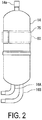
FIG. 2 is a front view illustrating an accumulator included in the rotary compressor inFIG. 1 . -
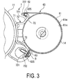
FIG. 3 is a plan view illustrating the vicinity of the accumulator of the rotary compressor inFIG. 1 . -
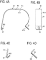
FIGS. 4A to 4D illustrate a bail strap used for affixing the accumulator to the rotary compressor inFIG. 1 .FIG. 4A is a side view of the bail strap, andFIG. 4B a front view.FIG. 4C is an enlarged view illustrating an engagement connection end inFIG. 4A. FIG. 4D is an enlarged view illustrating a fastening connection end inFIG. 4A . -
FIGS. 5A to 5C are views from three sides illustrating a bracket used for affixing the accumulator to the rotary compressor inFIG. 1 .FIG. 5A is a front view of the bracket,FIG. 5B a side view, andFIG. 5C a plan view. -
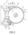
FIG. 6 is a plan view illustrating the vicinity of an accumulator of a rotary compressor according to a second embodiment of the present invention. -
FIG. 7A is a partially enlarged view ofFIG. 6 . -
FIG. 7B illustrates a method for configuring a vibration damping structure. -
FIG. 8 is a plan view illustrating the vicinity of an accumulator of a rotary compressor according to a variation of the second embodiment. -
FIGS. 9A and 9B illustrate the vicinity of an accumulator of a rotary compressor according to a third embodiment of the present invention.FIG. 9A is an exploded view of components.FIG. 9B illustrates the components assembled in predetermined positions. -
FIG. 10 is a cross-sectional view illustrating a conventional rotary compressor. - The present invention will be described below in detail on the basis of embodiments illustrated in the attached drawings.
- A
rotary compressor 1 according to a first embodiment of the present invention will now be described. - The
compressor 1 uses a bail strap (holding band) 60 being a metal band to affix an accumulator (auxiliary machine) 14 to a sealedcontainer 11 and has a structure to reduce the propagation of vibration from the sealedcontainer 11 to theaccumulator 14 via thebail strap 60. - A configuration of the
compressor 1 will be described below, and then, effects and benefits of thecompressor 1 will be described. - As illustrated in
FIG. 1 , thecompressor 1 is a so-called two-cylinder type rotary compressor in which disc-shapedcylinders container 11. - A cylindrical cylinder
internal wall surface 20S is formed on the interior of each of thecylinders Cylindrical piston rotors cylinders piston rotors internal wall surface 20S. Thepiston rotors eccentric shaft portions main shaft 23 that is arranged along the central axis C of the sealedcontainer 11. In this way, spaces R having a crescent-shaped cross-section are respectively formed between the cylinder internal wall surfaces 20S of thecylinders piston rotors - Here, the upper
side piston rotor 21A and the lowerside piston rotor 21B are provided so that a phase between them differs by 180°. - Furthermore, a disc-shaped
partition plate 24 is provided between the upper andlower cylinders partition plate 24, the space R inside theupper side cylinder 20A and the space R of thelower side cylinder 20B do not communicate with each other, and are partitioned into a compression chamber R1 and a compression chamber R2. - Blades (not illustrated in the drawings) that divide each of the compression chambers R1 and R2 into two sections are provided in the upper and
lower cylinders cylinders piston rotors - Furthermore, a discharge hole (not illustrated in the drawings) that discharges a refrigerant is provided in a predetermined position in each of the
cylinders cylinders - As illustrated in
FIG. 1 , themain shaft 23 is supported by anupper bearing 29A that is affixed to thecylinder 20A and alower bearing 29B that is affixed to thecylinder 20B, so that themain shaft 23 can freely rotate about its central axis. - The
main shaft 23 is provided with theeccentric shaft portions main shaft 23. Each of theeccentric shaft portions piston rotors main shaft 23 rotating, theeccentric shaft portions main shaft 23 and the upper andlower piston rotors cylinders piston rotors piston rotors - The
main shaft 23 protrudes upward from theupper bearing 29A, and arotor 37 of an electric motor (vibration source) 36 for rotary driving of themain shaft 23 is integrally provided with the protruding section of themain shaft 23. Astator 38 is affixed to the inner peripheral surface of the sealedcontainer 11 in correspondence with therotor 37. - The
upper bearing 29A is provided with a discharge hole (not illustrated in the drawings) that communicates with the discharge hole formed in thecylinder 20A, and the refrigerant that has passed through thecylinder 20A passes through the discharge hole in theupper bearing 29A and is discharged to the interior of amuffler 45A that will be described below. Similarly, thelower bearing 29B is provided with a discharge hole (not illustrated in the drawings) that communicates with the discharge hole formed in thecylinder 20B, and the refrigerant that has passed through thecylinder 20B passes through the discharge hole in thelower bearing 29B and is discharged to the interior of amuffler 45B that will be described below. - As illustrated in
FIG. 1 , in thecompressor 1, themuffler 45A is mounted on theupper bearing 29A, and themuffler 45B is mounted on thelower bearing 29B. Upon the refrigerant that has passed through theupper bearing 29A and thelower bearing 29B flowing into the interior of themuffler 45A and themuffler 45B, respectively, a pulsating component is removed. The refrigerant from which the pulsating component has been removed passes through a discharge channel formed in themuffler 45A and themuffler 45B, and flows toward the upper part of the sealedcontainer 11. -
Openings container 11, in positions facing outer peripheral surfaces of thecylinders Intake ports internal wall surfaces 20S are formed in thecylinders openings - As illustrated in
FIG. 1 , in thecompressor 1, theaccumulator 14 that performs gas-liquid separation on the refrigerant before the refrigerant is supplied to thecompressor 1 is affixed to the sealedcontainer 11 via anattachment structure 50. -
Intake pipes accumulator 14, for causing the refrigerant inside theaccumulator 14 to be sucked into thecompressor 1. The tip portions of theintake pipes intake ports openings - The
compressor 1 takes up the refrigerant into theaccumulator 14 from anintake tube 14a of theaccumulator 14, performs gas-liquid separation on the refrigerant inside theaccumulator 14, and supplies the resulting gas phase from theintake pipes cylinders intake ports cylinders - Then, the volume of the compression chambers R1 and R2 is gradually decreased by the rotation of the
piston rotors cylinder upper bearing 29A and themuffler 45A on thecylinder 20A side and passes through thelower bearing 29B and themuffler 45B on thecylinder 20B side, and is discharged into the interior of the sealed container 11 (the outside of themuffler 45A and themuffler 45B). After passing through theelectric motor 36, the refrigerant is evacuated to a pipe that forms a refrigerant cycle, via adischarge tube 42 that is provided in an upper portion. - The
accumulator 14 is attached to the sealedcontainer 11 of thecompressor 1 via theintake pipes accumulator 14 and the sealedcontainer 11 are also affixed to each other through theattachment structure 50. - As illustrated in
FIG. 1 , theattachment structure 50 includes thebail strap 60 wound around theaccumulator 14, abracket 70 affixed to the sealedcontainer 11, and abuffer material 75 made of a sheet rubber and disposed between thebail strap 60 and the sealedcontainer 11. - As illustrated in
FIGS. 3 ,4A, 4B, 4C, and 4D , thebail strap 60 includes an engagement connection end (first connection end) 62 formed by bending one end into a U-shape, a fastening connection end (second connection end) 63 formed by bending the other end into an L-shape, and afastening portion 61 extending between theengagement connection end 62 and thefastening connection end 63. Theengagement connection end 62 is inserted into an engagement groove 723 (FIGS. 5A and 5B ) provided in thebracket 70 to affix the one end of thebail strap 60 to thebracket 70. Furthermore, thefastening connection end 63 is fastened to thebracket 70 with a bolt B to affix the other end of thebail strap 60 to thebracket 70. A bolt hole 64 (FIG. 4B ) for passing the bolt B therethrough is formed in thefastening connection end 63. When theengagement connection end 62 and thefastening connection end 63 are affixed to thebracket 70, the securingportion 61 is wound around theaccumulator 14 and secures theaccumulator 14. - The
bail strap 60 is manufactured through sheet-metal processing in which a metal plate is subjected to punching and bending to have a shape illustrated inFIGS. 3 ,4A, 4B, 4C, and 4D . Thebracket 70 is manufactured in a similar manner. - The
bail strap 60 is provided with abuffer layer 62S and abuffer layer 63S at theengagement connection end 62 and thefastening connection end 63, respectively. Thebuffer layer 62S and thebuffer layer 63S may be formed by pasting a buffer material sheet composed of a buffer material made of, for example, natural or synthetic rubber, or synthetic resin. Alternatively, the layers may be formed by applying an adhesive gel and then curing the gel. - The
buffer layer 62S of theengagement connection end 62 is disposed on an innerperipheral surface 60IS of thebail strap 60. When theengagement connection end 62 is inserted into theengagement groove 723 of thebracket 70 and engaged with theengagement connection part 72, thebuffer layer 62S is positioned between theengagement connection end 62 and thebracket 70 to prevent contact between the metals, which will be described in detail later. - The
buffer layer 63S of thefastening connection end 63 is disposed on the innerperipheral surface 60IS of thebail strap 60. When thefastening connection end 63 is fastened to thebracket 70 with the bolt B, thebuffer layer 63S is positioned between thefastening connection end 63 and thebracket 70 to prevent contact between the metals, which will be described in detail later. - As illustrated in
FIGS. 3 ,5A, 5B, and 5C , thebracket 70 includes a weld-bondedportion 71 to be affixed to the sealedcontainer 11, and the engagement connection part (first connection part) 72 and a fastening connection part (second connection part) 73 respectively provided at tip ends offlanges portion 71 used for affixing thebail strap 60. - The
bracket 70 is arranged in a predetermined position and then bonded and affixed to the sealedcontainer 11 by welding the weld-bondedportion 71. - The weld-bonded
portion 71 has a similar cross section to that of a steel channel and includes aweb 711 and theflanges web 711. Theweb 711 is curved so as to have a curvature equivalent to that of the outer peripheral surface of the sealedcontainer 11 and is provided with a pair of positioningprotrusions surface 712 to be bonded to the sealedcontainer 11 with a space therebetween and are used for positioning with respect to the sealedcontainer 11. The positioningprotrusions container 11 to position thebracket 70. - The
engagement connection part 72 and thefastening connection part 73 are each formed to have a substantially L-shaped cross section and respectively correspond to theengagement connection end 62 and the fastening connection end 63 of thebail strap 60. - The
engagement connection part 72 includes a first supportingportion 721 and anengagement portion 722 formed by bending the tip end of the first supportingportion 721. The first supportingportion 721 comes into contact with theaccumulator 14 and supports theaccumulator 14. The surface in contact with theaccumulator 14 has a curvature equivalent to that of the outer peripheral surface of theaccumulator 14. Similarly, a second supportingportion 731 of thefastening connection part 73 comes into contact with theaccumulator 14 and supports theaccumulator 14. The surface in contact with theaccumulator 14 has a curvature equivalent to that of the outer peripheral surface of theaccumulator 14. Theengagement groove 723 for engagement with theengagement connection end 62 of thebail strap 60 is formed in theengagement portion 722. - The
fastening connection part 73 includes the second supportingportion 731 and afastening portion 732 formed by bending the tip end of the second supportingportion 731. Theflat fastening portion 732 supports thefastening connection end 63, laminated thereon, of thebail strap 60 and fastens and affixes thefastening connection end 63 by fastening the bolt B.A screw hole 733 through which the bolt B passes and that has a female thread formed thereon for engagement with the male thread of the bolt B is formed in thefastening portion 732. - The
flanges 714, the first supportingportion 721, and the second supportingportion 731 of thebracket 70 are elastic, and their elastic deformation converts vibration energy into thermal energy, resulting in a reduction in the propagation of vibration. - As illustrated in
FIGS. 1 and2 , thebuffer material 75 is composed of a rubber sheet and wound around theaccumulator 14. Thebuffer material 75 is disposed between theaccumulator 14 and thebail strap 60 to reduce the propagation of vibration from thebail strap 60 to theaccumulator 14. - The
buffer material 75 surrounds the outer peripheral surface of theaccumulator 14 by almost one round and is held between theaccumulator 14 and thebail strap 60 by thebail strap 60 securing thebuffer material 75 on its periphery. - The
accumulator 14 is attached to the sealedcontainer 11 with theattachment structure 50 including the above-describedbail strap 60,bracket 70, andbuffer material 75. In specific, the outer peripheral surface of theaccumulator 14 is brought into contact with the first supportingportion 721 and the second supportingportion 731 of thebracket 70 weld-bonded in a predetermined position of the sealedcontainer 11 as illustrated inFIGS. 1 to 3 . In this state, theengagement connection end 62 of thebail strap 60 is fitted into theengagement groove 723 formed in theengagement portion 722 of theengagement connection part 72 of thebracket 70 to engage theengagement connection end 62 with theengagement connection part 72. The fastening connection end 63 of thebail strap 60 is then overlapped on thefastening portion 732 of thefastening connection part 73 of thebracket 70. Consequently, the securingportion 61 of thebail strap 60 covers the periphery of theaccumulator 14. Then, the bolt B with its screw portion having passed through thebolt hole 64 is screwed into thescrew hole 733 of thefastening portion 732. The bolt B is screwed until its head portion reaches thefastening portion 732 and required securing force is yielded. This completes the attachment of theaccumulator 14. - An effect of the
compressor 1 will now be described. The effect relates to a reduction in the propagation of vibration generated by driving of theelectric motor 36 in the main body of thecompressor 1 including the sealedcontainer 11, to theaccumulator 14. - As illustrated in
FIGS. 3 ,4A, 4B, 4C, and 4D , in the present embodiment, thebuffer layer 62S is provided at theengagement connection end 62 of thebail strap 60 and positioned between theengagement connection end 62 and theengagement portion 722 of thebracket 70. Furthermore, thebuffer layer 63S is provided at the fastening connection end 63 of thebail strap 60 and positioned between thefastening connection end 63 and thefastening portion 732 of thebracket 70. The buffer layers 62S and 63S positioned between thebail strap 60 and thebracket 70 decrease the transmissibility of vibration generated in the sealedcontainer 11, from thebracket 70 to thebail strap 60, resulting in a reduction in vibration of theaccumulator 14. - Next, a
compressor 2 according to a second embodiment of the present invention will be described with reference toFIGS. 6 ,7A, and 7B . - The
compressor 2 has the same basic configuration as thecompressor 1, and the same components inFIGS. 6 to 8 have the same reference characters used for thecompressor 1. Features, differing from thecompressor 1, of thecompressor 2 will be mainly described below. - As illustrated in
FIGS. 6 ,7A, and 7B , thecompressor 2 includes avibration damping structure 65 in thebail strap 60. Thevibration damping structure 65 is disposed in a free region F that is on the side provided with theengagement connection end 62 of thebail strap 60 and does not come into contact with theaccumulator 14 and thebracket 70 so as not to have direct mechanical constraints. Here, it is assumed that thevibration damping structure 65 extends in the entire free region F in the width direction W (SeeFIG. 4B ) of thebail strap 60. Alternatively, thevibration damping structure 65 may extend only in a partial region in the width direction W. - The
vibration damping structure 65 has a similar structure to that of a laminated damping steel sheet. - A laminated damping steel sheet has a structure in which a viscoelastic resin layer having a thickness of approximately several tens µm is disposed between two steel sheets, and shear deformation of the viscoelastic resin layer due to bending vibration converts vibration energy into thermal energy to yield vibration damping effects.
- The
vibration damping structure 65 is composed of aviscoelastic resin layer 67 and asteel sheet 68 with thebail strap 60 functioning as one of the two steel sheets. In other words, thevibration damping structure 65 has a laminated structure in which theviscoelastic resin layer 67 is disposed between thebail strap 60 and thesteel sheet 68. - As illustrated in
FIG. 7B , thevibration damping structure 65 is obtained by laminating theviscoelastic resin layer 67 and thesteel sheet 68 to prepare a vibration damping structurepreparatory body 66 and pasting theviscoelastic resin layer 67 side on thebail strap 60. - Here, the
vibration damping structure 65 disposed on the outerperipheral surface 60os of thebail strap 60 is exemplified. Alternatively, thevibration damping structure 65 may be disposed on the innerperipheral surface 60IS or on both of the outerperipheral surface 60OS and the innerperipheral surface 60IS. - In the present embodiment, the
vibration damping structure 65 is disposed in the free region F. Consequently, even when vibration is transmitted from thebracket 70, shear deformation of theviscoelastic resin layer 67 of thevibration damping structure 65 damps vibration in the free region F. The propagation of vibration to theaccumulator 14 can thus be reduced. - In the present embodiment, the
vibration damping structure 65 disposed only in the free region F is exemplified. Alternatively, thevibration damping structure 65 may be disposed in a region other than the free region F. However, since shear deformation of theviscoelastic resin layer 67 provides the vibration damping effects of thevibration damping structure 65, thevibration damping structure 65 is preferably disposed in a section selected for yielding the effects and benefits. Furthermore, thevibration damping structure 65 may be disposed not only on thebail strap 60 but also on thebracket 70 side. - The vibration damping effects of the
vibration damping structure 65 can be more effectively yielded by expanding the free region F and disposing thevibration damping structure 65 in the free region F.FIG. 8 illustrates an example in which thevibration damping structure 65 is disposed on the basis of this viewpoint. - In a
compressor 1 inFIG. 8 , both ends of thebail strap 60 and thebracket 70 are affixed by engagement, such that the free region F can be expanded twice as large as the example inFIG. 6 . Consequently, the vibration damping effects can be doubled by disposing thevibration damping structure 65 in each of the free regions F. - The second embodiment illustrated in
FIGS. 6 to 8 exemplifies a configuration without the buffer layers 62S and 63S in the first embodiment; however, the buffer layers 62S and 63S in the first embodiment may be applied to the second embodiment. - Next, a
compressor 3 according to a third embodiment of the present invention will be described with reference toFIGS. 9A and 9B . - The
compressor 3 has the same basic configuration as thecompressors FIGS. 9A and 9B have the same reference characters used for thecompressors compressors compressor 3 will be mainly described below. - As illustrated in
FIGS. 9A and 9B , thecompressor 3 has a structure in which abracket 70 is bonded to theaccumulator 14 and abail strap 60 is wound around the sealedcontainer 11. - The
bail strap 60 and thebracket 70 follow the configuration of the second embodiment. Thebail strap 60 includes two engagement connection ends 62 on both ends thereof, and thebracket 70 includes twoengagement connection parts 72 on both ends thereof. - In the
bracket 70, a weld-bondedportion 71 is affixed to theaccumulator 14 by welding. In thebail strap 60, a securing portion 61 (not illustrated in the drawings) is wound around the sealedcontainer 11, and the engagement connection ends 62 and 62 are respectively engaged with theengagement connection parts bracket 70 to affix theaccumulator 14 to the sealedcontainer 11. - The
compressor 3 according to the third embodiment does not have constraints on the height position of attaching thebracket 70 by welding, which will be described below, and thus achieves such an effect that theattachment structure 50 can be disposed in a position selected so that vibration from the sealedcontainer 11 is the less liable to propagate to theaccumulator 14. - As illustrated in
FIG. 1 , the sealedcontainer 11 houses theelectric motor 36 therein and also functions as the case of theelectric motor 36. The sealedcontainer 11 is thus required to have a high roundness especially at a section housing theelectric motor 36 to ensure stable rotation of therotor 37. Since welding of thebracket 70 to the sealedcontainer 11 inevitably causes thermal strain in the sealedcontainer 11, thebracket 70 is welded in a region other than a region A housing theelectric motor 36 to prevent influences of the thermal strain on the region A in the first and second embodiments in which thebracket 70 is welded to the sealedcontainer 11. - Welding of the
bracket 70 to the sealedcontainer 11 has constraints on the height position of welding as described above. Unfortunately, the constraints on the welding position is undesirable in consideration of the propagation of vibration. That is, thestator 38 of the housedelectric motor 36 is fitted inside the sealedcontainer 11, such that the region A of the sealedcontainer 11 has high rigidity and readily reduces the amplitude of vibration. Therefore, when thebracket 70 is affixed in the region A, vibration from the sealedcontainer 11 is less liable to propagate to thebracket 70. - For this reason, the
bracket 70 is welded to theaccumulator 14, which is not adversely affected by thermal strain by welding, in the present embodiment. This configuration enables thebracket 70 to be affixed by welding in a position selected in a wide region B including the region A illustrated inFIG. 1 to readily reduce the amplitude of vibration. Thermal strain by welding is not generated in the sealedcontainer 11, and stable rotation of theelectric motor 36 is thus ensured. - Furthermore, the
compressor 3 according to the third embodiment also achieves such an effect that the magnitude of exciting force input to thebracket 70 is reduced by winding thebail strap 60 around the sealedcontainer 11, which will be described below. - It is understood that vibration of the sealed
container 11 generates exciting force F (F1, F2, F3, and F4) to the outside approximately in the positions indicated inFIG. 9B . When the exciting force F1, F2, F3, and F4 overlaps and generates greater exciting force, vibration propagated via thebracket 70 to theaccumulator 14 increases. It is thus required to prevent the exciting force F1, F2, F3, and F4 from overlapping to reduce vibration of theaccumulator 14. The present embodiment has the configuration in which thebracket 70 is affixed to theaccumulator 14 by welding and thebail strap 60 is wound around the sealedcontainer 11 having a larger diameter than that of theaccumulator 14, and a distance between F1 and F2 and a distance between F3 and F4 can thus be increased, resulting in a reduction of overlapping exciting force. - In the present embodiment, the sealed
container 11, around which thebail strap 60 is wound, has a larger external diameter than that of theaccumulator 14. The distance D between the positions in which the exciting force F1 and the exciting force F2 are generated and the distance D between the positions in which the exciting force F3 and the exciting force F4 are generated can thus be increased in comparison with the case in which thebail strap 60 is wound around theaccumulator 14. The increase in the distances between the exciting force F (F1, F2, F3, and F4) to disperse the force enables input of the exciting force to thebracket 70 with the phase of the exciting force differing from each other, resulting in a prevention of overlapping exciting force. - The third embodiment illustrated in
FIG. 9 exemplifies a configuration without the buffer layers 62S and 63S in the first embodiment and thevibration damping structure 65 in the second embodiment; however, the buffer layers 62S and 63S in the first embodiment and thevibration damping structure 65 in the second embodiment may be applied to the third embodiment. - The present invention has been described with reference to the first, second, and third embodiments. However, as long as there is no departure from the spirit and scope of the present invention, configurations described in the above embodiments can be selected as desired, or can be changed to other configurations as necessary.
- The above embodiments exemplify the electric motor of the rotary compressor being a vibration source and the accumulator being an auxiliary machine associated with the vibration source; however, these should not be construed to limit the present invention. The present invention can be widely applied to a combination of a vibration source other than a rotary compressor and an auxiliary machine other than an accumulator.
- Furthermore, if the present invention is applied to a rotary compressor, its specific configuration should not be limited to those described in the embodiments. The present invention can be widely applied to a rotary compressor including a rotary compressing mechanism, a sealed container, and an accumulator.
-
- 1, 2, 3
- Compressor
- 11
- Sealed container
- 12A
- Opening
- 12B
- Opening
- 14
- Accumulator (Auxiliary machine)
- 14a
- Intake tube
- 16A
- Intake pipe
- 16B
- Intake pipe
- 20A
- Cylinder
- 20B
- Cylinder
- 20S
- Cylinder internal wall surface
- 21A
- Piston rotor
- 21B
- Piston rotor
- 23
- Main shaft
- 24
- Partition plate
- 29A
- Upper bearing
- 29B
- Lower bearing
- 30A
- Intake port
- 30B
- Intake port
- 36
- Electric motor (Vibration source)
- 37
- Rotor
- 38
- Stator
- 40A
- Eccentric shaft portion
- 40B
- Eccentric shaft portion
- 42
- Discharge tube
- 45A
- Muffler
- 45B
- Muffler
- 50
- Attachment structure
- 60
- Bail strap (Holding band)
- 60IS
- Inner peripheral surface
- 60OS
- Outer peripheral surface
- 61
- Securing portion
- 62
- Engagement connection end (First connection end)
- 62S
- Buffer layer
- 63
- Fastening connection end (Second connection end)
- 63S
- Buffer layer
- 64
- Bolt hole
- 65
- Vibration damping structure
- 66
- Vibration damping structure preparatory body
- 67
- Viscoelastic resin layer
- 68
- Steel sheet
- 70
- Bracket
- 71
- Weld-bonded portion
- 72
- Engagement connection part (First connection part)
- 73
- Fastening connection part (Second connection part)
- 75
- Buffer material
- 711
- Web
- 712
- Bonded surface
- 713
- Positioning protrusion
- 714
- Flange
- 721
- First supporting portion
- 722
- Engagement portion
- 723
- Engagement groove
- 731
- Second supporting portion
- 732
- Fastening portion
- 733
- Screw hole
- B
- Bolt
- C
- Central axis
- R
- Space
- R1
- Compression chamber
- R2
- Compression chamber
Claims (8)
- An attachment structure for attaching an auxiliary machine to a container housing a vibration source therein by an attachment implement;
the attachment implement comprising:a holding band surrounding and holding a periphery of any one of the container and the auxiliary machine and including a first connection end and a second connection end; anda bracket affixed to other one of the container and the auxiliary machine and including a first connection part connected to the first connection end of the holding band and a second connection part connected to the second connection end of the holding band; andthe attachment implement comprising:a buffer layer disposed between connecting sections of the holding band and the bracket; ora vibration damping structure disposed in a free region of the holding band. - The attachment structure according to claim 1, wherein a buffer material sheet is disposed between the holding band and any one of the container and the auxiliary machine.
- The attachment structure according to claim 1 or 2, wherein the attachment implement, when comprising the buffer layer, comprises a vibration damping structure in a free region of the holding band.
- The attachment structure according to any one of claims 1 to 3, wherein:engagement is performed to connect the first connection end of the holding band with the first connection part of the bracket and to connect the second connection end of the holding band with the second connection part of the bracket; andthe vibration damping structure is disposed in the free region facing each of the first connection end and the second connection end.
- The attachment structure according to any one of claims 1 to 4, wherein:the vibration source is an electric motor; andwhen weld-bonding the bracket, the bracket is bonded to the auxiliary machine.
- An attachment structure for attaching an auxiliary machine to a container housing an electric motor being a vibration source therein by an attachment implement;
the attachment implement comprising:a holding band surrounding and holding a periphery of the container and including a first connection end and a second connection end; anda bracket affixed to the auxiliary machine by welding and including a first connection part connected to the first connection end of the holding band and a second connection part connected to the second connection end of the holding band. - An electric compressor, comprising the attachment implement according to any one of claims 1 to 5.
- An electric compressor, comprising the attachment implement according to claim 6.
Applications Claiming Priority (2)
| Application Number | Priority Date | Filing Date | Title |
|---|---|---|---|
| JP2014141977A JP6408808B2 (en) | 2014-07-10 | 2014-07-10 | Electric compressor |
| PCT/JP2015/003029 WO2016006167A1 (en) | 2014-07-10 | 2015-06-17 | Attachment structure, and electric compressor |
Publications (2)
| Publication Number | Publication Date |
|---|---|
| EP3168475A1 true EP3168475A1 (en) | 2017-05-17 |
| EP3168475A4 EP3168475A4 (en) | 2017-12-27 |
Family
ID=55063825
Family Applications (1)
| Application Number | Title | Priority Date | Filing Date |
|---|---|---|---|
| EP15819766.5A Withdrawn EP3168475A4 (en) | 2014-07-10 | 2015-06-17 | Attachment structure, and electric compressor |
Country Status (4)
| Country | Link |
|---|---|
| EP (1) | EP3168475A4 (en) |
| JP (1) | JP6408808B2 (en) |
| CN (1) | CN106415007B (en) |
| WO (1) | WO2016006167A1 (en) |
Cited By (3)
| Publication number | Priority date | Publication date | Assignee | Title |
|---|---|---|---|---|
| EP3567250A1 (en) * | 2018-05-11 | 2019-11-13 | Mitsubishi Heavy Industries Thermal Systems, Ltd. | Compressor system |
| US12209781B2 (en) | 2020-01-30 | 2025-01-28 | Fujitsu General Limited | Rotary compressor |
| EP4603704A3 (en) * | 2024-02-14 | 2025-09-24 | Carrier Japan Corporation | Accumulator fixing mechanism and compressor |
Families Citing this family (4)
| Publication number | Priority date | Publication date | Assignee | Title |
|---|---|---|---|---|
| JP6611907B2 (en) * | 2016-03-08 | 2019-11-27 | 三菱電機株式会社 | Gas-liquid separator fixture, hermetic compressor, hermetic compressor manufacturing apparatus, and hermetic compressor manufacturing method |
| CN107588004B (en) * | 2017-08-28 | 2023-08-25 | 珠海格力节能环保制冷技术研究中心有限公司 | Support frame structure and compressor with same |
| CN112727772A (en) * | 2021-01-25 | 2021-04-30 | 珠海格力节能环保制冷技术研究中心有限公司 | Compressor |
| JP7143496B1 (en) * | 2021-09-30 | 2022-09-28 | ダイキン工業株式会社 | compressor unit |
Family Cites Families (20)
| Publication number | Priority date | Publication date | Assignee | Title |
|---|---|---|---|---|
| JPS57120775U (en) * | 1981-01-20 | 1982-07-27 | ||
| JPS5950244A (en) * | 1982-09-17 | 1984-03-23 | Matsushita Electric Ind Co Ltd | Vibration damping device for rotary electric compressor |
| JPS6065289A (en) * | 1983-09-19 | 1985-04-15 | Matsushita Electric Ind Co Ltd | Accumulator fixing device for hermetic compressor |
| JPS6181826A (en) * | 1984-09-27 | 1986-04-25 | Honda Motor Co Ltd | Clutch control system vibration isolator |
| JPS62176U (en) * | 1985-06-18 | 1987-01-06 | ||
| JPH09137789A (en) * | 1995-11-14 | 1997-05-27 | Sanyo Electric Co Ltd | Hermetic type rotary compressor |
| CN2431112Y (en) * | 2000-06-01 | 2001-05-23 | 朱金龙 | Composite metal damping plate |
| JP2002147530A (en) * | 2000-11-15 | 2002-05-22 | Honda Motor Co Ltd | Anti-vibration device |
| JP2003136948A (en) * | 2001-11-06 | 2003-05-14 | Nippon Soken Inc | Mounting device for vertical electric compressor |
| JP4017561B2 (en) * | 2003-06-02 | 2007-12-05 | イワブチ株式会社 | Device for supporting the vertical part of armrests for equipment columns made of cylinders |
| CN1580567A (en) * | 2003-07-30 | 2005-02-16 | 乐金电子(天津)电器有限公司 | Fixing device of compressor liquid-storage cylinder |
| CN2811878Y (en) * | 2005-07-29 | 2006-08-30 | 乐金电子(天津)电器有限公司 | Fixing support for liquid storage tank |
| JP2008292062A (en) * | 2007-05-24 | 2008-12-04 | Sharp Corp | Refrigerant container fixing device for compressor piping |
| JP2009162222A (en) * | 2007-12-14 | 2009-07-23 | Daikin Ind Ltd | Hermetic compressor |
| CN101684808A (en) * | 2008-09-27 | 2010-03-31 | 乐金电子(天津)电器有限公司 | Enclosed type compressor |
| KR101248660B1 (en) * | 2009-04-23 | 2013-03-28 | 카야바 고교 가부시기가이샤 | Pipe securing structure for cylinder tube |
| JP5482387B2 (en) * | 2010-03-31 | 2014-05-07 | 株式会社豊田自動織機 | Electric compressor |
| CN202117930U (en) * | 2011-05-03 | 2012-01-18 | 广东美芝制冷设备有限公司 | Bent pipe vibration-reducing structure of variable volume rotary compressor |
| JP5899838B2 (en) * | 2011-11-11 | 2016-04-06 | ダイキン工業株式会社 | Compressor unit |
| JP6020148B2 (en) * | 2012-03-20 | 2016-11-02 | 株式会社豊田自動織機 | Electric compressor |
-
2014
- 2014-07-10 JP JP2014141977A patent/JP6408808B2/en active Active
-
2015
- 2015-06-17 WO PCT/JP2015/003029 patent/WO2016006167A1/en not_active Ceased
- 2015-06-17 EP EP15819766.5A patent/EP3168475A4/en not_active Withdrawn
- 2015-06-17 CN CN201580029267.6A patent/CN106415007B/en active Active
Cited By (3)
| Publication number | Priority date | Publication date | Assignee | Title |
|---|---|---|---|---|
| EP3567250A1 (en) * | 2018-05-11 | 2019-11-13 | Mitsubishi Heavy Industries Thermal Systems, Ltd. | Compressor system |
| US12209781B2 (en) | 2020-01-30 | 2025-01-28 | Fujitsu General Limited | Rotary compressor |
| EP4603704A3 (en) * | 2024-02-14 | 2025-09-24 | Carrier Japan Corporation | Accumulator fixing mechanism and compressor |
Also Published As
| Publication number | Publication date |
|---|---|
| CN106415007B (en) | 2019-11-01 |
| JP6408808B2 (en) | 2018-10-17 |
| EP3168475A4 (en) | 2017-12-27 |
| JP2016017492A (en) | 2016-02-01 |
| CN106415007A (en) | 2017-02-15 |
| WO2016006167A1 (en) | 2016-01-14 |
Similar Documents
| Publication | Publication Date | Title |
|---|---|---|
| JP5788305B2 (en) | Electric compressor | |
| JP6408808B2 (en) | Electric compressor | |
| EP3447296A1 (en) | Compressor | |
| KR101375979B1 (en) | Rotary compressor | |
| US8419380B2 (en) | Hermetic compressor | |
| EP2960507B1 (en) | Linear compressor, shell for linear compressor, and method for manufacturing shell of linear compressor | |
| CN105683576B (en) | Electric scroll compressor | |
| EP3173626A1 (en) | Bracket for compressor, and rotary compressor | |
| EP3369932B1 (en) | Rotary compressor | |
| CN105201839A (en) | Rotary compressor provided with outer rotor type motor | |
| KR101718037B1 (en) | Enclosed compressor | |
| JP6431421B2 (en) | Electric compressor | |
| US20060127260A1 (en) | Scroll compressor having frame fixing structure and frame fixing method thereof | |
| EP3147508B1 (en) | Sealed-type electric compressor | |
| WO2014141331A1 (en) | Rotary compressor | |
| KR102662655B1 (en) | Compressor | |
| JP5672855B2 (en) | Compressor | |
| JP6383335B2 (en) | Electric compressor | |
| EP3399193A1 (en) | Rotary compressor | |
| JP2016113923A (en) | Compressor | |
| JP2007016681A (en) | Rotary compressor | |
| JP2012246838A (en) | Compressor assembly | |
| JP2007016771A (en) | Rotary compressor | |
| KR20000016089U (en) | Structure combining shells in rotary compressor | |
| JP2007016772A (en) | Rotary compressor |
Legal Events
| Date | Code | Title | Description |
|---|---|---|---|
| PUAI | Public reference made under article 153(3) epc to a published international application that has entered the european phase |
Free format text: ORIGINAL CODE: 0009012 |
|
| 17P | Request for examination filed |
Effective date: 20161128 |
|
| AK | Designated contracting states |
Kind code of ref document: A1 Designated state(s): AL AT BE BG CH CY CZ DE DK EE ES FI FR GB GR HR HU IE IS IT LI LT LU LV MC MK MT NL NO PL PT RO RS SE SI SK SM TR |
|
| AX | Request for extension of the european patent |
Extension state: BA ME |
|
| DAV | Request for validation of the european patent (deleted) | ||
| DAX | Request for extension of the european patent (deleted) | ||
| A4 | Supplementary search report drawn up and despatched |
Effective date: 20171127 |
|
| RIC1 | Information provided on ipc code assigned before grant |
Ipc: F04B 39/00 20060101AFI20171121BHEP Ipc: F04B 39/12 20060101ALI20171121BHEP |
|
| RAP1 | Party data changed (applicant data changed or rights of an application transferred) |
Owner name: MITSUBISHI HEAVY INDUSTRIES THERMAL SYSTEMS, LTD. |
|
| STAA | Information on the status of an ep patent application or granted ep patent |
Free format text: STATUS: THE APPLICATION HAS BEEN WITHDRAWN |
|
| 18W | Application withdrawn |
Effective date: 20191001 |