EP3167233B1 - Mechanischer verbinder und rahmen für ein solarpaneel - Google Patents
Mechanischer verbinder und rahmen für ein solarpaneel Download PDFInfo
- Publication number
- EP3167233B1 EP3167233B1 EP15818553.8A EP15818553A EP3167233B1 EP 3167233 B1 EP3167233 B1 EP 3167233B1 EP 15818553 A EP15818553 A EP 15818553A EP 3167233 B1 EP3167233 B1 EP 3167233B1
- Authority
- EP
- European Patent Office
- Prior art keywords
- spacer
- clamp
- article
- manufacture
- solar panels
- Prior art date
- Legal status (The legal status is an assumption and is not a legal conclusion. Google has not performed a legal analysis and makes no representation as to the accuracy of the status listed.)
- Active
Links
Images


Classifications
-
- H—ELECTRICITY
- H02—GENERATION; CONVERSION OR DISTRIBUTION OF ELECTRIC POWER
- H02S—GENERATION OF ELECTRIC POWER BY CONVERSION OF INFRARED RADIATION, VISIBLE LIGHT OR ULTRAVIOLET LIGHT, e.g. USING PHOTOVOLTAIC [PV] MODULES
- H02S30/00—Structural details of PV modules other than those related to light conversion
- H02S30/10—Frame structures
-
- E—FIXED CONSTRUCTIONS
- E04—BUILDING
- E04H—BUILDINGS OR LIKE STRUCTURES FOR PARTICULAR PURPOSES; SWIMMING OR SPLASH BATHS OR POOLS; MASTS; FENCING; TENTS OR CANOPIES, IN GENERAL
- E04H14/00—Buildings for combinations of different purposes not covered by any single one of main groups E04H1/00-E04H13/00 of this subclass, e.g. for double purpose; Buildings of the drive-in type
-
- F—MECHANICAL ENGINEERING; LIGHTING; HEATING; WEAPONS; BLASTING
- F24—HEATING; RANGES; VENTILATING
- F24S—SOLAR HEAT COLLECTORS; SOLAR HEAT SYSTEMS
- F24S25/00—Arrangement of stationary mountings or supports for solar heat collector modules
- F24S25/60—Fixation means, e.g. fasteners, specially adapted for supporting solar heat collector modules
- F24S25/61—Fixation means, e.g. fasteners, specially adapted for supporting solar heat collector modules for fixing to the ground or to building structures
-
- F—MECHANICAL ENGINEERING; LIGHTING; HEATING; WEAPONS; BLASTING
- F24—HEATING; RANGES; VENTILATING
- F24S—SOLAR HEAT COLLECTORS; SOLAR HEAT SYSTEMS
- F24S25/00—Arrangement of stationary mountings or supports for solar heat collector modules
- F24S25/60—Fixation means, e.g. fasteners, specially adapted for supporting solar heat collector modules
- F24S25/63—Fixation means, e.g. fasteners, specially adapted for supporting solar heat collector modules for fixing modules or their peripheral frames to supporting elements
- F24S25/632—Side connectors; Base connectors
-
- H—ELECTRICITY
- H02—GENERATION; CONVERSION OR DISTRIBUTION OF ELECTRIC POWER
- H02S—GENERATION OF ELECTRIC POWER BY CONVERSION OF INFRARED RADIATION, VISIBLE LIGHT OR ULTRAVIOLET LIGHT, e.g. USING PHOTOVOLTAIC [PV] MODULES
- H02S20/00—Supporting structures for PV modules
- H02S20/20—Supporting structures directly fixed to an immovable object
- H02S20/22—Supporting structures directly fixed to an immovable object specially adapted for buildings
- H02S20/23—Supporting structures directly fixed to an immovable object specially adapted for buildings specially adapted for roof structures
-
- H—ELECTRICITY
- H10—SEMICONDUCTOR DEVICES; ELECTRIC SOLID-STATE DEVICES NOT OTHERWISE PROVIDED FOR
- H10F—INORGANIC SEMICONDUCTOR DEVICES SENSITIVE TO INFRARED RADIATION, LIGHT, ELECTROMAGNETIC RADIATION OF SHORTER WAVELENGTH OR CORPUSCULAR RADIATION
- H10F19/00—Integrated devices, or assemblies of multiple devices, comprising at least one photovoltaic cell covered by group H10F10/00, e.g. photovoltaic modules
-
- F—MECHANICAL ENGINEERING; LIGHTING; HEATING; WEAPONS; BLASTING
- F16—ENGINEERING ELEMENTS AND UNITS; GENERAL MEASURES FOR PRODUCING AND MAINTAINING EFFECTIVE FUNCTIONING OF MACHINES OR INSTALLATIONS; THERMAL INSULATION IN GENERAL
- F16B—DEVICES FOR FASTENING OR SECURING CONSTRUCTIONAL ELEMENTS OR MACHINE PARTS TOGETHER, e.g. NAILS, BOLTS, CIRCLIPS, CLAMPS, CLIPS OR WEDGES; JOINTS OR JOINTING
- F16B5/00—Joining sheets or plates, e.g. panels, to one another or to strips or bars parallel to them
- F16B5/0004—Joining sheets, plates or panels in abutting relationship
- F16B5/0008—Joining sheets, plates or panels in abutting relationship by moving the sheets, plates or panels substantially in their own plane, perpendicular to the abutting edge
- F16B5/002—Joining sheets, plates or panels in abutting relationship by moving the sheets, plates or panels substantially in their own plane, perpendicular to the abutting edge both sheets, plates or panels having a groove, e.g. with strip-type connector
-
- F—MECHANICAL ENGINEERING; LIGHTING; HEATING; WEAPONS; BLASTING
- F16—ENGINEERING ELEMENTS AND UNITS; GENERAL MEASURES FOR PRODUCING AND MAINTAINING EFFECTIVE FUNCTIONING OF MACHINES OR INSTALLATIONS; THERMAL INSULATION IN GENERAL
- F16B—DEVICES FOR FASTENING OR SECURING CONSTRUCTIONAL ELEMENTS OR MACHINE PARTS TOGETHER, e.g. NAILS, BOLTS, CIRCLIPS, CLAMPS, CLIPS OR WEDGES; JOINTS OR JOINTING
- F16B5/00—Joining sheets or plates, e.g. panels, to one another or to strips or bars parallel to them
- F16B5/06—Joining sheets or plates, e.g. panels, to one another or to strips or bars parallel to them by means of clamps or clips
- F16B5/0607—Joining sheets or plates, e.g. panels, to one another or to strips or bars parallel to them by means of clamps or clips joining sheets or plates to each other
- F16B5/0614—Joining sheets or plates, e.g. panels, to one another or to strips or bars parallel to them by means of clamps or clips joining sheets or plates to each other in angled relationship
-
- F—MECHANICAL ENGINEERING; LIGHTING; HEATING; WEAPONS; BLASTING
- F24—HEATING; RANGES; VENTILATING
- F24S—SOLAR HEAT COLLECTORS; SOLAR HEAT SYSTEMS
- F24S25/00—Arrangement of stationary mountings or supports for solar heat collector modules
- F24S25/20—Peripheral frames for modules
-
- F—MECHANICAL ENGINEERING; LIGHTING; HEATING; WEAPONS; BLASTING
- F24—HEATING; RANGES; VENTILATING
- F24S—SOLAR HEAT COLLECTORS; SOLAR HEAT SYSTEMS
- F24S25/00—Arrangement of stationary mountings or supports for solar heat collector modules
- F24S25/30—Arrangement of stationary mountings or supports for solar heat collector modules using elongate rigid mounting elements extending substantially along the supporting surface, e.g. for covering buildings with solar heat collectors
- F24S25/33—Arrangement of stationary mountings or supports for solar heat collector modules using elongate rigid mounting elements extending substantially along the supporting surface, e.g. for covering buildings with solar heat collectors forming substantially planar assemblies, e.g. of coplanar or stacked profiles
-
- F—MECHANICAL ENGINEERING; LIGHTING; HEATING; WEAPONS; BLASTING
- F24—HEATING; RANGES; VENTILATING
- F24S—SOLAR HEAT COLLECTORS; SOLAR HEAT SYSTEMS
- F24S25/00—Arrangement of stationary mountings or supports for solar heat collector modules
- F24S25/60—Fixation means, e.g. fasteners, specially adapted for supporting solar heat collector modules
- F24S25/63—Fixation means, e.g. fasteners, specially adapted for supporting solar heat collector modules for fixing modules or their peripheral frames to supporting elements
- F24S25/634—Clamps; Clips
- F24S25/636—Clamps; Clips clamping by screw-threaded elements
-
- F—MECHANICAL ENGINEERING; LIGHTING; HEATING; WEAPONS; BLASTING
- F24—HEATING; RANGES; VENTILATING
- F24S—SOLAR HEAT COLLECTORS; SOLAR HEAT SYSTEMS
- F24S25/00—Arrangement of stationary mountings or supports for solar heat collector modules
- F24S25/60—Fixation means, e.g. fasteners, specially adapted for supporting solar heat collector modules
- F24S25/67—Fixation means, e.g. fasteners, specially adapted for supporting solar heat collector modules for coupling adjacent modules or their peripheral frames
-
- Y—GENERAL TAGGING OF NEW TECHNOLOGICAL DEVELOPMENTS; GENERAL TAGGING OF CROSS-SECTIONAL TECHNOLOGIES SPANNING OVER SEVERAL SECTIONS OF THE IPC; TECHNICAL SUBJECTS COVERED BY FORMER USPC CROSS-REFERENCE ART COLLECTIONS [XRACs] AND DIGESTS
- Y02—TECHNOLOGIES OR APPLICATIONS FOR MITIGATION OR ADAPTATION AGAINST CLIMATE CHANGE
- Y02B—CLIMATE CHANGE MITIGATION TECHNOLOGIES RELATED TO BUILDINGS, e.g. HOUSING, HOUSE APPLIANCES OR RELATED END-USER APPLICATIONS
- Y02B10/00—Integration of renewable energy sources in buildings
- Y02B10/10—Photovoltaic [PV]
-
- Y—GENERAL TAGGING OF NEW TECHNOLOGICAL DEVELOPMENTS; GENERAL TAGGING OF CROSS-SECTIONAL TECHNOLOGIES SPANNING OVER SEVERAL SECTIONS OF THE IPC; TECHNICAL SUBJECTS COVERED BY FORMER USPC CROSS-REFERENCE ART COLLECTIONS [XRACs] AND DIGESTS
- Y02—TECHNOLOGIES OR APPLICATIONS FOR MITIGATION OR ADAPTATION AGAINST CLIMATE CHANGE
- Y02B—CLIMATE CHANGE MITIGATION TECHNOLOGIES RELATED TO BUILDINGS, e.g. HOUSING, HOUSE APPLIANCES OR RELATED END-USER APPLICATIONS
- Y02B10/00—Integration of renewable energy sources in buildings
- Y02B10/20—Solar thermal
-
- Y—GENERAL TAGGING OF NEW TECHNOLOGICAL DEVELOPMENTS; GENERAL TAGGING OF CROSS-SECTIONAL TECHNOLOGIES SPANNING OVER SEVERAL SECTIONS OF THE IPC; TECHNICAL SUBJECTS COVERED BY FORMER USPC CROSS-REFERENCE ART COLLECTIONS [XRACs] AND DIGESTS
- Y02—TECHNOLOGIES OR APPLICATIONS FOR MITIGATION OR ADAPTATION AGAINST CLIMATE CHANGE
- Y02E—REDUCTION OF GREENHOUSE GAS [GHG] EMISSIONS, RELATED TO ENERGY GENERATION, TRANSMISSION OR DISTRIBUTION
- Y02E10/00—Energy generation through renewable energy sources
- Y02E10/40—Solar thermal energy, e.g. solar towers
- Y02E10/47—Mountings or tracking
-
- Y—GENERAL TAGGING OF NEW TECHNOLOGICAL DEVELOPMENTS; GENERAL TAGGING OF CROSS-SECTIONAL TECHNOLOGIES SPANNING OVER SEVERAL SECTIONS OF THE IPC; TECHNICAL SUBJECTS COVERED BY FORMER USPC CROSS-REFERENCE ART COLLECTIONS [XRACs] AND DIGESTS
- Y02—TECHNOLOGIES OR APPLICATIONS FOR MITIGATION OR ADAPTATION AGAINST CLIMATE CHANGE
- Y02E—REDUCTION OF GREENHOUSE GAS [GHG] EMISSIONS, RELATED TO ENERGY GENERATION, TRANSMISSION OR DISTRIBUTION
- Y02E10/00—Energy generation through renewable energy sources
- Y02E10/50—Photovoltaic [PV] energy
Definitions
- renewable energy sources which include hydroelectric, wind, solar, geothermal and biomass have been introduced as supplements to traditional energy sources in major business and industry sectors.
- solar powered energy sources have even become the primary energy source for some residences.
- solar power generation for residential establishments involve installing large solar panels on rooftops. These solar panels absorb the solar radiation and convert the absorbed energy into electricity, which can be used to power the residence.
- installation of these panels can be complex and/or difficult due to their size.
- a mounting system is first installed, and secured against specific locations (e.g., against rafters).
- a series of rails are then put in place in the mounting system (typically in a grid-like arrangement).
- the solar panels themselves are then securely affixed to the rails and, eventually, to neighboring panels via mechanical and/or electrical connectors.
- the railing system presents additional expenditures due to materials and transport costs of the rails themselves.
- solar panels were developed that were capable of being installed directly to mounting systems without the need for rails.
- the solar panels are mechanically affixed to each other (typically in series), using a mechanical connectors, sometimes implemented as cylindrical rods or trapezoidal beams.
- these connectors consist of rigid, threaded connectors, often positioned in short tunnels within the interiors of frames of two neighboring rectangular panels.
- the connectors are inserted into a first panel, and then to a second panel on the opposite end of the splice. Initially, the connectors protrude into each panel insecurely. Subsequently, the connectors may be manually tightened to both panels -- often in a user-intensive process -- which increases the rigidity of the connection.
- the connectors are generally very difficult to access while the panels are in position.
- the invention is defined in claim 1.
- an article of manufacture for use in a solar panel installation having at least first and second solar panels.
- Each solar panel may include a frame encircling a perimeter of the solar panel and a first channel disposed along a portion of the frame.
- the channel may be configured to affix the solar panel to one or more mounting points.
- a second channel may be disposed along one of an internal and external surface of the frame and be configured to retain a widened portion of a fastener positioned within the channel.
- the article may include an elongated body having a first end, and a second end opposite the first end, each of the respective first and second ends being shaped to match a configuration of the second channel and to be received and retained in the second channel of the respective first solar panel and the second solar panels.
- a spacer defines opposing surfaces for engaging the first and second solar panels and a slot.
- the elongated body is positioned within the slot.
- a clamp is secured to the spacer and defines first and second seats each configured to receive a lower portion of the frames of the first and second solar panels, respectively.
- the article of manufacture includes spacer defining opposing surfaces for engaging the first and second solar panels.
- the spacer further includes a first protuberance configured to insert into the first channel of the first solar panel and a second protuberance configured to insert into the first channel of the second solar panel.
- a flange extends between the first and second solar panels and is positioned to extend between the first and second solar panels when the first protuberance is inserted within the first channel.
- the flange further defines an aperture for receiving a fastener engaging one of the first channel and the second channel of one or more of the first and second solar panel.
- a clamp is secured to the spacer and defines first and second seats each configured to receive a lower portion of the frames of the first and second solar panels, respectively.
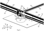
- solar panels such as solar panels secured to a rack in accordance with prior racking systems, may be coupled to one another without the use of a rack using the illustrated east-west bracket 100.
- Other solar panels may also be used with the illustrated coupler 100.
- the coupler 100 may be understood with respect to the illustrated directions including a vertical direction 102, a horizontal direction 104 perpendicular to the vertical direction 102, and a longitudinal direction perpendicular to the vertical and horizontal directions 102, 104.
- the vertical direction 102 may generally correspond to absolute vertical, i.e. the direction of action of gravity.
- the horizontal direction 104 may generally correspond to an east-to-west and west-to-east direction.
- the longitudinal direction may generally correspond to a north-to-south and south-to-north direction. In most applications in the northern hemisphere, solar panels are mounted on a south facing surface and arrayed in one or both of an east-west direction and a north-south direction.
- the east-west bracket 100 may include a spacer 108 defining lateral surfaces for engaging solar panels on either side of the spacer 108.
- surfaces of the spacer 108 offset from one another in the horizontal direction 104 may be parallel to one another and provide a flat or contoured surface for engaging a frame of a solar panel.
- the spacer 108 may define a slot 110 passing completely therethrough in the longitudinal direction and receiving a splice 112.
- the slot 110 may define a constant cross section in the horizontal direction 104 in order to facilitate sliding of the splice 112 through the slot.
- the splice 112 may be securable within the slot 110, such as by means of a screw, bolt, pin, or other fastener engaging the splice 112 and spacer 108.
- a lip 114 formed on the spacer engages the splice 112 and resists removal thereof unless moved by application of force.
- a clamp secures to the spacer 108, such as located below the slot 110 in the vertical direction 102. As shown the clamp 116 extends outwardly on either side of the spacer 108 in the horizontal direction 104.
- the clamp 116 may have a U-shaped or concave cross section defining a channel along some or all of the length thereof in the horizontal direction 104 and a portion of the spacer 108 may insert within this channel.
- the clamp 116 may secure to the spacer 108 by means of a bolt 118 passing through the spacer 108 and engaging the clamp.
- the bolt includes a head positioned above the spacer 108 in the vertical direction 102 and a threaded portion protruding below the spacer 108 in the vertical direction 102. The threaded portion may engage a threaded aperture in the clamp 116.
- a spring 120 positioned between the spacer and the head of the bolt 118 may urge the bolt 118 upwardly in vertical direction 102 and thereby urging the clamp 116 upward toward the spacer.
- the bolt 118 may insert through an aperture in the clamp 116 and threadably engage the spacer 108.
- the spring 120 may be inserted between the head of the bolt 118, or a nut threaded on the bolt 118, and the clamp 116 in order to urge the clamp 116 toward the spacer 108.
- other fastening means may also be used to secure the clamp 116 to the spacer 108, such as a screw, lynch pin, detent, or some other fastener.
- splice 112 may have some or all of the illustrated attributes.
- the splice 112 has a width in the horizontal direction 104 many times greater than dimension of the splice 112 in the vertical and longitudinal directions 102, 104.
- the width in the horizontal direction 104 may be between three and ten times, preferably between five and ten times greater than dimensions of the splice 112 in the vertical direction 102.
- the splice 112 may also be taller in the vertical direction 102 than it is deep in the longitudinal direction 106, such as between two and four times taller, in order to support stresses in a vertical plane (i.e., in the vertical and horizontal directions 102, 104).
- the splice 112 may define a notch 202, such as extending across a center of the splice 112 in the horizontal direction 104.
- a horizontal edge of the splice 112 may be beveled at an angle 204, e.g. between 40 and 60 degrees, such as 45 degrees in the illustrated embodiment.
- the angle 204 may correspond to an angle defined by the lip 114 and the lip 114 may seat within the notch 202 when the splice 112 is positioned within the slot 110.
- the lip 114 may define an angle 204 corresponding to the angle 204 of the notch 202 in order to seat within the notch 202 or may have a different angle 204.
- a spacer 108 may have the illustrated geometry.
- the slot 110 defined by the spacer 108 may define an upper slot surface 300 having a lip 302 extending downwardly from a distal end thereof and a lower slot surface 304 vertically below the upper slot surface 300 and having the lip 114 defined at a distal end thereof.
- the splice 112 is sized to insert freely into the slot 110 between the upper and lower surfaces 300, 304.
- the lips 302, 114 prevent removal of the splice 112 from the slot 110 in the longitudinal direction 106.
- the lower surface 306 may be defined on a flexible flange 306 that has a thickness and or material that permits flexing of the flange 306 without breaking.
- cutouts 308 within the body of the spacer 108 extend the length of the flange 306 beyond the interior wall 310 of the slot 110 in the longitudinal direction 106.
- the depth of the cutouts 308 beyond the interior wall 310 may be equal to or greater than the depth in the longitudinal direction of the slot 110 to the interior wall 310 as measured from the opening of the slot 110 (e.g. the leftmost surface of the spacer in Fig. 3 ).
- the geometry of the flange 306 may be defined by the force required to urge the lip 114 out of engagement with the notch 202 sufficient for the splice 112 to slide longitudinally within the slot 110, responsive to a longitudinal force exerted without the use of tools, such as a force of from three to five pounds.
- a longitudinal force exerted without the use of tools such as a force of from three to five pounds.
- the amount of vertical force required to be exerted on the flange 306 and deflect the flange 306 to achieve this slidability may require the use of a tool or may be performed manually.
- the amount of vertical force to achieve the above-noted longitudinal force required for sliding may be from two to ten pounds.
- Fig. 3 further illustrates an aperture 312 extending vertically through the spacer 108 for receiving the bolt 118.
- the aperture 312 may intersect the flange 306 or be horizontally offset therefrom.
- the aperture 312 defines a countersunk portion 314 at the upper end thereof and the spring 120 seats within the countersunk portion 314.
- the vertical depth of the countersunk portion 314 may be any depth needed to accommodate a given spring geometry as needed to provide a desired amount of clamping force by the clamp 116. For example, absent any extending force urging the clamp 116 away from the spacer 108, the force exerted on the clamp by the spring 120 may be from 0.5 to two pounds of force.
- Figs. 4A through 4C illustrate an example configuration for a clamp 116.
- the clamp 116 may define one or more seats 400a, 400b sized and shaped to receive a portion of a frame of a solar panel, such as the lower edge, a lateral surface, upper edge, or some other portion of a solar panel.
- a portion of a frame of a solar panel such as the lower edge, a lateral surface, upper edge, or some other portion of a solar panel.
- two seats 400a, 400b are shown that are positioned on either side of the spacer 108 (see Fig. 1 ).
- a single seat 400a may be used such that the presence of the spacer 108 maintains separation between solar panels, rather than the separation between separate seats 400a, 400b.
- the shape of the seats 400a, 400b may conform to geometry of the portion of the frame inserted therein.
- the seats 400a, 400b may be rectangular grooves extending in the longitudinal direction 306.
- indentations 402a, 402b in the corners of the seats 400a, 400b may accommodate corresponding ridges on a lower edge of a frame.
- a flange 404 is positioned horizontally between the seats 400a, 400b and sides of the flange 404 may be interior walls 406 of the seats 400a, 400b.
- the flange 404 may extend vertically upward between solar panels inserted within the seats 400a, 400b and maintains separation between the seats 400a, 400b.
- the horizontal width of the flange 404 may be greater than or smaller than the horizontal width of the spacer 108 such that either of the flange 404 and the body of the spacer 108 maintains separation between the solar panels positioned within the seats 400a, 400b.
- the clamp 116 may advantageously facilitate toolless engagement with a frame.
- sloped portions 408 may be positioned outward from the seats 400a, 400b in the horizontal direction 104. As shown the sloped portions 408 slope downward in the vertical direction 102 with distance from the center of the clamp 116. In this manner responsive to a horizontal force urging the east-west bracket against a frame, the sloped portions 408 guides the clamp 116 over the frame such that the frame can engage one of the seats 300a, 300b.
- the sloped portions 408 may extend from distal ends of the clamp 116 to an outer wall 410 of the seats 400a, 400b. As illustrated, transitions between the slopes portions 408 and the wall 410 may be rounded.
- the clamp 116 may include one or more scoring portions 412a, 412b positioned to contact portions of frames inserted within the seats 400a, 400b.
- the frames may be coated with paint, anodization, or some other coating. These coatings may be non-conductive. Accordingly, the scoring portions 412a, 412b may be positioned to penetrate these coatings when frames are positioned within the seats 400a, 400b. In this manner, the clamp 116 may establish an electrical grounding connection between panels secured to one another.
- the scoring portions 412a, 412b may be any sharpened structures that can readily penetrate a coating. For example, the scalloped portions shown in Fig. 4A may be used. As shown in Fig. 4B , the scoring portions 412a, 412b extend higher than a lower surface of the seats 400a, 400b in the vertical direction 102 such that the scoring portions 412a, 412b will penetrate into frames inserted within the seats 400a, 400b.
- the clamp 116 may be formed from an originally flat piece of material that is bent on either side to form the sloped portions 408 and spacer 404 on one side and the scoring portions 412a on an opposite side.
- a piece of metal may be bent to include a flange 414 and a flange 420 on either side of a middle portion 416, that may be planar or rounded.
- the planar middle portion 416 protrudes longitudinally between the scoring portions 412a, 412b, which may advantageously enable seating of a flat lower surface of the spacer 408 between the scoring portions 412a, 412b.
- the scoring portions 412a, 412b may be formed on the flange 414 and the sloped portions 408, seats 400a, 400b, and flange 404 may be defined by the flange 420.
- the flange 414 is bent at an acute angle 418 with respect to the horizontal direction, such that corners of the plate of material forming the clamp 116 point upwardly as shown thereby providing a sharpened structure that may be further sharpened by forming the illustrated scallops.
- the clamp 116 defines an aperture 422 ( Fig. 4A ) that may be smooth or threaded for receiving a portion of the bolt 118.
- the aperture 422 is defined in the planar middle portion 416 of the clamp 116.
- Figs. 5A through 5E illustrate a east-west bracket in use with solar panels.
- a frame 502 of a solar panel 500b secures to east-west bracket as illustrated.
- a portion of the splice 112 protruding from one side of the spacer 108 inserts within a channel defined in a portion 504a of the frame 502.
- the frame portions 504a, 504b may define one or more channels 506, 508 having outer lips 510 that create an opening that has a height in the vertical direction 102 that is less than the height of the channels 506, 508.
- the illustrated configuration of the slots 506, 508 are used in prior approaches to receive a head of a nut such that the lips 510 resist removal of the head of the nut and allow sliding within the slots 506, 508.
- the splice 112 may advantageously be sized to fit within such existing channels 506, 508.
- other configurations may also be used.
- the illustrated channels 506, 508 have an opening extending along the lengths of the frame portions 504a, 504b.
- the splice 112 only inserts at the ends of one of the channels 506, 508, accordingly, the channels 508 may only be open at the corners rather than further including an opening along the entire length thereof as shown.
- the east-west bracket 100 secures to the frame 502 by capturing a portion of the frame 502 between the splice 112 and the clamp 116. As shown, a lower edge of the frame portion 504b inserts within one of the seats 400b of the clamp 116 and the splice 112 inserts within one of the channels 506, 508 of a frame portion 504a that is perpendicular to frame portion 504b.
- a second solar panel 500a may engage an opposite side of the splice 112 and seat within the seat 400a in a mirrored arrangement to that shown for the illustrated solar panel.
- the spice 112 inserts within the channel 506 of frame portion 504c of the solar panel 500a.
- the spacer 108 maintains a separation between the solar panels 500a, 500b, such as between the illustrated frame portions 504b, 504d, the frame portion 504d being perpendicular to frame portion 504c.
- the separation between the panels 500a, 500b may enable access to wiring coupling solar panels 500a, 500b to one another.
- the east-west bracket 100 when engaged with the solar panels 500a, 500b, may permit some movement of the solar panels relative to one another to further facilitate access to wiring or to align panels more precisely on an uneven roof surface.
- the east-west bracket 100 may permit shifting of one or both of the solar panels 500a by 1 mm or more without decoupling the east-west bracket 100.
- the bolt 118 may engage the aperture 422 in the clamp 116 in order to urge the clamp 116 against the frame portions 504b, 504d as shown.
- the spring 120 may urge the clamp 116 into engagement with the frame portions 504b, 504d in a biased manner that can be easily overcome.
- two or more solar panels coupled together by one or more east-west brackets 100 may be further mounted to a supporting structure, such as the roof of a building, a dedicated platform, or the like.
- the east-west bracket 100 advantageously secures adjacent solar panels 500a, 500b to one another and eliminates the need for a separate rack on which to mount the panels 500a, 500b. Accordingly, the solar panels 500a, 500b may also be secured to a supporting structure without a rack.
- an L-foot 600 may define an upper flange 602 including a slot 604 or aperture.
- a bolt 606 is positioned having the head thereof in one of the channels 506, 508 of one of the frame portions 504a, 504d.
- the bolt 606 may pass through the slot 604 and engage a nut 608 that may be tensioned to secure the flange 602 to one of the solar panels 500a, 500b.
- a washer 610 may be positioned between the nut 608 and the upper flange 602.
- the splice 112 is positioned within the upper channel 506 of frame portion 504a and the head of the bolt 606 is positioned within the lower slot 508 thereof.
- the possible locations for the L-foot 600 are not limited by the splice 112. In many applications, the L-foot 600 must be placed over a rafter or other structure that is fixed. Accordingly, flexibility in the placement of the L-foot 600 is desirable.
- a lower flange 610 of the L-foot 600 may rest on a spacer 614 that itself rests on some other structure 616.
- the structure 616 may be shingles, tiles, or other roof covering or may be flashing or panels placed over such a covering in order to support the solar panels 500a, 500b.
- a lag bolt or some other fastener may pass through the lower flange 612 of the L-foot 600, the spacer 614, and structure 616 to engage a rafter or some other support structure.
- the slot 604 may be disposed with respect to the lower flange 612 such that when the lower flange 612 is positioned underneath the clamp 116 and the flange 602 is fastened to the frame portion 504a, the lower flange 612 still provides clearance for the clamp 116 to move out of engagement with the frame portions 504a, 504c without removing the L-foot 600 from the frame portions 504a, 504c.
- a solar panel 500a 500b and east-west bracket 100 may be brought together either by moving the east-west bracket 100 into engagement with a solar panel 500a, 500b or by moving a solar panel 500a, 500b into engagement with an east-west bracket 100, such as an east-west bracket 100 that is already engaged with another solar panel 500a, 500b.
- the relative movement of the solar panel 500a, 500b or east-west bracket 100 may be generally in the horizontal direction 104 (e.g. within +/- 5 degrees from the horizontal direction).
- a portion 700 of the solar panel 500a, 500b contacts a sloped potion 408 of the clamp 116, which urges the clamp 116 downwardly, as shown by the dotted representation of the clamp 116. Urging the clamp 116 downwardly draws the bolt 118 downwardly, compressing the spring 120.
- the biasing force of the spring 120 urges the clamp 116 upward such that the portion 700 is urged into the seat 400a, 400b by the biasing force.
- the seating of the portion 700 into the seat 400a, 400b may advantageously produce an audible click the enables a user to verify that seating has occurred.
- the bolt 118 may then be tensioned in order to further press against the portion 700.
- the bolt 118 is advantageously oriented in the vertical direction 102 and exposed from above enabling easy access.
- bringing the east-west bracket 100 into engagement with the solar panel 500a, 500b may include urging a portion of the splice 112 into engagement with one of the channels 506, 508. Accordingly, tensioning of the bolt 118 pinches a portion of the solar panel 500a, 500b between the clamp 116 and channel splice 112 and resists separation of the east-west bracket 100 and the solar panel 500a, 500b.
- Tensioning of the bolt 118 may be performed after bringing two solar panels 500a, 500b into engagement with the east-west bracket as shown in Figs. 5C through 5E . Bringing a second solar panel into engagement with the east-west bracket may be performed in a mirrored fashion to what is shown in Figs. 7A and 7B
- a north-south bracket 800 may also secure solar panels together. It is contemplated that the north-south bracket 800 will be used to fasten solar panels together that are oriented in a north-south direction. However, the north-south bracket 800 may also be used to couple solar panels together that are aligned with one another in the east-west or other direction. Solar panels may be arranged in a two-dimensional array oriented in any arbitrary direciton.
- East-west running edges may be secured to one another with the north-south bracket 800 and the north-south running edges (or edges oriented perpendicular to the first direction) may be secured to one another using the east-west bracket 100, or vice-versa.
- the north-south bracket 800 may include a spacer 802 defining opposing faces 804a, 804b that may be both flat and parallel to one another.
- the faces 804a, 804b may conform to surfaces of solar panels fastened using the north-south bracket 800.
- the faces 804a, 804b extend in a plane parallel vertical and horizontal directions 102, 104.
- Protuberances 806a, 806b project outwardly from the surfaces 804a, 804b in the longitudinal direction 106. In this manner, the protuberances 806a, 806b may be positioned in one of the channels defined in the frames of solar panels fastened using the north-south bracket 800.
- the spacer 802 may further define a flange extending outwardly from the spacer 802 in the horizontal direction.
- the flange may define a slot 810, aperture, or some other structure for receiving a fastener.
- the slot 810, aperture, or other structure extends through the flange 810 in the longitudinal direction 106.
- the flange 808 may be taller in the vertical direction 102 than it is thick in the longitudinal direction 106, e.g. between three and five times taller.
- the flange 808 may be longer in the horizontal direction 104 than it is thick, e.g. between five and ten times.
- the length in the horizontal direction 104 may also be greater than the height in the vertical direction 102, e.g. between one and two times longer.
- a bolt 812 may pass through an aperture through the spacer 802 and engage a clamp 116.
- a spring 814 may be interposed between a head of the bolt 812 and the spacer 802 in order to urge the bolt 812 and clamp 116 upward, such as in the same manner as for the east-west bracket 100.
- the aperture 814 may include a countersunk portion 818 that engages the spring 814.
- the bolt 812 may insert through an aperture in the clamp 116 and threadably engage the spacer 802.
- the spring 816 may be inserted between the head of the bolt 812, or a nut threaded on the bolt 812, and the clamp 116 in order to urge the clamp 116 toward the spacer 108.
- the clamp extends on either side of the spacer 802 in the longitudinal direction.
- the clamp 116 may have some or all of the attributes of the clamp 116 for the east-west bracket 100 described above.
- the clamp 116 may be brought into engagement with the frames of solar panels in the same manner as describe above with respect to Figs. 7A and 7B .
- the bolt 812 may be tensioned in order to fasten the clamp 116 and spacer to one or more solar panels in the same manner as described above for the east-west bracket 100.
- Figs. 9A and 9B illustrate operation of the north-south spacer 800.
- the spacer 802 is inserted between solar panels 500a, 500b having the protuberances 806 inserted within one of the channels 506, 508 of frame portions 504b, 504d.
- the clamp 116 may likewise engage the frame portions 504b, 504d in the same manner as for the east-west bracket 100 having portions of the frame portions 504b, 504d positioned within the seats 400a, 400b.
- the north-south bracket 800 advantageously enables positioning along various positions along the frame portions 504b, 504d by sliding the protuberances 806a, 806b within the channel 506, 508.
- the rafters or other structural member to which a solar panel must secure may be at various locations that do not correspond to the placement of the solar panels 500a, 500b.
- the slidability of the north-south bracket may enable securement at various locations in order to accommodate this variability.
- a bolt 900 may have the head 902 thereof positioned in one of the channels 506, 608 of a frame portion 504b, 504d.
- the bolt 900 may pass through the flange 808, such as through the slot 810.
- a nut 904 may engage the bolt 900.
- the bolt 900 may also pass through the upper flange 602 of the L-foot 600. Accordingly, tensioning of the nut 904 will fasten the upper leg 602 to the frame portion 504b, 504d.
- an aperture 906 in the lower flange 612 of the L-foot may receive a lag bolt 908, or some other fastener.
- the lag bolt 908 may pass through a spacer 614 and/or some other structure 616, such as in the same manner as described above with respect to Fig. 6 .
Landscapes
- Engineering & Computer Science (AREA)
- General Engineering & Computer Science (AREA)
- Architecture (AREA)
- Structural Engineering (AREA)
- Civil Engineering (AREA)
- Mechanical Engineering (AREA)
- Sustainable Development (AREA)
- Combustion & Propulsion (AREA)
- Chemical & Material Sciences (AREA)
- Thermal Sciences (AREA)
- Sustainable Energy (AREA)
- Physics & Mathematics (AREA)
- Life Sciences & Earth Sciences (AREA)
- Roof Covering Using Slabs Or Stiff Sheets (AREA)
- Photovoltaic Devices (AREA)
Claims (13)
- Hergestellter Gegenstand zur Verwendung in einer Solarpaneel-Installation, die mindestens erste und zweite Solarpaneele (500a, 500b) aufweist, wobei jedes Solarpaneel einen Rahmen, der einen Umfang des Solarpaneels (504a, 504b, 504c, 504d) umgibt, einen ersten Kanal (508), der entlang eines Bereichs des Rahmens angeordnet ist und dazu konfiguriert ist, das Solarpaneel an einem oder mehreren Befestigungspunkten anzubringen, und einen zweiten Kanal (506) umfasst, der entlang einer von einer inneren und einer äußeren Oberfläche des Rahmens (504a, 504c) angeordnet ist, wobei der Gegenstand gekennzeichnet ist durch:einen länglichen Körper (112), der ein erstes Ende und ein dem ersten Ende gegenüberliegendes zweites Ende aufweist, wobei jedes der jeweiligen ersten und zweiten Enden derart geformt ist, dass es zu einer Konfiguration des zweiten Kanals passt und in dem zweiten Kanal (506) des jeweiligen ersten Solarpaneels (500a) und der zweiten Solarpaneele (500b) empfangen und gehalten wird;einen Abstandshalter (108), der gegenüberliegende Oberflächen zum Eingreifen mit den ersten und zweiten Solarpaneelen definiert, eine Befestigungsmittelöffnung (312) und einen Schlitz (110), der den in dem Schlitz positionierten länglichen Körper (112) aufweist;ein Befestigungsmittel (118), das in der Befestigungsmittelöffnung positioniert ist; undeine Klammer (116), die durch das Befestigungsmittel (118) an dem Abstandshalter (108) gesichert ist und erste und zweite Sitze (400a, 400b) definiert, die jeweils dazu konfiguriert sind, einen unteren Bereich der Rahmen (504d, 504b) der ersten bzw. zweiten Solarpaneele (500a, 500b) zu aufzunehmen;wobei:der längliche Körper (112) durch den Abstandshalter (108) entlang einer horizontalen Richtung (104) verschiebbar ist;die Klammer (116) derart positioniert ist, dass sie eine Klemmkraft in einer vertikalen Richtung (102) ausübt, die orthogonal zu der horizontalen Richtung (104) ist; unddas Befestigungsmittel (118) und die Befestigungsmittelöffnung (312) in einer longitudinalen Richtung (106), die orthogonal zu den horizontalen und vertikalen Richtungen (104, 102) ist, von dem länglichen Körper versetzt sind.
- Hergestellter Gegenstand nach Anspruch 1, wobei das Befestigungsmittel (118) dazu konfiguriert ist, die ersten und zweiten Sitze (400a, 400b) in Eingriff mit Bereichen (504d, 404b) der Rahmen der ersten und zweiten Solarpaneele (500a, 500b) zu halten.
- Hergestellter Gegenstand nach Anspruch 2, wobei das Befestigungsmittel (118) mindestens eines von einem Bolzen, einer Schraube, einem Klappstecker und einer Arretierung ist.
- Hergestellter Gegenstand nach Anspruch 2, wobei das Befestigungsmittel (118) durch eine Feder (120) gespannt ist.
- Hergestellter Gegenstand nach Anspruch 2, wobei das Befestigungsmittel (118) einen Bolzen (118) umfasst, der mit dem Abstandshalter (108) und der Klammer (116) in Eingriff steht.
- Hergestellter Gegenstand nach Anspruch 5, wobei der Bolzen (118) einen Kopf und einen mit einem Gewinde versehenen Bereich enthält und mindestens eines der folgenden Merkmale vorliegt:die Klammer (116) ist zwischen dem Kopf und dem Abstandshalter (108) festgehalten und der mit einem Gewinde versehene Bereich steht mit dem Abstandshalter (108) schraubbar in Eingriff; undder Abstandshalter (108) ist zwischen dem Kopf und der Klammer (116) festgehalten und der mit einem Gewinde versehene Bereich steht mit einer von (a) der Klammer (116) und (b) einer Mutter in Eingriff, die derart positioniert ist, dass die Klammer zwischen dem Abstandshalter und der Mutter positioniert ist.
- Hergestellter Gegenstand nach Anspruch 6, ferner umfassend ein Vorspannbauteil (120), das zumindest zwischen dem Kopf und dem Abstandshalter (108) oder zwischen dem Kopf und der Klammer (116) positioniert ist.
- Hergestellter Gegenstand nach Anspruch 7, wobei das Vorspannbauteil (120) eine Feder (120) ist, die den Bolzen (118) umgibt.
- Hergestellter Gegenstand nach Anspruch 1, wobei die Klammer (116) ferner ein Kerbbauteil (412a, 412b) definiert, das dazu konfiguriert ist, Beschichtungen auf Rahmen (504d, 504b) der ersten und zweiten Solarpaneele (500a, 500b) zu durchdringen.
- Hergestellter Gegenstand nach Anspruch 1, wobei die Klammer (116) ferner abgeschrägte Endbereiche (408) definiert, die dazu konfiguriert sind, mit dem Rahmen (504d, 504b) beim Gleiten des länglichen Körpers (112) in die zweiten Kanäle (508, 506) der ersten und zweiten Solarpaneele (500a, 500b) einzugreifen.
- Hergestellter Gegenstand nach Anspruch 1, wobei die ersten und zweiten Sitze (400a, 400b) derart bemessen sind, dass sie eine Bewegung der darin eingesetzten Bereiche der ersten und zweiten Solarrahmen um mindestens 1 mm erlauben.
- Hergestellter Gegenstand nach Anspruch 1, wobei der Schlitz (110) eine erste Schlitzoberfläche (300) und eine zweite Schlitzoberfläche (304) enthält, die den dazwischen positionierten länglichen Körper (112) aufweist, wobei die zweite Schlitzoberfläche (304) auf einem flexiblen Flanschbereich (306) des Abstandhalters (108) definiert ist.
- Hergestellter Gegenstand nach Anspruch 12, wobei der Abstandshalter eine Lippe (114) umfasst, die an dem flexiblen Flanschbereich (306) gesichert ist und sich nach innen in den Schlitz (110) in Richtung der ersten Schlitzoberfläche (300) erstreckt, wobei der längliche Körper (112) eine Nut (202) definiert, in die die Lippe (114) eingesetzt ist.
Applications Claiming Priority (2)
| Application Number | Priority Date | Filing Date | Title |
|---|---|---|---|
| US14/325,058 US9853593B2 (en) | 2014-07-07 | 2014-07-07 | Solar panel mechanical connector and frame |
| PCT/US2015/039115 WO2016007390A1 (en) | 2014-07-07 | 2015-07-02 | Solar panel mechanical connector and frame |
Publications (3)
| Publication Number | Publication Date |
|---|---|
| EP3167233A1 EP3167233A1 (de) | 2017-05-17 |
| EP3167233A4 EP3167233A4 (de) | 2018-03-28 |
| EP3167233B1 true EP3167233B1 (de) | 2024-09-25 |
Family
ID=55017749
Family Applications (1)
| Application Number | Title | Priority Date | Filing Date |
|---|---|---|---|
| EP15818553.8A Active EP3167233B1 (de) | 2014-07-07 | 2015-07-02 | Mechanischer verbinder und rahmen für ein solarpaneel |
Country Status (6)
| Country | Link |
|---|---|
| US (1) | US9853593B2 (de) |
| EP (1) | EP3167233B1 (de) |
| JP (1) | JP6682497B2 (de) |
| KR (1) | KR102482473B1 (de) |
| CN (1) | CN106662363B (de) |
| WO (1) | WO2016007390A1 (de) |
Families Citing this family (44)
| Publication number | Priority date | Publication date | Assignee | Title |
|---|---|---|---|---|
| US9611652B2 (en) | 2011-02-25 | 2017-04-04 | Dustin M. M. Haddock | Mounting device for building surfaces having elongated mounting slot |
| WO2013101597A1 (en) | 2011-12-29 | 2013-07-04 | Haddock Dustin M M | Mounting device for nail strip panels |
| US9813013B2 (en) * | 2014-08-05 | 2017-11-07 | Sunrun South Llc | Solar panel installation systems and methods |
| US11368005B2 (en) | 2014-11-19 | 2022-06-21 | Ironridge, Inc. | Wire management structure for a rail-less solar panel assembly |
| US9800199B2 (en) * | 2014-11-19 | 2017-10-24 | Ironridge, Inc. | Roof attachment assembly for solar panels and installation method |
| US11031904B2 (en) * | 2014-12-11 | 2021-06-08 | A.K. Stamping Company, Inc. | Grounding clamps |
| DE112016002760T5 (de) * | 2015-06-19 | 2018-04-05 | Hubbell Incorporated | Klemme und Klemmenanordnung |
| US10663195B2 (en) * | 2015-07-29 | 2020-05-26 | Ironridge, Inc. | Tile roof mount |
| US10594250B2 (en) | 2015-08-03 | 2020-03-17 | Unirac Inc. | Hybrid solar panel mounting assembly |
| US9923511B2 (en) * | 2015-08-03 | 2018-03-20 | Jason Sen Xie | Connecting solar modules |
| US10947734B2 (en) * | 2015-09-14 | 2021-03-16 | Pmc Industries, Inc. | Retention apparatus, system and method |
| US10110160B2 (en) * | 2016-01-11 | 2018-10-23 | Solarcity Corporation | Three-directional photovoltaic module connector |
| WO2018023016A1 (en) | 2016-07-29 | 2018-02-01 | Haddock Dustin M M | Trapezoidal rib mounting bracket with flexible legs |
| WO2018081722A1 (en) | 2016-10-31 | 2018-05-03 | Haddock Dustin M M | Metal panel electrical bonding clip |
| US12556127B1 (en) * | 2017-09-01 | 2026-02-17 | Tamarack Solar Products, Inc. | Solar panel mounting configuration |
| CR20200201A (es) | 2017-10-09 | 2020-12-04 | Rmh Tech | Ensamble de riel con adaptador de montaje lateral invertible para aplicaciones de montaje directo e indirecto |
| SG11202009126TA (en) | 2018-03-21 | 2020-10-29 | Rmh Tech Llc | Pv module mounting assembly with clamp/standoff arrangement |
| CN110868140A (zh) * | 2018-08-27 | 2020-03-06 | 太阳光有限公司 | 太阳能屋顶板 |
| US10773465B1 (en) * | 2018-10-05 | 2020-09-15 | Nhon Hoa Nguyen | Clamping device for joining boards |
| AU2019397167B2 (en) | 2018-12-14 | 2023-04-06 | Rmh Tech Llc | Mounting device for nail strip panels |
| US11848636B2 (en) | 2019-06-04 | 2023-12-19 | Pegasus Solar, Inc. | Skip rail system |
| US10868490B1 (en) | 2019-08-01 | 2020-12-15 | Nextracker Inc. | Adjustable clip assembly for solar modules |
| CA3098178A1 (en) * | 2019-11-07 | 2021-05-07 | Eaton Intelligent Power Limited | Cable tray hold-down |
| US12292075B2 (en) | 2019-11-25 | 2025-05-06 | Pegasus Solar Inc | Twist-lock solar module clamp |
| US11377840B2 (en) | 2019-11-26 | 2022-07-05 | Pegasus Solar Inc. | One-piece bonding splice for rails |
| CN117938037A (zh) * | 2020-02-07 | 2024-04-26 | 詹姆斯·袁 | 一种用于支撑太阳能板的集成系统 |
| CN115667642A (zh) | 2020-03-16 | 2023-01-31 | Rmh技术有限责任公司 | 用于金属屋顶的安装装置 |
| US11041310B1 (en) | 2020-03-17 | 2021-06-22 | Rmh Tech Llc | Mounting device for controlling uplift of a metal roof |
| KR102684868B1 (ko) * | 2020-03-25 | 2024-07-16 | 워터쉐드 지오신세틱스 엘엘씨 | 광전지 모듈의 고밀도 어레이 |
| EE05879B1 (et) * | 2020-05-15 | 2025-02-17 | Solarstone Oü | Süsteem ja meetod raamitud päikesepaneelide ühendamiseks ja kinnitamiseks roovitisele valmistamaks neist ilmastikukindel ehitisintegreeritav moodulpind |
| WO2022011128A2 (en) | 2020-07-09 | 2022-01-13 | Rmh Tech Llc | Mounting system, device, and method |
| US12199557B2 (en) * | 2020-07-23 | 2025-01-14 | The Board Of Regents Of The University Of Oklahoma | Adaptor for spring-based PV module fastener |
| USD1004141S1 (en) | 2020-12-01 | 2023-11-07 | Pegasus Solar, Inc. | Rail |
| US11990862B2 (en) | 2021-02-18 | 2024-05-21 | Pegasus Solar Inc. | Rail accessory mount |
| CN113605610B (zh) * | 2021-08-05 | 2022-12-27 | 吴亚琼 | 一种建筑节能式房屋结构及其施工方法 |
| WO2023039155A1 (en) | 2021-09-09 | 2023-03-16 | Rmh Tech Llc | Torque actuated rail assembly |
| US11336222B1 (en) * | 2021-10-15 | 2022-05-17 | David G. Garza | Universal clamp assembly |
| US12546348B2 (en) | 2021-12-13 | 2026-02-10 | Tamarack Solar Products, Inc. | Solar panel mounting configuration |
| US12281750B2 (en) | 2022-01-14 | 2025-04-22 | Pegasus Solar Inc | Grip rail clamp |
| USD1075493S1 (en) | 2022-07-06 | 2025-05-20 | Rmh Tech Llc | Clamp for a photovoltaic module mounting assembly |
| US12519418B2 (en) | 2022-07-06 | 2026-01-06 | Rmh Tech Llc | PV module mounting assembly with clamp / standoff arrangement |
| USD1113406S1 (en) | 2023-04-14 | 2026-02-17 | Rmh Tech Llc | Mounting device |
| US12534916B2 (en) | 2023-04-14 | 2026-01-27 | Rmh Tech Llc | Mounting device for a metal panel |
| USD1109686S1 (en) | 2023-08-10 | 2026-01-20 | Rmh Tech Llc | Mount for a component of a photovoltaic assembly |
Family Cites Families (52)
| Publication number | Priority date | Publication date | Assignee | Title |
|---|---|---|---|---|
| US4426999A (en) * | 1982-02-18 | 1984-01-24 | Ramada Energy Systems, Inc. | Solar energy collector |
| AU619366B2 (en) * | 1988-12-16 | 1992-01-23 | Paul H. Hartman | Radially expandable edge connector system |
| AUPQ668200A0 (en) * | 2000-04-04 | 2000-05-04 | Erling, Peter S | Framing systems for solar panels |
| DE10052534A1 (de) * | 2000-10-23 | 2002-04-25 | Hilti Ag | Schienenanbinder |
| US7600349B2 (en) * | 2003-02-26 | 2009-10-13 | Unirac, Inc. | Low profile mounting system |
| US7592537B1 (en) * | 2004-02-05 | 2009-09-22 | John Raymond West | Method and apparatus for mounting photovoltaic modules |
| US7856769B2 (en) * | 2004-02-13 | 2010-12-28 | Pvt Solar, Inc. | Rack assembly for mounting solar modules |
| US7406800B2 (en) * | 2004-05-18 | 2008-08-05 | Andalay Solar, Inc. | Mounting system for a solar panel |
| US7694466B2 (en) * | 2004-08-12 | 2010-04-13 | Mitsubishi Denki Kabushiki Kaisha | Solar cell unit attaching apparatus |
| ES2293602T3 (es) * | 2005-01-10 | 2008-03-16 | Conergy Ag | Sistema de montaje con corredera roscada. |
| JP3907668B2 (ja) * | 2005-04-07 | 2007-04-18 | シャープ株式会社 | 太陽電池モジュールの取付け構造 |
| CA2644141C (en) * | 2006-03-09 | 2011-07-12 | Carl J. Lenox | Photovoltaic module mounting clip with integral grounding |
| US7814899B1 (en) * | 2006-07-04 | 2010-10-19 | Jonathan Port | Solar panel mounting systems |
| WO2008124158A1 (en) * | 2007-04-06 | 2008-10-16 | West John R | Method and apparatus for forming and mounting a photovoltaic array |
| US8813460B2 (en) * | 2007-09-21 | 2014-08-26 | Andalay Solar, Inc. | Mounting system for solar panels |
| DE102007056600B4 (de) * | 2007-11-21 | 2011-05-05 | Solon Se | Photovoltaikanlage mit einer Matrix aus rahmenlosen Solarmodulen |
| JP5421898B2 (ja) * | 2008-02-11 | 2014-02-19 | ウエスト,ジョン,アール. | 光起電力アレイを形成および設置するための方法ならびに装置 |
| DE102008000293A1 (de) * | 2008-02-13 | 2009-08-20 | Hilti Aktiengesellschaft | Befestigungsvorrichtung für die Befestigung von plattenförmigen Elementen |
| US20090230265A1 (en) * | 2008-03-17 | 2009-09-17 | Michael Newman | Mounting System for Photovoltaic Panels |
| WO2009143162A1 (en) * | 2008-05-19 | 2009-11-26 | Powermount Systems Inc. | Photovoltaic mounting system with locking connectors, adjustable rail height and hinge lock |
| DE102008027857A1 (de) * | 2008-06-11 | 2009-03-05 | Leichtmetallbau Schletter Gmbh | Montagesystem für PV-Module |
| EP2320476A1 (de) * | 2008-08-29 | 2011-05-11 | Sharp Kabushiki Kaisha | Befestigungsstruktur für solarzellenmodul und solarzelle |
| US20100180933A1 (en) | 2009-01-19 | 2010-07-22 | Jac Products, Inc. | Grounding system and method for use with solar panel modules |
| ES2539045T3 (es) * | 2009-01-19 | 2015-06-25 | Innate Pharma | Anticuerpos anti-KIR3D |
| US20120102854A1 (en) * | 2009-03-27 | 2012-05-03 | Energieburo Ag | Assembly for Fastening a Plurality of Solar Modules to a Building Roof or a Building Facade and Clip for Forming a Stop Element on a Surface |
| JP4465406B1 (ja) * | 2009-04-16 | 2010-05-19 | 株式会社屋根技術研究所 | 連結部材 |
| US20100275549A1 (en) * | 2009-04-30 | 2010-11-04 | Roofscreen Manufacturing | Clips for connecting panels and cross members without visual reference |
| JP4365449B2 (ja) * | 2009-05-01 | 2009-11-18 | 株式会社屋根技術研究所 | 太陽電池モジュールの施工方法 |
| JP5202430B2 (ja) * | 2009-05-11 | 2013-06-05 | 株式会社屋根技術研究所 | 太陽電池モジュールの固定構造 |
| US8623158B2 (en) * | 2009-09-14 | 2014-01-07 | Joel A. Stanley | System for mounting objects to polymeric membranes |
| TWM395145U (en) * | 2010-02-10 | 2010-12-21 | De Poan Pneumatic Corp | Corner connection device of frame used for embedding solar panel |
| US20110214365A1 (en) * | 2010-03-08 | 2011-09-08 | JAC-Rack, Inc. | Apparatus and method for securing solar panel cells to a support frame |
| DE102010002834A1 (de) * | 2010-03-12 | 2011-09-15 | Mounting Systems Gmbh | Verbindungsstein, Rahmen und Anordnung zum Befestigen von Photovoltaik-Modulen oder Kollektor-Modulen sowie Verfahren zum Befestigen von Rahmen |
| EP2589032A4 (de) * | 2010-07-01 | 2014-03-26 | Solaris Energy Systems Ltd | Diebstahlsicherung für sonnenkollektoren |
| US8661747B2 (en) * | 2010-07-23 | 2014-03-04 | Kristian Eide | Solar panel racking system |
| EP2598812A2 (de) * | 2010-07-26 | 2013-06-05 | Efraim Molek | Verriegelungsmechanismus für platten |
| WO2012079060A2 (en) | 2010-12-09 | 2012-06-14 | Zep Solar, Inc. | Pivot-fit connection apparatus and system for photovoltaic arrays |
| JP5086495B2 (ja) * | 2010-12-22 | 2012-11-28 | 日晴金属株式会社 | 太陽電池モジュール固定具 |
| US9157665B2 (en) * | 2011-03-15 | 2015-10-13 | Richard William Erickson | Unitized photovoltaic assembly |
| US8475185B2 (en) * | 2011-03-24 | 2013-07-02 | Solar Mounting Solutions, LLC | Solar panels grounding clip |
| CN102738270B (zh) * | 2011-04-11 | 2015-09-30 | 沙嫣 | 太阳能电池板压块套件的安装方法 |
| US9038329B2 (en) * | 2011-10-11 | 2015-05-26 | Sunlink Corporation | Structure following roof mounted photovoltaic system |
| US8745935B2 (en) * | 2011-10-14 | 2014-06-10 | A. Raymond Et Cie | Photovoltaic panel fastening system |
| TWM424610U (en) * | 2011-11-25 | 2012-03-11 | Hulk Energy Technology Co Ltd | Frame structure of solar energy module (1) |
| US8505864B1 (en) * | 2012-02-29 | 2013-08-13 | Imp Inc. | PV kit for roof assembly |
| US8875453B2 (en) | 2012-06-15 | 2014-11-04 | Kanzo, Inc. | System for mounting solar modules |
| DE102012110438A1 (de) * | 2012-10-31 | 2014-05-15 | Fischer Italia S.R.L. | Befestiger für Solarmodule |
| CN203103317U (zh) | 2012-11-07 | 2013-07-31 | 江苏凯伦铝业有限公司 | 一种自由拼接式太阳能组件连接结构 |
| CN103219406B (zh) * | 2013-04-01 | 2015-12-23 | 友达光电股份有限公司 | 太阳能模块的支架与应用其的太阳能系统 |
| US9097443B2 (en) * | 2013-10-15 | 2015-08-04 | Sunmodo Corporation | Solar panel rooftop mounting and grounding device |
| US9231518B2 (en) * | 2013-10-21 | 2016-01-05 | Spice Solar, Inc. | Solar panel mechanical connector and frame |
| US20160285405A1 (en) * | 2015-03-27 | 2016-09-29 | Pegasus Solar Inc. | Connector assembly for solar panels with asymmetrical engagment |
-
2014
- 2014-07-07 US US14/325,058 patent/US9853593B2/en active Active
-
2015
- 2015-07-02 CN CN201580036547.XA patent/CN106662363B/zh active Active
- 2015-07-02 EP EP15818553.8A patent/EP3167233B1/de active Active
- 2015-07-02 KR KR1020167036412A patent/KR102482473B1/ko active Active
- 2015-07-02 JP JP2017500002A patent/JP6682497B2/ja active Active
- 2015-07-02 WO PCT/US2015/039115 patent/WO2016007390A1/en not_active Ceased
Also Published As
| Publication number | Publication date |
|---|---|
| US20160006390A1 (en) | 2016-01-07 |
| CN106662363A (zh) | 2017-05-10 |
| CN106662363B (zh) | 2019-06-18 |
| KR102482473B1 (ko) | 2022-12-27 |
| US9853593B2 (en) | 2017-12-26 |
| KR20170033280A (ko) | 2017-03-24 |
| WO2016007390A1 (en) | 2016-01-14 |
| EP3167233A1 (de) | 2017-05-17 |
| JP6682497B2 (ja) | 2020-04-15 |
| EP3167233A4 (de) | 2018-03-28 |
| JP2017520696A (ja) | 2017-07-27 |
Similar Documents
| Publication | Publication Date | Title |
|---|---|---|
| EP3167233B1 (de) | Mechanischer verbinder und rahmen für ein solarpaneel | |
| US10581371B2 (en) | Solar panel mechanical connector and frame | |
| JP5202430B2 (ja) | 太陽電池モジュールの固定構造 | |
| US10305415B2 (en) | Solar panel installation systems and methods | |
| AU2010235919B2 (en) | Slider clip and photovoltaic structure mounting system | |
| JP2017520696A5 (de) | ||
| US20130014809A1 (en) | Solar cell module support structure, method for installing the support structure, and solar photovoltaic system using the support structure | |
| US20180323744A1 (en) | Coupling assembly and method of coupling solar modules together in an array | |
| US9276518B2 (en) | Panel support structure | |
| KR101156747B1 (ko) | 태양전지모듈 고정 클램프 | |
| JP5891109B2 (ja) | 太陽電池モジュールの固定構造および太陽電池モジュールの固定方法 | |
| KR200481087Y1 (ko) | 태양광 발전 구조물 | |
| JP2014173360A (ja) | 太陽電池パネルの支持構造 | |
| US20160190975A1 (en) | Clamp assembly for securing panels to substrates | |
| KR200474764Y1 (ko) | 태양광 발전 설비용 태양광 모듈 장착 구조 | |
| CN216086532U (zh) | 固定梁及具有其的光伏组件 | |
| JP2004116240A (ja) | 太陽光利用装置 | |
| JP2010024668A (ja) | 屋根上パネルの固定具及び固定方法 | |
| JP5686771B2 (ja) | 太陽電池モジュールの固定構造、及び太陽電池モジュールの固定方法 | |
| KR101158552B1 (ko) | 태양전지모듈 고정 클램프 | |
| JP2019090165A (ja) | 屋根上設置物の取付構造 | |
| JP6044929B2 (ja) | 固定部材及び機能パネルの固定構造 | |
| CN222464488U (zh) | 一种金属屋面光伏装置 | |
| JP5660550B2 (ja) | 外設部材の取付構造、及び取付方法 | |
| US20240117835A1 (en) | Rail mounting apparatus, system and method of securing devices to a structure |
Legal Events
| Date | Code | Title | Description |
|---|---|---|---|
| STAA | Information on the status of an ep patent application or granted ep patent |
Free format text: STATUS: THE INTERNATIONAL PUBLICATION HAS BEEN MADE |
|
| PUAI | Public reference made under article 153(3) epc to a published international application that has entered the european phase |
Free format text: ORIGINAL CODE: 0009012 |
|
| STAA | Information on the status of an ep patent application or granted ep patent |
Free format text: STATUS: REQUEST FOR EXAMINATION WAS MADE |
|
| 17P | Request for examination filed |
Effective date: 20170207 |
|
| AK | Designated contracting states |
Kind code of ref document: A1 Designated state(s): AL AT BE BG CH CY CZ DE DK EE ES FI FR GB GR HR HU IE IS IT LI LT LU LV MC MK MT NL NO PL PT RO RS SE SI SK SM TR |
|
| AX | Request for extension of the european patent |
Extension state: BA ME |
|
| DAV | Request for validation of the european patent (deleted) | ||
| DAX | Request for extension of the european patent (deleted) | ||
| A4 | Supplementary search report drawn up and despatched |
Effective date: 20180222 |
|
| RIC1 | Information provided on ipc code assigned before grant |
Ipc: H02S 20/00 20140101ALI20180217BHEP Ipc: F24S 25/00 20180101AFI20180217BHEP |
|
| STAA | Information on the status of an ep patent application or granted ep patent |
Free format text: STATUS: EXAMINATION IS IN PROGRESS |
|
| 17Q | First examination report despatched |
Effective date: 20191025 |
|
| RIC1 | Information provided on ipc code assigned before grant |
Ipc: H02S 20/23 20140101AFI20200820BHEP Ipc: F24S 25/20 20180101ALI20200820BHEP Ipc: F24S 25/33 20180101ALI20200820BHEP Ipc: F16B 5/00 20060101ALI20200820BHEP Ipc: F24S 25/67 20180101ALI20200820BHEP Ipc: H02S 20/00 20140101ALI20200820BHEP Ipc: F24S 25/636 20180101ALI20200820BHEP Ipc: F24S 25/61 20180101ALI20200820BHEP Ipc: F16B 5/06 20060101ALI20200820BHEP |
|
| RIC1 | Information provided on ipc code assigned before grant |
Ipc: F16B 5/00 20060101ALN20201027BHEP Ipc: F24S 25/636 20180101ALN20201027BHEP Ipc: H02S 20/00 20140101ALI20201027BHEP Ipc: F24S 25/61 20180101ALN20201027BHEP Ipc: F24S 25/20 20180101ALN20201027BHEP Ipc: H02S 20/23 20140101AFI20201027BHEP Ipc: F16B 5/06 20060101ALN20201027BHEP Ipc: F24S 25/632 20180101ALI20201027BHEP Ipc: F24S 25/67 20180101ALN20201027BHEP Ipc: F24S 25/33 20180101ALN20201027BHEP |
|
| RIC1 | Information provided on ipc code assigned before grant |
Ipc: F24S 25/67 20180101ALN20201202BHEP Ipc: F16B 5/00 20060101ALN20201202BHEP Ipc: F24S 25/20 20180101ALN20201202BHEP Ipc: F24S 25/61 20180101ALN20201202BHEP Ipc: F24S 25/636 20180101ALN20201202BHEP Ipc: H02S 20/00 20140101ALI20201202BHEP Ipc: F24S 25/33 20180101ALN20201202BHEP Ipc: H02S 20/23 20140101AFI20201202BHEP Ipc: F16B 5/06 20060101ALN20201202BHEP Ipc: F24S 25/632 20180101ALI20201202BHEP |
|
| RAP1 | Party data changed (applicant data changed or rights of an application transferred) |
Owner name: THE BARRY CINNAMON AND TUYET NGUYEN CINNAMON 2014 REVOCABLE TRUST DATED JUNE 26, 2014 |
|
| REG | Reference to a national code |
Ref country code: DE Ref legal event code: R079 Free format text: PREVIOUS MAIN CLASS: F24J0002520000 Ipc: H02S0020230000 Ref country code: DE Ref legal event code: R079 Ref document number: 602015089983 Country of ref document: DE Free format text: PREVIOUS MAIN CLASS: F24J0002520000 Ipc: H02S0020230000 |
|
| GRAP | Despatch of communication of intention to grant a patent |
Free format text: ORIGINAL CODE: EPIDOSNIGR1 |
|
| STAA | Information on the status of an ep patent application or granted ep patent |
Free format text: STATUS: GRANT OF PATENT IS INTENDED |
|
| RIC1 | Information provided on ipc code assigned before grant |
Ipc: F16B 5/06 20060101ALN20240404BHEP Ipc: F24S 25/61 20180101ALN20240404BHEP Ipc: F24S 25/67 20180101ALN20240404BHEP Ipc: F24S 25/636 20180101ALN20240404BHEP Ipc: F24S 25/33 20180101ALN20240404BHEP Ipc: F24S 25/20 20180101ALN20240404BHEP Ipc: F16B 5/00 20060101ALN20240404BHEP Ipc: F24S 25/632 20180101ALI20240404BHEP Ipc: H02S 20/00 20140101ALI20240404BHEP Ipc: H02S 20/23 20140101AFI20240404BHEP |
|
| RIC1 | Information provided on ipc code assigned before grant |
Ipc: F16B 5/06 20060101ALN20240409BHEP Ipc: F24S 25/61 20180101ALN20240409BHEP Ipc: F24S 25/67 20180101ALN20240409BHEP Ipc: F24S 25/636 20180101ALN20240409BHEP Ipc: F24S 25/33 20180101ALN20240409BHEP Ipc: F24S 25/20 20180101ALN20240409BHEP Ipc: F16B 5/00 20060101ALN20240409BHEP Ipc: F24S 25/632 20180101ALI20240409BHEP Ipc: H02S 20/00 20140101ALI20240409BHEP Ipc: H02S 20/23 20140101AFI20240409BHEP |
|
| INTG | Intention to grant announced |
Effective date: 20240426 |
|
| RIC1 | Information provided on ipc code assigned before grant |
Ipc: F16B 5/06 20060101ALN20240414BHEP Ipc: F24S 25/61 20180101ALN20240414BHEP Ipc: F24S 25/67 20180101ALN20240414BHEP Ipc: F24S 25/636 20180101ALN20240414BHEP Ipc: F24S 25/33 20180101ALN20240414BHEP Ipc: F24S 25/20 20180101ALN20240414BHEP Ipc: F16B 5/00 20060101ALN20240414BHEP Ipc: F24S 25/632 20180101ALI20240414BHEP Ipc: H02S 20/00 20140101ALI20240414BHEP Ipc: H02S 20/23 20140101AFI20240414BHEP |
|
| GRAS | Grant fee paid |
Free format text: ORIGINAL CODE: EPIDOSNIGR3 |
|
| GRAA | (expected) grant |
Free format text: ORIGINAL CODE: 0009210 |
|
| STAA | Information on the status of an ep patent application or granted ep patent |
Free format text: STATUS: THE PATENT HAS BEEN GRANTED |
|
| AK | Designated contracting states |
Kind code of ref document: B1 Designated state(s): AL AT BE BG CH CY CZ DE DK EE ES FI FR GB GR HR HU IE IS IT LI LT LU LV MC MK MT NL NO PL PT RO RS SE SI SK SM TR |
|
| P01 | Opt-out of the competence of the unified patent court (upc) registered |
Free format text: CASE NUMBER: APP_47288/2024 Effective date: 20240815 |
|
| REG | Reference to a national code |
Ref country code: GB Ref legal event code: FG4D |
|
| REG | Reference to a national code |
Ref country code: CH Ref legal event code: EP |
|
| REG | Reference to a national code |
Ref country code: DE Ref legal event code: R096 Ref document number: 602015089983 Country of ref document: DE |
|
| REG | Reference to a national code |
Ref country code: IE Ref legal event code: FG4D |
|
| REG | Reference to a national code |
Ref country code: LT Ref legal event code: MG9D |
|
| PG25 | Lapsed in a contracting state [announced via postgrant information from national office to epo] |
Ref country code: NO Free format text: LAPSE BECAUSE OF FAILURE TO SUBMIT A TRANSLATION OF THE DESCRIPTION OR TO PAY THE FEE WITHIN THE PRESCRIBED TIME-LIMIT Effective date: 20241225 |
|
| PG25 | Lapsed in a contracting state [announced via postgrant information from national office to epo] |
Ref country code: GR Free format text: LAPSE BECAUSE OF FAILURE TO SUBMIT A TRANSLATION OF THE DESCRIPTION OR TO PAY THE FEE WITHIN THE PRESCRIBED TIME-LIMIT Effective date: 20241226 Ref country code: FI Free format text: LAPSE BECAUSE OF FAILURE TO SUBMIT A TRANSLATION OF THE DESCRIPTION OR TO PAY THE FEE WITHIN THE PRESCRIBED TIME-LIMIT Effective date: 20240925 |
|
| PG25 | Lapsed in a contracting state [announced via postgrant information from national office to epo] |
Ref country code: BG Free format text: LAPSE BECAUSE OF FAILURE TO SUBMIT A TRANSLATION OF THE DESCRIPTION OR TO PAY THE FEE WITHIN THE PRESCRIBED TIME-LIMIT Effective date: 20240925 |
|
| PG25 | Lapsed in a contracting state [announced via postgrant information from national office to epo] |
Ref country code: LV Free format text: LAPSE BECAUSE OF FAILURE TO SUBMIT A TRANSLATION OF THE DESCRIPTION OR TO PAY THE FEE WITHIN THE PRESCRIBED TIME-LIMIT Effective date: 20240925 |
|
| PG25 | Lapsed in a contracting state [announced via postgrant information from national office to epo] |
Ref country code: RS Free format text: LAPSE BECAUSE OF FAILURE TO SUBMIT A TRANSLATION OF THE DESCRIPTION OR TO PAY THE FEE WITHIN THE PRESCRIBED TIME-LIMIT Effective date: 20241225 |
|
| REG | Reference to a national code |
Ref country code: NL Ref legal event code: MP Effective date: 20240925 |
|
| PG25 | Lapsed in a contracting state [announced via postgrant information from national office to epo] |
Ref country code: RS Free format text: LAPSE BECAUSE OF FAILURE TO SUBMIT A TRANSLATION OF THE DESCRIPTION OR TO PAY THE FEE WITHIN THE PRESCRIBED TIME-LIMIT Effective date: 20241225 Ref country code: NO Free format text: LAPSE BECAUSE OF FAILURE TO SUBMIT A TRANSLATION OF THE DESCRIPTION OR TO PAY THE FEE WITHIN THE PRESCRIBED TIME-LIMIT Effective date: 20241225 Ref country code: LV Free format text: LAPSE BECAUSE OF FAILURE TO SUBMIT A TRANSLATION OF THE DESCRIPTION OR TO PAY THE FEE WITHIN THE PRESCRIBED TIME-LIMIT Effective date: 20240925 Ref country code: GR Free format text: LAPSE BECAUSE OF FAILURE TO SUBMIT A TRANSLATION OF THE DESCRIPTION OR TO PAY THE FEE WITHIN THE PRESCRIBED TIME-LIMIT Effective date: 20241226 Ref country code: FI Free format text: LAPSE BECAUSE OF FAILURE TO SUBMIT A TRANSLATION OF THE DESCRIPTION OR TO PAY THE FEE WITHIN THE PRESCRIBED TIME-LIMIT Effective date: 20240925 Ref country code: BG Free format text: LAPSE BECAUSE OF FAILURE TO SUBMIT A TRANSLATION OF THE DESCRIPTION OR TO PAY THE FEE WITHIN THE PRESCRIBED TIME-LIMIT Effective date: 20240925 |
|
| REG | Reference to a national code |
Ref country code: AT Ref legal event code: MK05 Ref document number: 1727509 Country of ref document: AT Kind code of ref document: T Effective date: 20240925 |
|
| PG25 | Lapsed in a contracting state [announced via postgrant information from national office to epo] |
Ref country code: NL Free format text: LAPSE BECAUSE OF FAILURE TO SUBMIT A TRANSLATION OF THE DESCRIPTION OR TO PAY THE FEE WITHIN THE PRESCRIBED TIME-LIMIT Effective date: 20240925 |
|
| PG25 | Lapsed in a contracting state [announced via postgrant information from national office to epo] |
Ref country code: PT Free format text: LAPSE BECAUSE OF FAILURE TO SUBMIT A TRANSLATION OF THE DESCRIPTION OR TO PAY THE FEE WITHIN THE PRESCRIBED TIME-LIMIT Effective date: 20250127 Ref country code: IS Free format text: LAPSE BECAUSE OF FAILURE TO SUBMIT A TRANSLATION OF THE DESCRIPTION OR TO PAY THE FEE WITHIN THE PRESCRIBED TIME-LIMIT Effective date: 20250125 |
|
| PG25 | Lapsed in a contracting state [announced via postgrant information from national office to epo] |
Ref country code: RO Free format text: LAPSE BECAUSE OF FAILURE TO SUBMIT A TRANSLATION OF THE DESCRIPTION OR TO PAY THE FEE WITHIN THE PRESCRIBED TIME-LIMIT Effective date: 20240925 Ref country code: SM Free format text: LAPSE BECAUSE OF FAILURE TO SUBMIT A TRANSLATION OF THE DESCRIPTION OR TO PAY THE FEE WITHIN THE PRESCRIBED TIME-LIMIT Effective date: 20240925 |
|
| PG25 | Lapsed in a contracting state [announced via postgrant information from national office to epo] |
Ref country code: ES Free format text: LAPSE BECAUSE OF FAILURE TO SUBMIT A TRANSLATION OF THE DESCRIPTION OR TO PAY THE FEE WITHIN THE PRESCRIBED TIME-LIMIT Effective date: 20240925 |
|
| PG25 | Lapsed in a contracting state [announced via postgrant information from national office to epo] |
Ref country code: EE Free format text: LAPSE BECAUSE OF FAILURE TO SUBMIT A TRANSLATION OF THE DESCRIPTION OR TO PAY THE FEE WITHIN THE PRESCRIBED TIME-LIMIT Effective date: 20240925 Ref country code: AT Free format text: LAPSE BECAUSE OF FAILURE TO SUBMIT A TRANSLATION OF THE DESCRIPTION OR TO PAY THE FEE WITHIN THE PRESCRIBED TIME-LIMIT Effective date: 20240925 |
|
| PG25 | Lapsed in a contracting state [announced via postgrant information from national office to epo] |
Ref country code: CZ Free format text: LAPSE BECAUSE OF FAILURE TO SUBMIT A TRANSLATION OF THE DESCRIPTION OR TO PAY THE FEE WITHIN THE PRESCRIBED TIME-LIMIT Effective date: 20240925 Ref country code: PL Free format text: LAPSE BECAUSE OF FAILURE TO SUBMIT A TRANSLATION OF THE DESCRIPTION OR TO PAY THE FEE WITHIN THE PRESCRIBED TIME-LIMIT Effective date: 20240925 |
|
| PG25 | Lapsed in a contracting state [announced via postgrant information from national office to epo] |
Ref country code: SK Free format text: LAPSE BECAUSE OF FAILURE TO SUBMIT A TRANSLATION OF THE DESCRIPTION OR TO PAY THE FEE WITHIN THE PRESCRIBED TIME-LIMIT Effective date: 20240925 Ref country code: IT Free format text: LAPSE BECAUSE OF FAILURE TO SUBMIT A TRANSLATION OF THE DESCRIPTION OR TO PAY THE FEE WITHIN THE PRESCRIBED TIME-LIMIT Effective date: 20240925 |
|
| REG | Reference to a national code |
Ref country code: DE Ref legal event code: R097 Ref document number: 602015089983 Country of ref document: DE |
|
| PG25 | Lapsed in a contracting state [announced via postgrant information from national office to epo] |
Ref country code: DK Free format text: LAPSE BECAUSE OF FAILURE TO SUBMIT A TRANSLATION OF THE DESCRIPTION OR TO PAY THE FEE WITHIN THE PRESCRIBED TIME-LIMIT Effective date: 20240925 |
|
| PLBE | No opposition filed within time limit |
Free format text: ORIGINAL CODE: 0009261 |
|
| STAA | Information on the status of an ep patent application or granted ep patent |
Free format text: STATUS: NO OPPOSITION FILED WITHIN TIME LIMIT |
|
| 26N | No opposition filed |
Effective date: 20250626 |
|
| PG25 | Lapsed in a contracting state [announced via postgrant information from national office to epo] |
Ref country code: SE Free format text: LAPSE BECAUSE OF FAILURE TO SUBMIT A TRANSLATION OF THE DESCRIPTION OR TO PAY THE FEE WITHIN THE PRESCRIBED TIME-LIMIT Effective date: 20240925 |
|
| PGFP | Annual fee paid to national office [announced via postgrant information from national office to epo] |
Ref country code: DE Payment date: 20250731 Year of fee payment: 11 |
|
| PGFP | Annual fee paid to national office [announced via postgrant information from national office to epo] |
Ref country code: GB Payment date: 20250724 Year of fee payment: 11 |
|
| PGFP | Annual fee paid to national office [announced via postgrant information from national office to epo] |
Ref country code: FR Payment date: 20250723 Year of fee payment: 11 |
|
| PG25 | Lapsed in a contracting state [announced via postgrant information from national office to epo] |
Ref country code: HR Free format text: LAPSE BECAUSE OF FAILURE TO SUBMIT A TRANSLATION OF THE DESCRIPTION OR TO PAY THE FEE WITHIN THE PRESCRIBED TIME-LIMIT Effective date: 20240925 |
|
| REG | Reference to a national code |
Ref country code: CH Ref legal event code: H13 Free format text: ST27 STATUS EVENT CODE: U-0-0-H10-H13 (AS PROVIDED BY THE NATIONAL OFFICE) Effective date: 20260224 |
|
| PG25 | Lapsed in a contracting state [announced via postgrant information from national office to epo] |
Ref country code: LU Free format text: LAPSE BECAUSE OF NON-PAYMENT OF DUE FEES Effective date: 20250702 |
|
| REG | Reference to a national code |
Ref country code: BE Ref legal event code: MM Effective date: 20250731 |
|
| PG25 | Lapsed in a contracting state [announced via postgrant information from national office to epo] |
Ref country code: BE Free format text: LAPSE BECAUSE OF NON-PAYMENT OF DUE FEES Effective date: 20250731 |
|
| PG25 | Lapsed in a contracting state [announced via postgrant information from national office to epo] |
Ref country code: CH Free format text: LAPSE BECAUSE OF NON-PAYMENT OF DUE FEES Effective date: 20250731 |