EP3165802A1 - Anordnung zum befestigen eines flexiblen rohres, insbesondere eines wellrohres, an einem gegenstand - Google Patents
Anordnung zum befestigen eines flexiblen rohres, insbesondere eines wellrohres, an einem gegenstand Download PDFInfo
- Publication number
- EP3165802A1 EP3165802A1 EP16002182.0A EP16002182A EP3165802A1 EP 3165802 A1 EP3165802 A1 EP 3165802A1 EP 16002182 A EP16002182 A EP 16002182A EP 3165802 A1 EP3165802 A1 EP 3165802A1
- Authority
- EP
- European Patent Office
- Prior art keywords
- flexible tube
- tube
- cover
- arrangement according
- flexible
- Prior art date
- Legal status (The legal status is an assumption and is not a legal conclusion. Google has not performed a legal analysis and makes no representation as to the accuracy of the status listed.)
- Granted
Links
Images


Classifications
-
- F—MECHANICAL ENGINEERING; LIGHTING; HEATING; WEAPONS; BLASTING
- F16—ENGINEERING ELEMENTS AND UNITS; GENERAL MEASURES FOR PRODUCING AND MAINTAINING EFFECTIVE FUNCTIONING OF MACHINES OR INSTALLATIONS; THERMAL INSULATION IN GENERAL
- F16L—PIPES; JOINTS OR FITTINGS FOR PIPES; SUPPORTS FOR PIPES, CABLES OR PROTECTIVE TUBING; MEANS FOR THERMAL INSULATION IN GENERAL
- F16L3/00—Supports for pipes, cables or protective tubing, e.g. hangers, holders, clamps, cleats, clips, brackets
- F16L3/02—Supports for pipes, cables or protective tubing, e.g. hangers, holders, clamps, cleats, clips, brackets partly surrounding the pipes, cables or protective tubing
- F16L3/04—Supports for pipes, cables or protective tubing, e.g. hangers, holders, clamps, cleats, clips, brackets partly surrounding the pipes, cables or protective tubing and pressing it against a wall or other support
-
- F—MECHANICAL ENGINEERING; LIGHTING; HEATING; WEAPONS; BLASTING
- F16—ENGINEERING ELEMENTS AND UNITS; GENERAL MEASURES FOR PRODUCING AND MAINTAINING EFFECTIVE FUNCTIONING OF MACHINES OR INSTALLATIONS; THERMAL INSULATION IN GENERAL
- F16L—PIPES; JOINTS OR FITTINGS FOR PIPES; SUPPORTS FOR PIPES, CABLES OR PROTECTIVE TUBING; MEANS FOR THERMAL INSULATION IN GENERAL
- F16L3/00—Supports for pipes, cables or protective tubing, e.g. hangers, holders, clamps, cleats, clips, brackets
- F16L3/14—Hangers in the form of bands or chains
-
- F—MECHANICAL ENGINEERING; LIGHTING; HEATING; WEAPONS; BLASTING
- F16—ENGINEERING ELEMENTS AND UNITS; GENERAL MEASURES FOR PRODUCING AND MAINTAINING EFFECTIVE FUNCTIONING OF MACHINES OR INSTALLATIONS; THERMAL INSULATION IN GENERAL
- F16L—PIPES; JOINTS OR FITTINGS FOR PIPES; SUPPORTS FOR PIPES, CABLES OR PROTECTIVE TUBING; MEANS FOR THERMAL INSULATION IN GENERAL
- F16L11/00—Hoses, i.e. flexible pipes
- F16L11/14—Hoses, i.e. flexible pipes made of rigid material, e.g. metal or hard plastics
- F16L11/15—Hoses, i.e. flexible pipes made of rigid material, e.g. metal or hard plastics corrugated
-
- F—MECHANICAL ENGINEERING; LIGHTING; HEATING; WEAPONS; BLASTING
- F16—ENGINEERING ELEMENTS AND UNITS; GENERAL MEASURES FOR PRODUCING AND MAINTAINING EFFECTIVE FUNCTIONING OF MACHINES OR INSTALLATIONS; THERMAL INSULATION IN GENERAL
- F16L—PIPES; JOINTS OR FITTINGS FOR PIPES; SUPPORTS FOR PIPES, CABLES OR PROTECTIVE TUBING; MEANS FOR THERMAL INSULATION IN GENERAL
- F16L3/00—Supports for pipes, cables or protective tubing, e.g. hangers, holders, clamps, cleats, clips, brackets
- F16L3/24—Supports for pipes, cables or protective tubing, e.g. hangers, holders, clamps, cleats, clips, brackets with special member for attachment to profiled girders
-
- F—MECHANICAL ENGINEERING; LIGHTING; HEATING; WEAPONS; BLASTING
- F16—ENGINEERING ELEMENTS AND UNITS; GENERAL MEASURES FOR PRODUCING AND MAINTAINING EFFECTIVE FUNCTIONING OF MACHINES OR INSTALLATIONS; THERMAL INSULATION IN GENERAL
- F16L—PIPES; JOINTS OR FITTINGS FOR PIPES; SUPPORTS FOR PIPES, CABLES OR PROTECTIVE TUBING; MEANS FOR THERMAL INSULATION IN GENERAL
- F16L57/00—Protection of pipes or objects of similar shape against external or internal damage or wear
- F16L57/06—Protection of pipes or objects of similar shape against external or internal damage or wear against wear
-
- H—ELECTRICITY
- H02—GENERATION; CONVERSION OR DISTRIBUTION OF ELECTRIC POWER
- H02G—INSTALLATION OF ELECTRIC CABLES OR LINES, OR OF COMBINED OPTICAL AND ELECTRIC CABLES OR LINES
- H02G3/00—Installations of electric cables or lines or protective tubing therefor in or on buildings, equivalent structures or vehicles
- H02G3/02—Details
- H02G3/04—Protective tubing or conduits, e.g. cable ladders or cable troughs
- H02G3/0406—Details thereof
-
- H—ELECTRICITY
- H02—GENERATION; CONVERSION OR DISTRIBUTION OF ELECTRIC POWER
- H02G—INSTALLATION OF ELECTRIC CABLES OR LINES, OR OF COMBINED OPTICAL AND ELECTRIC CABLES OR LINES
- H02G3/00—Installations of electric cables or lines or protective tubing therefor in or on buildings, equivalent structures or vehicles
- H02G3/02—Details
- H02G3/04—Protective tubing or conduits, e.g. cable ladders or cable troughs
- H02G3/0462—Tubings, i.e. having a closed section
- H02G3/0468—Corrugated
-
- B—PERFORMING OPERATIONS; TRANSPORTING
- B60—VEHICLES IN GENERAL
- B60R—VEHICLES, VEHICLE FITTINGS, OR VEHICLE PARTS, NOT OTHERWISE PROVIDED FOR
- B60R16/00—Electric or fluid circuits specially adapted for vehicles and not otherwise provided for; Arrangement of elements of electric or fluid circuits specially adapted for vehicles and not otherwise provided for
- B60R16/02—Electric or fluid circuits specially adapted for vehicles and not otherwise provided for; Arrangement of elements of electric or fluid circuits specially adapted for vehicles and not otherwise provided for electric constitutive elements
- B60R16/0207—Wire harnesses
- B60R16/0215—Protecting, fastening and routing means therefor
-
- F—MECHANICAL ENGINEERING; LIGHTING; HEATING; WEAPONS; BLASTING
- F16—ENGINEERING ELEMENTS AND UNITS; GENERAL MEASURES FOR PRODUCING AND MAINTAINING EFFECTIVE FUNCTIONING OF MACHINES OR INSTALLATIONS; THERMAL INSULATION IN GENERAL
- F16L—PIPES; JOINTS OR FITTINGS FOR PIPES; SUPPORTS FOR PIPES, CABLES OR PROTECTIVE TUBING; MEANS FOR THERMAL INSULATION IN GENERAL
- F16L3/00—Supports for pipes, cables or protective tubing, e.g. hangers, holders, clamps, cleats, clips, brackets
- F16L3/08—Supports for pipes, cables or protective tubing, e.g. hangers, holders, clamps, cleats, clips, brackets substantially surrounding the pipe, cable or protective tubing
- F16L3/12—Supports for pipes, cables or protective tubing, e.g. hangers, holders, clamps, cleats, clips, brackets substantially surrounding the pipe, cable or protective tubing comprising a member substantially surrounding the pipe, cable or protective tubing
- F16L3/137—Supports for pipes, cables or protective tubing, e.g. hangers, holders, clamps, cleats, clips, brackets substantially surrounding the pipe, cable or protective tubing comprising a member substantially surrounding the pipe, cable or protective tubing and consisting of a flexible band
-
- F—MECHANICAL ENGINEERING; LIGHTING; HEATING; WEAPONS; BLASTING
- F16—ENGINEERING ELEMENTS AND UNITS; GENERAL MEASURES FOR PRODUCING AND MAINTAINING EFFECTIVE FUNCTIONING OF MACHINES OR INSTALLATIONS; THERMAL INSULATION IN GENERAL
- F16L—PIPES; JOINTS OR FITTINGS FOR PIPES; SUPPORTS FOR PIPES, CABLES OR PROTECTIVE TUBING; MEANS FOR THERMAL INSULATION IN GENERAL
- F16L3/00—Supports for pipes, cables or protective tubing, e.g. hangers, holders, clamps, cleats, clips, brackets
- F16L3/22—Supports for pipes, cables or protective tubing, e.g. hangers, holders, clamps, cleats, clips, brackets specially adapted for supporting a number of parallel pipes at intervals
- F16L3/237—Supports for pipes, cables or protective tubing, e.g. hangers, holders, clamps, cleats, clips, brackets specially adapted for supporting a number of parallel pipes at intervals for two pipes
Definitions
- the invention relates to an arrangement for fastening a flexible tube, in particular a corrugated tube, to an object, in particular to a component of a vehicle.
- corrugated pipes are used inter alia for routing. So it is common to flexible cables, such as. B. for the supply of electrical consumers, such. B. outside marker lights, or used to transmit control signals between ECUs and sensors to summarize branching trunk groups.
- cables such as. B. for the supply of electrical consumers, such. B. outside marker lights, or used to transmit control signals between ECUs and sensors to summarize branching trunk groups.
- cables bundles which are also referred to as harnesses from mechanical influences
- they are often, at least in sections, out in flexible corrugated pipes, which are usually made of plastic and loosely enclose the cable bundle.
- the object of the invention is in particular, an arrangement for attaching a flexible tube using a tension band, z. As a cable tie to provide, in which the risk of severe crushing of the flexible tube is avoided.
- an assembly for attaching a flexible tube to an article.
- the object to which the flexible tube is fastened may in particular be a component of a vehicle.
- the order includes a flexible tube that is placed on the object.
- the flexible tube may in particular be a corrugated tube.
- the term "flexible tube” should also encompass flexible tubes, which are usually referred to as hoses due to a comparatively small cross-section.
- the flexible tube may in particular also be a corrugated tube. Due to the flexible tube z. B. be performed at least one electrical line. Due to the flexible tube and a fluid line, for. B. a spray water pipe for a windscreen washer or optical fiber.
- the flexible tube can also be without content.
- the assembly further comprises a cover member for the flexible tube, which is supported on both sides of the flexible tube on the object and the flexible tube at least a portion of an arc-like or bridge-like covers, d. H. under formation of a vault.
- the cover may, for example, in the longitudinal direction of the flexible tube have a U-shaped, an arcuate or a V-shaped cross-section.
- the assembly further includes a tension band passed around an outer surface of the cover member and around a side of the article remote from the flexible tube.
- the strap can be performed, for example, as a locking band, more preferably assverrastendes locking band.
- the strap may be, for example, a cable tie.
- the arrangement according to the invention has the particular advantage that the clamping element is applied and acts directly on the cover element and on the object, but does not touch the flexible tube.
- the clamping element thus generates a flexible force directed to the flexible tube, which acts only indirectly on the cover and the object on the flexible tube.
- the cover serves as crush protection for the flexible tube and acts as anti-crushing element. Excessive squeezing of the corrugated pipe can thus be avoided.
- a fast, uncomplicated mounting option for the flexible tube is provided.
- the attachment approach of the invention can be used at all problematic places on a vehicle where the flexible tube can be crushed, z. As in places where thin corrugated tubes with little degree of filling, z. B. for the electrical supply of outdoor marker lights are used.
- the area where the flexible tube rests on the object preferably forms a generatrix of the flexible tube extending in the longitudinal direction of the flexible tube.
- the outside of the cover is preferably a tube facing away from the outer surface of the cover.
- the inside of the cover preferably forms the flexible tube facing outer surface of the cover, which forms a receiving space for the flexible tube.
- the side of the object facing away from the flexible tube preferably comprises that part of the outer surface of the object on which the tube does not rest.
- a particularly effective crush protection can be achieved if the cover is made of a non-elastic material.
- a particularly advantageous variant provides in this case that the cover is designed as a non-elastic plastic component.
- the cover can also be made of a different material, such. As metal or wood, be formed.
- the cover member has two legs with which the cover is supported on both sides of the flexible tube on the object.
- a recess formed by the inner sides of the legs for receiving the flexible tube is adapted to a diameter of the flexible tube, that the flexible tube rests on both legs.
- the flexible tube is fixed by covering with the cover equal to the object.
- a flexible tube facing the inner contour of the cover is adapted to an outer contour of the flexible tube, so that the cover on a side facing away from the object of the flexible tube on this surface, in particular form-fitting, rests.
- the object is a support tube with a larger diameter than the flexible tube and that the end faces of the cover, with which the cover is supported on the support tube, have a curvature corresponding to the curvature of the support tube. As a result, slipping or slipping of the cover on the support tube can be better prevented.
- the object has a flat footprint on which the flexible tube is placed.
- through holes in particular slots, be provided in the footprint through which the strap is passed.
- the invention further relates to a motor vehicle, in particular a utility vehicle, with an arrangement for securing a flexible tube as described in this document.
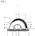
- FIG. 1 shows a schematic cross-sectional view of an arrangement for securing a flexible tube according to an embodiment of the invention.
- the flexible tube 3 is used, for example, for cable bushing in a vehicle and is to be attached to a component 4 with a flat footprint 4a.
- the flexible tube 3 may be designed in a conventional manner, for example as a corrugated tube, wherein the tube material may be made of vulcanized rubber or of a flexible plastic material.
- the flexible tube is first placed on the flat footprint 4a and then covered with a cover 6.
- the cover 6 is designed as a non-elastic plastic component.
- the cover has an arcuate cross-section and has two legs 6a, 6b, which extend away from an upper central shoulder 6c and with which the cover 6 is supported on both sides of the flexible tube 3 on the flat footprint 4a of the article 4.
- the cover 6 thus covers the flexible tube 3 at a longitudinal portion of the flexible tube 3 arcuate. Through the arcuate cross-section or through the inner sides of the legs, a recess 8 for receiving the flexible tube 3 is formed.
- the recess 8 is matched to the diameter of the flexible tube 3 or adapted to the outer contour of the flexible tube so that the cover 6 at an upper portion of the tube 3 surface, in particular form-fitting, rests.
- This area of the flexible tube 3, opposite to the object 4, is in FIG FIG. 1 denoted by the reference numeral 3e.
- a cable tie 5 is guided around the outer arcuate surface 6f of the cover element 6 and guided around the side 4b of the article 4 facing away from the flexible tube 3.
- slots 4c are correspondingly made in the article 4 for the passage of the cable tie 5.
- the cable tie is clamped by latching on the cable tie head 5a.
- the cable tie 5 thus does not touch the flexible tube directly at any point, but surrounds the cover element 6 and the component 4.
- the cover element 6 transmits the clamping force of the cable tie 5 to the flexible tube 3, but at the same time prevents excessive squeezing of the flexible tube 3.
- FIG. 3 This is schematic and exemplary in FIG. 3 shown.
- Under “I.” is the state of the flexible tube 3 in the normal state, that is shown in the non-assembled state in which no clamping force from the outside acts on the wall of the flexible tube 3.
- the cross section of the flexible tube 3 is circular.
- Under “II.” is the state of the flexible tube 3 in the assembled and tensioned state of FIG. 1 shown.
- FIG. 2 shows a cross-sectional view of an arrangement 2 for securing a flexible tube according to another embodiment of the invention.
- components with the same reference numerals correspond to the components of FIG. 1 and will not be described separately.
- a special feature of this embodiment is that the object on which the flexible tube 3 is to be fastened, a tube, here referred to as a support tube 9, is.
- the serving as Anti-crushing bridge cover 7 is again a component made of non-elastic plastic with an arcuate cross-section.
- the flexible tube 3 is first placed on the support tube 9 and then covered with the cover 7.
- the cover element 7 in turn has two legs 7a, 7b, which extend away from an upper central shoulder 7c and with which the cover 7 is supported on both sides by the flexible tube 3 on the outer wall of the support tube 9.
- the cover member 7 thus covers the flexible tube 3 at a longitudinal portion of the flexible tube 3 like an arc.
- the end faces 7 d of the legs 7 a, 7 b, with which the cover is supported on the support tube 3, have a curvature corresponding to the curvature of the support tube 9.
- the recess 8 is matched to the diameter of the flexible tube 3 or adapted to the outer contour of the flexible tube so that the cover 7 at an upper portion 3e of the tube 3 surface, in particular form-fitting, rests.
- the cable tie 5 is guided around the outer arcuate surface 7f of the cover element 7 and around the side facing away from the flexible tube 3 side 9b of the support tube 9, d. H. around a lower circular arc half of the support tube 9, guided around. Subsequently, the cable tie is clamped by latching on the cable tie head 5a.
- the cable tie 5 at no point directly touches the flexible tube 3, but is guided around the outside around the cover member 7 and the support tube 9.
- the flexible tube 3 can be fastened quickly and securely to the carrier tube 9, without causing excessive squeezing of the flexible tube 3.
Landscapes
- Engineering & Computer Science (AREA)
- General Engineering & Computer Science (AREA)
- Mechanical Engineering (AREA)
- Architecture (AREA)
- Civil Engineering (AREA)
- Structural Engineering (AREA)
- Details Of Indoor Wiring (AREA)
- Clamps And Clips (AREA)
- Supports For Pipes And Cables (AREA)
- Installation Of Indoor Wiring (AREA)
- Rigid Pipes And Flexible Pipes (AREA)
Abstract
Description
- Die Erfindung betrifft eine Anordnung zum Befestigen eines flexiblen Rohres, insbesondere eines Wellrohres, an einem Gegenstand, insbesondere an einem Bauteil eines Fahrzeugs.
- Im Fahrzeugbereich werden Wellrohre unter anderem zur Leitungsführung eingesetzt. So ist es üblich, flexible Leitungen, wie sie z. B. zur Versorgung von elektrischen Verbrauchern, wie z. B. Außenmarkierungsleuchten, oder zur Übertragung von Steuersignalen zwischen Steuergeräten und Sensoren verwendet werden, zu sich verzweigenden Leitungsbündeln zusammenzufassen. Um die Leitungsbündel, die auch als Kabelbäume bezeichnet werden, vor mechanischen Einflüssen zu schützen, werden diese häufig, zumindest abschnittweise, in flexiblen Wellrohren geführt, die meist aus Kunststoff gefertigt sind und das Leitungsbündel nur lose umschließen. Um einen derartigen Wellschlauch an einem Bauteil des Fahrzeugs zu befestigen, ist es aus der Praxis bekannt, das Wellrohr mittels eines Kabelbinders an dem Bauteil zu befestigen, wobei der Kabelbinder um das Wellrohr und um das Bauteil gelegt und festgespannt wird. Da der Kabelbinder direkt am Wellrohr anliegt, hat dieser bekannte Ansatz den Nachteil, dass ein Festspannen des Kabelbinders dazu führen kann, dass das Wellrohr zu stark gequetscht wird.
- Es ist somit eine Aufgabe der Erfindung, eine verbesserte Anordnung zum Befestigen eines flexiblen Rohres, insbesondere eines Wellrohres, an einem Gegenstand bereitzustellen, mit der Nachteile herkömmlicher Techniken vermieden werden können. Die Aufgabe der Erfindung ist es insbesondere, eine Anordnung zum Befestigen eines flexiblen Rohres unter Verwendung eines Spannbandes, z. B. eines Kabelbinders bereitzustellen, bei der das Risiko einer starken Quetschung des flexiblen Rohres vermieden wird.
- Diese Aufgaben werden durch eine Anordnung mit den Merkmalen des Anspruchs 1 gelöst. Vorteilhafte Ausführungsformen und Anwendungen der Erfindung sind Gegenstand der abhängigen Ansprüche und werden in der folgenden Beschreibung unter teilweiser Bezugnahme auf die Figuren näher erläutert.
- Gemäß allgemeinen Gesichtspunkten der Erfindung wird eine Anordnung zum Befestigen eines flexiblen Rohres an einem Gegenstand bereitgestellt. Der Gegenstand, an dem das flexible Rohr befestigt wird, kann insbesondere ein Bauteil eines Fahrzeugs sein. Die Anordnung umfasst ein flexibles Rohr, das auf den Gegenstand gelegt ist. Unter einem flexiblen Rohr soll ein langer, zylindrischer Hohlkörper verstanden werden, z. B. zur Durchführung von Fluiden oder elektrischen Leitungen, der ferner biegsam ist bzw. in Längsrichtung krümmbar ist. Das flexible Rohr kann insbesondere ein Wellrohr sein. Von dem Begriff "flexibles Rohr" sollen auch flexible Rohre umfasst sein, die aufgrund eines vergleichsweise kleinen Querschnitts üblicherweise als Schläuche bezeichnet werden. Das flexible Rohr kann insbesondere auch ein Wellschlauch sein. Durch das flexible Rohr kann z. B. mindestens eine elektrische Leitung geführt sein. Durch das flexible Rohr kann auch eine Fluidleitung, z. B. eine Spritzwasserleitung für eine Scheibenwaschanlage oder Lichtwellenleiter geführt sein. Das flexible Rohr kann auch ohne Inhalt sein.
- Die Anordnung umfasst ferner ein Abdeckelement für das flexible Rohr, welches sich beidseitig von dem flexiblen Rohr auf dem Gegenstand abstützt und das flexible Rohr an zumindest einem Abschnitt bogenartig bzw. brückenartig überdeckt, d. h. unter Ausbildung einer Wölbung. Das Abdeckelement kann beispielsweise in Längsrichtung des flexiblen Rohres gesehen einen U-förmigen, einen bogenförmigen oder einen V-förmigen Querschnitt aufweisen.
- Die Anordnung umfasst ferner ein Spannband, das um eine Außenseite des Abdeckelements und um eine dem flexiblen Rohr abgewandte Seite des Gegenstands herumgeführt ist. Um eine besonders schnelle Montage zu ermöglichen, kann das Spannband beispielsweise als Rastband, weiter vorzugsweise als selbstverrastendes Rastband ausgeführt sein. Das Spannband kann beispielsweise ein Kabelbinder sein.
- Die erfindungsgemäße Anordnung bietet den besonderen Vorzug, dass das Spannelement nur am Abdeckelement und am Gegenstand unmittelbar anliegt und angreift, das flexible Rohr jedoch nicht berührt. Das Spannelement erzeugt somit eine zum flexiblen Rohr gerichtete Spannkraft, die nur mittelbar über das Abdeckelement und den Gegenstand auf das flexible Rohr wirkt. Das Abdeckelement dient hierbei als Quetschschutz für das flexible Rohr und fungiert als Quetschschutzelement. Ein zu starkes Quetschen des Wellrohres kann somit vermieden werden. Gleichzeitig wird eine schnelle, unkomplizierte Befestigungsmöglichkeit für das flexible Rohr bereitgestellt. Der erfindungsgemäße Befestigungsansatz kann an allen problematischen Stellen an einem Fahrzeug eingesetzt werden, an denen das flexible Rohr gequetscht werden kann, z. B. an Stellen, an denen dünne Wellrohre mit wenig Füllgrad, z. B. zur elektrischen Versorgung von Außenmarkierungsleuchten, zum Einsatz kommen.
- Der Bereich, an dem das flexible Rohr auf dem Gegenstand aufliegt, bildet vorzugsweise eine sich in Längsrichtung des flexiblen Rohres erstreckende Mantellinie des flexiblen Rohres. Die Außenseite des Abdeckelements ist vorzugsweise eine dem Rohr abgewandte Außenfläche des Abdeckelements. Die Innenseite des Abdeckelements bildet vorzugsweise die dem flexiblen Rohr zugewandte Außenfläche des Abdeckelements, die einen Aufnahmeraum für das flexible Rohr ausbildet. Die dem flexiblen Rohr abgewandte Seite des Gegenstands umfasst vorzugsweise denjenigen Teil der Außenfläche des Gegenstands, an dem das Rohr nicht aufliegt.
- Ein besonders wirksamer Quetschschutz kann erzielt werden, falls das Abdeckelement aus einem nichtelastischen Werkstoff hergestellt ist. Eine besonders vorteilhafte Variante sieht hierbei vor, dass das Abdeckelement als nichtelastisches Kunststoffbauteil ausgeführt ist. Das Abdeckelement kann jedoch auch aus einem anderen Werkstoff, wie z. B. Metall oder Holz, gebildet sein.
- Gemäß einer bevorzugten Ausführungsform weist das Abdeckelement zwei Schenkel auf, mit denen sich das Abdeckelement beidseitig vom flexiblen Rohr auf dem Gegenstand abstützt. Gemäß dieser Ausführungsform ist eine durch die Innenseiten der Schenkel gebildete Ausnehmung zur Aufnahme des flexiblen Rohres so auf einen Durchmesser des flexiblen Rohres abgestimmt, dass das flexible Rohr an beiden Schenkeln anliegt. Dadurch wird das flexible Rohr durch Abdeckung mit dem Abdeckelement gleich auf dem Gegenstand fixiert.
- Bei einer vorteilhaften Variante dieser Ausführungsform ist eine dem flexiblen Rohr zugewandte Innenkontur der Abdeckung so an eine Außenkontur des flexiblen Rohres angepasst, so dass die Abdeckung an einer dem Gegenstand abgewandten Seite des flexiblen Rohres an diesem flächig, insbesondere formschlüssig, aufliegt.
- Eine Möglichkeit der erfindungsgemäßen Realisierung sieht ferner vor, dass der Gegenstand ein Trägerrohr mit größerem Durchmesser als das flexible Rohr ist und dass die Stirnflächen des Abdeckelements, mit denen sich das Abdeckelement auf dem Trägerrohr abstützt, eine Krümmung aufweisen, die der Krümmung des Trägerrohres entspricht. Hierdurch kann ein Abrutschen oder Verrutschen des Abdeckelements auf dem Trägerrohr besser verhindert werden.
- Eine alternative Möglichkeit der erfindungsgemäßen Realisierung sieht vor, dass der Gegenstand eine plane Aufstandsfläche aufweist, auf die das flexible Rohr gelegt ist. Hierbei können im Bereich der oder angrenzend zu den Stellen, an denen sich das Abdeckelement auf der planen Aufstandsfläche abstützt, Durchgangsöffnungen, insbesondere Schlitze, in der Aufstandsfläche vorgesehen sein, durch die das Spannband hindurch geführt ist.
- Die Erfindung betrifft ferner ein Kraftfahrzeug, insbesondere ein Nutzfahrzeug, mit einer Anordnung zum Befestigen eines flexiblen Rohres wie in diesem Dokument beschrieben.
- Die zuvor beschriebenen bevorzugten Ausführungsformen und Merkmale der Erfindung sind beliebig miteinander kombinierbar. Weitere Einzelheiten und Vorteile der Erfindung werden im Folgenden unter Bezug auf die beigefügten Zeichnungen beschrieben. Es zeigen:
- Figur 1
- eine Querschnittsansicht einer Anordnung zum Befestigen eines flexiblen Rohres gemäß einer Ausführungsform der Erfindung;
- Figur 2
- eine Querschnittsansicht einer Anordnung zum Befestigen eines flexiblen Rohres gemäß einer weiteren Ausführungsform der Erfindung; und
- Figur 3
- schematisch eine Querschnittsansicht eines flexiblen Rohres im nicht-montierten und im montierten Zustand.
-
Figur 1 zeigt eine schematische Querschnittsansicht einer Anordnung zum Befestigen eines flexiblen Rohres gemäß einer Ausführungsform der Erfindung. Das flexible Rohr 3 dient beispielsweise zur Leitungsdurchführung bei einem Fahrzeug und soll an einem Bauteil 4 mit einer planen Aufstandsfläche 4a befestigt werden. Das flexible Rohr 3 kann in herkömmlicher Weise ausgeführt sein, beispielsweise als Wellschlauch, wobei das Schlauchmaterial aus vulkanisiertem Kautschuk oder auch aus einem biegsamen Kunststoffmaterial bestehen kann. - Hierbei wird das flexible Rohr zunächst auf die plane Aufstandsfläche 4a gelegt und anschließend mit einem Abdeckelement 6 überdeckt.
- Das Abdeckelement 6 ist als nichtelastisches Kunststoffbauteil ausgeführt. Das Abdeckelement hat einen bogenförmigen Querschnitt und weist zwei Schenkel 6a, 6b auf, die sich ausgehend von einer oberen mittigen Schulter 6c wegerstrecken und mit denen sich das Abdeckelement 6 beidseitig vom flexiblen Rohr 3 auf der planen Aufstandsfläche 4a des Gegenstands 4 abstützt.
- Das Abdeckelement 6 überdeckt somit das flexible Rohr 3 an einem Längsabschnitt des flexiblen Rohres 3 bogenartig. Durch den bogenförmigen Querschnitt bzw. durch die Innenseiten der Schenkel wird eine Ausnehmung 8 zur Aufnahme des flexiblen Rohres 3 ausgebildet.
- Hierbei ist die Ausnehmung 8 so auf den Durchmesser des flexiblen Rohres 3 abgestimmt bzw. so an die Außenkontur des flexiblen Rohres angepasst, dass die Abdeckung 6 an einem oberen Bereich des Rohres 3 flächig, insbesondere formschlüssig, aufliegt. Dieser Bereich des flexiblen Rohres 3, gegenüberliegend zu dem Gegenstand 4, ist in
Figur 1 mit dem Bezugszeichen 3e gekennzeichnet. - Anschließend wird ein Kabelbinder 5 um die äußere bogenförmige Fläche 6f des Abdeckelements 6 geführt sowie um die dem flexiblen Rohr 3 abgewandte Seite 4b des Gegenstands 4 herumgeführt. Hierzu sind entsprechend Schlitze 4c in dem Gegenstand 4 zur Durchführung des Kabelbinders 5 eingebracht. Anschließend wird der Kabelbinder durch Verrastung am Kabelbinderkopf 5a gespannt.
- Der Kabelbinder 5 berührt somit an keiner Stelle direkt das flexible Rohr, sondern umschließt das Abdeckelement 6 und das Bauteil 4. Das Abdeckelement 6 überträgt die Spannkraft des Kabelbinders 5 auf das flexible Rohr 3, verhindert jedoch zugleich eine zu starke Quetschung des flexiblen Rohres 3. Dies ist schematisch und beispielhaft in
Figur 3 dargestellt. Unter "I." ist der Zustand des flexiblen Rohres 3 im Normalzustand, d. h. im nicht-montierten Zustand dargestellt, in dem keine Spannkraft von außen auf die Wandung des flexiblen Rohres 3 wirkt. Der Querschnitt des flexiblen Rohres 3 ist kreisförmig. Unter "II." ist der Zustand des flexiblen Rohres 3 im montierten und gespannten Zustand derFigur 1 dargestellt. Durch die von dem Abdeckelement 6 ausgeübte Spannkraft verformt sich das flexible Rohr 3 lediglich leicht, ohne gequetscht zu werden. -
Figur 2 zeigt eine Querschnittsansicht einer Anordnung 2 zum Befestigen eines flexiblen Rohres gemäß einer weiteren Ausführungsform der Erfindung. Hierbei entsprechen Komponenten mit gleichen Bezugszeichen den Komponenten derFigur 1 und werden nicht gesondert beschrieben. - Eine Besonderheit dieser Ausführungsform liegt darin, dass der Gegenstand, auf dem das flexible Rohr 3 befestigt werden soll, ein Rohr, hier als Trägerrohr 9 bezeichnet, ist. Das als Quetschschutzbrücke dienende Abdeckelement 7 ist wieder ein Bauteil aus nichtelastischem Kunststoff mit einem bogenförmigen Querschnitt.
- Zur Befestigung des flexiblen Rohres 3 am Trägerrohr 9 wird das flexible Rohr 3 zunächst auf das Trägerrohr 9 gelegt und anschließend mit dem Abdeckelement 7 überdeckt. Das Abdeckelement 7 weist wiederum zwei Schenkel 7a, 7b auf, die sich ausgehend von einer oberen mittigen Schulter 7c wegerstrecken und mit denen sich das Abdeckelement 7 beidseitig vom flexiblen Rohr 3 auf der äußeren Wandung des Trägerrohres 9 abstützt. Das Abdeckelement 7 überdeckt somit das flexible Rohr 3 an einem Längsabschnitt des flexiblen Rohres 3 bogenartig. Die Stirnflächen 7d der Schenkel 7a, 7b, mit denen sich das Abdeckelement auf dem Trägerrohr 3 abstützt, weisen eine Krümmung auf, die der Krümmung des Trägerrohres 9 entspricht. Hierbei ist die Ausnehmung 8 so auf den Durchmesser des flexiblen Rohres 3 abgestimmt bzw. so an die Außenkontur des flexiblen Rohres angepasst, dass die Abdeckung 7 an einem oberen Bereich 3e des Rohres 3 flächig, insbesondere formschlüssig, aufliegt.
- Anschließend wird der Kabelbinder 5 um die äußere bogenförmige Fläche 7f des Abdeckelements 7 geführt sowie um die dem flexiblen Rohr 3 abgewandte Seite 9b des Trägerrohrs 9, d. h. um eine untere Kreisbogenhälfte des Trägerrohres 9, herumgeführt. Anschließend wird der Kabelbinder durch Verrastung am Kabelbinderkopf 5a gespannt.
- Auch gemäß dieser Ausführungsform 2 berührt der Kabelbinder 5 an keiner Stelle direkt das flexible Rohr 3, sondern ist außen herum um das Abdeckelement 7 und das Trägerrohr 9 geführt. Hierdurch kann das flexible Rohr 3 schnell und sicher am Trägerrohr 9 befestigt werden, ohne dass es zu einer zu starken Quetschung des flexiblen Rohres 3 kommt.
- Obwohl die Erfindung unter Bezugnahme auf bestimmte Ausführungsbeispiele beschrieben worden ist, ist es für einen Fachmann ersichtlich, dass verschiedene Änderungen ausgeführt werden können und Äquivalente als Ersatz verwendet werden können, ohne den Bereich der Erfindung zu verlassen. Zusätzlich können viele Modifikationen ausgeführt werden, ohne den zugehörigen Bereich zu verlassen. Folglich soll die Erfindung nicht auf die offenbarten Ausführungsbeispiele begrenzt sein, sondern soll alle Ausführungsbeispiele umfassen, die in den Bereich der beigefügten Patentansprüche fallen. Insbesondere beansprucht die Erfindung auch Schutz für den Gegenstand und die Merkmale der Unteransprüche unabhängig von den in Bezug genommenen Ansprüchen.
-
- 1, 2
- Anordnung zum Befestigen eines flexiblen Rohres
- 3
- Flexibles Rohr
- 3e
- Oberer Bereich des flexiblen Rohres
- 4
- Gegenstand
- 4a
- Plane Aufstandsfläche
- 4b
- Unterseite des Gegenstands
- 4c
- Schlitze
- 5
- Spannband, insbesondere Kabelbinder
- 5a
- Kabelbinderkopf
- 6,7
- Abdeckelement
- 6a, 6b, 7a, 7b
- Schenkel
- 7c, 6c
- Schulter
- 7d
- Schenkelstirnfläche
- 6f, 7f
- Äußere bogenförmige Fläche
- 8
- Ausnehmung
- 9
- Trägerrohr
- 9b
- zum flexiblen Rohr abgewandte Seite des Trägerrohrs
Claims (10)
- Anordnung (1; 2) zum Befestigen eines flexiblen Rohres, insbesondere eines Wellrohres, an einem Gegenstand, insbesondere an einem Bauteil eines Fahrzeugs, umfassend:ein flexibles Rohr (3), das auf den Gegenstand (4; 9) gelegt ist;ein Abdeckelement (6 ,7), welches sich beidseitig vom flexiblen Rohr (3) auf dem Gegenstand (4; 9) abstützt und das flexible Rohr (3) an zumindest einem Abschnitt bogenartig überdeckt; undein Spannband (5), das um eine Außenseite (6f; 7f) des Abdeckelements (6; 7) und um eine dem flexiblen Rohr (3) abgewandte Seite (4b; 9b) des Gegenstands (4; 9) herumgeführt ist.
- Anordnung (1; 2) nach Anspruch 1, dadurch gekennzeichnet, dass das Abdeckelement einen U-förmigen, einen bogenförmigen oder einen V-förmigen Querschnitt zur Abdeckung des flexiblen Rohres (3) aufweist.
- Anordnung nach Anspruch 1 oder 2, dadurch gekennzeichnet,(a) dass das Abdeckelement (6 ,7) zwei Schenkel (6a, 6b; 7a, 7b) aufweist, mit denen sich das Abdeckelement (6 ,7) beidseitig vom flexiblen Rohr (3) auf dem Gegenstand (4; 9) abstützt; und(b) dass eine durch die Innenseiten der Schenkel gebildete Ausnehmung (8) zur Aufnahme des flexiblen Rohres (3) so auf einen Durchmesser des flexiblen Rohres abgestimmt ist, dass das flexible Rohr an beiden Schenkeln anliegt.
- Anordnung nach einem der vorhergehenden Ansprüche, dadurch gekennzeichnet, dass eine dem flexiblen Rohr zugewandte Innenkontur (6e) der Abdeckung (6; 7) so an eine Außenkontur des flexiblen Rohres angepasst ist, dass die Abdeckung an einer dem Gegenstand abgewandten Seite des flexiblen Rohres an diesem flächig, insbesondere formschlüssig, aufliegt.
- Anordnung nach einem der vorhergehenden Ansprüche, dadurch gekennzeichnet,(a) dass der Gegenstand ein Trägerrohr (9) mit größerem Durchmesser als das flexible Rohr (3) ist; und(b) dass die Stirnflächen (7d) des Abdeckelements (7), mit denen sich das Abdeckelement auf dem Trägerrohr abstützt, eine Krümmung aufweisen, die der Krümmung des Trägerrohres (9) entspricht.
- Anordnung nach einem der Ansprüche 1 bis 4, dadurch gekennzeichnet, dass der Gegenstand (4) eine plane Aufstandsfläche (4a) aufweist, auf die das flexible Rohr (3) gelegt ist und die im Bereich der oder angrenzend zu den Stellen, an denen sich das Abdeckelement auf der planen Aufstandsfläche (4a) abstützt, Durchgangsöffnungen, insbesondere Schlitze (4c), aufweist, durch die das Spannband (5) hindurchgeführt ist.
- Anordnung nach einem der vorhergehenden Ansprüche, dadurch gekennzeichnet,(a) dass das Spannband (5) als Rastband, weiter vorzugsweise als selbstverrastendes Rastband, ausgeführt ist; und/oder(b) dass das Spannband (5) ein Kabelbinder ist.
- Anordnung nach einem der vorhergehenden Ansprüche, dadurch gekennzeichnet,(a) dass das Abdeckelement (6; 7) aus einem nichtelastischen Werkstoff hergestellt ist; und/oder(b) dass das Abdeckelement (6; 7) als nichtelastisches Kunststoffbauteil ausgeführt ist.
- Anordnung nach einem der vorhergehenden Ansprüche, dadurch gekennzeichnet,(a) dass das flexible Rohr (3) ein Wellrohr oder ein Wellschlauch ist; und/oder(b) dass in dem flexiblen Rohr mindestens eine elektrische Leitung geführt ist.
- Kraftfahrzeug, insbesondere Nutzfahrzeug, mit einer Anordnung (1; 2) nach einem der vorhergehenden Ansprüche.
Priority Applications (1)
| Application Number | Priority Date | Filing Date | Title |
|---|---|---|---|
| PL16002182T PL3165802T3 (pl) | 2015-11-04 | 2016-10-10 | Układ do mocowania rury elastycznej, w szczególności rury falistej, na przedmiocie |
Applications Claiming Priority (1)
| Application Number | Priority Date | Filing Date | Title |
|---|---|---|---|
| DE102015014226.7A DE102015014226A1 (de) | 2015-11-04 | 2015-11-04 | Anordnung zum Befestigen eines flexiblen Rohres, insbesondere eines Wellrohres, an einem Gegenstand |
Publications (2)
| Publication Number | Publication Date |
|---|---|
| EP3165802A1 true EP3165802A1 (de) | 2017-05-10 |
| EP3165802B1 EP3165802B1 (de) | 2018-09-05 |
Family
ID=57130126
Family Applications (1)
| Application Number | Title | Priority Date | Filing Date |
|---|---|---|---|
| EP16002182.0A Active EP3165802B1 (de) | 2015-11-04 | 2016-10-10 | Anordnung zum befestigen eines flexiblen rohres, insbesondere eines wellrohres, an einem gegenstand |
Country Status (8)
| Country | Link |
|---|---|
| US (1) | US10024462B2 (de) |
| EP (1) | EP3165802B1 (de) |
| CN (1) | CN107023714B (de) |
| BR (1) | BR102016024686B1 (de) |
| DE (1) | DE102015014226A1 (de) |
| HU (1) | HUE042113T2 (de) |
| PL (1) | PL3165802T3 (de) |
| RU (1) | RU2721520C2 (de) |
Cited By (1)
| Publication number | Priority date | Publication date | Assignee | Title |
|---|---|---|---|---|
| CN110966032A (zh) * | 2019-12-24 | 2020-04-07 | 中国矿业大学徐海学院 | 一种防护功能的煤矿通风用支撑装置 |
Citations (4)
| Publication number | Priority date | Publication date | Assignee | Title |
|---|---|---|---|---|
| US6010099A (en) * | 1997-12-17 | 2000-01-04 | The Whitaker Corporation | Dimple forming clamp used to hold spring jacketed cable |
| DE102010007983A1 (de) * | 2010-02-15 | 2011-08-18 | Linde Material Handling GmbH, 63743 | Befestigungsvorrichtung zur Befestigung eines Rundprofilelements an einem Rundprofilträger |
| US20140131528A1 (en) * | 2012-11-12 | 2014-05-15 | Airbus Operations Limited | Mount for cable harness |
| US20150237770A1 (en) * | 2012-08-27 | 2015-08-20 | Furukawa Automotive Systems Inc. | Electromagnetic shielding tube |
Family Cites Families (18)
| Publication number | Priority date | Publication date | Assignee | Title |
|---|---|---|---|---|
| US3243151A (en) * | 1964-04-13 | 1966-03-29 | Richard C Varney | Self-holding pipe strap |
| US3711632A (en) | 1971-12-02 | 1973-01-16 | Gen Motors Corp | End fitting for corrugated conduit |
| US3848839A (en) * | 1972-01-25 | 1974-11-19 | G Tillman | Conduit support clamp |
| US4258515A (en) * | 1977-09-13 | 1981-03-31 | Owen William J | Conduit trunking |
| SU1255799A1 (ru) * | 1984-12-27 | 1986-09-07 | Филиал "Проектэнерговентиляция" Проектно-Конструкторского Бюро Главэнергостроймеханизации | Устройство дл креплени трубопровода к поперечной профильной балке |
| WO1997016666A1 (en) * | 1995-10-30 | 1997-05-09 | Capro, Inc. | Control cable mounting system |
| US6105907A (en) * | 1998-12-19 | 2000-08-22 | Ta Mfg Co. | Apparatus and method for supporting and/or holding a payload |
| DE60206090T2 (de) * | 2001-03-16 | 2006-06-14 | Yazaki Corp | Kabelbaumanordnung für eine Kraftfahrzeugschiebetür |
| JP3741998B2 (ja) | 2001-11-14 | 2006-02-01 | 矢崎総業株式会社 | コルゲートチューブ用回転保持具 |
| US6729588B2 (en) * | 2001-11-16 | 2004-05-04 | Wilkinson, Iii Joseph | Pipe shoe and method |
| US7722001B2 (en) * | 2005-11-29 | 2010-05-25 | Illinois Tool Works Inc. | Bar clamp assembly |
| US7770848B2 (en) | 2007-11-29 | 2010-08-10 | The Boeing Company | Clamp for securing an object to a structure |
| WO2009132988A1 (en) * | 2008-04-28 | 2009-11-05 | Thuesen Joergen | A clamp for securing a pipe to a supporting structure |
| GB201202883D0 (en) | 2012-02-20 | 2012-04-04 | Airbus Operations Ltd | Clamp block assembly |
| JP5913008B2 (ja) | 2012-09-03 | 2016-04-27 | 矢崎総業株式会社 | ハーネス保護チューブのクランプ構造 |
| JP5895894B2 (ja) | 2013-04-12 | 2016-03-30 | 住友電装株式会社 | バンドクリップ、バンドクリップ付きワイヤーハーネス及び組み立て品 |
| US9512941B2 (en) * | 2013-07-23 | 2016-12-06 | Hawken Holdings, Llc | Conduit guide apparatus, system, and method |
| FR3016749B1 (fr) | 2014-01-20 | 2016-02-26 | Leoni Wiring Systems France | Dispositif de fixation sur un support d'un organe longiligne formant un faisceau de cables ou une gaine de faisceau de cables pour vehicule automobile |
-
2015
- 2015-11-04 DE DE102015014226.7A patent/DE102015014226A1/de not_active Withdrawn
-
2016
- 2016-10-10 EP EP16002182.0A patent/EP3165802B1/de active Active
- 2016-10-10 HU HUE16002182A patent/HUE042113T2/hu unknown
- 2016-10-10 PL PL16002182T patent/PL3165802T3/pl unknown
- 2016-10-21 BR BR102016024686-5A patent/BR102016024686B1/pt active IP Right Grant
- 2016-11-02 RU RU2016143097A patent/RU2721520C2/ru active
- 2016-11-03 CN CN201610951245.1A patent/CN107023714B/zh active Active
- 2016-11-04 US US15/343,753 patent/US10024462B2/en active Active
Patent Citations (4)
| Publication number | Priority date | Publication date | Assignee | Title |
|---|---|---|---|---|
| US6010099A (en) * | 1997-12-17 | 2000-01-04 | The Whitaker Corporation | Dimple forming clamp used to hold spring jacketed cable |
| DE102010007983A1 (de) * | 2010-02-15 | 2011-08-18 | Linde Material Handling GmbH, 63743 | Befestigungsvorrichtung zur Befestigung eines Rundprofilelements an einem Rundprofilträger |
| US20150237770A1 (en) * | 2012-08-27 | 2015-08-20 | Furukawa Automotive Systems Inc. | Electromagnetic shielding tube |
| US20140131528A1 (en) * | 2012-11-12 | 2014-05-15 | Airbus Operations Limited | Mount for cable harness |
Cited By (1)
| Publication number | Priority date | Publication date | Assignee | Title |
|---|---|---|---|---|
| CN110966032A (zh) * | 2019-12-24 | 2020-04-07 | 中国矿业大学徐海学院 | 一种防护功能的煤矿通风用支撑装置 |
Also Published As
| Publication number | Publication date |
|---|---|
| DE102015014226A1 (de) | 2017-05-04 |
| CN107023714B (zh) | 2020-11-13 |
| PL3165802T3 (pl) | 2019-05-31 |
| RU2016143097A3 (de) | 2020-03-25 |
| EP3165802B1 (de) | 2018-09-05 |
| US10024462B2 (en) | 2018-07-17 |
| RU2721520C2 (ru) | 2020-05-19 |
| CN107023714A (zh) | 2017-08-08 |
| BR102016024686A2 (pt) | 2017-05-09 |
| US20170122461A1 (en) | 2017-05-04 |
| RU2016143097A (ru) | 2018-05-07 |
| BR102016024686B1 (pt) | 2022-08-02 |
| HUE042113T2 (hu) | 2019-06-28 |
Similar Documents
| Publication | Publication Date | Title |
|---|---|---|
| WO2018015043A1 (de) | Stützhülse | |
| EP3569916B1 (de) | Haltevorrichtung zum befestigen einer isolierung | |
| DE102010044665A1 (de) | Befestigungseinrichtung mit einer Ausgleichsschiene zum Toleranzausgleich | |
| DE4018905A1 (de) | Kabelzugentlastung | |
| DE10214966C1 (de) | Schelle zum achsparallelen Verbinden eines zylindrischen Temperaturfühlers mit einem Rohr | |
| EP2193304B1 (de) | Sicherungseinrichtung für eine insbesondere Pressverbindung zwischen einer Schlauchleitung und einer Anschlussarmatur | |
| EP3165802B1 (de) | Anordnung zum befestigen eines flexiblen rohres, insbesondere eines wellrohres, an einem gegenstand | |
| DE102014215394B3 (de) | Hochschalldämmende Rohrbefestigungsvorrichtung | |
| EP2982896A1 (de) | Hochschalldämmende rohrbefestigungsvorrichtung | |
| DE102014116468B4 (de) | Befestigungselement und Kabelschacht | |
| DE20108139U1 (de) | Klemmvorrichtung | |
| CH684114A5 (de) | Rohrschelle. | |
| DE102011106912B4 (de) | Befestigungsclip zur Halterung eines länglichen Bauteils, insbesondere von Rohren, Leitungen oder Kabelbünden in Kraftfahrzeugen | |
| EP1265020B1 (de) | Flexible Gasleitung | |
| KR101833022B1 (ko) | 유볼트형 클램프 | |
| DE102008046134A1 (de) | Schlauchleitung, insbesondere Hydraulikleitung | |
| DE2600725A1 (de) | Aus einem federstahlstreifen gebildete haltefeder | |
| DE102007031405A1 (de) | Halteeinrichtung | |
| AT1847U1 (de) | Schutzhülse für eine verbindung zwischen einem flexiblen rohr und einer anschlussarmatur oder einem fitting | |
| DE102010007983A1 (de) | Befestigungsvorrichtung zur Befestigung eines Rundprofilelements an einem Rundprofilträger | |
| AT14868U1 (de) | Kabelhalter | |
| EP3995724B1 (de) | Rohrschelle | |
| DE19542335C2 (de) | Flexible Hauseinführung für eine Gasleitung | |
| DE102007012536B4 (de) | Leitung mit Knickschutzhülse und Knickschutzhülse | |
| DE1169543B (de) | Stopfbuchsenartige Einfuehrung fuer ein elektrisches Kabel in Gehaeuse elektrischer Geraete unter Benutzung eines das Kabel umgebenden flexiblen Schlauches |
Legal Events
| Date | Code | Title | Description |
|---|---|---|---|
| PUAI | Public reference made under article 153(3) epc to a published international application that has entered the european phase |
Free format text: ORIGINAL CODE: 0009012 |
|
| STAA | Information on the status of an ep patent application or granted ep patent |
Free format text: STATUS: THE APPLICATION HAS BEEN PUBLISHED |
|
| AK | Designated contracting states |
Kind code of ref document: A1 Designated state(s): AL AT BE BG CH CY CZ DE DK EE ES FI FR GB GR HR HU IE IS IT LI LT LU LV MC MK MT NL NO PL PT RO RS SE SI SK SM TR |
|
| AX | Request for extension of the european patent |
Extension state: BA ME |
|
| STAA | Information on the status of an ep patent application or granted ep patent |
Free format text: STATUS: REQUEST FOR EXAMINATION WAS MADE |
|
| 17P | Request for examination filed |
Effective date: 20171108 |
|
| RBV | Designated contracting states (corrected) |
Designated state(s): AL AT BE BG CH CY CZ DE DK EE ES FI FR GB GR HR HU IE IS IT LI LT LU LV MC MK MT NL NO PL PT RO RS SE SI SK SM TR |
|
| GRAP | Despatch of communication of intention to grant a patent |
Free format text: ORIGINAL CODE: EPIDOSNIGR1 |
|
| STAA | Information on the status of an ep patent application or granted ep patent |
Free format text: STATUS: GRANT OF PATENT IS INTENDED |
|
| RIC1 | Information provided on ipc code assigned before grant |
Ipc: B60R 16/02 20060101ALI20180308BHEP Ipc: F16L 3/137 20060101ALN20180308BHEP Ipc: F16L 3/237 20060101ALN20180308BHEP Ipc: F16L 3/04 20060101AFI20180308BHEP |
|
| RIC1 | Information provided on ipc code assigned before grant |
Ipc: F16L 3/04 20060101AFI20180309BHEP Ipc: F16L 3/237 20060101ALN20180309BHEP Ipc: B60R 16/02 20060101ALI20180309BHEP Ipc: F16L 3/137 20060101ALN20180309BHEP |
|
| INTG | Intention to grant announced |
Effective date: 20180410 |
|
| GRAS | Grant fee paid |
Free format text: ORIGINAL CODE: EPIDOSNIGR3 |
|
| GRAA | (expected) grant |
Free format text: ORIGINAL CODE: 0009210 |
|
| STAA | Information on the status of an ep patent application or granted ep patent |
Free format text: STATUS: THE PATENT HAS BEEN GRANTED |
|
| AK | Designated contracting states |
Kind code of ref document: B1 Designated state(s): AL AT BE BG CH CY CZ DE DK EE ES FI FR GB GR HR HU IE IS IT LI LT LU LV MC MK MT NL NO PL PT RO RS SE SI SK SM TR |
|
| REG | Reference to a national code |
Ref country code: GB Ref legal event code: FG4D Free format text: NOT ENGLISH |
|
| REG | Reference to a national code |
Ref country code: CH Ref legal event code: EP |
|
| REG | Reference to a national code |
Ref country code: AT Ref legal event code: REF Ref document number: 1038209 Country of ref document: AT Kind code of ref document: T Effective date: 20180915 |
|
| REG | Reference to a national code |
Ref country code: IE Ref legal event code: FG4D Free format text: LANGUAGE OF EP DOCUMENT: GERMAN |
|
| REG | Reference to a national code |
Ref country code: DE Ref legal event code: R096 Ref document number: 502016001831 Country of ref document: DE |
|
| REG | Reference to a national code |
Ref country code: NL Ref legal event code: FP |
|
| REG | Reference to a national code |
Ref country code: FR Ref legal event code: PLFP Year of fee payment: 3 |
|
| REG | Reference to a national code |
Ref country code: SE Ref legal event code: TRGR |
|
| REG | Reference to a national code |
Ref country code: LT Ref legal event code: MG4D |
|
| PG25 | Lapsed in a contracting state [announced via postgrant information from national office to epo] |
Ref country code: GR Free format text: LAPSE BECAUSE OF FAILURE TO SUBMIT A TRANSLATION OF THE DESCRIPTION OR TO PAY THE FEE WITHIN THE PRESCRIBED TIME-LIMIT Effective date: 20181206 Ref country code: NO Free format text: LAPSE BECAUSE OF FAILURE TO SUBMIT A TRANSLATION OF THE DESCRIPTION OR TO PAY THE FEE WITHIN THE PRESCRIBED TIME-LIMIT Effective date: 20181205 Ref country code: RS Free format text: LAPSE BECAUSE OF FAILURE TO SUBMIT A TRANSLATION OF THE DESCRIPTION OR TO PAY THE FEE WITHIN THE PRESCRIBED TIME-LIMIT Effective date: 20180905 Ref country code: FI Free format text: LAPSE BECAUSE OF FAILURE TO SUBMIT A TRANSLATION OF THE DESCRIPTION OR TO PAY THE FEE WITHIN THE PRESCRIBED TIME-LIMIT Effective date: 20180905 Ref country code: LT Free format text: LAPSE BECAUSE OF FAILURE TO SUBMIT A TRANSLATION OF THE DESCRIPTION OR TO PAY THE FEE WITHIN THE PRESCRIBED TIME-LIMIT Effective date: 20180905 Ref country code: BG Free format text: LAPSE BECAUSE OF FAILURE TO SUBMIT A TRANSLATION OF THE DESCRIPTION OR TO PAY THE FEE WITHIN THE PRESCRIBED TIME-LIMIT Effective date: 20181205 |
|
| PG25 | Lapsed in a contracting state [announced via postgrant information from national office to epo] |
Ref country code: AL Free format text: LAPSE BECAUSE OF FAILURE TO SUBMIT A TRANSLATION OF THE DESCRIPTION OR TO PAY THE FEE WITHIN THE PRESCRIBED TIME-LIMIT Effective date: 20180905 Ref country code: LV Free format text: LAPSE BECAUSE OF FAILURE TO SUBMIT A TRANSLATION OF THE DESCRIPTION OR TO PAY THE FEE WITHIN THE PRESCRIBED TIME-LIMIT Effective date: 20180905 Ref country code: HR Free format text: LAPSE BECAUSE OF FAILURE TO SUBMIT A TRANSLATION OF THE DESCRIPTION OR TO PAY THE FEE WITHIN THE PRESCRIBED TIME-LIMIT Effective date: 20180905 |
|
| PG25 | Lapsed in a contracting state [announced via postgrant information from national office to epo] |
Ref country code: IS Free format text: LAPSE BECAUSE OF FAILURE TO SUBMIT A TRANSLATION OF THE DESCRIPTION OR TO PAY THE FEE WITHIN THE PRESCRIBED TIME-LIMIT Effective date: 20190105 Ref country code: EE Free format text: LAPSE BECAUSE OF FAILURE TO SUBMIT A TRANSLATION OF THE DESCRIPTION OR TO PAY THE FEE WITHIN THE PRESCRIBED TIME-LIMIT Effective date: 20180905 Ref country code: RO Free format text: LAPSE BECAUSE OF FAILURE TO SUBMIT A TRANSLATION OF THE DESCRIPTION OR TO PAY THE FEE WITHIN THE PRESCRIBED TIME-LIMIT Effective date: 20180905 Ref country code: CZ Free format text: LAPSE BECAUSE OF FAILURE TO SUBMIT A TRANSLATION OF THE DESCRIPTION OR TO PAY THE FEE WITHIN THE PRESCRIBED TIME-LIMIT Effective date: 20180905 Ref country code: ES Free format text: LAPSE BECAUSE OF FAILURE TO SUBMIT A TRANSLATION OF THE DESCRIPTION OR TO PAY THE FEE WITHIN THE PRESCRIBED TIME-LIMIT Effective date: 20180905 |
|
| PG25 | Lapsed in a contracting state [announced via postgrant information from national office to epo] |
Ref country code: SK Free format text: LAPSE BECAUSE OF FAILURE TO SUBMIT A TRANSLATION OF THE DESCRIPTION OR TO PAY THE FEE WITHIN THE PRESCRIBED TIME-LIMIT Effective date: 20180905 Ref country code: PT Free format text: LAPSE BECAUSE OF FAILURE TO SUBMIT A TRANSLATION OF THE DESCRIPTION OR TO PAY THE FEE WITHIN THE PRESCRIBED TIME-LIMIT Effective date: 20190105 Ref country code: SM Free format text: LAPSE BECAUSE OF FAILURE TO SUBMIT A TRANSLATION OF THE DESCRIPTION OR TO PAY THE FEE WITHIN THE PRESCRIBED TIME-LIMIT Effective date: 20180905 |
|
| REG | Reference to a national code |
Ref country code: DE Ref legal event code: R097 Ref document number: 502016001831 Country of ref document: DE |
|
| REG | Reference to a national code |
Ref country code: BE Ref legal event code: MM Effective date: 20181031 |
|
| PG25 | Lapsed in a contracting state [announced via postgrant information from national office to epo] |
Ref country code: LU Free format text: LAPSE BECAUSE OF NON-PAYMENT OF DUE FEES Effective date: 20181010 |
|
| REG | Reference to a national code |
Ref country code: HU Ref legal event code: AG4A Ref document number: E042113 Country of ref document: HU |
|
| PLBE | No opposition filed within time limit |
Free format text: ORIGINAL CODE: 0009261 |
|
| STAA | Information on the status of an ep patent application or granted ep patent |
Free format text: STATUS: NO OPPOSITION FILED WITHIN TIME LIMIT |
|
| RAP2 | Party data changed (patent owner data changed or rights of a patent transferred) |
Owner name: MAN TRUCK & BUS SE |
|
| REG | Reference to a national code |
Ref country code: IE Ref legal event code: MM4A |
|
| PG25 | Lapsed in a contracting state [announced via postgrant information from national office to epo] |
Ref country code: DK Free format text: LAPSE BECAUSE OF FAILURE TO SUBMIT A TRANSLATION OF THE DESCRIPTION OR TO PAY THE FEE WITHIN THE PRESCRIBED TIME-LIMIT Effective date: 20180905 Ref country code: MC Free format text: LAPSE BECAUSE OF FAILURE TO SUBMIT A TRANSLATION OF THE DESCRIPTION OR TO PAY THE FEE WITHIN THE PRESCRIBED TIME-LIMIT Effective date: 20180905 |
|
| 26N | No opposition filed |
Effective date: 20190606 |
|
| PG25 | Lapsed in a contracting state [announced via postgrant information from national office to epo] |
Ref country code: BE Free format text: LAPSE BECAUSE OF NON-PAYMENT OF DUE FEES Effective date: 20181031 Ref country code: SI Free format text: LAPSE BECAUSE OF FAILURE TO SUBMIT A TRANSLATION OF THE DESCRIPTION OR TO PAY THE FEE WITHIN THE PRESCRIBED TIME-LIMIT Effective date: 20180905 |
|
| REG | Reference to a national code |
Ref country code: DE Ref legal event code: R081 Ref document number: 502016001831 Country of ref document: DE Owner name: MAN TRUCK & BUS SE, DE Free format text: FORMER OWNER: MAN TRUCK & BUS AG, 80995 MUENCHEN, DE |
|
| PG25 | Lapsed in a contracting state [announced via postgrant information from national office to epo] |
Ref country code: IE Free format text: LAPSE BECAUSE OF NON-PAYMENT OF DUE FEES Effective date: 20181010 |
|
| PG25 | Lapsed in a contracting state [announced via postgrant information from national office to epo] |
Ref country code: MT Free format text: LAPSE BECAUSE OF FAILURE TO SUBMIT A TRANSLATION OF THE DESCRIPTION OR TO PAY THE FEE WITHIN THE PRESCRIBED TIME-LIMIT Effective date: 20180905 |
|
| REG | Reference to a national code |
Ref country code: CH Ref legal event code: PL |
|
| PG25 | Lapsed in a contracting state [announced via postgrant information from national office to epo] |
Ref country code: CY Free format text: LAPSE BECAUSE OF FAILURE TO SUBMIT A TRANSLATION OF THE DESCRIPTION OR TO PAY THE FEE WITHIN THE PRESCRIBED TIME-LIMIT Effective date: 20180905 Ref country code: MK Free format text: LAPSE BECAUSE OF NON-PAYMENT OF DUE FEES Effective date: 20180905 |
|
| PG25 | Lapsed in a contracting state [announced via postgrant information from national office to epo] |
Ref country code: CH Free format text: LAPSE BECAUSE OF NON-PAYMENT OF DUE FEES Effective date: 20191031 Ref country code: LI Free format text: LAPSE BECAUSE OF NON-PAYMENT OF DUE FEES Effective date: 20191031 |
|
| GBPC | Gb: european patent ceased through non-payment of renewal fee |
Effective date: 20201010 |
|
| PG25 | Lapsed in a contracting state [announced via postgrant information from national office to epo] |
Ref country code: GB Free format text: LAPSE BECAUSE OF NON-PAYMENT OF DUE FEES Effective date: 20201010 |
|
| REG | Reference to a national code |
Ref country code: AT Ref legal event code: MM01 Ref document number: 1038209 Country of ref document: AT Kind code of ref document: T Effective date: 20211010 |
|
| PG25 | Lapsed in a contracting state [announced via postgrant information from national office to epo] |
Ref country code: AT Free format text: LAPSE BECAUSE OF NON-PAYMENT OF DUE FEES Effective date: 20211010 |
|
| PGFP | Annual fee paid to national office [announced via postgrant information from national office to epo] |
Ref country code: PL Payment date: 20250929 Year of fee payment: 10 Ref country code: TR Payment date: 20250929 Year of fee payment: 10 |
|
| PGFP | Annual fee paid to national office [announced via postgrant information from national office to epo] |
Ref country code: HU Payment date: 20251009 Year of fee payment: 10 |
|
| PGFP | Annual fee paid to national office [announced via postgrant information from national office to epo] |
Ref country code: NL Payment date: 20251024 Year of fee payment: 10 |
|
| PGFP | Annual fee paid to national office [announced via postgrant information from national office to epo] |
Ref country code: DE Payment date: 20251028 Year of fee payment: 10 |
|
| PGFP | Annual fee paid to national office [announced via postgrant information from national office to epo] |
Ref country code: IT Payment date: 20251022 Year of fee payment: 10 |
|
| PGFP | Annual fee paid to national office [announced via postgrant information from national office to epo] |
Ref country code: FR Payment date: 20251027 Year of fee payment: 10 |
|
| PGFP | Annual fee paid to national office [announced via postgrant information from national office to epo] |
Ref country code: SE Payment date: 20251024 Year of fee payment: 10 |