EP3165408A1 - Automatischer insassenairbagschalter - Google Patents
Automatischer insassenairbagschalter Download PDFInfo
- Publication number
- EP3165408A1 EP3165408A1 EP16195427.6A EP16195427A EP3165408A1 EP 3165408 A1 EP3165408 A1 EP 3165408A1 EP 16195427 A EP16195427 A EP 16195427A EP 3165408 A1 EP3165408 A1 EP 3165408A1
- Authority
- EP
- European Patent Office
- Prior art keywords
- airbag
- vehicle seat
- image information
- airbag deployment
- threshold
- Prior art date
- Legal status (The legal status is an assumption and is not a legal conclusion. Google has not performed a legal analysis and makes no representation as to the accuracy of the status listed.)
- Granted
Links
Images

Classifications
-
- B—PERFORMING OPERATIONS; TRANSPORTING
- B60—VEHICLES IN GENERAL
- B60R—VEHICLES, VEHICLE FITTINGS, OR VEHICLE PARTS, NOT OTHERWISE PROVIDED FOR
- B60R21/00—Arrangements or fittings on vehicles for protecting or preventing injuries to occupants or pedestrians in case of accidents or other traffic risks
- B60R21/01—Electrical circuits for triggering passive safety arrangements, e.g. airbags, safety belt tighteners, in case of vehicle accidents or impending vehicle accidents
- B60R21/015—Electrical circuits for triggering passive safety arrangements, e.g. airbags, safety belt tighteners, in case of vehicle accidents or impending vehicle accidents including means for detecting the presence or position of passengers, passenger seats or child seats, and the related safety parameters therefor, e.g. speed or timing of airbag inflation in relation to occupant position or seat belt use
- B60R21/01512—Passenger detection systems
- B60R21/01552—Passenger detection systems detecting position of specific human body parts, e.g. face, eyes or hands
-
- B—PERFORMING OPERATIONS; TRANSPORTING
- B60—VEHICLES IN GENERAL
- B60R—VEHICLES, VEHICLE FITTINGS, OR VEHICLE PARTS, NOT OTHERWISE PROVIDED FOR
- B60R21/00—Arrangements or fittings on vehicles for protecting or preventing injuries to occupants or pedestrians in case of accidents or other traffic risks
- B60R21/01—Electrical circuits for triggering passive safety arrangements, e.g. airbags, safety belt tighteners, in case of vehicle accidents or impending vehicle accidents
- B60R21/015—Electrical circuits for triggering passive safety arrangements, e.g. airbags, safety belt tighteners, in case of vehicle accidents or impending vehicle accidents including means for detecting the presence or position of passengers, passenger seats or child seats, and the related safety parameters therefor, e.g. speed or timing of airbag inflation in relation to occupant position or seat belt use
- B60R21/01512—Passenger detection systems
- B60R21/01516—Passenger detection systems using force or pressure sensing means
-
- B—PERFORMING OPERATIONS; TRANSPORTING
- B60—VEHICLES IN GENERAL
- B60R—VEHICLES, VEHICLE FITTINGS, OR VEHICLE PARTS, NOT OTHERWISE PROVIDED FOR
- B60R21/00—Arrangements or fittings on vehicles for protecting or preventing injuries to occupants or pedestrians in case of accidents or other traffic risks
- B60R21/01—Electrical circuits for triggering passive safety arrangements, e.g. airbags, safety belt tighteners, in case of vehicle accidents or impending vehicle accidents
- B60R21/015—Electrical circuits for triggering passive safety arrangements, e.g. airbags, safety belt tighteners, in case of vehicle accidents or impending vehicle accidents including means for detecting the presence or position of passengers, passenger seats or child seats, and the related safety parameters therefor, e.g. speed or timing of airbag inflation in relation to occupant position or seat belt use
- B60R21/01512—Passenger detection systems
- B60R21/0153—Passenger detection systems using field detection presence sensors
- B60R21/01538—Passenger detection systems using field detection presence sensors for image processing, e.g. cameras or sensor arrays
Definitions
- an airbag system can often save an adult's life, it can cause serious damage, or even death, to a small child or infant.
- a driver may wish to turn on or off a passenger seat airbag.
- Manual airbag systems are problematic for a number of reasons. For example, a driver may not know how to turn the airbag system on or off. Additionally, the driver may forget to reactivate the airbag system upon removing the small child, which might result in the death of an adult riding in the passenger seat.
- the disclosure provides an improved automatic airbag deployment system in which the airbag deployment device is activated or deactivated upon determining that an object situated in a vehicle seat is a person meeting one or more criteria.
- the automatic airbag deployment system described includes a number of sensors configured to detect various attributes of an object situated in the vehicle seat. Each of the sensors may be activated sequentially or simultaneously to gather input related to the object that may be processed by a processor device.
- the processor device receives digital image input from a camera sensor device, which may be processed, using one or more image processing techniques, to determine whether the object is a person meeting the one or more criteria.
- an airbag deployment system configured to automatically activate and deactivate an airbag deployment device based on whether particular conditions are met.
- the airbag deployment system may detect that a weight threshold has been met by an object or person situated in vehicle's passenger seat.
- the airbag deployment system may include a height detection device configured to determine whether the height of the object or person situated in vehicle's passenger seat meets a threshold height.
- the airbag deployment system may utilize one or more facial recognition techniques to determine an identity of a person in the passenger seat. The person's identity may be used to apply one or more personal configuration settings to the airbag deployment system.
- an airbag deployment system may be configured to activate a passenger airbag deployment device only when a person seated in the passenger seat meets certain criteria.
- the airbag deployment system may include a number of sensors designed to detect whether an object situated in the passenger seat of a vehicle is a person.
- the airbag deployment system may include a number of sensors configured to detect a weight, height, and/or age of the person seated in the passenger seat.
- the airbag deployment system may be configured to make a determination regarding an object positioned in the vehicle seat upon detecting an initialization event (e.g., a startup of the car's engine, buckling of a safety belt, closing of a door, etc.).
- an initialization event e.g., a startup of the car's engine, buckling of a safety belt, closing of a door, etc.
- a weight or pressure applied to the vehicle seat may constitute an initialization event that triggers one or more of the described processes. If the passenger seat is not occupied by a person, or that person does not meet the weight, height, and/or age requirements, then the airbag deployment device may be shut off or deactivated.
- the verification process to determine whether a person meets the criteria for activating the airbag deployment device may be initiated by the airbag deployment system upon detecting a pressure or weight in the passenger seat.
- the weight of the passenger may be detected through the use of a weight or pressure sensor.
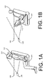
- FIG. 1 depicts an illustrative example of an airbag deployment system in accordance with at least some embodiments.
- FIG. 1 has been divided into FIG. 1A and FIG. 1B .
- a vehicle seat 102 of an airbag deployment system is depicted as having a pressure sensor 104.
- the airbag deployment system may include a camera device 106 and/or a height detection device 108.
- the pressure sensor 104 may be any device or sensor configured to detect a total amount of pressure applied to the vehicle seat 102.
- the pressure sensor 104 may be a load cell (e.g., a hydraulic load cell, a strain gauge load cell, or a pneumatic load cell).
- the airbag deployment system may include a processor device that compares an indication of the pressure detected by the pressure sensor against a pre-programmed threshold pressure.
- the pressure sensor may be hard wired to provide a signal only if the pressure detected is greater than a predetermined threshold.
- a load cell may be wired in series with a comparator circuit, such that a signal will be generated by the comparator circuit if a signal received from the load cell exceeds a threshold signal provided to the comparator circuit.
- the camera device 106 may be any device configured to capture image information associated with an object in the vehicle seat 102.
- the camera device 106 may be a digital camera.
- the camera device 106 may be configured to capture video or a series of images.
- the camera device 106 may be configured to capture images on a periodic basis.
- Image information captured by camera device 106 may be processed by a processing device, which will be described in greater detail below.
- the processing device may determine, from the image information captured by the camera 106, a location of at least one eye structure in the image information.
- the height detection device 108 may be any device configured to determine whether the height of an object or person situated in the vehicle seat 102 is greater than a threshold height.
- the height detection device 108 may include one or more pyroelectric sensors capable of detecting infrared rays emitted by the human body.
- the pyroelectric sensors may be installed on the ceiling of the vehicle to detect the height of the object (and whether the object is a person) by determining a distance of the object from the ceiling.
- the height detection device 108 may comprise a light beam emitted across a space occupied by an object in the vehicle seat 102 at the height threshold. If the light beam is obstructed, then the height sensor 108 may determine that the height threshold has been met.
- the camera device 106 may also be the height detection device 108.
- one or more image processing techniques may be used to determine a person's height from an image of the person captured by the camera device 108.
- the camera device 106 when the pressure sensor 104 detects that an object has been situated in vehicle seat 102, the camera device 106 may be activated. As depicted in FIG. 1A , the camera device 106 is able to capture images of a face belonging to a person 110 seated in vehicle seat 102. In some embodiments, the image of the face of person 110 may be processed using one or more facial recognition techniques to determine whether the airbag deployment device should be activated or deactivated. Alternatively, as depicted in FIG. 1B , if a car seat or other object is placed in the vehicle seat 102, the airbag deployment device may be deactivated.
- FIG. 2 depicts an illustrative example image processing technique in accordance with at least some embodiments.
- an image 200 is presented that depicts a person 202 seated in a vehicle seat 204.
- Image 200 may be an image captured by the camera device 108 depicted in FIG. 1 .
- the image processor may be configured to determine a location of an eye or eyes 206 associated with a person 202 within the image. The location of the eye or eyes 206 may be utilized by a processor device to determine whether the person 202 is of sufficient height that the airbag deployment device of the airbag system should be activated.
- the processor device may be configured to determine whether the eye location 206 is above a height threshold 208. Upon determining that the eye location 206 is below a threshold height 208 in image 200, the airbag deployment device may be deactivated.
- an image processor may be configured to detect facial data information from the image 200.
- the facial data information from the image may be used to identify the person 202.
- the facial data information may be compared to stored facial data information (either locally or at a remote server) in order to determine the identity of the person 202.
- the person 202 may be associated with an account or configuration settings stored at a remote server.
- the configuration settings may include an indication of the person's age and/or airbag activation settings.
- an image 200 captured by the airbag system may depict Johnny Child (a person 202).
- the image information may be processed, using one or more facial recognition techniques, to determine that the image is related to Johnny Child.
- a profile for Johnny Child may be retrieved from a profile data store to determine that Johnny Child's age is 8. For example, the processor device may compare Johnny Child's birthdate (as stored in his profile information) to today's date. The processor device may then determine that the age of 8 is below an age threshold for activating the airbag deployment device of the airbag system, and may subsequently deactivate the airbag deployment device.
- Johnny Child's profile information may include an indication that Johnny Child suffers from a medical condition that makes airbag deployment dangerous. The airbag deployment device may be deactivated in response to making that determination as well.
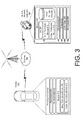
- FIG. 3 depicts system or architecture in which techniques for processing image information and activating/deactivating an airbag deployment device may be implemented in accordance with the disclosure.
- a vehicle 302 may include a processor device 304.
- the processor device 304 may be configured to communicate with a service provider computer 306 via a network 308, or via other network connections.
- the processor device 304 or the service provider computer 306 may be configured to process an image received from a camera associated with the airbag deployment system and provide instructions for turning on or off the airbag deployment device.
- the processor device 304 may be any type of computing device capable of performing the described functions.
- the processor device 304 may include one or more processors 310 capable of processing input from one or more input sensors 312.
- input sensors 312 capable of detecting input related to a user or vehicle conditions, such as accelerometers, cameras, microphones, etc.
- the input obtained by the input sensors may be from a variety of data input types, including, but not limited to, audio data, visual data, or biometric data.
- Programmatic code for an application or module utilized in the implementation of at least some embodiments may be stored and executed from the memory 314 of processor device 304.
- the processor device 304 may include a module for processing image information to determine a viewer position (image processing module 316) and/or a module for implementing one or more facial recognition techniques (facial recognition module 318).
- the network(s) 308 may include any one or a combination of many different types of networks, such as cable networks, the Internet, wireless networks, cellular networks, and other private and/or public networks. It is also noted that the described techniques may apply in other client/server arrangements, as well as in non-client/server arrangements (e.g., locally stored applications, peer to-peer systems, etc.).
- the processor device 304 may communicate with a network hub using one or more wireless communication networks (e.g., 3G, 4G, etc.).
- the network hub may, in turn, utilize a physical connection (e.g., copper cable, T1, Ethernet, etc.) to communicate with the service provider computer at a network address.
- the service provider computer 306 may be any type of computing device such as, but not limited to, a mobile phone, a smart phone, a personal digital assistant (PDA), a laptop computer, a desktop computer, a server computer, a thin-client device, a tablet PC, etc. Additionally, it should be noted that, in some embodiments, the service provider computer 306 may be executed by one or more virtual machines implemented in a hosted computing environment.
- the hosted computing environment may include one or more rapidly provisioned and released computing resources, which computing resources may include computing, networking, and/or storage devices.
- a hosted computing environment may also be referred to as a cloud-computing environment.
- the service provider computer 306 may include at least one memory 320 and one or more processing units (or processor(s)) 322.
- the processor(s) 322 may be implemented as appropriate in hardware, computer-executable instructions, firmware or combinations thereof.
- Computer-executable instruction or firmware implementations of the processor(s) 322 may include computer-executable or machine executable instructions written in any suitable programming language to perform the various functions described.
- the memory 320 may store program instructions that are loadable and executable on the processor(s)310 and/or processor(s) 322, as well as data generated during the execution of these programs.
- the memory 320 may be volatile (such as random access memory (RAM)) and/or non-volatile (such as read-only memory (ROM), flash memory, etc.).
- the service provider computer 306 may also include additional storage 324, such as either removable storage or non-removable storage including, but not limited to, magnetic storage, optical disks, and/or tape storage.
- the disk drives and their associated computer-readable media may provide non-volatile storage of computer-readable instructions, data structures, program modules, and other data for the computing devices.
- the memory 320 may include multiple different types of memory, such as static random access memory (SRAM), dynamic random access memory (DRAM) or ROM.
- the memory 320 may include an operating system 326 and one or more application programs or services for implementing the features disclosed herein including at least a module for processing image information to determine a viewer position (image processing module 316) and/or a module for implementing one or more facial recognition techniques (facial recognition module 318.
- the memory 320 may also include pattern data 330, which provides data related to identifying portions of image information. In some embodiments, the pattern data 330 may be stored in a database.
- the memory 320 and the additional storage 324 are examples of computer-readable storage media.
- computer-readable storage media may include volatile or non-volatile, removable or non-removable media implemented in any method or technology for storage of information such as computer-readable instructions, data structures, program modules or other data.
- modules may refer to programming modules executed by computing systems (e.g., processors) that are part of the processor device 304 or the service provider computer 306.
- the service provider computer 306 may also contain communications connection(s) 330 that allow the service provider computer 306 to communicate with a stored database, another computing device or server, user terminals, and/or other devices on the network(s) 308.
- the service provider computer 306 may also include input/output (I/O) device(s) and/or ports 332, such as for enabling connection with a keyboard, a mouse, a pen, a voice input device, a touch input device, a display, speakers, a printer, etc.
- I/O input/output
- the memory 320 may include an operating system 326, a database containing pattern data 330 and the one or more application programs or services for implementing the features disclosed herein, including an image processing module 316 and/or a facial recognition module 318.
- the image processing module 316 may be configured to receive image information from one or more input sensors and identify a viewer position from the image information.
- the image processing module 316 may receive, as input, a digital image (or link to a digital image) and may provide, as output, a set of coordinates.
- the image processing module 316 may utilize one or more image processing techniques in order to identify image patterns within the received image that correspond to an eye or eyes. In the case that two eyes are identified, the image processing module 316 may output coordinates located halfway between both eyes. In the case that a single eye is identified, the image processing module 316 may output the coordinates of the identified eye. In the case that more than two eyes are identified, the image processing module 316 may return an error or determine the set of eyes that are most likely correct. For example, the image processing module 316 may determine a particular set of eyes is likely the correct set of eyes based on the position and/or orientation of each eye.
- the facial recognition module 318 may be configured to receive image information from one or more input sensors and identify a person from the image information. Once the person has been identified, a profile for that person may be retrieved from a profile data store to determine the person's age. The processor device 304 or service provider computer 306 may then determine whether the person's age is below an age threshold for activating the airbag deployment device of the airbag system, and may subsequently transmit a signal to activate or deactivate the airbag deployment device based on this determination.
- the person's profile information may include an indication that the person suffers from a medical condition that makes airbag deployment dangerous. The processor device 304 or service provider computer 306 may also transmit a signal to activate or deactivate the airbag deployment device based on this determination.
- the image processing module 316 and/or the facial recognition module 318 may be located on, and executed from, the memory 314 of the processor device 304.
- the instructions for activating or deactivating the airbag deployment device may be transmitted to the vehicle and executed by the airbag deployment system.
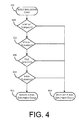
- FIG. 4 depicts an illustrative flow chart demonstrating an example automatic airbag deployment system on/off switch in accordance with at least some embodiments.
- the process 400 is illustrated as a logical flow diagram, each operation of which represents a sequence of operations that can be implemented in hardware, computer instructions, or a combination thereof.
- the operations represent computer-executable instructions stored on one or more computer-readable storage media that, when executed by one or more processors, perform the recited operations.
- computer-executable instructions include routines, programs, objects, components, data structures, and the like that perform particular functions or implement particular data types.
- the order in which the operations are described is not intended to be construed as a limitation, and any number of the described operations can be omitted or combined in any order and/or in parallel to implement this process and any other processes described herein.
- process 400 may be performed under the control of one or more computer systems configured with executable instructions and may be implemented as code (e.g., executable instructions, one or more computer programs or one or more applications).
- code e.g., executable instructions, one or more computer programs or one or more applications.
- the process 400 of FIG. 4 may be performed by at least the one or more service provider computers 306 and/or the processor device 304 shown in FIG. 3 .
- the code may be stored on a computer-readable storage medium, for example, in the form of a computer program including a plurality of instructions executable by one or more processors.
- the computer-readable storage medium may be non-transitory.
- Process 400 may begin at 402, when an initialization event is detected. For example, the process 400 may detect a startup of the car's engine, a buckling of a safety belt, a closing of a door, or the activation of a weight sensor in a vehicle seat. Upon detecting the initialization event, the process 400 may determine whether the object situated in the vehicle seat is a person meeting each of the threshold requirements to activate the airbag deployment device. It should be noted that although some orders for performing the activation threshold comparisons described will make more logical sense than others, each of the following activation threshold comparisons may be made in any order. Additionally, it should be noted that some embodiments of the disclosure will not include every activation threshold comparison described with respect to FIG. 4 .
- the process 400 may compare the weight of the object placed into the vehicle seat against a threshold weight at 404.
- activation threshold comparison 404 of the process 400 may be performed using a weight sensor, or a pressure sensor.
- one or more load cells located in the vehicle seat may produce an electrical signal whose magnitude is directly proportional to the pressure applied to the vehicle seat.
- the electrical signal may be provided to a comparator circuit to determine whether the electrical signal is greater than a threshold signal.
- the magnitude of the electrical signal may be compared to a threshold value by the processor device. If the magnitude of the electrical signal is greater than the threshold value, then the process 400 may determine that the weight activation threshold comparison is a success.
- the process 400 may compare the height of the object placed into the vehicle seat against a threshold height at 406.
- activation threshold comparison 406 of the process 400 may be performed using any device configured to detect a height of an object.
- the process 400 may utilize a pyroelectric sensor, or other sensor, capable of detecting infrared rays emitted from a living body.
- the pyroelectric sensors may be installed on the ceiling of the vehicle to detect the height of the object by determining a distance of the object from the ceiling.
- the process 400 may utilize a light beam emitted across a space occupied by an object in the vehicle seat at the height threshold.
- the process 400 may determine that the height threshold has been met.
- the process 400 may utilize a camera device to capture image information related to the object in the vehicle seat.
- a processor device may utilize one or more image processing techniques to determine the height of the object based on the image information. If the height of the object is met or exceeded, then the process 400 may determine that the height activation threshold comparison is a success.
- the process 400 may attempt to detect a face from image information captured with respect to the object situated in the vehicle seat at 408.
- the process 400 may utilize a camera device to capture image information related to the object in the vehicle seat.
- a processor device may utilize one or more facial recognition techniques to identify a facial structure in the captured image information.
- the process 400 may identify the person based on data produced using the facial recognition technique.
- the process 400 may only determine if a face is present in the captured image, and may not attempt to determine an identity of the person in the image. If the process 400 detects a face, then the process 400 may determine that the object situated in the vehicle seat is a person and may consider the activation threshold at 408 a success.
- the process 400 may compare the age of the person situated in the vehicle seat against a threshold age at 410.
- the processor device may use one or more facial recognition techniques to determine an age of a person seated in the vehicle seat.
- the process 400 may determine an identity of the person seated in the vehicle seat and may identify a user profile associated with that person.
- the user profile may include one or more details related to the person, including an indication of the person's age or date of birth.
- the profile data may be used to determine whether the person seated in the vehicle seat passes an age activation threshold comparison.
- a personal profile may include an indication of whether or not to activate an airbag deployment device of the airbag deployment system. For example, even if a person meets or exceeds each of the activation threshold comparisons presented in process 400, the airbag deployment device may still be deactivated if the profile information includes a configuration setting to deactivate the airbag deployment device. For example, the person may have a medical condition that makes deployment of an airbag dangerous. The person's profile may therefore indicate that the airbag is to be deactivated. Upon identifying the person, using facial recognition techniques, the airbag deployment system may access the person's profile and subsequently deactivate the airbag deployment device in response to determining that the airbag should not be deployed.
- an airbag deployment device may be activated, or turned on, at 412. If one or more of the activation threshold comparisons have been failed, then it may be unsafe or unnecessary to activate the airbag deployment device. In that case, the airbag deployment device may be deactivated, or turned off, at 414. It should be noted that the airbag deployment device may be placed in either an activated state or a deactivated state as a default state. For example, the airbag deployment device may begin in a deactivated state. In this example, the airbag deployment device may be activated only upon each of the activation threshold comparisons of process 400 successfully being made. In another example, the airbag deployment device may begin in an activated state. As each of the activation threshold comparisons of process 400 are made, the process may deactivate the airbag deployment device upon any of the activation threshold comparisons being unsuccessful.
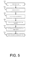
- FIG. 5 depicts an illustrative flow chart demonstrating an example process for providing instructions to an airbag deployment device in accordance with at least some embodiments.
- the process 500 is illustrated as a logical flow diagram, each operation of which represents a sequence of operations that can be implemented in hardware, computer instructions, or a combination thereof.
- the operations represent computer-executable instructions stored on one or more computer-readable storage media that, when executed by one or more processors, perform the recited operations.
- computer-executable instructions include routines, programs, objects, components, data structures, and the like that perform particular functions or implement particular data types.
- the order in which the operations are described is not intended to be construed as a limitation, and any number of the described operations can be omitted or combined in any order and/or in parallel to implement this process and any other processes described herein.
- process 500 may be performed under the control of one or more computer systems configured with executable instructions and may be implemented as code (e.g., executable instructions, one or more computer programs or one or more applications).
- code e.g., executable instructions, one or more computer programs or one or more applications.
- the process 500 of FIG. 5 may be performed by at least the one or more service provider computers 306 and/or the processor device 304 shown in FIG. 3 .
- the code may be stored on a computer-readable storage medium, for example, in the form of a computer program including a plurality of instructions executable by one or more processors.
- the computer-readable storage medium may be non-transitory.
- Process 500 may begin at 502, when an object is detected as being situated in a vehicle seat.
- the object may be detecting using one or more weight sensors attached to the vehicle seat. For example, the process may determine that a weight of the object is above a threshold weight.
- the object may be detected when a seatbelt for the vehicle seat is buckled, or the vehicle seat is adjusted.
- one or more camera devices may be activated at 504. The camera device, in response to receiving the signal to become active, may capture image information related to the object in the seat. For example, the camera device may take a picture of the object. The image information may then be provided to the service provider computer and/or the processor device.
- the process 500 may utilize a facial recognition technique to identify one or more structures in the image information that matches an eye pattern structure in a data store. If the process 500 is unable to identify at least one facial feature, then the process 500 may determine that the object situated in the vehicle seat is not a person. Otherwise, the process 500 may identify at least one facial feature of the object from the image information and the location of that facial feature at 508. The process 500 may subsequently determine whether the location of the facial feature in the image information is above a height threshold at 510. For example, the camera device may be fixed in a particular location, such that an image captured by the camera device may be associated with a coordinate grid.
- the location of the at least one facial feature may be mapped to an x and y coordinate value.
- the process may determine whether the y value (a vertical position) of the mapped coordinates is greater than a value associated with the threshold value.
- the process 500 may provide instructions to the airbag deployment device at 512. If the process has determined that the image information fails to meet at least one condition (e.g., the weight of the object is below a threshold weight, no facial feature is detect in the image information, the location of a detected facial feature is below a height threshold, etc.), then the airbag deployment device may be provided with instructions to deactivate, or turn off. Otherwise, the airbag deployment device may be provided with instructions to activate, or turn on.
- at least one condition e.g., the weight of the object is below a threshold weight, no facial feature is detect in the image information, the location of a detected facial feature is below a height threshold, etc.
- Disjunctive language such as the phrase "at least one of X, Y, or Z," unless specifically stated otherwise, is intended to be understood within the context as used in general to present that an item, term, etc., may be either X, Y, or Z, or any combination thereof (e.g., X, Y, and/or Z). Thus, such disjunctive language is not generally intended to, and should not, imply that certain embodiments require at least one of X, at least one of Y, or at least one of Z to each be present.
Applications Claiming Priority (3)
| Application Number | Priority Date | Filing Date | Title |
|---|---|---|---|
| US14/935,443 US9446730B1 (en) | 2015-11-08 | 2015-11-08 | Automatic passenger airbag switch |
| US14/967,388 US9725061B2 (en) | 2015-11-08 | 2015-12-14 | Automatic passenger airbag switch |
| US15/219,942 US10358104B2 (en) | 2015-11-08 | 2016-07-26 | Automated passenger airbag switch |
Publications (2)
| Publication Number | Publication Date |
|---|---|
| EP3165408A1 true EP3165408A1 (de) | 2017-05-10 |
| EP3165408B1 EP3165408B1 (de) | 2018-10-03 |
Family
ID=57189965
Family Applications (1)
| Application Number | Title | Priority Date | Filing Date |
|---|---|---|---|
| EP16195427.6A Not-in-force EP3165408B1 (de) | 2015-11-08 | 2016-10-25 | Automatischer insassenairbagschalter |
Country Status (1)
| Country | Link |
|---|---|
| EP (1) | EP3165408B1 (de) |
Cited By (4)
| Publication number | Priority date | Publication date | Assignee | Title |
|---|---|---|---|---|
| WO2019121231A1 (de) * | 2017-12-21 | 2019-06-27 | Daimler Ag | Verfahren zum betrieb einer insassenschutzvorrichtung |
| EP3560770A1 (de) * | 2018-04-26 | 2019-10-30 | Aisin Seiki Kabushiki Kaisha | Insasseninformationsbestimmungsvorrichtung |
| DE102020106065A1 (de) | 2020-03-06 | 2021-09-09 | Bayerische Motoren Werke Aktiengesellschaft | System und Verfahren zur Einstellung von Fahrzeugfunktionen eines Fahrzeuges |
| DE112018007120B4 (de) | 2018-03-22 | 2022-03-10 | Mitsubishi Electric Corporation | Physis-Ermittlungseinrichtung und Physis-Ermittlungsverfahren |
Citations (6)
| Publication number | Priority date | Publication date | Assignee | Title |
|---|---|---|---|---|
| US20040153229A1 (en) * | 2002-09-11 | 2004-08-05 | Gokturk Salih Burak | System and method for providing intelligent airbag deployment |
| WO2004071816A1 (de) * | 2003-02-14 | 2004-08-26 | Daimlerchrysler Ag | Verfahren zur voreinstellung eines insassenschutzsystems eines fahrzeugs |
| US20070251749A1 (en) * | 1995-06-07 | 2007-11-01 | Automotive Technologies International, Inc. | Vehicular Seats with Weight Sensing Capability |
| US20120018989A1 (en) * | 2004-08-31 | 2012-01-26 | Automotive Technologies International, Inc. | Method for deploying a vehicular occupant protection system |
| EP2436549A1 (de) * | 2010-10-01 | 2012-04-04 | Volvo Car Corporation | Verbesserte Steuerung eines Fahrzeugs und Fahrzeugsicherheitssysteme |
| EP2743141A1 (de) * | 2012-12-12 | 2014-06-18 | Volvo Car Corporation | Steuerungsanordnung für ein Fahrzeug |
-
2016
- 2016-10-25 EP EP16195427.6A patent/EP3165408B1/de not_active Not-in-force
Patent Citations (6)
| Publication number | Priority date | Publication date | Assignee | Title |
|---|---|---|---|---|
| US20070251749A1 (en) * | 1995-06-07 | 2007-11-01 | Automotive Technologies International, Inc. | Vehicular Seats with Weight Sensing Capability |
| US20040153229A1 (en) * | 2002-09-11 | 2004-08-05 | Gokturk Salih Burak | System and method for providing intelligent airbag deployment |
| WO2004071816A1 (de) * | 2003-02-14 | 2004-08-26 | Daimlerchrysler Ag | Verfahren zur voreinstellung eines insassenschutzsystems eines fahrzeugs |
| US20120018989A1 (en) * | 2004-08-31 | 2012-01-26 | Automotive Technologies International, Inc. | Method for deploying a vehicular occupant protection system |
| EP2436549A1 (de) * | 2010-10-01 | 2012-04-04 | Volvo Car Corporation | Verbesserte Steuerung eines Fahrzeugs und Fahrzeugsicherheitssysteme |
| EP2743141A1 (de) * | 2012-12-12 | 2014-06-18 | Volvo Car Corporation | Steuerungsanordnung für ein Fahrzeug |
Cited By (6)
| Publication number | Priority date | Publication date | Assignee | Title |
|---|---|---|---|---|
| WO2019121231A1 (de) * | 2017-12-21 | 2019-06-27 | Daimler Ag | Verfahren zum betrieb einer insassenschutzvorrichtung |
| US11535184B2 (en) | 2017-12-21 | 2022-12-27 | Mercedes-Benz Group AG | Method for operating an occupant protection device |
| DE112018007120B4 (de) | 2018-03-22 | 2022-03-10 | Mitsubishi Electric Corporation | Physis-Ermittlungseinrichtung und Physis-Ermittlungsverfahren |
| EP3560770A1 (de) * | 2018-04-26 | 2019-10-30 | Aisin Seiki Kabushiki Kaisha | Insasseninformationsbestimmungsvorrichtung |
| US20190329671A1 (en) * | 2018-04-26 | 2019-10-31 | Aisin Seiki Kabushiki Kaisha | Occupant information determination apparatus |
| DE102020106065A1 (de) | 2020-03-06 | 2021-09-09 | Bayerische Motoren Werke Aktiengesellschaft | System und Verfahren zur Einstellung von Fahrzeugfunktionen eines Fahrzeuges |
Also Published As
| Publication number | Publication date |
|---|---|
| EP3165408B1 (de) | 2018-10-03 |
Similar Documents
| Publication | Publication Date | Title |
|---|---|---|
| US10358104B2 (en) | Automated passenger airbag switch | |
| EP3165408B1 (de) | Automatischer insassenairbagschalter | |
| EP3060434B1 (de) | Reaktion auf fahrzeuginterne umgebungsbedingungen | |
| US10115029B1 (en) | Automobile video camera for the detection of children, people or pets left in a vehicle | |
| EP3583485B1 (de) | Recheneffizienter menschenidentifizierender intelligenter assistenzcomputer | |
| KR20200124278A (ko) | 차량 내 인원의 위험 동작 인식 방법 및 장치, 전자 기기, 저장 매체 | |
| US9928404B2 (en) | Determination device, determination method, and non-transitory storage medium | |
| US8775015B2 (en) | Vehicle collision event announcing system and method | |
| US20170185078A1 (en) | Technologies for managing sensor malfunctions | |
| US10286781B2 (en) | Method for the automatic execution of at least one driving function of a motor vehicle | |
| US11641586B2 (en) | Mobile device location determination | |
| CN111845763A (zh) | 用于在自主驾驶期间确保驾驶员参与度的安全机构 | |
| US11216968B2 (en) | Face direction estimation device and face direction estimation method | |
| US11373447B2 (en) | Systems including image detection to inhibit vehicle operation | |
| US20210182617A1 (en) | System and method for detecting abnormal passenger behavior in autonomous vehicles | |
| CN112052770A (zh) | 用于疲劳检测的方法、装置、介质以及电子设备 | |
| KR20200056187A (ko) | 운전자의 부주의 경고 제어 장치 및 방법 | |
| KR102084329B1 (ko) | 차량 내 유아 모니터링 방법 및 시스템 | |
| US20240101128A1 (en) | Predicting and minimizing risks associated with vehicle usage contexts | |
| US20220161688A1 (en) | Methods and systems for activating a door lock in a vehicle | |
| GB2525654A (en) | Driver incident assistance system and method | |
| CN110751008B (zh) | 基于驾驶行为的处理方法、装置、设备和存储介质 | |
| CN111931734A (zh) | 识别遗落物体的方法、装置、车载终端和存储介质 | |
| KR20220009593A (ko) | 인공 지능을 활용한 차량 내 영유아 방치 상태의 알림 시스템 및 방법 | |
| CN117048446A (zh) | 座椅的调控方法及装置、车辆、电子设备和存储介质 |
Legal Events
| Date | Code | Title | Description |
|---|---|---|---|
| PUAI | Public reference made under article 153(3) epc to a published international application that has entered the european phase |
Free format text: ORIGINAL CODE: 0009012 |
|
| AK | Designated contracting states |
Kind code of ref document: A1 Designated state(s): AL AT BE BG CH CY CZ DE DK EE ES FI FR GB GR HR HU IE IS IT LI LT LU LV MC MK MT NL NO PL PT RO RS SE SI SK SM TR |
|
| AX | Request for extension of the european patent |
Extension state: BA ME |
|
| 17P | Request for examination filed |
Effective date: 20171026 |
|
| RBV | Designated contracting states (corrected) |
Designated state(s): AL AT BE BG CH CY CZ DE DK EE ES FI FR GB GR HR HU IE IS IT LI LT LU LV MC MK MT NL NO PL PT RO RS SE SI SK SM TR |
|
| GRAP | Despatch of communication of intention to grant a patent |
Free format text: ORIGINAL CODE: EPIDOSNIGR1 |
|
| RIC1 | Information provided on ipc code assigned before grant |
Ipc: B60R 21/015 20060101AFI20180313BHEP |
|
| INTG | Intention to grant announced |
Effective date: 20180416 |
|
| REG | Reference to a national code |
Ref country code: HK Ref legal event code: DE Ref document number: 1241328 Country of ref document: HK |
|
| GRAS | Grant fee paid |
Free format text: ORIGINAL CODE: EPIDOSNIGR3 |
|
| GRAA | (expected) grant |
Free format text: ORIGINAL CODE: 0009210 |
|
| AK | Designated contracting states |
Kind code of ref document: B1 Designated state(s): AL AT BE BG CH CY CZ DE DK EE ES FI FR GB GR HR HU IE IS IT LI LT LU LV MC MK MT NL NO PL PT RO RS SE SI SK SM TR |
|
| REG | Reference to a national code |
Ref country code: GB Ref legal event code: FG4D |
|
| REG | Reference to a national code |
Ref country code: CH Ref legal event code: EP Ref country code: AT Ref legal event code: REF Ref document number: 1048248 Country of ref document: AT Kind code of ref document: T Effective date: 20181015 |
|
| REG | Reference to a national code |
Ref country code: IE Ref legal event code: FG4D Ref country code: DE Ref legal event code: R096 Ref document number: 602016006199 Country of ref document: DE |
|
| PGFP | Annual fee paid to national office [announced via postgrant information from national office to epo] |
Ref country code: DE Payment date: 20181123 Year of fee payment: 3 |
|
| REG | Reference to a national code |
Ref country code: NL Ref legal event code: MP Effective date: 20181003 |
|
| REG | Reference to a national code |
Ref country code: LT Ref legal event code: MG4D Ref country code: NO Ref legal event code: T2 Effective date: 20181003 |
|
| PGFP | Annual fee paid to national office [announced via postgrant information from national office to epo] |
Ref country code: GB Payment date: 20181025 Year of fee payment: 13 Ref country code: FR Payment date: 20181130 Year of fee payment: 3 |
|
| REG | Reference to a national code |
Ref country code: ES Ref legal event code: FG2A Ref document number: 2702762 Country of ref document: ES Kind code of ref document: T3 Effective date: 20190305 |
|
| REG | Reference to a national code |
Ref country code: AT Ref legal event code: MK05 Ref document number: 1048248 Country of ref document: AT Kind code of ref document: T Effective date: 20181003 |
|
| PG25 | Lapsed in a contracting state [announced via postgrant information from national office to epo] |
Ref country code: NL Free format text: LAPSE BECAUSE OF FAILURE TO SUBMIT A TRANSLATION OF THE DESCRIPTION OR TO PAY THE FEE WITHIN THE PRESCRIBED TIME-LIMIT Effective date: 20181003 |
|
| PG25 | Lapsed in a contracting state [announced via postgrant information from national office to epo] |
Ref country code: PL Free format text: LAPSE BECAUSE OF FAILURE TO SUBMIT A TRANSLATION OF THE DESCRIPTION OR TO PAY THE FEE WITHIN THE PRESCRIBED TIME-LIMIT Effective date: 20181003 Ref country code: LV Free format text: LAPSE BECAUSE OF FAILURE TO SUBMIT A TRANSLATION OF THE DESCRIPTION OR TO PAY THE FEE WITHIN THE PRESCRIBED TIME-LIMIT Effective date: 20181003 Ref country code: HR Free format text: LAPSE BECAUSE OF FAILURE TO SUBMIT A TRANSLATION OF THE DESCRIPTION OR TO PAY THE FEE WITHIN THE PRESCRIBED TIME-LIMIT Effective date: 20181003 Ref country code: IS Free format text: LAPSE BECAUSE OF FAILURE TO SUBMIT A TRANSLATION OF THE DESCRIPTION OR TO PAY THE FEE WITHIN THE PRESCRIBED TIME-LIMIT Effective date: 20190203 Ref country code: BG Free format text: LAPSE BECAUSE OF FAILURE TO SUBMIT A TRANSLATION OF THE DESCRIPTION OR TO PAY THE FEE WITHIN THE PRESCRIBED TIME-LIMIT Effective date: 20190103 Ref country code: FI Free format text: LAPSE BECAUSE OF FAILURE TO SUBMIT A TRANSLATION OF THE DESCRIPTION OR TO PAY THE FEE WITHIN THE PRESCRIBED TIME-LIMIT Effective date: 20181003 Ref country code: LT Free format text: LAPSE BECAUSE OF FAILURE TO SUBMIT A TRANSLATION OF THE DESCRIPTION OR TO PAY THE FEE WITHIN THE PRESCRIBED TIME-LIMIT Effective date: 20181003 Ref country code: CZ Free format text: LAPSE BECAUSE OF FAILURE TO SUBMIT A TRANSLATION OF THE DESCRIPTION OR TO PAY THE FEE WITHIN THE PRESCRIBED TIME-LIMIT Effective date: 20181003 Ref country code: AT Free format text: LAPSE BECAUSE OF FAILURE TO SUBMIT A TRANSLATION OF THE DESCRIPTION OR TO PAY THE FEE WITHIN THE PRESCRIBED TIME-LIMIT Effective date: 20181003 |
|
| PGFP | Annual fee paid to national office [announced via postgrant information from national office to epo] |
Ref country code: NO Payment date: 20181127 Year of fee payment: 3 |
|
| PG25 | Lapsed in a contracting state [announced via postgrant information from national office to epo] |
Ref country code: SE Free format text: LAPSE BECAUSE OF FAILURE TO SUBMIT A TRANSLATION OF THE DESCRIPTION OR TO PAY THE FEE WITHIN THE PRESCRIBED TIME-LIMIT Effective date: 20181003 Ref country code: RS Free format text: LAPSE BECAUSE OF FAILURE TO SUBMIT A TRANSLATION OF THE DESCRIPTION OR TO PAY THE FEE WITHIN THE PRESCRIBED TIME-LIMIT Effective date: 20181003 Ref country code: GR Free format text: LAPSE BECAUSE OF FAILURE TO SUBMIT A TRANSLATION OF THE DESCRIPTION OR TO PAY THE FEE WITHIN THE PRESCRIBED TIME-LIMIT Effective date: 20190104 Ref country code: PT Free format text: LAPSE BECAUSE OF FAILURE TO SUBMIT A TRANSLATION OF THE DESCRIPTION OR TO PAY THE FEE WITHIN THE PRESCRIBED TIME-LIMIT Effective date: 20190203 Ref country code: AL Free format text: LAPSE BECAUSE OF FAILURE TO SUBMIT A TRANSLATION OF THE DESCRIPTION OR TO PAY THE FEE WITHIN THE PRESCRIBED TIME-LIMIT Effective date: 20181003 |
|
| REG | Reference to a national code |
Ref country code: BE Ref legal event code: MM Effective date: 20181031 |
|
| PG25 | Lapsed in a contracting state [announced via postgrant information from national office to epo] |
Ref country code: LU Free format text: LAPSE BECAUSE OF NON-PAYMENT OF DUE FEES Effective date: 20181025 |
|
| REG | Reference to a national code |
Ref country code: DE Ref legal event code: R097 Ref document number: 602016006199 Country of ref document: DE |
|
| REG | Reference to a national code |
Ref country code: IE Ref legal event code: MM4A |
|
| PG25 | Lapsed in a contracting state [announced via postgrant information from national office to epo] |
Ref country code: DK Free format text: LAPSE BECAUSE OF FAILURE TO SUBMIT A TRANSLATION OF THE DESCRIPTION OR TO PAY THE FEE WITHIN THE PRESCRIBED TIME-LIMIT Effective date: 20181003 |
|
| PLBE | No opposition filed within time limit |
Free format text: ORIGINAL CODE: 0009261 |
|
| STAA | Information on the status of an ep patent application or granted ep patent |
Free format text: STATUS: NO OPPOSITION FILED WITHIN TIME LIMIT |
|
| PG25 | Lapsed in a contracting state [announced via postgrant information from national office to epo] |
Ref country code: SK Free format text: LAPSE BECAUSE OF FAILURE TO SUBMIT A TRANSLATION OF THE DESCRIPTION OR TO PAY THE FEE WITHIN THE PRESCRIBED TIME-LIMIT Effective date: 20181003 Ref country code: RO Free format text: LAPSE BECAUSE OF FAILURE TO SUBMIT A TRANSLATION OF THE DESCRIPTION OR TO PAY THE FEE WITHIN THE PRESCRIBED TIME-LIMIT Effective date: 20181003 Ref country code: MC Free format text: LAPSE BECAUSE OF FAILURE TO SUBMIT A TRANSLATION OF THE DESCRIPTION OR TO PAY THE FEE WITHIN THE PRESCRIBED TIME-LIMIT Effective date: 20181003 Ref country code: BE Free format text: LAPSE BECAUSE OF NON-PAYMENT OF DUE FEES Effective date: 20181031 Ref country code: EE Free format text: LAPSE BECAUSE OF FAILURE TO SUBMIT A TRANSLATION OF THE DESCRIPTION OR TO PAY THE FEE WITHIN THE PRESCRIBED TIME-LIMIT Effective date: 20181003 Ref country code: SM Free format text: LAPSE BECAUSE OF FAILURE TO SUBMIT A TRANSLATION OF THE DESCRIPTION OR TO PAY THE FEE WITHIN THE PRESCRIBED TIME-LIMIT Effective date: 20181003 |
|
| 26N | No opposition filed |
Effective date: 20190704 |
|
| PG25 | Lapsed in a contracting state [announced via postgrant information from national office to epo] |
Ref country code: IE Free format text: LAPSE BECAUSE OF NON-PAYMENT OF DUE FEES Effective date: 20181025 Ref country code: SI Free format text: LAPSE BECAUSE OF FAILURE TO SUBMIT A TRANSLATION OF THE DESCRIPTION OR TO PAY THE FEE WITHIN THE PRESCRIBED TIME-LIMIT Effective date: 20181003 |
|
| PG25 | Lapsed in a contracting state [announced via postgrant information from national office to epo] |
Ref country code: MT Free format text: LAPSE BECAUSE OF NON-PAYMENT OF DUE FEES Effective date: 20181025 |
|
| PGFP | Annual fee paid to national office [announced via postgrant information from national office to epo] |
Ref country code: IT Payment date: 20191031 Year of fee payment: 4 |
|
| PG25 | Lapsed in a contracting state [announced via postgrant information from national office to epo] |
Ref country code: TR Free format text: LAPSE BECAUSE OF FAILURE TO SUBMIT A TRANSLATION OF THE DESCRIPTION OR TO PAY THE FEE WITHIN THE PRESCRIBED TIME-LIMIT Effective date: 20181003 |
|
| REG | Reference to a national code |
Ref country code: DE Ref legal event code: R119 Ref document number: 602016006199 Country of ref document: DE |
|
| REG | Reference to a national code |
Ref country code: NO Ref legal event code: MMEP |
|
| REG | Reference to a national code |
Ref country code: CH Ref legal event code: PL |
|
| PG25 | Lapsed in a contracting state [announced via postgrant information from national office to epo] |
Ref country code: CY Free format text: LAPSE BECAUSE OF FAILURE TO SUBMIT A TRANSLATION OF THE DESCRIPTION OR TO PAY THE FEE WITHIN THE PRESCRIBED TIME-LIMIT Effective date: 20181003 Ref country code: MK Free format text: LAPSE BECAUSE OF NON-PAYMENT OF DUE FEES Effective date: 20181003 Ref country code: HU Free format text: LAPSE BECAUSE OF FAILURE TO SUBMIT A TRANSLATION OF THE DESCRIPTION OR TO PAY THE FEE WITHIN THE PRESCRIBED TIME-LIMIT; INVALID AB INITIO Effective date: 20161025 |
|
| PG25 | Lapsed in a contracting state [announced via postgrant information from national office to epo] |
Ref country code: LI Free format text: LAPSE BECAUSE OF NON-PAYMENT OF DUE FEES Effective date: 20191031 Ref country code: CH Free format text: LAPSE BECAUSE OF NON-PAYMENT OF DUE FEES Effective date: 20191031 Ref country code: DE Free format text: LAPSE BECAUSE OF NON-PAYMENT OF DUE FEES Effective date: 20200501 Ref country code: NO Free format text: LAPSE BECAUSE OF NON-PAYMENT OF DUE FEES Effective date: 20191031 |
|
| PG25 | Lapsed in a contracting state [announced via postgrant information from national office to epo] |
Ref country code: FR Free format text: LAPSE BECAUSE OF NON-PAYMENT OF DUE FEES Effective date: 20191031 |
|
| REG | Reference to a national code |
Ref country code: ES Ref legal event code: FD2A Effective date: 20210226 |
|
| PG25 | Lapsed in a contracting state [announced via postgrant information from national office to epo] |
Ref country code: ES Free format text: LAPSE BECAUSE OF NON-PAYMENT OF DUE FEES Effective date: 20191026 |
|
| GBPC | Gb: european patent ceased through non-payment of renewal fee |
Effective date: 20201025 |
|
| PG25 | Lapsed in a contracting state [announced via postgrant information from national office to epo] |
Ref country code: GB Free format text: LAPSE BECAUSE OF NON-PAYMENT OF DUE FEES Effective date: 20201025 |
|
| PG25 | Lapsed in a contracting state [announced via postgrant information from national office to epo] |
Ref country code: IT Free format text: LAPSE BECAUSE OF NON-PAYMENT OF DUE FEES Effective date: 20201025 |