EP3165389B1 - Getriebe für ein kraftfahrzeug und antriebsstrang damit - Google Patents
Getriebe für ein kraftfahrzeug und antriebsstrang damit Download PDFInfo
- Publication number
- EP3165389B1 EP3165389B1 EP15192738.1A EP15192738A EP3165389B1 EP 3165389 B1 EP3165389 B1 EP 3165389B1 EP 15192738 A EP15192738 A EP 15192738A EP 3165389 B1 EP3165389 B1 EP 3165389B1
- Authority
- EP
- European Patent Office
- Prior art keywords
- transmission
- gear
- input shaft
- switching
- switching element
- Prior art date
- Legal status (The legal status is an assumption and is not a legal conclusion. Google has not performed a legal analysis and makes no representation as to the accuracy of the status listed.)
- Active
Links
- 230000005540 biological transmission Effects 0.000 title claims description 265
- 238000002485 combustion reaction Methods 0.000 claims description 57
- 230000002441 reversible effect Effects 0.000 claims description 23
- 230000008878 coupling Effects 0.000 claims description 12
- 238000010168 coupling process Methods 0.000 claims description 12
- 238000005859 coupling reaction Methods 0.000 claims description 12
- 239000007787 solid Substances 0.000 claims description 8
- 239000011159 matrix material Substances 0.000 description 18
- 230000001360 synchronised effect Effects 0.000 description 14
- 238000013519 translation Methods 0.000 description 13
- 230000014616 translation Effects 0.000 description 13
- 230000008901 benefit Effects 0.000 description 11
- 230000008859 change Effects 0.000 description 11
- 238000000034 method Methods 0.000 description 9
- 230000009467 reduction Effects 0.000 description 7
- 230000005520 electrodynamics Effects 0.000 description 6
- 230000007935 neutral effect Effects 0.000 description 5
- 238000010276 construction Methods 0.000 description 3
- 230000008569 process Effects 0.000 description 3
- 239000007858 starting material Substances 0.000 description 3
- 230000007704 transition Effects 0.000 description 3
- 230000001419 dependent effect Effects 0.000 description 2
- 238000013461 design Methods 0.000 description 2
- 238000011144 upstream manufacturing Methods 0.000 description 2
- 241001136792 Alle Species 0.000 description 1
- 208000012886 Vertigo Diseases 0.000 description 1
- 230000002411 adverse Effects 0.000 description 1
- 238000013459 approach Methods 0.000 description 1
- 210000000078 claw Anatomy 0.000 description 1
- 230000007423 decrease Effects 0.000 description 1
- 230000003993 interaction Effects 0.000 description 1
- 238000010248 power generation Methods 0.000 description 1
- 238000012546 transfer Methods 0.000 description 1
Images


Classifications
-
- B—PERFORMING OPERATIONS; TRANSPORTING
- B60—VEHICLES IN GENERAL
- B60K—ARRANGEMENT OR MOUNTING OF PROPULSION UNITS OR OF TRANSMISSIONS IN VEHICLES; ARRANGEMENT OR MOUNTING OF PLURAL DIVERSE PRIME-MOVERS IN VEHICLES; AUXILIARY DRIVES FOR VEHICLES; INSTRUMENTATION OR DASHBOARDS FOR VEHICLES; ARRANGEMENTS IN CONNECTION WITH COOLING, AIR INTAKE, GAS EXHAUST OR FUEL SUPPLY OF PROPULSION UNITS IN VEHICLES
- B60K6/00—Arrangement or mounting of plural diverse prime-movers for mutual or common propulsion, e.g. hybrid propulsion systems comprising electric motors and internal combustion engines ; Control systems therefor, i.e. systems controlling two or more prime movers, or controlling one of these prime movers and any of the transmission, drive or drive units Informative references: mechanical gearings with secondary electric drive F16H3/72; arrangements for handling mechanical energy structurally associated with the dynamo-electric machine H02K7/00; machines comprising structurally interrelated motor and generator parts H02K51/00; dynamo-electric machines not otherwise provided for in H02K see H02K99/00
- B60K6/20—Arrangement or mounting of plural diverse prime-movers for mutual or common propulsion, e.g. hybrid propulsion systems comprising electric motors and internal combustion engines ; Control systems therefor, i.e. systems controlling two or more prime movers, or controlling one of these prime movers and any of the transmission, drive or drive units Informative references: mechanical gearings with secondary electric drive F16H3/72; arrangements for handling mechanical energy structurally associated with the dynamo-electric machine H02K7/00; machines comprising structurally interrelated motor and generator parts H02K51/00; dynamo-electric machines not otherwise provided for in H02K see H02K99/00 the prime-movers consisting of electric motors and internal combustion engines, e.g. HEVs
- B60K6/22—Arrangement or mounting of plural diverse prime-movers for mutual or common propulsion, e.g. hybrid propulsion systems comprising electric motors and internal combustion engines ; Control systems therefor, i.e. systems controlling two or more prime movers, or controlling one of these prime movers and any of the transmission, drive or drive units Informative references: mechanical gearings with secondary electric drive F16H3/72; arrangements for handling mechanical energy structurally associated with the dynamo-electric machine H02K7/00; machines comprising structurally interrelated motor and generator parts H02K51/00; dynamo-electric machines not otherwise provided for in H02K see H02K99/00 the prime-movers consisting of electric motors and internal combustion engines, e.g. HEVs characterised by apparatus, components or means specially adapted for HEVs
- B60K6/36—Arrangement or mounting of plural diverse prime-movers for mutual or common propulsion, e.g. hybrid propulsion systems comprising electric motors and internal combustion engines ; Control systems therefor, i.e. systems controlling two or more prime movers, or controlling one of these prime movers and any of the transmission, drive or drive units Informative references: mechanical gearings with secondary electric drive F16H3/72; arrangements for handling mechanical energy structurally associated with the dynamo-electric machine H02K7/00; machines comprising structurally interrelated motor and generator parts H02K51/00; dynamo-electric machines not otherwise provided for in H02K see H02K99/00 the prime-movers consisting of electric motors and internal combustion engines, e.g. HEVs characterised by apparatus, components or means specially adapted for HEVs characterised by the transmission gearings
- B60K6/365—Arrangement or mounting of plural diverse prime-movers for mutual or common propulsion, e.g. hybrid propulsion systems comprising electric motors and internal combustion engines ; Control systems therefor, i.e. systems controlling two or more prime movers, or controlling one of these prime movers and any of the transmission, drive or drive units Informative references: mechanical gearings with secondary electric drive F16H3/72; arrangements for handling mechanical energy structurally associated with the dynamo-electric machine H02K7/00; machines comprising structurally interrelated motor and generator parts H02K51/00; dynamo-electric machines not otherwise provided for in H02K see H02K99/00 the prime-movers consisting of electric motors and internal combustion engines, e.g. HEVs characterised by apparatus, components or means specially adapted for HEVs characterised by the transmission gearings with the gears having orbital motion
-
- B—PERFORMING OPERATIONS; TRANSPORTING
- B60—VEHICLES IN GENERAL
- B60K—ARRANGEMENT OR MOUNTING OF PROPULSION UNITS OR OF TRANSMISSIONS IN VEHICLES; ARRANGEMENT OR MOUNTING OF PLURAL DIVERSE PRIME-MOVERS IN VEHICLES; AUXILIARY DRIVES FOR VEHICLES; INSTRUMENTATION OR DASHBOARDS FOR VEHICLES; ARRANGEMENTS IN CONNECTION WITH COOLING, AIR INTAKE, GAS EXHAUST OR FUEL SUPPLY OF PROPULSION UNITS IN VEHICLES
- B60K6/00—Arrangement or mounting of plural diverse prime-movers for mutual or common propulsion, e.g. hybrid propulsion systems comprising electric motors and internal combustion engines ; Control systems therefor, i.e. systems controlling two or more prime movers, or controlling one of these prime movers and any of the transmission, drive or drive units Informative references: mechanical gearings with secondary electric drive F16H3/72; arrangements for handling mechanical energy structurally associated with the dynamo-electric machine H02K7/00; machines comprising structurally interrelated motor and generator parts H02K51/00; dynamo-electric machines not otherwise provided for in H02K see H02K99/00
- B60K6/20—Arrangement or mounting of plural diverse prime-movers for mutual or common propulsion, e.g. hybrid propulsion systems comprising electric motors and internal combustion engines ; Control systems therefor, i.e. systems controlling two or more prime movers, or controlling one of these prime movers and any of the transmission, drive or drive units Informative references: mechanical gearings with secondary electric drive F16H3/72; arrangements for handling mechanical energy structurally associated with the dynamo-electric machine H02K7/00; machines comprising structurally interrelated motor and generator parts H02K51/00; dynamo-electric machines not otherwise provided for in H02K see H02K99/00 the prime-movers consisting of electric motors and internal combustion engines, e.g. HEVs
- B60K6/42—Arrangement or mounting of plural diverse prime-movers for mutual or common propulsion, e.g. hybrid propulsion systems comprising electric motors and internal combustion engines ; Control systems therefor, i.e. systems controlling two or more prime movers, or controlling one of these prime movers and any of the transmission, drive or drive units Informative references: mechanical gearings with secondary electric drive F16H3/72; arrangements for handling mechanical energy structurally associated with the dynamo-electric machine H02K7/00; machines comprising structurally interrelated motor and generator parts H02K51/00; dynamo-electric machines not otherwise provided for in H02K see H02K99/00 the prime-movers consisting of electric motors and internal combustion engines, e.g. HEVs characterised by the architecture of the hybrid electric vehicle
- B60K6/48—Parallel type
-
- B—PERFORMING OPERATIONS; TRANSPORTING
- B60—VEHICLES IN GENERAL
- B60K—ARRANGEMENT OR MOUNTING OF PROPULSION UNITS OR OF TRANSMISSIONS IN VEHICLES; ARRANGEMENT OR MOUNTING OF PLURAL DIVERSE PRIME-MOVERS IN VEHICLES; AUXILIARY DRIVES FOR VEHICLES; INSTRUMENTATION OR DASHBOARDS FOR VEHICLES; ARRANGEMENTS IN CONNECTION WITH COOLING, AIR INTAKE, GAS EXHAUST OR FUEL SUPPLY OF PROPULSION UNITS IN VEHICLES
- B60K6/00—Arrangement or mounting of plural diverse prime-movers for mutual or common propulsion, e.g. hybrid propulsion systems comprising electric motors and internal combustion engines ; Control systems therefor, i.e. systems controlling two or more prime movers, or controlling one of these prime movers and any of the transmission, drive or drive units Informative references: mechanical gearings with secondary electric drive F16H3/72; arrangements for handling mechanical energy structurally associated with the dynamo-electric machine H02K7/00; machines comprising structurally interrelated motor and generator parts H02K51/00; dynamo-electric machines not otherwise provided for in H02K see H02K99/00
- B60K6/20—Arrangement or mounting of plural diverse prime-movers for mutual or common propulsion, e.g. hybrid propulsion systems comprising electric motors and internal combustion engines ; Control systems therefor, i.e. systems controlling two or more prime movers, or controlling one of these prime movers and any of the transmission, drive or drive units Informative references: mechanical gearings with secondary electric drive F16H3/72; arrangements for handling mechanical energy structurally associated with the dynamo-electric machine H02K7/00; machines comprising structurally interrelated motor and generator parts H02K51/00; dynamo-electric machines not otherwise provided for in H02K see H02K99/00 the prime-movers consisting of electric motors and internal combustion engines, e.g. HEVs
- B60K6/50—Architecture of the driveline characterised by arrangement or kind of transmission units
- B60K6/54—Transmission for changing ratio
- B60K6/547—Transmission for changing ratio the transmission being a stepped gearing
-
- F—MECHANICAL ENGINEERING; LIGHTING; HEATING; WEAPONS; BLASTING
- F16—ENGINEERING ELEMENTS AND UNITS; GENERAL MEASURES FOR PRODUCING AND MAINTAINING EFFECTIVE FUNCTIONING OF MACHINES OR INSTALLATIONS; THERMAL INSULATION IN GENERAL
- F16H—GEARING
- F16H3/00—Toothed gearings for conveying rotary motion with variable gear ratio or for reversing rotary motion
- F16H3/006—Toothed gearings for conveying rotary motion with variable gear ratio or for reversing rotary motion power being selectively transmitted by either one of the parallel flow paths
-
- F—MECHANICAL ENGINEERING; LIGHTING; HEATING; WEAPONS; BLASTING
- F16—ENGINEERING ELEMENTS AND UNITS; GENERAL MEASURES FOR PRODUCING AND MAINTAINING EFFECTIVE FUNCTIONING OF MACHINES OR INSTALLATIONS; THERMAL INSULATION IN GENERAL
- F16H—GEARING
- F16H37/00—Combinations of mechanical gearings, not provided for in groups F16H1/00 - F16H35/00
- F16H37/02—Combinations of mechanical gearings, not provided for in groups F16H1/00 - F16H35/00 comprising essentially only toothed or friction gearings
- F16H37/04—Combinations of toothed gearings only
- F16H37/042—Combinations of toothed gearings only change gear transmissions in group arrangement
- F16H37/046—Combinations of toothed gearings only change gear transmissions in group arrangement with an additional planetary gear train, e.g. creep gear, overdrive
-
- F—MECHANICAL ENGINEERING; LIGHTING; HEATING; WEAPONS; BLASTING
- F16—ENGINEERING ELEMENTS AND UNITS; GENERAL MEASURES FOR PRODUCING AND MAINTAINING EFFECTIVE FUNCTIONING OF MACHINES OR INSTALLATIONS; THERMAL INSULATION IN GENERAL
- F16H—GEARING
- F16H37/00—Combinations of mechanical gearings, not provided for in groups F16H1/00 - F16H35/00
- F16H37/02—Combinations of mechanical gearings, not provided for in groups F16H1/00 - F16H35/00 comprising essentially only toothed or friction gearings
- F16H37/06—Combinations of mechanical gearings, not provided for in groups F16H1/00 - F16H35/00 comprising essentially only toothed or friction gearings with a plurality of driving or driven shafts; with arrangements for dividing torque between two or more intermediate shafts
- F16H37/065—Combinations of mechanical gearings, not provided for in groups F16H1/00 - F16H35/00 comprising essentially only toothed or friction gearings with a plurality of driving or driven shafts; with arrangements for dividing torque between two or more intermediate shafts with a plurality of driving or driven shafts
-
- B—PERFORMING OPERATIONS; TRANSPORTING
- B60—VEHICLES IN GENERAL
- B60K—ARRANGEMENT OR MOUNTING OF PROPULSION UNITS OR OF TRANSMISSIONS IN VEHICLES; ARRANGEMENT OR MOUNTING OF PLURAL DIVERSE PRIME-MOVERS IN VEHICLES; AUXILIARY DRIVES FOR VEHICLES; INSTRUMENTATION OR DASHBOARDS FOR VEHICLES; ARRANGEMENTS IN CONNECTION WITH COOLING, AIR INTAKE, GAS EXHAUST OR FUEL SUPPLY OF PROPULSION UNITS IN VEHICLES
- B60K6/00—Arrangement or mounting of plural diverse prime-movers for mutual or common propulsion, e.g. hybrid propulsion systems comprising electric motors and internal combustion engines ; Control systems therefor, i.e. systems controlling two or more prime movers, or controlling one of these prime movers and any of the transmission, drive or drive units Informative references: mechanical gearings with secondary electric drive F16H3/72; arrangements for handling mechanical energy structurally associated with the dynamo-electric machine H02K7/00; machines comprising structurally interrelated motor and generator parts H02K51/00; dynamo-electric machines not otherwise provided for in H02K see H02K99/00
- B60K6/20—Arrangement or mounting of plural diverse prime-movers for mutual or common propulsion, e.g. hybrid propulsion systems comprising electric motors and internal combustion engines ; Control systems therefor, i.e. systems controlling two or more prime movers, or controlling one of these prime movers and any of the transmission, drive or drive units Informative references: mechanical gearings with secondary electric drive F16H3/72; arrangements for handling mechanical energy structurally associated with the dynamo-electric machine H02K7/00; machines comprising structurally interrelated motor and generator parts H02K51/00; dynamo-electric machines not otherwise provided for in H02K see H02K99/00 the prime-movers consisting of electric motors and internal combustion engines, e.g. HEVs
- B60K6/42—Arrangement or mounting of plural diverse prime-movers for mutual or common propulsion, e.g. hybrid propulsion systems comprising electric motors and internal combustion engines ; Control systems therefor, i.e. systems controlling two or more prime movers, or controlling one of these prime movers and any of the transmission, drive or drive units Informative references: mechanical gearings with secondary electric drive F16H3/72; arrangements for handling mechanical energy structurally associated with the dynamo-electric machine H02K7/00; machines comprising structurally interrelated motor and generator parts H02K51/00; dynamo-electric machines not otherwise provided for in H02K see H02K99/00 the prime-movers consisting of electric motors and internal combustion engines, e.g. HEVs characterised by the architecture of the hybrid electric vehicle
- B60K6/48—Parallel type
- B60K2006/4825—Electric machine connected or connectable to gearbox input shaft
-
- B—PERFORMING OPERATIONS; TRANSPORTING
- B60—VEHICLES IN GENERAL
- B60K—ARRANGEMENT OR MOUNTING OF PROPULSION UNITS OR OF TRANSMISSIONS IN VEHICLES; ARRANGEMENT OR MOUNTING OF PLURAL DIVERSE PRIME-MOVERS IN VEHICLES; AUXILIARY DRIVES FOR VEHICLES; INSTRUMENTATION OR DASHBOARDS FOR VEHICLES; ARRANGEMENTS IN CONNECTION WITH COOLING, AIR INTAKE, GAS EXHAUST OR FUEL SUPPLY OF PROPULSION UNITS IN VEHICLES
- B60K6/00—Arrangement or mounting of plural diverse prime-movers for mutual or common propulsion, e.g. hybrid propulsion systems comprising electric motors and internal combustion engines ; Control systems therefor, i.e. systems controlling two or more prime movers, or controlling one of these prime movers and any of the transmission, drive or drive units Informative references: mechanical gearings with secondary electric drive F16H3/72; arrangements for handling mechanical energy structurally associated with the dynamo-electric machine H02K7/00; machines comprising structurally interrelated motor and generator parts H02K51/00; dynamo-electric machines not otherwise provided for in H02K see H02K99/00
- B60K6/20—Arrangement or mounting of plural diverse prime-movers for mutual or common propulsion, e.g. hybrid propulsion systems comprising electric motors and internal combustion engines ; Control systems therefor, i.e. systems controlling two or more prime movers, or controlling one of these prime movers and any of the transmission, drive or drive units Informative references: mechanical gearings with secondary electric drive F16H3/72; arrangements for handling mechanical energy structurally associated with the dynamo-electric machine H02K7/00; machines comprising structurally interrelated motor and generator parts H02K51/00; dynamo-electric machines not otherwise provided for in H02K see H02K99/00 the prime-movers consisting of electric motors and internal combustion engines, e.g. HEVs
- B60K6/50—Architecture of the driveline characterised by arrangement or kind of transmission units
- B60K6/54—Transmission for changing ratio
- B60K2006/541—Transmission for changing ratio without reverse ratio using instead electric reversing
-
- B—PERFORMING OPERATIONS; TRANSPORTING
- B60—VEHICLES IN GENERAL
- B60Y—INDEXING SCHEME RELATING TO ASPECTS CROSS-CUTTING VEHICLE TECHNOLOGY
- B60Y2200/00—Type of vehicle
- B60Y2200/90—Vehicles comprising electric prime movers
- B60Y2200/92—Hybrid vehicles
-
- F—MECHANICAL ENGINEERING; LIGHTING; HEATING; WEAPONS; BLASTING
- F16—ENGINEERING ELEMENTS AND UNITS; GENERAL MEASURES FOR PRODUCING AND MAINTAINING EFFECTIVE FUNCTIONING OF MACHINES OR INSTALLATIONS; THERMAL INSULATION IN GENERAL
- F16H—GEARING
- F16H2200/00—Transmissions for multiple ratios
- F16H2200/003—Transmissions for multiple ratios characterised by the number of forward speeds
- F16H2200/0069—Transmissions for multiple ratios characterised by the number of forward speeds the gear ratios comprising ten forward speeds
-
- F—MECHANICAL ENGINEERING; LIGHTING; HEATING; WEAPONS; BLASTING
- F16—ENGINEERING ELEMENTS AND UNITS; GENERAL MEASURES FOR PRODUCING AND MAINTAINING EFFECTIVE FUNCTIONING OF MACHINES OR INSTALLATIONS; THERMAL INSULATION IN GENERAL
- F16H—GEARING
- F16H2200/00—Transmissions for multiple ratios
- F16H2200/20—Transmissions using gears with orbital motion
- F16H2200/2002—Transmissions using gears with orbital motion characterised by the number of sets of orbital gears
- F16H2200/2007—Transmissions using gears with orbital motion characterised by the number of sets of orbital gears with two sets of orbital gears
-
- Y—GENERAL TAGGING OF NEW TECHNOLOGICAL DEVELOPMENTS; GENERAL TAGGING OF CROSS-SECTIONAL TECHNOLOGIES SPANNING OVER SEVERAL SECTIONS OF THE IPC; TECHNICAL SUBJECTS COVERED BY FORMER USPC CROSS-REFERENCE ART COLLECTIONS [XRACs] AND DIGESTS
- Y02—TECHNOLOGIES OR APPLICATIONS FOR MITIGATION OR ADAPTATION AGAINST CLIMATE CHANGE
- Y02T—CLIMATE CHANGE MITIGATION TECHNOLOGIES RELATED TO TRANSPORTATION
- Y02T10/00—Road transport of goods or passengers
- Y02T10/60—Other road transportation technologies with climate change mitigation effect
- Y02T10/62—Hybrid vehicles
Definitions
- the invention relates to a transmission for a motor vehicle and a drive train for a hybrid vehicle with such a transmission.
- a transmission referred to here in particular a multi-speed transmission, in which a plurality of gears, ie fixed gear ratios between two shafts of the transmission, are preferably automatically switched by switching elements.
- the switching elements are, for example, clutches or brakes.
- Such transmissions are used primarily in motor vehicles, in particular also in commercial vehicles, to adapt the rotational speed and torque output characteristics of the drive unit to the driving resistances of the vehicle in a suitable manner.
- Hybrid drives have two or more different drive sources, with drive trains with an internal combustion engine and one or more electric motors have largely prevailed as a parallel hybrid or mixed hybrid. These variants have a substantially parallel in the power flow arrangement of the engine and the electric drive and thus both a superposition of drive torque and a drive with purely internal combustion engine drive or purely electric motor drive possible.
- a hybrid drive with an automated transmission which comprises an internal combustion engine, which is drivingly connected to at least a first transmission input shaft, with an electric drive having at least one electric machine, which is drivingly connected to a second transmission input shaft, with at least one countershaft, with in several Radsatzebenen arranged idler gears and fixed wheels, with multiple gear shift devices and with a transmission output shaft.
- the two transmission input shafts are arranged coaxially to each other, and that a gear shift device in one of their switching positions the two transmission input shafts drivingly connects with each other, and switches in a different shift position a gear.
- a partial transmission coupling is possible, which couples the two input shafts, the hollow shaft and the solid shaft, without a gear is switched.
- a device for a drive train of a hybrid vehicle is known, with a the elements web, sun gear and ring gear having planetary gear, wherein a first element of these elements of the planetary gear of the fixed connection of a first transmission input shaft of a first partial transmission of a transmission is used, and wherein a second element of these elements the planetary gear of the fixed connection of an electric machine of a hybrid drive, with a first switching element, via which a third element of these elements of the planetary gear in a first switching position of the first switching element to a second transmission input shaft of a second partial transmission of the transmission, to which further comprises an internal combustion engine of the hybrid drive can be coupled, and in a second switching position of the first switching element on the housing side or the stator side can be connected, and with a second
- an automated group transmission is known, with a main gear designed in countershaft design, which has a main shaft and at least one countershaft, and with a main transmission upstream drive group, one, designed as a solid shaft input shaft with an internal combustion engine and an output shaft with a final drive is coupled, with an electric machine to the upstream group can be coupled via a planetary gear and connects a range group in the form of a planetary gear to the main transmission.
- the main transmission shows four forward gear and one reverse gear plane, as well as three shift elements.
- the first switching element of the Vorschalty can connect the first or the second gear plane of the split group with the running as a solid shaft input shaft.
- the transmission according to the invention comprises a main transmission comprising two parallel-connected partial transmissions, and an output shaft and two planetary transmissions having at least the elements of web, sun gear and ring gear.
- Each partial transmission in this case has a transmission input shaft, wherein a first transmission input shaft for a first partial transmission as a hollow shaft and a second transmission input shaft for a second partial transmission is designed as a solid shaft.
- a first planetary gear closes as a range group to the main transmission.
- a range group serves to double the number of gears of the main gearbox, whereby two ranges can be switched, one fast and one slow range.
- the transmission comprises a fifth switching element, which couples the ring gear of the range group either with an output shaft or fixed to the housing fixed.
- the main transmission includes first, second, third, fourth and fifth gear planes and first, second, third and fourth shifting elements.
- a second planetary gear is provided between an electric machine and the first transmission input shaft as a planetary stage.
- the fifth gear plane forms the output constant of the main transmission and can be coupled by means of the fourth switching element in one of its switching positions to the web of the range group.
- the electric machine can thus support the tensile force by the torque is transmitted directly from the countershaft via the output constant on the web of the range group and thus to the connected to the bridge of the range group output shaft, while the fifth switching element is load-free and switched can.
- Another advantage of this structure is that when driving in a direct gear, the speed of the countershaft can be lowered to reduce drag losses, for example, at the bearings and the seals.
- the fourth switching element connects in a first switching position, the fifth gear plane of the main gear, the output constant, with the main shaft.
- the countershaft is connected via the output constant of the main transmission with the main shaft and the sun of the planetary gear of the range group.
- the transmission may include a sixth double-acting switching element, which couples the second input shaft with the ring gear of the planetary stage in a first shift position and locks the ring gear of the planetary stage fixed to the housing in a second switching position.
- the planetary stage can act as a superposition gear.
- a drive of the second input shaft is connected to the ring gear of the planetary stage, the electric machine in the sun of the planetary gear and the bridge of the planetary gear on the first input shaft of the main transmission.
- the planetary stage acts as a fixed Vorübersky for the electrical Machine. As a result, the electric machine can be cost-effectively designed with less torque, but higher speed.
- the ring gear of the planetary stage can also be connected directly to the transmission housing, or a part of the housing. This also creates a fixed pretranslation of the electrical machine with the advantages mentioned above.
- the planetary gear of the transmission is connected so that the ring gear of the planetary gear is connected to the first transmission input shaft, the web of the planetary gear is fixed to the housing and the sun gear of the planetary gear is connected to the electric machine.
- the transmission in this case comprises a sixth single-acting switching element which, when actuated, connects the second transmission input shaft to the electric machine and the sun gear of the planetary stage.
- the electric drive in the forward gears turns backwards and via the planetary stage mechanical reverse gears for driving the second transmission input shaft are provided by means of the sixth switching element.
- Those gears, which are assigned to the first partial transmission or the first transmission input shaft, are then used as reverse gears with additional reduction by the planetary stage.
- the main gearbox includes at least one countershaft. However, it can also be designed as a power split two-countershaft transmission. All gears on the countershaft are designed as fixed wheels. In the embodiment with two countershafts, both countershafts are each carried out with a fixed wheel per wheel plane of the main transmission.
- the main gearbox is designed as a 5-speed gear set, with five wheel planes, with two partial transmissions and a partial gearbox coupling.
- the fifth wheel plane forms the output constant. All wheel planes are designed as forward gear levels and a reverse gear is generated by reversing the direction of rotation of the electric machine.
- the first partial transmission is associated with the first transmission input shaft, which is designed as a hollow shaft.
- the second partial transmission is associated with the second transmission input shaft, which is designed as a solid shaft.
- the second part transmission is also assigned a direct gear, in which the power flow is not performed on the countershaft or countershafts.
- the two partial transmissions can be coupled by one of the switching elements, so that in part the gears of the partial transmissions can be used by the respective other partial transmission. As a result, a coupling of the two drives is possible without causing a torque is passed to the output shaft.
- the two drives can be operated with different ratios. Thus, suitable operating points can be selected for both drives depending on the driving situation.
- the electric machine can also be partially or completely stand still to avoid zero load losses.
- All switching elements in the main gearbox are designed as unsynchronized claw switching element.
- All switching elements of the main gear and the first planetary gear, the range group are designed as double-acting switching elements, which means that they have two actuating directions in a first and in a second switching position. But they can also be brought into a third open switching position, a neutral position in which neither the first nor the second switching position is actuated and no components are connected by the switching element.
- the coupling of components of the transmission with the housing can also be implemented by the coupling with a housing-fixed component or a housing part or with another rotationally fixed component of the transmission.
- the transmission may be part of a drive train of a hybrid vehicle.
- the drive train according to the invention has, in addition to the transmission according to the invention an internal combustion engine as a second drive, and a connected to wheels of the hybrid vehicle axle drive, wherein the second transmission input shaft of the main transmission is constantly connected to the engine or is connectable and the output shaft of the transmission is drivingly connected to the axle drive.
- a separating clutch for the internal combustion engine can be used, but is not necessary for purely electric driving, since the second transmission input shaft can be decoupled by opening switching elements.
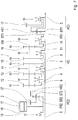
- Fig.1 shows a first embodiment of a transmission 1 with an electric machine 2, with a 5-speed main gear HG with two partial transmissions, with an output shaft 3, a first planetary gear PG1 and a second planetary gear PG2, each of the elements web ST1, ST2, at least a planetary gear PR1, PR2, sun gear SR1, SR2 and ring gear HR1, HR2 have.
- the first Planetary gear PG1 is used as a range group and connects to the main group HG.
- the second planetary gear PG2 is arranged as a planetary stage between the electric machine 2 and the first transmission input shaft 4.
- the first transmission input shaft 4 is designed as a hollow shaft and assigned to a first partial transmission of the main transmission HG.
- a second transmission input shaft 5 is designed as a solid shaft and associated with the second partial transmission of the main transmission HG.
- the main gear HG comprises a first gear plane R1, a second gear plane R2, a third gear plane R3, a fourth gear plane R4 and a fifth gear plane R5 and a first switching element S1, a second switching element S2, a third switching element S3 and a fourth switching element S4.
- the fifth gear plane R5 forms the output constant of the main transmission HG. All switching elements of the main transmission S1-S4 are designed as double-acting two-sided switching elements and can connect two different elements of the transmission 1 with a shaft or a transmission component.
- the first wheel plane R1 is formed by a first idler gear 6 of the first transmission input shaft 4 with a first fixed gear 12 of the countershaft VW.
- the second wheel plane R2 is formed by a loose wheel 7 of the first transmission input shaft 4 with a second fixed gear 13 of the countershaft VW.
- the third gear plane R3 is formed by a third idler gear 8 on the second transmission input shaft 5 and a third fixed gear 14 of the countershaft VW.
- the fourth gear plane R4 is formed by a fourth idler gear 9 on the second transmission input shaft 5 and a fourth fixed wheel 15 on the countershaft VW.
- the fifth gear plane R5 is formed by a fifth idler gear 11 on the main shaft 10 and a fifth fixed gear 16 on the countershaft VW.
- the main shaft 10 extends coaxially to the transmission input shaft 4, 5 and the output shaft 3 and lies between the second transmission input shaft 5 and the output shaft 3.
- the countershaft VW is parallel to the axis of the transmission input shafts 4, 5, the main shaft 10 and the output shaft 3. It can the first switching element S1 in a first switching position A connect the first gear plane R1 or in a second switching position B, the second gear plane R2 with the first transmission input shaft 4.
- the second switching element S2 can connect the first gear input shaft 4 in a first shift position C or the third gear plane R3 with the second transmission input shaft 5 in a second shift position D.
- the second switching element S2 thus serves in the first switching position C of the partial transmission coupling.
- the third switching element S3 can in a first switching position E the fourth gear plane R4 or in a second switching position F, the main shaft 10 with the second transmission input shaft 5 couple. In the second shift position F, a direct gear can thus be engaged, wherein torque is transmitted from the second transmission input shaft 5 via the main shaft 10 and the first planetary gear PG1 to the output shaft 3.
- the fourth shift element S4 can connect the main shaft 10 in a first shift position G or, in a second shift position H, the web ST1 of the first planetary gear set PG1 to the fifth wheel plane R5.
- the output constant, the fifth gear plane R5 of the main transmission HG, can thus be coupled via a single switching element, the fourth switching element S4, either to the sun SR1 or to the web ST1 of the first planetary gear PG1, since the main shaft 10 directly to the sun gear SR1 of first planetary gear is connected.
- the fifth switching element S5 is free of load and can be switched.
- the electrical machine 2 thus supports the tractive force via the countershaft VW, so that the range group PG1 can be switched with traction support.
- Another advantage of the coupling of the electric machine 2 to the web ST1 is that the speed of the countershaft VW can be lowered when driving in direct gear to reduce drag losses on bearings and seals.
- Each of the switching elements S1-S4 can also be switched to neutral so that it does not connect any of the elements mentioned.
- the transmission 1 comprises a range group in the form of a first planetary gear PG1.
- the range group PG1 serves to double the number of speeds of the main transmission HG.
- a fifth switching element S5 which is assigned to the range group PG1
- the ring gear HR1 of the first planetary gear PG1 are connected to a housing-fixed component 17 or a housing part or to another rotationally fixed component of the transmission 1. This creates a slow range.
- the ring gear HR1 of the first planetary gear PG1 can be connected to the output shaft 3 and thus also to the web ST1 of the first planetary gear PG1.
- the bridge ST1 is non-rotatable with connected to the output shaft 3.
- the components web ST1 and ring gear HR1 are locked together in the second switching position S of the switching element S5 and form a fast range.
- the second planetary gear PG2 is arranged as a planetary stage between an electric machine 2 and the first transmission input shaft 4.
- the electric machine 2 has a stator 18 which is non-rotatably connected to a housing-fixed component 17 or a transmission housing of the transmission 1 or with another non-rotatable component of the transmission 1, so that the stator 18 can not assume any speed.
- a rotatably mounted rotor 19 of the electric machine 2 is rotatably connected to a sun gear SR2 of the second planetary gear PG2 formed Planetenradsatzwelle the planetary stage PG2.
- the web ST2 of the second planetary gear PG2 is rotatably connected to the first transmission input shaft 4.
- the ring gear HR2 of the second planetary gear PG2 is connected via a sixth switching element S6, which is associated with the second planetary gear PG2, in a first switching position I to the second transmission input shaft 5 and fixed in a second switching position J of the sixth switching element S6 fixed to the housing.
- the planetary stage PG2 can act as a superposition gear.
- the planetary stage PG2 acts as a fixed pre-translation for the electric machine 2.
- the electric machine 2 can be designed cost-effectively with less torque, but a higher speed.
- the electric machine 2 is assigned to the first partial transmission.
- the second transmission input shaft 5 is also driven by a second drive, not shown here. Since this is usually an internal combustion engine 21, is spoken in the further document of an internal combustion engine 21 as a second drive.
- the internal combustion engine 21 is thus connected or connectable to the second partial transmission.
- Each partial transmission is also assigned switchable gears via the assigned wheel planes R1-R5.
- the first wheel plane R1 and the second wheel plane R2 of the main gear HG are the first Transmission input shaft 4 and thus also associated with the first partial transmission of the main transmission HG.
- a purely electric driving over the two gears is possible, which are formed over the two wheel planes R1 and R2.
- the range group PG1 produces four switchable purely electrical gears.
- the reverse drive is possible by reversing the direction of rotation of the electric machine 2.
- a separating clutch for the internal combustion engine 21 is not necessary for purely electric driving, since the second transmission input shaft 5 can be disconnected by opening the second and third switching element S2, S3.
- the third gear plane R3 and the fourth gear plane R4 of the main transmission HG are assigned to the second transmission input shaft 5 and thus also to the second part transmission of the main transmission HG.
- the fifth gear plane R5 serves as the output constant for both partial transmissions of the main transmission HG.
- the internal combustion engine 21 and the electric machine 2 can still use the gears of the respective other subtransmission.
- the second switching element S2 is designed as a double switching element, double-acting two-sided switching element, however, the electric machine 2 can not use the third gear plane R3 of the main transmission HG.
- internal combustion engine 21 and electric machine 2 can be operated with different ratios. In this way, suitable operating points can be selected for the internal combustion engine 21 and for the electric machine 2, depending on the driving situation.
- the electrical machine 2 can also be partially decoupled and stand still and thus avoid zero load losses. A decoupling of the electric machine 2 is possible via the first and the second switching element S1 and S2, which may not connect the first transmission input shaft 4 with another component, and the sixth switching element S6, which is not the ring gear HR2 of the planetary stage with the second transmission input shaft. 5 may couple.
- the internal combustion engine 21 can be connected to the electric machine 2, without a torque is conducted to the output shaft 3. At least the first switching elements S1 and the third switching element S3 of the main transmission HG are not actuated, but in a neutral position. As a result, the internal combustion engine 21 can be started with the electric machine 2, or it can be generated in neutral, that is to say independently of the driving speed, that is to say also when the machine is at a standstill. In this case, the internal combustion engine 21 drives the electric machine 2.
- the electric machine 2 operates as a generator.
- the Fig. 1 shows only the upper half of the axis of the transmission input shafts 4, 5, the main shaft 10 and the output shaft 3 symmetrical wheelset of the transmission 1.
- the reflection on this axis leads to a variant with two countershaft VW, which serve to power sharing.
- the wheelset is but functionally identical in the embodiment with only one countershaft VW. This means that the countershaft VW including the associated fixed wheels 12, 13, 14, 15, 16 are not mirrored.
- a start-up function known as EDA electrodynamic starting.
- the electric machine 2 can be used purely or only to support the internal combustion engine 21 for starting and accelerating.
- an increased starting torque can be provided via the second planetary gear PG2, which acts as a constant transmission.
- the sixth switching element S6 In order to approach electrodynamically, the sixth switching element S6 must be in its first switching position I.
- the transmission 1 is in the EDA mode.
- a gear of the first partial transmission which is assigned to the first transmission input shaft 4, must be inserted and the second partial transmission must be neutral, without transmission of torque.
- the first gear G1 of the transmission 1 is in Fig.
- the first wheel plane R1 is assigned to the first partial transmission.
- the first switching element S1 can be used in its first switching position A for electrodynamic starting and in the further power flow can be the first switching element S4 in its first switching position G and the fifth switching element S5 in its first switching position L for the first gear G1 first gear G1 a power flow from the first transmission input shaft 4 is prepared over the first wheel plane R1, the countershaft VW, the output constant R5, the main shaft 10 and the range group PG1 in the slow range.
- the internal combustion engine 21 rotates, for example, with the idling speed and the electric machine 2 rotates backwards, so that the web ST2 of the planetary stage PG2 is stationary.
- the torque ratios at the planetary stage PG2 are constant.
- the torque of the internal combustion engine 21 and the torque of the electric machine 2 add up to the web ST2 of the planetary stage PG2.
- the rotational speed of the electric machine 2 changes up to the block revolution at the planetary stage PG2.
- the start can be stopped by the second switching element S2 is brought into its first switching position C, and the planetary stage PG2 is blocked with it.
- EDA electrodynamic switching
- the sixth shift element S6 remains in its first shift position I.
- a gear assigned to the first subtransmission and thus to the first transmission input shaft 4 must be engaged.
- This serves as a support gear, over which the power flow is passed during the load circuit.
- the support gear can be identical to the current gear or a target gear.
- the switching process begins with a load transfer phase. In this case, the torques are set on the internal combustion engine 21 and on the electric machine 2 so that it corresponds to the stationary gear ratio of the planetary gear PG2.
- the EDS switching method has the advantage that the switching element of the target gear is synchronized by the interaction of the electric machine 2 and the internal combustion engine 21, the electric machine 2 being very easily controllable. Another advantage of the EDS switching process is that a high tensile force can be achieved, since the torques of the internal combustion engine 21 and the electric machine 2 add up to the second planetary gear PG2.
- Fig. 1 can also be implemented under ISG, Integrated Starter Generator, known function in which the internal combustion engine 21 can be started and accelerated via the electric machine 2 and the electric machine 2 can also be used as a generator.
- ISG mode the sixth switching element S6 is in its second switching position J and connects the ring gear HR2 with a housing-fixed component 17.
- ISG mode wherein the ring gear HR2 of the planetary gear PG2 is fixed to the housing fixed and the Electric machine 2 transmits a torque to the web ST2 of the planetary gear PG2.
- the Fig. 3 shows an associated switching matrix of the transmission 1 for the ten gears G1 - G10 from the viewpoint of the internal combustion engine 21 in the ISG mode.
- the sixth switching element S6 remains in its second switching position J.
- the gears G1 - G10 are listed in the first column. If the internal combustion engine 21 carries a power flow via the second partial transmission, via the solid shaft 5, then a gear can be preselected in the power-flow-free first partial transmission, via the hollow shaft 4, or the partial transmissions can be coupled.
- the preselection is behind the Gear number given in parenthesis.
- the second gear G2 for the internal combustion engine 21 is active
- the first gear G1 is preselected for the internal combustion engine 21 and at the same time already active for the electric machine 2.
- it is shown in the columns following the gears G1-G10 which shift elements S1-S6 are in which shift positions AJ.
- a cross x marks a closed switching position AJ.
- the power flow in first gear G1 becomes, as in Fig. 3 illustrated, via the second transmission input shaft 5, the second shift element S2 in its first shift position C, the first shift element S1 in its first shift position A, the first wheel plane R1, the countershaft VW, the output constant R5, the fourth shift element S4 in its first shift position G, the range group PG1 connected in the slow range is conducted to the output shaft 3.
- the power flow in the second gear G2 is via the second transmission input shaft 5, the second switching element S2 in its second switching position D, the third gear plane R3, the countershaft VW, the output constant R5, the fourth switching element S4 in its first switching position G, which is connected in the slow range Range group PG1 passed to the output shaft 3.
- both the first gear G1 and thus the first wheel plane R1 and also the second shift position B can be preselected for the fourth gear G4 and thus the second wheel plane R2.
- the preselected gears G1, G4 are assigned to the first partial transmission.
- the power flow in the third gear G3 is via the second transmission input shaft 5, the third switching element S3 in its first switching position E, the fourth gear plane R4, the countershaft VW, the output constant R5, the fourth switching element S4 in its first switching position G, which is connected in the slow range Range group PG1 passed to the output shaft 3.
- the fourth gear G4 and thus the second wheel plane R2 can be preselected.
- the power flow in the fourth gear G4 is via the second transmission input shaft 5, the second switching element S2 in its first shift position C, the first transmission input shaft 4, the first shift element S1 in its second shift position B, the second wheel plane R2, the countershaft VW, the output constant R5, the fourth shift element S4 in its first shift position G, passed in the slow range range group PG1 on the output shaft 3.
- the power flow in the fifth gear G5 is passed via the second transmission input shaft 5, the third shift element S3 in its second shift position F, the range group PG1 connected in the slow range to the output shaft 3.
- the fourth gear G4 can be preselected.
- the ninth gear G9 can be preselected.
- the sixth gear G6 can be preselected.
- the power flow in the sixth gear G6 is via the second transmission input shaft 5, the second shift element S2 in its first shift position C, the first transmission input shaft 4, the first shift element S1 in its first shift position A, the first wheel plane R1, the countershaft VW, the output constant R5 , the fourth switching element S4 in its second switching position H and passed over the switched into the fast range range group PG1 on the output shaft 3.
- the fifth switching element S5 is free of load, since it is bypassed by the power transmission via the web ST1 of the area group PG1 by the fourth switching element S4 in its second switching position H.
- the power flow in the seventh gear G7 is via the second transmission input shaft 5, the second switching element S2 in its second shift position D, the third wheel plane R3, the countershaft VW, the output constant R5, the fourth switching element S4 in its second switching position H and on in the passed fast range switched range group PG1 on the output shaft 3, wherein the fifth switching element S5 is still free of load.
- the sixth gear G6 can be preselected via the first shift element S1 in its first shift position A
- the ninth gear G9 can be preselected via the first shift element S1 in its second shift position B.
- the power flow in the eighth gear G8 is via the second transmission input shaft 5, the third switching element S3 in its first switching position E, the fourth gear plane R4, the countershaft VW, the output constant R5, the fourth switching element S4 in its second switching position H and passed over the switched into the fast range range group PG1 on the output shaft 3, wherein the fifth alternative switching element S5 is still free of load.
- the ninth gear G9 can be preselected via the first shift element S1 in its second shift position B.
- the power flow in ninth gear G9 is via the second transmission input shaft 5, the second switching element S2 in its first shift position C, the first transmission input shaft 4, the first shift element S1 in its second shift position B, the second wheel plane R2, the countershaft VW, the output constant R5 ,
- the fourth switching element S4 in its second switching position H and passed over the switched into the fast range range group PG1 on the output shaft 3, wherein the fifth switching element S5 is still free of load.
- the power flow in the tenth gear G10 is conducted to the output shaft 3 via the second transmission input shaft 5, the third shift element S3 in its second shift position F, the main shaft 10 and via the range group PG1 connected to the fast range.
- the second switching element S2 is switched in its first switching position C, since so the first transmission input shaft 4 at a defined speed, here the speed of the second transmission input shaft 5, is performed.
- the ninth gear G9 can be preselected, with the fifth shift element S5 being unloaded.
- the sixth gear G6 via the first shift element S1 in its first shift position A and the second shift element S2 in its first shift position C.
- the fourth switching element S4 must be open.
- the second switching element S2 must be open.
- the fifth switching element S5 could remain closed even in the first switching position L instead of in the second switching position S, since the fifth switching element S5 in both switching positions L and S is free of load when the power flow over the fourth switching element S4 in the second switching position H is passed directly to the web ST1 of the first planetary gear PG1. Due to the speed ratios at the range group PG1, however, it is advantageous to carry out the change from the first shift position L of the fifth shift element S5 to the second shift position S as early as possible.
- the traction-free switching of the range group PG1 usually takes place when changing from the fifth gear G5 to the sixth gear G6.
- the fifth gear G5 in ICG or hybrid driving in ISG mode this is connected via a direct gear in the slow range group PG1.
- the third switching element S3 is in its second switching position F and the fifth switching element is in its first switching position L. This is also in Fig. 3 in line G5 (4).
- the electrical machine 2 acts due to the history still in the fourth gear G4, wherein the first switching element S1 is in its second switching position B and the fourth switching element S4 in its first switching position G.
- the internal combustion engine 21 takes over the load.
- the fourth switching element S4 can be opened from the switching position G.
- the second switching position H of the fourth switching element S4 is actively synchronized via the speed control of the electric machine 2. For this purpose, the speed of the electric machine 2 must be lowered.
- the speed reduction is performed by the factor of the translation of the range group PG1, which in the numerical example Fig. 3 corresponds to the factor 3.713.
- the fourth switching element S4 can be switched without load in the second switching position H.
- the ninth gear G9 is preselected in this state, since the first switching element S1 is still in its second switching position B. This can now be opened without load.
- the first switching position A of the first switching element S1 is now synchronized actively via speed control of the electric machine 2.
- the speed of the electric machine 2 must be raised to the target speed level of the sixth gear G6.
- the speed increase takes place by the ratio of the gear ratio of the two gears, which are assigned to the first transmission input shaft.
- These are here the first and the fourth gear G1, G4, what a speed increase by the factor 1,3 / 0,592 2,2 (see Fig. 2 , first and second wheel plane R1, R2).
- the first switching element S1 can be brought without load in the switching position A, wherein at the same time the connection, the sixth gear G6, is preselected.
- the second shift position S can not be actively synchronized with the engine 21, because the engine 21, the speed can not drop far enough, since here the speed level of the tenth gear G10 (the third switching element S3 and the fifth switching element S5 respectively in the second switching position F and S), although sixth gear G6 is the target gear.
- the change from the first shift position L to the second shift position S of the fifth shift element S5 at this point is, as already mentioned, advantageous but not absolutely necessary.
- the change could also take place outside the circuit from the fifth gear G5 to the sixth gear G6 at a later time.
- the fifth switching element S5 would then initially remain in the first switching position L.
- the internal combustion engine 21 synchronizes to the target rotational speed of the sixth gear G6.
- the first switching position C of the second switching element is synchronized and can then be closed without load.
- the sixth gear G6 is engaged and completed the switching operation for the switching elements S1-S6.
- the load transition from the electric machine 2 to the internal combustion engine 21 can then take place depending on the operating strategy.
- both the fourth shift element S4 and the first shift element S1 must be switched over.
- first the fourth switching element S4 is changed and then only the first switching element S1.
- the electric machine 2 is first lowered in speed and can synchronize with high torque. Less energy is needed to change the rotational speed of the inertial mass of the rotor 19. If first the first switching element S1 would be switched, the rotational speed of the electric machine 2 would rise sharply in the meantime and there was the risk of overspeed, a low torque of the electric machine 2 at high speed.
- the process is independent of the pre-translation of the planetary stage PG2 for the electric machine 2. It is also without a planetary stage PG2, wherein the electric machine 2 and the rotor 19 would be connected directly to the first transmission input shaft 4.
- the sixth switching element S6 in the second switching position J is also closed for the ISG mode. It is driven by internal combustion engine, wherein the third switching element S3 is in its second switching position F.
- the fourth switching element S4 is due to its history in its second switching position H. This leads to that in the numerical example in Fig. 2 the rotational speed of the countershaft VW is higher by a factor of 2.197 than that of the internal combustion engine 21. This corresponds to the spur gear ratio i of the fifth gear plane R5.
- the sun gear SR1 and the land ST1 of the area group PG1 have identical rotational speeds because the area group PG1 is locked by the fifth shift element in its second shift position S.
- Lowering the speed of the Countershaft VW allows a better overall efficiency of the transmission 1 in the direct gear G10. Less speed means less drag losses or power loss at the bearings and seals. For this purpose, load-free switching elements can be closed. In the present wheel set, it is advantageous to bring the first switching element S1 into its first switching position A.
- the speed of the countershaft VW can also be lowered to zero. This drag losses would be avoided on the storage.
- the first high-speed gear shift element of the first sub-transmission is first closed, unless it is closed from its previous history. In the example illustrated here, this is the first shift element in the second shift position B, through which the fourth gear G4 is formed via the second wheel plane R2.
- the electric machine 2 itself does not reach a high speed level and therefore can synchronize faster. Also, no conventional syncs are charged.
- the Fig. 4 shows an associated switching matrix of the transmission 1 for the ten gears G1 - G10 from the viewpoint of the internal combustion engine 21 in the EDA mode.
- the sixth switching element S6 remains in its first switching position I. Otherwise, the switching matrix in the EDA mode is identical to the switching matrix in the ISG mode Fig. 3 , However, there are other speed ratios at the electric machine 2 and at the planetary stage PG2.
- the power interruption-free switching of the range group PG1 when changing from the fifth gear G5 to the sixth gear G6 can also be performed in the EDA mode.
- the sixth switching element S6 is always in its first shift position I.
- the third switching element S3 is in its second switching position F and the fifth switching element is in its first switching position L.
- This is also in Fig. 4 in line G5 (4).
- the electrical machine 2 acts due to the history still in the fourth gear G4, wherein the first switching element S1 is in its second switching position B and the fourth switching element S4 in its first switching position G.
- the fourth switching element S4 can be opened from the switching position G.
- the second switching position H of the fourth switching element S4 is actively synchronized via the speed control of the electric machine 2.
- the speed of the web ST2 of the planetary stage PG2 must be lowered, which is done by lowering the speed of the electric machine 2.
- the speed reduction on the web ST2 of the planetary stage PG2 is performed by the factor of the translation of the range group PG1, which in the numerical example Fig. 4 corresponds to the factor 3.713.
- the fourth switching element S4 can be switched without load in the second switching position H.
- the ninth gear G9 is preselected in this state, since the first switching element S1 is still in its second switching position B. This can now be opened without load.
- the first switching position A of the first switching element S1 is now synchronized actively via speed control of the electric machine 2.
- the speed of the web ST2 of the planetary stage PG2 must be raised by means of the electric machine 2 to the target speed level of the sixth gear G6.
- the speed increase takes place by the ratio of the gear ratio of the two gears, which are assigned to the first transmission input shaft.
- These are here the first and the fourth gear G1, G4, what a speed increase by the factor 1,3 / 0,592 2,2 (see Fig. 2 , first and second wheel plane R1, R2).
- the first switching element S1 can be placed without load in the first switching position A, wherein at the same time the connection gear, the sixth gear G6, is preselected.
- the torques of the engine 21 and the electric machine 2 are set to be in the ratio of the stationary gear ratio of the planetary stage PG2 so that the third switching element S3 to be designed becomes load-free.
- the power flow then runs exclusively through the web ST2 of the planetary stage PG2 on the target gear, the sixth gear G6, via the first switching element S1 in the first shift position A and the fourth shift element in the second shift position H.
- the second switching position F of the third switching element S3 is opened.
- the torques of the internal combustion engine 21 and the electric machine 2 are controlled so that the rotational speed of the internal combustion engine 21 decreases to the target rotational speed ,
- the first switching position C of the second switching element S2 synchronized and can then be closed without load.
- the sixth gear G6 is engaged and completed the switching operation for the switching elements S1-S6.
- the load transition from the electric machine 2 to the internal combustion engine 21 can then take place depending on the operating strategy.
- both the fourth switching element S4 and the first switching element S1 must be switched.
- first the fourth switching element S4 is changed and then only the first switching element S1.
- the electric machine 2 is first lowered in speed and can synchronize with high torque. Less energy is needed to change the rotational speed of the inertial mass of the rotor 19. If first the first switching element S1 would be switched, the rotational speed of the electric machine 2 would rise sharply in the meantime and there was the risk of overspeed, a low torque of the electric machine 2 at high speed.
- gear assignments there are other gear assignments conceivable in the main transmission HG.
- the second wheel plane R2 and the fourth wheel plane R4 can be reversed.
- the wheel planes for the third gear G3 and the fourth gear G4 would be reversed.
- a separating clutch or starting clutch for the internal combustion engine 21 may be added.
- one or more mechanical reverse gears can be added. This can be implemented either as an additional Stirnradebene with an additional switching element or planetary reversible kit with two additional switching elements, one forwards and one for backwards.
- a so-called GPR range group can be used, in which the reverse gear is integrated in the range group.
- the Fig. 5 shows a second embodiment of a 10-speed transmission according to the invention.
- the transmission 1 differs only in the embodiment of the second planetary gear PG2.
- the second planetary gear PG2 is also arranged as a planetary stage between an electric machine 2 and the first transmission input shaft 4.
- the electric machine 2 has a stator 18 which is non-rotatably connected to a housing-fixed component 17 or a transmission housing of the transmission 1 or with another non-rotatable component of the transmission 1, so that the stator 18 can not assume any speed.
- a rotatably mounted rotor 19 of the electric machine 2 is rotatably connected to a sun gear SR2 of the second planetary gear PG2 formed Planetenradsatzwelle the planetary stage.
- the web ST2 of the second planetary gear PG2 is rotatably connected to the first transmission input shaft 4.
- the ring gear HR2 of the second planetary gear PG2 is rotatably connected to a housing part 17.
- a fixed pre-translation for the electric machine 2 has the advantage that the electric machine 2 can be designed cost-effectively with less torque, but higher speed. Due to the arrangement of the electric machine 2 with the planetary stage on the first transmission input shaft 4, the electric machine 2 is further associated with the first partial transmission.
- the further construction of the transmission 1 corresponds to the first embodiment Fig. 1 ,
- the pretranslation by the planetary stage PG2 could also be completely eliminated.
- the electric machine 2 is then designed with less speed and more torque.
- gear assignments conceivable in the main transmission HG.
- the second wheel plane R2 and the fourth wheel plane R4 can be reversed.
- the wheel planes for the third gear G3 and the fourth gear G4 would be reversed.
- a separating clutch or starting clutch for the internal combustion engine 21 may be added.
- the second and the third switching element S2, S3 can be designed as a synchronized switching elements and the synchronization of the gears of the second partial transmission, the gears, which are associated with the second transmission input shaft 5, takes place with an open clutch.
- one or more mechanical reverse gears can be added. This can be implemented either as an additional Stirnradebene with an additional switching element or planetary reversible kit with two additional switching elements, one forwards and one for backwards.
- a so-called GPR range group can be used, in which the reverse gear is integrated in the range group.
- the Fig. 6 shows an associated switching matrix of the transmission 1 Fig. 5 for the ten gears G1 - G10 from the point of view of the internal combustion engine 21.
- This switching matrix essentially corresponds to the switching matrix Fig. 3 in the ISG mode, wherein the sixth switching element S6 is omitted, since the ring gear HR2 of the planetary stage PG2 permanently rotatably connected to a housing part.
- the power interruption-free switching of the range group PG1 and the method for lowering the countershaft speed in the direct gear, the tenth gear G10, are also performed as in the first variant in Fig. 1 ,
- the Fig. 7 shows a third embodiment of a 10-speed transmission according to the invention.
- the transmission 1 differs from the two previously indicated Embodiment variants only in the execution of the second planetary gear PG2.
- the second planetary gear PG2 is also arranged as a planetary stage between an electric machine 2 and the first transmission input shaft 4.
- the electric machine 2 has a stator 18 which is non-rotatably connected to a housing-fixed component 17 or a transmission housing of the transmission 1 or with another non-rotatable component of the transmission 1, so that the stator 18 can not assume any speed.
- a rotatably mounted rotor 19 of the electric machine 2 is rotatably connected to a sun gear SR2 of the second planetary gear PG2 formed Planetenradsatzwelle the planetary stage.
- the ring gear HR2 of the second planetary gear PG2 is rotatably connected to the first transmission input shaft 4.
- the web ST2 of the second planetary gear PG2 is rotatably connected to a housing part 17.
- the second planetary gear PG2 assigned a seventh switching element S7, which can connect the electric machine 2 and designed as a sun gear SR2 of the second planetary gear PG2 Planetenradsatzwelle the planetary stage with the second transmission input shaft 5.
- This seventh switching element S7 acts only on one side and can connect the second transmission input shaft 5 and the sun gear SR2 of the second planetary gear in the closed switching position R, or it can be open and make no connection between two components.
- a fixed pre-translation for the electric machine 2 has the advantage that the electric machine 2 can be designed cost-effectively with less torque, but higher speed.
- the electric machine 2 rotates in the forward gears backwards, which is easily possible in an electric machine 2.
- the gears that are associated with the first partial transmission, the gears of the first transmission input shaft 4 with the first and second wheel plane R1 and R2, are then used as reverse gears with additional reduction by the planetary gear PG2. Due to the arrangement of the electric machine 2 with the planetary stage on the first transmission input shaft 4, the electric machine 2 is further associated with the first partial transmission.
- the further construction of the transmission 1 corresponds to the first embodiment Fig. 1 ,
- the Fig. 8 shows an associated switching matrix of the transmission 1 Fig. 7 for the ten gears G1 - G10 and four reverse gears GR1 - GR4 from the point of view of the internal combustion engine 21.
- This switching matrix essentially corresponds to the switching matrix Fig. 3 , wherein the sixth switching element S6 is omitted and for a seventh switching element S7 was recorded with a switching position R.
- the power interruption-free switching of the range group PG1 and the method for synchronizing the countershaft speed in the direct gear, the tenth gear G10, are also performed as in the first variant in FIG Fig. 1 ,
- the power flow in the first reverse gear RG1 becomes, as in Fig. 8 illustrated, via the second transmission input shaft 5, the seventh shift element S7 in its shift position R, the second planetary gear PG2, the first transmission input shaft 4, the first shift element S1 in its first shift position A, the first wheel plane R1, the countershaft VW, the output constant R5 the Fourth switching element S4 in its first switching position G, the main shaft 10 and the range group PG1 connected in the slow range passed to the output shaft 3.
- the power flow in the second reverse gear RG2 is via the second transmission input shaft 5, the seventh switching element S7 in its shift position R, the second planetary gear PG2, the first transmission input shaft 4, the first shift element S1 in its second shift position B, the second wheel plane R2, the countershaft VW , the output constant R5, the fourth switching element S4 in its first switching position G, the main shaft 10 and the region in the slow range range group PG1 passed to the output shaft 3.
- the power flow in the third reverse gear RG3 is via the second transmission input shaft 5, the seventh switching element S7 in its shift position R, the second planetary gear PG2, the first transmission input shaft 4, the first shift element S1 in its first shift position A, the first wheel plane R1, the countershaft VW , the output constant R5, the fourth switching element S4 in its second switching position H and passed in the fast range range group PG1 directed to the output shaft 3.
- the power flow in the fourth reverse gear RG4 is via the second transmission input shaft 5, the seventh switching element S7 in its shift position R, the second planetary gear PG2, the first transmission input shaft 4, the first shift element S1 in its second shift position B, the second wheel plane R2, the countershaft VW, the output constant R5 the Fourth switching element S4 in its second switching position H and passed in the fast range range group PG1 passed to the output shaft 3.
- the transmission 1 may be part of a drive train 20 of a hybrid vehicle. This will be in Fig. 9 shown.
- the drive train 20 according to the invention comprises, in addition to the transmission 1 according to the invention an internal combustion engine 21 as a second drive, and connected to wheels 22 of the hybrid vehicle axle 23, wherein the second transmission input shaft 5 of the main transmission HG is continuously connected to the internal combustion engine 21 or connectable and the output shaft. 3 of the transmission 1 with the axle gear 23 is drivingly connected.
- a clutch for the internal combustion engine 21 can be installed between the engine 21 and the transmission 1, but is not necessary for purely electric driving, since the second transmission input shaft 5 can be decoupled as described by opening switching elements.
Landscapes
- Engineering & Computer Science (AREA)
- Mechanical Engineering (AREA)
- General Engineering & Computer Science (AREA)
- Chemical & Material Sciences (AREA)
- Combustion & Propulsion (AREA)
- Transportation (AREA)
- Structure Of Transmissions (AREA)
- Hybrid Electric Vehicles (AREA)
Priority Applications (4)
| Application Number | Priority Date | Filing Date | Title |
|---|---|---|---|
| EP15192738.1A EP3165389B1 (de) | 2015-11-03 | 2015-11-03 | Getriebe für ein kraftfahrzeug und antriebsstrang damit |
| US15/772,996 US10493838B2 (en) | 2015-11-03 | 2016-10-14 | Gearbox for a motor vehicle, and drivetrain having the same |
| CN201680066817.6A CN108290488B (zh) | 2015-11-03 | 2016-10-14 | 用于机动车辆的变速器和具有该变速器的动力总成 |
| PCT/EP2016/074680 WO2017076605A1 (de) | 2015-11-03 | 2016-10-14 | Getriebe für ein kraftfahrzeug und antriebsstrang damit |
Applications Claiming Priority (1)
| Application Number | Priority Date | Filing Date | Title |
|---|---|---|---|
| EP15192738.1A EP3165389B1 (de) | 2015-11-03 | 2015-11-03 | Getriebe für ein kraftfahrzeug und antriebsstrang damit |
Publications (2)
| Publication Number | Publication Date |
|---|---|
| EP3165389A1 EP3165389A1 (de) | 2017-05-10 |
| EP3165389B1 true EP3165389B1 (de) | 2018-12-26 |
Family
ID=54366071
Family Applications (1)
| Application Number | Title | Priority Date | Filing Date |
|---|---|---|---|
| EP15192738.1A Active EP3165389B1 (de) | 2015-11-03 | 2015-11-03 | Getriebe für ein kraftfahrzeug und antriebsstrang damit |
Country Status (4)
| Country | Link |
|---|---|
| US (1) | US10493838B2 (zh) |
| EP (1) | EP3165389B1 (zh) |
| CN (1) | CN108290488B (zh) |
| WO (1) | WO2017076605A1 (zh) |
Families Citing this family (5)
| Publication number | Priority date | Publication date | Assignee | Title |
|---|---|---|---|---|
| DE102015221493A1 (de) * | 2015-11-03 | 2017-05-04 | Zf Friedrichshafen Ag | Verfahren zum zugkraftunterbrechungsfreien Umschalten einer Bereichsgruppe |
| DE102017212859A1 (de) | 2017-07-26 | 2019-01-31 | Zf Friedrichshafen Ag | Verfahren zur Kompensation eines Abstützmoments am Verbrennungsmotor |
| DE102017007763B4 (de) * | 2017-08-16 | 2020-03-19 | Daimler Ag | Gruppengetriebevorrichtung |
| JP7372088B2 (ja) * | 2019-09-10 | 2023-10-31 | 株式会社Subaru | ハイブリッド車両システム |
| DE102019214689A1 (de) * | 2019-09-25 | 2021-03-25 | Zf Friedrichshafen Ag | Hybridgetriebe für ein Kraftfahrzeug |
Family Cites Families (31)
| Publication number | Priority date | Publication date | Assignee | Title |
|---|---|---|---|---|
| JP4323132B2 (ja) * | 2002-03-15 | 2009-09-02 | 株式会社日立製作所 | 自動車の制御方法,自動車の制御装置,変速機,変速機の制御装置および車両システム |
| DE102005043703A1 (de) | 2005-09-14 | 2007-03-15 | Daimlerchrysler Ag | Nutzfahrzeug mit einem Schaltklauengetriebe und einem Elektromotor |
| DE102008000953A1 (de) * | 2008-04-03 | 2009-10-08 | Zf Friedrichshafen Ag | Parallelhybridantriebsanordnung für ein Fahrzeug |
| DE102009046620A1 (de) | 2009-11-11 | 2011-05-19 | Zf Friedrichshafen Ag | Schaltvorrichtung und Verfahren zur Schaltsteuerung eines automatisierten Gruppengetriebes |
| DE102009054752A1 (de) | 2009-12-16 | 2011-06-22 | ZF Friedrichshafen AG, 88046 | Antriebsstrang mit einem automatisierten Gruppengetriebe |
| WO2011158882A1 (ja) | 2010-06-15 | 2011-12-22 | 本田技研工業株式会社 | ハイブリッド車両用駆動装置 |
| DE102010030573A1 (de) | 2010-06-28 | 2011-12-29 | Zf Friedrichshafen Ag | Hybridantrieb mit einem automatisierten Schaltgetriebe |
| DE102010030575A1 (de) | 2010-06-28 | 2011-12-29 | Zf Friedrichshafen Ag | Antriebsstrang mit einem automatisierten Gruppengetriebe |
| DE102010030571B4 (de) | 2010-06-28 | 2024-04-18 | Zf Friedrichshafen Ag | Automatisiertes Schaltgetriebe |
| DE102010061827A1 (de) | 2010-11-24 | 2012-05-24 | Zf Friedrichshafen Ag | Antriebsstrang und Verfahren zum Betreiben desselben |
| DE102010063582A1 (de) | 2010-12-20 | 2012-06-21 | Zf Friedrichshafen Ag | Vorrichtung für einen Antriebsstrang eines Hybridfahrzeugs, Antriebsstrang und Verfahren zum Betreiben derselben |
| DE102011005531B4 (de) | 2011-03-15 | 2023-12-14 | Zf Friedrichshafen Ag | Hybridantrieb eines Kraftfahrzeuges |
| DE102011080069A1 (de) * | 2011-07-29 | 2013-01-31 | Zf Friedrichshafen Ag | Automatisiertes Gruppengetriebe eines Kraftfahrzeugs und Verfahren zum Betreiben desselben |
| DE102013105785B4 (de) | 2012-06-18 | 2022-09-15 | Hyundai Motor Company | Leistungsübertragungsvorrichtung für ein Fahrzeug |
| DE102012213711A1 (de) * | 2012-08-02 | 2014-02-06 | Zf Friedrichshafen Ag | Getriebe für ein Kraftfahrzeug |
| DE102012217503A1 (de) | 2012-09-27 | 2014-03-27 | Zf Friedrichshafen Ag | Getriebe für ein Kraftfahrzeug |
| DE102012218367A1 (de) * | 2012-10-09 | 2014-04-24 | Zf Friedrichshafen Ag | Gruppengetriebevorrichtung mit einer elektrischen Maschine |
| DE102012220063A1 (de) | 2012-11-05 | 2014-05-08 | Zf Friedrichshafen Ag | Doppelkupplungsgetriebe in Vorgelegebauweise |
| DE102012220829A1 (de) * | 2012-11-15 | 2014-05-15 | Zf Friedrichshafen Ag | Verfahren zum Betreiben einer Antriebseinheit für ein Hybridfahrzeug |
| DE102012221889A1 (de) | 2012-11-29 | 2014-06-05 | Zf Friedrichshafen Ag | Zugkraftunterstütztes Mehrgruppengetriebe |
| DE102013200158A1 (de) | 2013-01-09 | 2014-07-10 | Zf Friedrichshafen Ag | Hybridantrieb für ein Kraftfahrzeug |
| DE102013202045A1 (de) * | 2013-02-07 | 2014-08-07 | Zf Friedrichshafen Ag | Gruppengetriebe eines Kraftfahrzeugs |
| DE102013211225A1 (de) * | 2013-06-17 | 2014-12-18 | Zf Friedrichshafen Ag | Hybridantriebsanordnung |
| DE102013211969A1 (de) | 2013-06-25 | 2015-01-08 | Zf Friedrichshafen Ag | Hybridantriebgetriebe in einem Kraftfahrzeugantriebsstrang und Verfahren zur Steuerung |
| DE102013222510B4 (de) | 2013-11-06 | 2020-07-09 | Zf Friedrichshafen Ag | Getriebe für ein Kraftfahrzeug sowie Verfahren zum Betreiben eines Getriebes |
| KR101588775B1 (ko) | 2013-12-31 | 2016-01-26 | 현대자동차 주식회사 | 차량용 변속장치 |
| DE102014202381A1 (de) | 2014-02-11 | 2015-08-13 | Zf Friedrichshafen Ag | Verfahren zum Betreiben einer Getriebeeinrichtung |
| SE539032C2 (sv) | 2014-03-20 | 2017-03-21 | Scania Cv Ab | Förfarande för att styra en hybriddrivlina, fordon med en sådan hybriddrivlina, datorprogram för att styra en sådan hybriddrivlina, samt en datorprogramprodukt innefattande programkod |
| US9989123B2 (en) | 2014-03-21 | 2018-06-05 | Eaton Cummins Automated Transmission Technologies Llc | Heavy duty transmission architecture |
| DE102014205275A1 (de) * | 2014-03-21 | 2015-09-24 | Zf Friedrichshafen Ag | Lastschaltgetriebe und Verfahren zum Betreiben desselben |
| SE539294C2 (sv) * | 2014-09-29 | 2017-06-20 | Scania Cv Ab | Förfarande för att styra en hybriddrivlina, fordon som innefattar en sådan hybriddrivlina, datorprogram för att styra ensådan hybriddrivlina, samt en datorprogramprodukt innefatta nde programkod |
-
2015
- 2015-11-03 EP EP15192738.1A patent/EP3165389B1/de active Active
-
2016
- 2016-10-14 CN CN201680066817.6A patent/CN108290488B/zh active Active
- 2016-10-14 WO PCT/EP2016/074680 patent/WO2017076605A1/de active Application Filing
- 2016-10-14 US US15/772,996 patent/US10493838B2/en active Active
Non-Patent Citations (1)
| Title |
|---|
| None * |
Also Published As
| Publication number | Publication date |
|---|---|
| US10493838B2 (en) | 2019-12-03 |
| US20180319265A1 (en) | 2018-11-08 |
| CN108290488A (zh) | 2018-07-17 |
| EP3165389A1 (de) | 2017-05-10 |
| WO2017076605A1 (de) | 2017-05-11 |
| CN108290488B (zh) | 2021-08-27 |
Similar Documents
| Publication | Publication Date | Title |
|---|---|---|
| EP3165388B1 (de) | Verfahren zur synchronisierung der vorgelegewellendrehzahl im direktgang | |
| EP2089639B1 (de) | Hybridantriebsstrang eines kraftfahrzeugs | |
| DE102013215114B4 (de) | Hybridantrieb eines Kraftfahrzeugs | |
| EP2920012B1 (de) | Verfahren zum betreiben einer antriebseinheit für ein hybridfahrzeug | |
| EP1972481A1 (de) | Verfahren zum Betrieb eines Hybridantriebssystems sowie Hybridsantriebssystem mit zwei Teilgetrieben | |
| DE102011080068A1 (de) | Automatisiertes Gruppengetriebe eines Kraftfahrzeugs und Verfahren zum Betreiben desselben | |
| DE102013221461A1 (de) | Hybridantrieb eines Kraftfahrzeugs | |
| WO2017108303A1 (de) | Getriebe eines kraftfahrzeugs und verfahren zum betreiben eines kraftfahrzeugs | |
| EP3165389B1 (de) | Getriebe für ein kraftfahrzeug und antriebsstrang damit | |
| DE102013211969A1 (de) | Hybridantriebgetriebe in einem Kraftfahrzeugantriebsstrang und Verfahren zur Steuerung | |
| WO2017076607A1 (de) | Antriebsanordnung für ein hybridfahrzeug und antriebsstrang mit einer solchen antriebsanordnung | |
| DE10013734A1 (de) | Automatisches Gruppen - Lastschaltgetriebe mit Synchronisations- und Lastschaltfunktion über eine Drehmaschine | |
| WO2017076606A1 (de) | Verfahren zum zugkraftunterbrechungsfreien umschalten einer bereichsgruppe | |
| WO2017076899A1 (de) | Getriebe für ein hybridfahrzeug, antriebsstrang mit einem solchen getriebe und verfahren zum betreiben desselben | |
| DE102015221490A1 (de) | Verfahren zur Synchronisierung der Vorgelegewellendrehzahl im Direktgang | |
| WO2020177893A1 (de) | Antriebsstrang für ein kraftfahrzeug sowie verfahren zum betreiben eines antriebsstranges | |
| DE102017222712B4 (de) | Getriebe für ein Kraftfahrzeug | |
| DE102016204580A1 (de) | Hybridantriebsstrang für ein hybridgetriebenes Kraftfahrzeug | |
| DE102015221487A1 (de) | Getriebe für ein Kraftfahrzeug | |
| DE102015226301A1 (de) | Getriebe für ein Kraftfahrzeug | |
| DE102017222717B4 (de) | Getriebe für ein Kraftfahrzeug | |
| DE102017222711B4 (de) | Getriebe für ein Kraftfahrzeug | |
| DE102017222724B4 (de) | Getriebe für ein Kraftfahrzeug | |
| DE102016204582A1 (de) | Hybridantriebsstrang für ein hybridgetriebenes Kraftfahrzeug | |
| DE102021206520B4 (de) | Gangvorwahlfrei lastschaltbares Hybridgetriebe mit einfachem Aufbau |
Legal Events
| Date | Code | Title | Description |
|---|---|---|---|
| PUAI | Public reference made under article 153(3) epc to a published international application that has entered the european phase |
Free format text: ORIGINAL CODE: 0009012 |
|
| STAA | Information on the status of an ep patent application or granted ep patent |
Free format text: STATUS: REQUEST FOR EXAMINATION WAS MADE |
|
| 17P | Request for examination filed |
Effective date: 20160815 |
|
| AK | Designated contracting states |
Kind code of ref document: A1 Designated state(s): AL AT BE BG CH CY CZ DE DK EE ES FI FR GB GR HR HU IE IS IT LI LT LU LV MC MK MT NL NO PL PT RO RS SE SI SK SM TR |
|
| AX | Request for extension of the european patent |
Extension state: BA ME |
|
| GRAP | Despatch of communication of intention to grant a patent |
Free format text: ORIGINAL CODE: EPIDOSNIGR1 |
|
| STAA | Information on the status of an ep patent application or granted ep patent |
Free format text: STATUS: GRANT OF PATENT IS INTENDED |
|
| INTG | Intention to grant announced |
Effective date: 20180702 |
|
| GRAS | Grant fee paid |
Free format text: ORIGINAL CODE: EPIDOSNIGR3 |
|
| GRAA | (expected) grant |
Free format text: ORIGINAL CODE: 0009210 |
|
| STAA | Information on the status of an ep patent application or granted ep patent |
Free format text: STATUS: THE PATENT HAS BEEN GRANTED |
|
| AK | Designated contracting states |
Kind code of ref document: B1 Designated state(s): AL AT BE BG CH CY CZ DE DK EE ES FI FR GB GR HR HU IE IS IT LI LT LU LV MC MK MT NL NO PL PT RO RS SE SI SK SM TR |
|
| REG | Reference to a national code |
Ref country code: GB Ref legal event code: FG4D Free format text: NOT ENGLISH |
|
| REG | Reference to a national code |
Ref country code: CH Ref legal event code: EP |
|
| REG | Reference to a national code |
Ref country code: AT Ref legal event code: REF Ref document number: 1080924 Country of ref document: AT Kind code of ref document: T Effective date: 20190115 |
|
| REG | Reference to a national code |
Ref country code: DE Ref legal event code: R096 Ref document number: 502015007410 Country of ref document: DE |
|
| REG | Reference to a national code |
Ref country code: IE Ref legal event code: FG4D Free format text: LANGUAGE OF EP DOCUMENT: GERMAN |
|
| REG | Reference to a national code |
Ref country code: CH Ref legal event code: PK Free format text: BERICHTIGUNGEN |
|
| RIC2 | Information provided on ipc code assigned after grant |
Ipc: B60K 6/365 20071001AFI20160303BHEP Ipc: B60K 6/48 20071001ALI20160303BHEP Ipc: F16H 37/04 20060101ALI20160303BHEP Ipc: B60K 6/547 20071001ALI20160303BHEP Ipc: F16H 3/00 20060101ALI20160303BHEP |
|
| PG25 | Lapsed in a contracting state [announced via postgrant information from national office to epo] |
Ref country code: LV Free format text: LAPSE BECAUSE OF FAILURE TO SUBMIT A TRANSLATION OF THE DESCRIPTION OR TO PAY THE FEE WITHIN THE PRESCRIBED TIME-LIMIT Effective date: 20181226 Ref country code: HR Free format text: LAPSE BECAUSE OF FAILURE TO SUBMIT A TRANSLATION OF THE DESCRIPTION OR TO PAY THE FEE WITHIN THE PRESCRIBED TIME-LIMIT Effective date: 20181226 Ref country code: NO Free format text: LAPSE BECAUSE OF FAILURE TO SUBMIT A TRANSLATION OF THE DESCRIPTION OR TO PAY THE FEE WITHIN THE PRESCRIBED TIME-LIMIT Effective date: 20190326 Ref country code: BG Free format text: LAPSE BECAUSE OF FAILURE TO SUBMIT A TRANSLATION OF THE DESCRIPTION OR TO PAY THE FEE WITHIN THE PRESCRIBED TIME-LIMIT Effective date: 20190326 Ref country code: LT Free format text: LAPSE BECAUSE OF FAILURE TO SUBMIT A TRANSLATION OF THE DESCRIPTION OR TO PAY THE FEE WITHIN THE PRESCRIBED TIME-LIMIT Effective date: 20181226 Ref country code: FI Free format text: LAPSE BECAUSE OF FAILURE TO SUBMIT A TRANSLATION OF THE DESCRIPTION OR TO PAY THE FEE WITHIN THE PRESCRIBED TIME-LIMIT Effective date: 20181226 |
|
| REG | Reference to a national code |
Ref country code: NL Ref legal event code: MP Effective date: 20181226 |
|
| REG | Reference to a national code |
Ref country code: LT Ref legal event code: MG4D |
|
| PG25 | Lapsed in a contracting state [announced via postgrant information from national office to epo] |
Ref country code: SE Free format text: LAPSE BECAUSE OF FAILURE TO SUBMIT A TRANSLATION OF THE DESCRIPTION OR TO PAY THE FEE WITHIN THE PRESCRIBED TIME-LIMIT Effective date: 20181226 Ref country code: AL Free format text: LAPSE BECAUSE OF FAILURE TO SUBMIT A TRANSLATION OF THE DESCRIPTION OR TO PAY THE FEE WITHIN THE PRESCRIBED TIME-LIMIT Effective date: 20181226 Ref country code: GR Free format text: LAPSE BECAUSE OF FAILURE TO SUBMIT A TRANSLATION OF THE DESCRIPTION OR TO PAY THE FEE WITHIN THE PRESCRIBED TIME-LIMIT Effective date: 20190327 Ref country code: RS Free format text: LAPSE BECAUSE OF FAILURE TO SUBMIT A TRANSLATION OF THE DESCRIPTION OR TO PAY THE FEE WITHIN THE PRESCRIBED TIME-LIMIT Effective date: 20181226 |
|
| PG25 | Lapsed in a contracting state [announced via postgrant information from national office to epo] |
Ref country code: NL Free format text: LAPSE BECAUSE OF FAILURE TO SUBMIT A TRANSLATION OF THE DESCRIPTION OR TO PAY THE FEE WITHIN THE PRESCRIBED TIME-LIMIT Effective date: 20181226 |
|
| PG25 | Lapsed in a contracting state [announced via postgrant information from national office to epo] |
Ref country code: PT Free format text: LAPSE BECAUSE OF FAILURE TO SUBMIT A TRANSLATION OF THE DESCRIPTION OR TO PAY THE FEE WITHIN THE PRESCRIBED TIME-LIMIT Effective date: 20190426 Ref country code: ES Free format text: LAPSE BECAUSE OF FAILURE TO SUBMIT A TRANSLATION OF THE DESCRIPTION OR TO PAY THE FEE WITHIN THE PRESCRIBED TIME-LIMIT Effective date: 20181226 Ref country code: CZ Free format text: LAPSE BECAUSE OF FAILURE TO SUBMIT A TRANSLATION OF THE DESCRIPTION OR TO PAY THE FEE WITHIN THE PRESCRIBED TIME-LIMIT Effective date: 20181226 Ref country code: IT Free format text: LAPSE BECAUSE OF FAILURE TO SUBMIT A TRANSLATION OF THE DESCRIPTION OR TO PAY THE FEE WITHIN THE PRESCRIBED TIME-LIMIT Effective date: 20181226 Ref country code: PL Free format text: LAPSE BECAUSE OF FAILURE TO SUBMIT A TRANSLATION OF THE DESCRIPTION OR TO PAY THE FEE WITHIN THE PRESCRIBED TIME-LIMIT Effective date: 20181226 |
|
| PG25 | Lapsed in a contracting state [announced via postgrant information from national office to epo] |
Ref country code: IS Free format text: LAPSE BECAUSE OF FAILURE TO SUBMIT A TRANSLATION OF THE DESCRIPTION OR TO PAY THE FEE WITHIN THE PRESCRIBED TIME-LIMIT Effective date: 20190426 Ref country code: SM Free format text: LAPSE BECAUSE OF FAILURE TO SUBMIT A TRANSLATION OF THE DESCRIPTION OR TO PAY THE FEE WITHIN THE PRESCRIBED TIME-LIMIT Effective date: 20181226 Ref country code: SK Free format text: LAPSE BECAUSE OF FAILURE TO SUBMIT A TRANSLATION OF THE DESCRIPTION OR TO PAY THE FEE WITHIN THE PRESCRIBED TIME-LIMIT Effective date: 20181226 Ref country code: RO Free format text: LAPSE BECAUSE OF FAILURE TO SUBMIT A TRANSLATION OF THE DESCRIPTION OR TO PAY THE FEE WITHIN THE PRESCRIBED TIME-LIMIT Effective date: 20181226 Ref country code: EE Free format text: LAPSE BECAUSE OF FAILURE TO SUBMIT A TRANSLATION OF THE DESCRIPTION OR TO PAY THE FEE WITHIN THE PRESCRIBED TIME-LIMIT Effective date: 20181226 |
|
| REG | Reference to a national code |
Ref country code: DE Ref legal event code: R097 Ref document number: 502015007410 Country of ref document: DE |
|
| PG25 | Lapsed in a contracting state [announced via postgrant information from national office to epo] |
Ref country code: DK Free format text: LAPSE BECAUSE OF FAILURE TO SUBMIT A TRANSLATION OF THE DESCRIPTION OR TO PAY THE FEE WITHIN THE PRESCRIBED TIME-LIMIT Effective date: 20181226 |
|
| PLBE | No opposition filed within time limit |
Free format text: ORIGINAL CODE: 0009261 |
|
| STAA | Information on the status of an ep patent application or granted ep patent |
Free format text: STATUS: NO OPPOSITION FILED WITHIN TIME LIMIT |
|
| 26N | No opposition filed |
Effective date: 20190927 |
|
| PG25 | Lapsed in a contracting state [announced via postgrant information from national office to epo] |
Ref country code: SI Free format text: LAPSE BECAUSE OF FAILURE TO SUBMIT A TRANSLATION OF THE DESCRIPTION OR TO PAY THE FEE WITHIN THE PRESCRIBED TIME-LIMIT Effective date: 20181226 |
|
| PG25 | Lapsed in a contracting state [announced via postgrant information from national office to epo] |
Ref country code: TR Free format text: LAPSE BECAUSE OF FAILURE TO SUBMIT A TRANSLATION OF THE DESCRIPTION OR TO PAY THE FEE WITHIN THE PRESCRIBED TIME-LIMIT Effective date: 20181226 |
|
| REG | Reference to a national code |
Ref country code: CH Ref legal event code: PL |
|
| PG25 | Lapsed in a contracting state [announced via postgrant information from national office to epo] |
Ref country code: CH Free format text: LAPSE BECAUSE OF NON-PAYMENT OF DUE FEES Effective date: 20191130 Ref country code: LU Free format text: LAPSE BECAUSE OF NON-PAYMENT OF DUE FEES Effective date: 20191103 Ref country code: MC Free format text: LAPSE BECAUSE OF FAILURE TO SUBMIT A TRANSLATION OF THE DESCRIPTION OR TO PAY THE FEE WITHIN THE PRESCRIBED TIME-LIMIT Effective date: 20181226 Ref country code: LI Free format text: LAPSE BECAUSE OF NON-PAYMENT OF DUE FEES Effective date: 20191130 |
|
| REG | Reference to a national code |
Ref country code: BE Ref legal event code: MM Effective date: 20191130 |
|
| GBPC | Gb: european patent ceased through non-payment of renewal fee |
Effective date: 20191103 |
|
| PG25 | Lapsed in a contracting state [announced via postgrant information from national office to epo] |
Ref country code: FR Free format text: LAPSE BECAUSE OF NON-PAYMENT OF DUE FEES Effective date: 20191130 Ref country code: IE Free format text: LAPSE BECAUSE OF NON-PAYMENT OF DUE FEES Effective date: 20191103 Ref country code: GB Free format text: LAPSE BECAUSE OF NON-PAYMENT OF DUE FEES Effective date: 20191103 |
|
| PG25 | Lapsed in a contracting state [announced via postgrant information from national office to epo] |
Ref country code: BE Free format text: LAPSE BECAUSE OF NON-PAYMENT OF DUE FEES Effective date: 20191130 |
|
| PG25 | Lapsed in a contracting state [announced via postgrant information from national office to epo] |
Ref country code: CY Free format text: LAPSE BECAUSE OF FAILURE TO SUBMIT A TRANSLATION OF THE DESCRIPTION OR TO PAY THE FEE WITHIN THE PRESCRIBED TIME-LIMIT Effective date: 20181226 |
|
| PG25 | Lapsed in a contracting state [announced via postgrant information from national office to epo] |
Ref country code: HU Free format text: LAPSE BECAUSE OF FAILURE TO SUBMIT A TRANSLATION OF THE DESCRIPTION OR TO PAY THE FEE WITHIN THE PRESCRIBED TIME-LIMIT; INVALID AB INITIO Effective date: 20151103 Ref country code: MT Free format text: LAPSE BECAUSE OF FAILURE TO SUBMIT A TRANSLATION OF THE DESCRIPTION OR TO PAY THE FEE WITHIN THE PRESCRIBED TIME-LIMIT Effective date: 20181226 |
|
| REG | Reference to a national code |
Ref country code: AT Ref legal event code: MM01 Ref document number: 1080924 Country of ref document: AT Kind code of ref document: T Effective date: 20201103 |
|
| PG25 | Lapsed in a contracting state [announced via postgrant information from national office to epo] |
Ref country code: AT Free format text: LAPSE BECAUSE OF NON-PAYMENT OF DUE FEES Effective date: 20201103 |
|
| PG25 | Lapsed in a contracting state [announced via postgrant information from national office to epo] |
Ref country code: MK Free format text: LAPSE BECAUSE OF FAILURE TO SUBMIT A TRANSLATION OF THE DESCRIPTION OR TO PAY THE FEE WITHIN THE PRESCRIBED TIME-LIMIT Effective date: 20181226 |
|
| P01 | Opt-out of the competence of the unified patent court (upc) registered |
Effective date: 20230528 |
|
| PGFP | Annual fee paid to national office [announced via postgrant information from national office to epo] |
Ref country code: DE Payment date: 20230906 Year of fee payment: 9 |