EP3164591B1 - Regelventil zum anbau an einen kfz-motor - Google Patents
Regelventil zum anbau an einen kfz-motor Download PDFInfo
- Publication number
- EP3164591B1 EP3164591B1 EP15730485.8A EP15730485A EP3164591B1 EP 3164591 B1 EP3164591 B1 EP 3164591B1 EP 15730485 A EP15730485 A EP 15730485A EP 3164591 B1 EP3164591 B1 EP 3164591B1
- Authority
- EP
- European Patent Office
- Prior art keywords
- valve
- heating
- guide member
- control valve
- valve guide
- Prior art date
- Legal status (The legal status is an assumption and is not a legal conclusion. Google has not performed a legal analysis and makes no representation as to the accuracy of the status listed.)
- Active
Links
Images
Classifications
-
- F—MECHANICAL ENGINEERING; LIGHTING; HEATING; WEAPONS; BLASTING
- F02—COMBUSTION ENGINES; HOT-GAS OR COMBUSTION-PRODUCT ENGINE PLANTS
- F02M—SUPPLYING COMBUSTION ENGINES IN GENERAL WITH COMBUSTIBLE MIXTURES OR CONSTITUENTS THEREOF
- F02M26/00—Engine-pertinent apparatus for adding exhaust gases to combustion-air, main fuel or fuel-air mixture, e.g. by exhaust gas recirculation [EGR] systems
- F02M26/65—Constructional details of EGR valves
- F02M26/72—Housings
- F02M26/73—Housings with means for heating or cooling the EGR valve
-
- F—MECHANICAL ENGINEERING; LIGHTING; HEATING; WEAPONS; BLASTING
- F02—COMBUSTION ENGINES; HOT-GAS OR COMBUSTION-PRODUCT ENGINE PLANTS
- F02M—SUPPLYING COMBUSTION ENGINES IN GENERAL WITH COMBUSTIBLE MIXTURES OR CONSTITUENTS THEREOF
- F02M26/00—Engine-pertinent apparatus for adding exhaust gases to combustion-air, main fuel or fuel-air mixture, e.g. by exhaust gas recirculation [EGR] systems
- F02M26/50—Arrangements or methods for preventing or reducing deposits, corrosion or wear caused by impurities
-
- F—MECHANICAL ENGINEERING; LIGHTING; HEATING; WEAPONS; BLASTING
- F16—ENGINEERING ELEMENTS AND UNITS; GENERAL MEASURES FOR PRODUCING AND MAINTAINING EFFECTIVE FUNCTIONING OF MACHINES OR INSTALLATIONS; THERMAL INSULATION IN GENERAL
- F16K—VALVES; TAPS; COCKS; ACTUATING-FLOATS; DEVICES FOR VENTING OR AERATING
- F16K49/00—Means in or on valves for heating or cooling
- F16K49/002—Electric heating means
Definitions
- the invention relates to a control valve for attachment to a motor vehicle engine with a housing that has an inlet and an outlet opening, between which a valve seat is arranged, which interacts with a valve closure body in such a way that a fluidic connection between the inlet and outlet opening is separated. or can be produced, the valve closure body adjoining a valve rod which is mounted in a valve guide element in the housing and can be moved by an actuator device, a heating device with at least one heating element being provided in the region of the valve guide element.
- control valves are well known from the prior art. They are installed in motor vehicles, for example, as exhaust gas recirculation or secondary air valves.
- the installation in the motor vehicle requires a function under the most diverse environmental conditions. For example, dirt or exhaust particles can lead to sticking or clogging of the valve guide.
- the valve rod can also freeze up if the outside temperature is particularly low.
- it is from the FR 2 944 333 known to provide around a guide or bearing sleeve around an annular element with heating wires which are connected to an electric circuit. From the U.S.
- the object of the invention is therefore to avoid the disadvantage mentioned above and to provide a control valve that has a simple and therefore inexpensive and robust design.
- the at least one heating element is provided in the valve guide element, with a solid heating element in the form of a PTC heating element being provided as the heating element, which forms the valve guide element. This could save a component. At the same time, the occurrence of coaxial errors is minimized. A more direct heat transfer can also take place between the valve rod and the valve guide element, as a result of which the heating device can be designed with a lower heating output.
- electrical contact is provided at the axial ends of the valve guide element by means of a contact plate.
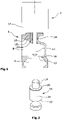
- FIG 1 shows a partially sectioned view of a control valve 2, which is designed here as an exhaust gas recirculation valve.
- the exhaust gas recirculation valve 2 shown here has a housing 4 which has an inlet opening 6 and an outlet opening 8 .
- a valve seat 10 is arranged between the inlet opening 6 and the outlet opening 8 and interacts with a valve closure body 12 in such a way that the inlet opening 6 can be separated from the outlet opening 8 or can also be fluidically connected to it.
- the valve closure body 12 is arranged in a known manner on a valve rod 14 , the valve rod 14 being movably mounted in a valve guide member 16 provided in the housing 4 . Furthermore, the valve rod 14 is operatively connected to an actuator device 17 shown schematically in such a way that the valve rod 14 can be moved in the axial direction.
- the actuator device 17 can be any type of drive device. In the present case, it is an electromotive actuator device 17, which is electrically connected in a known manner to a motor controller, not shown in detail. How even closer in the figure 2 is shown, at least one heating element 28 or 34 is provided in the valve guide element 16, which forms a heating device 22 together with electrical lines 18, 20. The electrical lines 18, 20 lead into the actuator device 17 and are connected there to the engine control unit, not shown in detail. As a result, a sticking, for example due to frozen liquids, can be remedied in a simple manner by heating before the valve is actuated.
- FIG 2 now shows a second embodiment of the valve guide member 16 in a schematic, perspective view figure 2 known contact plates 30, 32 and is connected to the electrical lines 18, 20.
- the PTC ceramic body 34 is heated in its entirety and thus leads to a release of the valve rod 14 if necessary
- the surface of the PTC ceramic body 34 running in the radial direction is covered by a suitable insulating material, which is not shown in any more detail here.
Landscapes
- Engineering & Computer Science (AREA)
- General Engineering & Computer Science (AREA)
- Mechanical Engineering (AREA)
- Chemical & Material Sciences (AREA)
- Combustion & Propulsion (AREA)
- Details Of Valves (AREA)
- Electrically Driven Valve-Operating Means (AREA)
Description
- Die Erfindung betrifft ein Regelventil zum Anbau an einen Kfz-Motor mit einem Gehäuse, das eine Einlass- und eine Auslassöffnung aufweist, zwischen denen ein Ventilsitz angeordnet ist, der derart mit einem Ventilverschlusskörper zusammenwirkt, dass eine fluidische Verbindung zwischen Einlass- und Auslassöffnung trenn- oder herstellbar ist, wobei der Ventilverschlusskörper sich an eine Ventilstange anschließt, die in einem Ventilführungsorgan im Gehäuse gelagert ist und durch eine Aktuatoreinrichtung bewegbar ist, wobei im Bereich des Ventilführungsorgans eine Heizvorrichtung mit mindestens einem Heizorgan vorgesehen ist.
- Derartige Regelventile sind aus dem Stand der Technik hinlänglich bekannt. Sie werden beispielsweise als Abgasrückführ- oder auch Sekundärluftventile im Kraftfahrzeug verbaut. Der Einbau im Kraftfahrzeug bedingt eine Funktion unter den unterschiedlichsten Umweltbedingungen. So können beispielsweise Schmutz- oder auch Abgaspartikel zu einem Verkleben bzw. Zusetzen der Ventilführung führen. Auch kann es bei besonders niedrigen Außentemperaturen zu einem Festfrieren der Ventilstange kommen. Um diese Nachteile wirkungsvoll zu verhindern, ist es aus der
FR 2 944 333 US 2003/0098066 A1 ist eine weitere Ausgestaltung eines Regelventils bekannt, welches eine zusätzliche, separate Heizvorrichtung aufweist, wobei die Heizvorrichtung die Ventilstange radial umgibt und sich aus einem Heizkörper sowie mehreren in dem Heizkörper angeordneten Heizelementen zusammensetzt. Derartige Ausführungsformen sind sehr aufwendig und daher teuer im konstruktiven Aufbau. - Aufgabe der Erfindung ist es daher, den oben genannten Nachteil zu vermeiden und ein Regelventil bereitzustellen, das einen einfachen und damit kostengünstigen sowie widerstandsfähigen Aufbau aufweist.
- Diese Aufgabe wird dadurch gelöst, dass das mindestens eine Heizorgan im Ventilführungsorgan vorgesehen ist, wobei als Heizorgan ein Feststoffheizelement in Form eines PTC-Heizelements vorgesehen ist, das das Ventilführungsorgan bildet. Hierdurch könnte ein Bauteil eingespart werden. Gleichzeitig wird das Auftreten von Koaxialfehlern minimiert. Auch kann ein direkterer Wärmeübergang zwischen Ventilstange und Ventilführungsorgan stattfinden, wodurch die Heizvorrichtung hinsichtlich der Heizleistung geringer ausgelegt werden kann.
- In einer besonders vorteilhaften Ausführungsform ist eine elektrische Kontaktierung an den Axialenden des Ventilführungsorgans jeweils mittels einer Kontaktplatte vorgesehen. Auf diese Weise ist eine besonders widerstandsfähige und sichere Konstruktion vorgesehen, die an die besonderen Randbedingungen im Kfz-Bereich angepasst ist
- Die Erfindung wird anhand einer Zeichnung näher erläutert, hierbei zeigt:
-
Figur 1 ein erfindungsgemäßes Regelventil in teilweise geschnittener Ansicht, und -
Figur 2 eine Ausführungsform eines Ventilführungsorgans. -
Figur 1 zeigt in teilweise geschnittener Ansicht ein Regelventil 2, das hier als Abgasrückführventil ausgeführt ist. Es sollte jedoch deutlich sein, dass die Erfindung nicht Abgasrückführventile beschränkt ist, sondern auch weitere Regelventile im Kfz-Bereich, wie Sekundärluftventil, Waste-Gate-Ventile, etc., umfasst. Das hier dargestellte Abgasrückführventil 2 weist ein Gehäuse 4 auf, das eine Einlassöffnung 6 und eine Auslassöffnung 8 besitzt. Zwischen der Einlassöffnung 6 und der Auslassöffnung 8 ist ein Ventilsitz 10 angeordnet, der derart mit einem Ventilverschlusskörper 12 zusammenwirkt, dass die Einlassöffnung 6 von der Auslassöffnung 8 getrennt werden kann oder auch fluidisch mit dieser verbunden werden kann. Der Ventilverschlusskörper 12 ist auf bekannte Weise an einer Ventilstange 14 angeordnet, wobei die Ventilstange 14 in einem im Gehäuse 4 vorgesehenen Ventilführungsorgan 16 beweglich gelagert ist. Des Weiteren ist die Ventilstange 14 mit einer schematisch dargestellten Aktuatoreinrichtung 17 derart wirkverbunden, dass die Ventilstange 14 in Axialrichtung bewegbar ist. Die Aktuatoreinrichtung 17 kann jegliche Art von Antriebseinrichtung sein. Im vorliegenden Fall handelt es sich um eine elektromotorische Aktuatoreinrichtung 17, die auf bekannte Weise mit einer nicht weiter dargestellten Motorsteuerung elektrisch verbunden ist. Wie noch näher in derFigur 2 dargestellt wird, ist in dem Ventilführungsorgan 16 mindestens ein Heizorgan 28 oder 34 vorgesehen, das zusammen mit elektrischen Leitungen 18, 20 eine Heizvorrichtung 22 bildet. Die elektrischen Leitungen 18, 20 führen in die Aktuatoreinrichtung 17 und sind dort mit dem nicht weiter dargestellten Motorsteuergerät verbunden. Hierdurch kann auf einfache Art und Weise ein Festsitzen, beispielsweise durch gefrorene Flüssigkeiten, durch eine Erwärmung vor der Ventilbetätigung behoben werden. -
Figur 2 zeigt nun in schematischer, perspektivischer Ansicht eine zweite Ausführungsform des Ventilführungsorgans 16. Hier besteht das Ventilführungsorgan 16 an sich aus einem PTC-Keramikkörper 34, der an seinen Axialenden durch die ausFigur 2 bekannten Kontaktplatten 30, 32 abgeschlossen und mit den elektrischen Leitungen 18, 20 verbunden ist. Der PTC-Keramikkörper 34 wird hierbei in seiner Gesamtheit erwärmt und führt somit im Bedarfsfall zu einer Lösung der Ventilstange 14. Auch die in Radialrichtung verlaufende Oberfläche des PTC-Keramikkörpers 34 wird durch ein geeignetes, hier nicht weiter dargestelltes Isolationsmaterial abgedeckt.
Claims (2)
- Regelventil (2) zum Anbau an einen Kfz-Motor mit einem Gehäuse (4), das eine Einlass (6)- und eine Auslassöffnung (8) aufweist, zwischen denen ein Ventilsitz angeordnet ist, der derart mit einem Ventilverschlusskörper zusammenwirkt, dass eine fluidische Verbindung (10) zwischen Einlass (6)- und Auslassöffnung (8) trenn- oder herstellbar ist, wobei der Ventilverschlusskörper (12) sich an eine Ventilstange (14) anschließt, die in einem Ventilführungsorgan (16) im Gehäuse (4) gelagert ist und durch eine Aktuatoreinrichtung (17) bewegbar ist, wobei im Bereich des Ventilführungsorgans (16) eine Heizvorrichtung (22) mit mindestens einem Heizorgan (28, 34) vorgesehen ist, dadurch gekennzeichnet, dass das mindestens eine Heizorgan (28, 34) im Ventilführungsorgan (16) vorgesehen ist, wobei als Heizorgan ein PTC-Heizelement (34) vorgesehen ist, das das Ventilführungsorgan (16) bildet.
- Regelventil nach Anspruch 1, dadurch gekennzeichnet, dass eine elektrische Kontaktierung an den Axialenden des Ventilführungsorgans (16) jeweils mittels einer Kontaktplatte (30, 32) vorgesehen ist.
Applications Claiming Priority (2)
| Application Number | Priority Date | Filing Date | Title |
|---|---|---|---|
| DE102014109273.2A DE102014109273A1 (de) | 2014-07-02 | 2014-07-02 | Regelventil zum Anbau an einen Kfz-Motor |
| PCT/EP2015/063664 WO2016000969A1 (de) | 2014-07-02 | 2015-06-18 | Regelventil zum anbau an einen kfz-motor |
Publications (2)
| Publication Number | Publication Date |
|---|---|
| EP3164591A1 EP3164591A1 (de) | 2017-05-10 |
| EP3164591B1 true EP3164591B1 (de) | 2022-11-02 |
Family
ID=53442783
Family Applications (1)
| Application Number | Title | Priority Date | Filing Date |
|---|---|---|---|
| EP15730485.8A Active EP3164591B1 (de) | 2014-07-02 | 2015-06-18 | Regelventil zum anbau an einen kfz-motor |
Country Status (3)
| Country | Link |
|---|---|
| EP (1) | EP3164591B1 (de) |
| DE (1) | DE102014109273A1 (de) |
| WO (1) | WO2016000969A1 (de) |
Families Citing this family (7)
| Publication number | Priority date | Publication date | Assignee | Title |
|---|---|---|---|---|
| EP3510835B1 (de) | 2016-09-08 | 2024-01-03 | Eichenauer Heizelemente GmbH & Co. KG | Ringförmiges heizelement |
| DE102017130673A1 (de) | 2017-12-20 | 2019-06-27 | Pierburg Gmbh | Regelventil für einen Verbrennungsmotor und Verfahren zur Regelung eines Regelventils |
| EP3924614B1 (de) | 2019-02-13 | 2024-04-17 | Pierburg GmbH | Ventilvorrichtung |
| JP7313169B2 (ja) * | 2019-03-19 | 2023-07-24 | 株式会社キッツエスシーティー | 真空ベローズホットバルブ |
| WO2021170250A1 (de) | 2020-02-28 | 2021-09-02 | Pierburg Gmbh | Abgasrückführsystem für eine verbrennungskraftmaschine sowie verfahren zur regelung eines derartigen abgasrückführsystems |
| CN111237100A (zh) * | 2020-03-09 | 2020-06-05 | 广西玉柴机器股份有限公司 | 一种egr阀和混合器加热控制方法及系统 |
| FR3155279A1 (fr) * | 2023-11-13 | 2025-05-16 | Bontaz Centre | Vanne de purge avec fonction de chauffage integree |
Family Cites Families (5)
| Publication number | Priority date | Publication date | Assignee | Title |
|---|---|---|---|---|
| ATE412111T1 (de) * | 2001-08-30 | 2008-11-15 | Cooper Standard Automotive Inc | Erwärmtes kurbelgehäuseentlüftungsventil und erwärmte schlauchanordnungen |
| JP3769495B2 (ja) * | 2001-11-26 | 2006-04-26 | Smc株式会社 | ヒーター付きポペット弁 |
| JP3778851B2 (ja) * | 2001-12-25 | 2006-05-24 | Smc株式会社 | ヒーター付きポペット弁 |
| FR2902470B1 (fr) * | 2006-06-19 | 2010-12-10 | Peugeot Citroen Automobiles Sa | Systeme de rechauffage du siege de soupape d'une vanne egr |
| FR2944333A1 (fr) | 2009-04-09 | 2010-10-15 | Peugeot Citroen Automobiles Sa | Vanne comprenant un element chauffant electrique |
-
2014
- 2014-07-02 DE DE102014109273.2A patent/DE102014109273A1/de not_active Withdrawn
-
2015
- 2015-06-18 WO PCT/EP2015/063664 patent/WO2016000969A1/de not_active Ceased
- 2015-06-18 EP EP15730485.8A patent/EP3164591B1/de active Active
Also Published As
| Publication number | Publication date |
|---|---|
| EP3164591A1 (de) | 2017-05-10 |
| DE102014109273A1 (de) | 2016-01-07 |
| WO2016000969A1 (de) | 2016-01-07 |
Similar Documents
| Publication | Publication Date | Title |
|---|---|---|
| EP3164591B1 (de) | Regelventil zum anbau an einen kfz-motor | |
| EP3140529B1 (de) | Abgasturbolader mit einem waste-gate-ventil | |
| EP3140531B1 (de) | Abgasturbolader mit einem waste-gate-ventil | |
| EP2997249B1 (de) | Abgasventilvorrichtung für eine verbrennungskraftmaschine | |
| WO2013156221A1 (de) | Abgasklappenvorrichtung für eine verbrennungskraftmaschine | |
| DE102017000936A1 (de) | Rückschlagventil mit Vereisungsschutz | |
| EP2616657B1 (de) | Kühlanordnung | |
| DE102006054041B3 (de) | Regelvorrichtung für eine Verbrennungskraftmaschine | |
| DE102015116834B4 (de) | Mehrpositionsaktuator | |
| EP3140530B1 (de) | Agbasturbolader mit einem waste-gate-ventil | |
| EP2942500A1 (de) | Abgaswärmetauscher mit bypassrohr | |
| EP2993337A1 (de) | Flugzeugtriebwerk mit mindestens einer vorrichtung zur entnahme von zapfluft | |
| DE102007025128A1 (de) | Ladeeinrichtung | |
| EP2395216B1 (de) | Klappenvorrichtung für eine Verbrennungskraftmaschine | |
| DE102015110261B4 (de) | Vorrichtung zum Stützen eines Ladedruckregelventilmoduls | |
| EP3221172B1 (de) | Luftzufuhreinstellvorrichtung für ein kraftfahrzeug | |
| EP3320202B1 (de) | Drei-wege-abgasrückführungs-ventilanordnung mit drei fluidöffnungen für eine abgasrückführung | |
| DE102011050263B4 (de) | Ventilvorrichtung für eine Verbrennungskraftmaschine | |
| DE102006043559B4 (de) | Drosselklappenvorrichtung für Hochtemperaturanwendungen in Verbrennungskraftmaschinen | |
| DE102013101792B4 (de) | Wärmepumpe | |
| EP3269959A1 (de) | Stellvorrichtung | |
| DE102014207671B4 (de) | Abgasturbolader mit einem Wastegate-Ventil | |
| DE102014004509B4 (de) | Regelvorrichtung | |
| WO2019121284A1 (de) | Regelventil für einen verbrennungsmotor und verfahren zur regelung eines regelventils | |
| EP3841320A1 (de) | Ventil zur steuerung von abgas oder frischluft in einer antriebseinheit eines kraftfahrzeuges oder generators |
Legal Events
| Date | Code | Title | Description |
|---|---|---|---|
| STAA | Information on the status of an ep patent application or granted ep patent |
Free format text: STATUS: THE INTERNATIONAL PUBLICATION HAS BEEN MADE |
|
| PUAI | Public reference made under article 153(3) epc to a published international application that has entered the european phase |
Free format text: ORIGINAL CODE: 0009012 |
|
| STAA | Information on the status of an ep patent application or granted ep patent |
Free format text: STATUS: REQUEST FOR EXAMINATION WAS MADE |
|
| 17P | Request for examination filed |
Effective date: 20161007 |
|
| AK | Designated contracting states |
Kind code of ref document: A1 Designated state(s): AL AT BE BG CH CY CZ DE DK EE ES FI FR GB GR HR HU IE IS IT LI LT LU LV MC MK MT NL NO PL PT RO RS SE SI SK SM TR |
|
| AX | Request for extension of the european patent |
Extension state: BA ME |
|
| DAV | Request for validation of the european patent (deleted) | ||
| DAX | Request for extension of the european patent (deleted) | ||
| STAA | Information on the status of an ep patent application or granted ep patent |
Free format text: STATUS: EXAMINATION IS IN PROGRESS |
|
| 17Q | First examination report despatched |
Effective date: 20201204 |
|
| GRAP | Despatch of communication of intention to grant a patent |
Free format text: ORIGINAL CODE: EPIDOSNIGR1 |
|
| STAA | Information on the status of an ep patent application or granted ep patent |
Free format text: STATUS: GRANT OF PATENT IS INTENDED |
|
| INTG | Intention to grant announced |
Effective date: 20220607 |
|
| GRAS | Grant fee paid |
Free format text: ORIGINAL CODE: EPIDOSNIGR3 |
|
| GRAA | (expected) grant |
Free format text: ORIGINAL CODE: 0009210 |
|
| STAA | Information on the status of an ep patent application or granted ep patent |
Free format text: STATUS: THE PATENT HAS BEEN GRANTED |
|
| AK | Designated contracting states |
Kind code of ref document: B1 Designated state(s): AL AT BE BG CH CY CZ DE DK EE ES FI FR GB GR HR HU IE IS IT LI LT LU LV MC MK MT NL NO PL PT RO RS SE SI SK SM TR |
|
| REG | Reference to a national code |
Ref country code: GB Ref legal event code: FG4D Free format text: NOT ENGLISH |
|
| REG | Reference to a national code |
Ref country code: CH Ref legal event code: EP Ref country code: AT Ref legal event code: REF Ref document number: 1528920 Country of ref document: AT Kind code of ref document: T Effective date: 20221115 |
|
| REG | Reference to a national code |
Ref country code: DE Ref legal event code: R096 Ref document number: 502015016138 Country of ref document: DE |
|
| REG | Reference to a national code |
Ref country code: IE Ref legal event code: FG4D Free format text: LANGUAGE OF EP DOCUMENT: GERMAN |
|
| REG | Reference to a national code |
Ref country code: LT Ref legal event code: MG9D |
|
| REG | Reference to a national code |
Ref country code: NL Ref legal event code: MP Effective date: 20221102 |
|
| PG25 | Lapsed in a contracting state [announced via postgrant information from national office to epo] |
Ref country code: SE Free format text: LAPSE BECAUSE OF FAILURE TO SUBMIT A TRANSLATION OF THE DESCRIPTION OR TO PAY THE FEE WITHIN THE PRESCRIBED TIME-LIMIT Effective date: 20221102 Ref country code: PT Free format text: LAPSE BECAUSE OF FAILURE TO SUBMIT A TRANSLATION OF THE DESCRIPTION OR TO PAY THE FEE WITHIN THE PRESCRIBED TIME-LIMIT Effective date: 20230302 Ref country code: NO Free format text: LAPSE BECAUSE OF FAILURE TO SUBMIT A TRANSLATION OF THE DESCRIPTION OR TO PAY THE FEE WITHIN THE PRESCRIBED TIME-LIMIT Effective date: 20230202 Ref country code: LT Free format text: LAPSE BECAUSE OF FAILURE TO SUBMIT A TRANSLATION OF THE DESCRIPTION OR TO PAY THE FEE WITHIN THE PRESCRIBED TIME-LIMIT Effective date: 20221102 Ref country code: FI Free format text: LAPSE BECAUSE OF FAILURE TO SUBMIT A TRANSLATION OF THE DESCRIPTION OR TO PAY THE FEE WITHIN THE PRESCRIBED TIME-LIMIT Effective date: 20221102 Ref country code: ES Free format text: LAPSE BECAUSE OF FAILURE TO SUBMIT A TRANSLATION OF THE DESCRIPTION OR TO PAY THE FEE WITHIN THE PRESCRIBED TIME-LIMIT Effective date: 20221102 |
|
| PG25 | Lapsed in a contracting state [announced via postgrant information from national office to epo] |
Ref country code: RS Free format text: LAPSE BECAUSE OF FAILURE TO SUBMIT A TRANSLATION OF THE DESCRIPTION OR TO PAY THE FEE WITHIN THE PRESCRIBED TIME-LIMIT Effective date: 20221102 Ref country code: PL Free format text: LAPSE BECAUSE OF FAILURE TO SUBMIT A TRANSLATION OF THE DESCRIPTION OR TO PAY THE FEE WITHIN THE PRESCRIBED TIME-LIMIT Effective date: 20221102 Ref country code: LV Free format text: LAPSE BECAUSE OF FAILURE TO SUBMIT A TRANSLATION OF THE DESCRIPTION OR TO PAY THE FEE WITHIN THE PRESCRIBED TIME-LIMIT Effective date: 20221102 Ref country code: IS Free format text: LAPSE BECAUSE OF FAILURE TO SUBMIT A TRANSLATION OF THE DESCRIPTION OR TO PAY THE FEE WITHIN THE PRESCRIBED TIME-LIMIT Effective date: 20230302 Ref country code: HR Free format text: LAPSE BECAUSE OF FAILURE TO SUBMIT A TRANSLATION OF THE DESCRIPTION OR TO PAY THE FEE WITHIN THE PRESCRIBED TIME-LIMIT Effective date: 20221102 Ref country code: GR Free format text: LAPSE BECAUSE OF FAILURE TO SUBMIT A TRANSLATION OF THE DESCRIPTION OR TO PAY THE FEE WITHIN THE PRESCRIBED TIME-LIMIT Effective date: 20230203 |
|
| PG25 | Lapsed in a contracting state [announced via postgrant information from national office to epo] |
Ref country code: NL Free format text: LAPSE BECAUSE OF FAILURE TO SUBMIT A TRANSLATION OF THE DESCRIPTION OR TO PAY THE FEE WITHIN THE PRESCRIBED TIME-LIMIT Effective date: 20221102 |
|
| PG25 | Lapsed in a contracting state [announced via postgrant information from national office to epo] |
Ref country code: SM Free format text: LAPSE BECAUSE OF FAILURE TO SUBMIT A TRANSLATION OF THE DESCRIPTION OR TO PAY THE FEE WITHIN THE PRESCRIBED TIME-LIMIT Effective date: 20221102 Ref country code: RO Free format text: LAPSE BECAUSE OF FAILURE TO SUBMIT A TRANSLATION OF THE DESCRIPTION OR TO PAY THE FEE WITHIN THE PRESCRIBED TIME-LIMIT Effective date: 20221102 Ref country code: EE Free format text: LAPSE BECAUSE OF FAILURE TO SUBMIT A TRANSLATION OF THE DESCRIPTION OR TO PAY THE FEE WITHIN THE PRESCRIBED TIME-LIMIT Effective date: 20221102 Ref country code: DK Free format text: LAPSE BECAUSE OF FAILURE TO SUBMIT A TRANSLATION OF THE DESCRIPTION OR TO PAY THE FEE WITHIN THE PRESCRIBED TIME-LIMIT Effective date: 20221102 Ref country code: CZ Free format text: LAPSE BECAUSE OF FAILURE TO SUBMIT A TRANSLATION OF THE DESCRIPTION OR TO PAY THE FEE WITHIN THE PRESCRIBED TIME-LIMIT Effective date: 20221102 |
|
| PGFP | Annual fee paid to national office [announced via postgrant information from national office to epo] |
Ref country code: DE Payment date: 20230620 Year of fee payment: 9 |
|
| REG | Reference to a national code |
Ref country code: DE Ref legal event code: R097 Ref document number: 502015016138 Country of ref document: DE |
|
| PG25 | Lapsed in a contracting state [announced via postgrant information from national office to epo] |
Ref country code: SK Free format text: LAPSE BECAUSE OF FAILURE TO SUBMIT A TRANSLATION OF THE DESCRIPTION OR TO PAY THE FEE WITHIN THE PRESCRIBED TIME-LIMIT Effective date: 20221102 Ref country code: AL Free format text: LAPSE BECAUSE OF FAILURE TO SUBMIT A TRANSLATION OF THE DESCRIPTION OR TO PAY THE FEE WITHIN THE PRESCRIBED TIME-LIMIT Effective date: 20221102 |
|
| PLBE | No opposition filed within time limit |
Free format text: ORIGINAL CODE: 0009261 |
|
| STAA | Information on the status of an ep patent application or granted ep patent |
Free format text: STATUS: NO OPPOSITION FILED WITHIN TIME LIMIT |
|
| 26N | No opposition filed |
Effective date: 20230803 |
|
| PG25 | Lapsed in a contracting state [announced via postgrant information from national office to epo] |
Ref country code: SI Free format text: LAPSE BECAUSE OF FAILURE TO SUBMIT A TRANSLATION OF THE DESCRIPTION OR TO PAY THE FEE WITHIN THE PRESCRIBED TIME-LIMIT Effective date: 20221102 |
|
| PG25 | Lapsed in a contracting state [announced via postgrant information from national office to epo] |
Ref country code: MC Free format text: LAPSE BECAUSE OF FAILURE TO SUBMIT A TRANSLATION OF THE DESCRIPTION OR TO PAY THE FEE WITHIN THE PRESCRIBED TIME-LIMIT Effective date: 20221102 |
|
| PG25 | Lapsed in a contracting state [announced via postgrant information from national office to epo] |
Ref country code: MC Free format text: LAPSE BECAUSE OF FAILURE TO SUBMIT A TRANSLATION OF THE DESCRIPTION OR TO PAY THE FEE WITHIN THE PRESCRIBED TIME-LIMIT Effective date: 20221102 |
|
| REG | Reference to a national code |
Ref country code: CH Ref legal event code: PL |
|
| REG | Reference to a national code |
Ref country code: BE Ref legal event code: MM Effective date: 20230630 |
|
| GBPC | Gb: european patent ceased through non-payment of renewal fee |
Effective date: 20230618 |
|
| PG25 | Lapsed in a contracting state [announced via postgrant information from national office to epo] |
Ref country code: LU Free format text: LAPSE BECAUSE OF NON-PAYMENT OF DUE FEES Effective date: 20230618 |
|
| REG | Reference to a national code |
Ref country code: IE Ref legal event code: MM4A |
|
| PG25 | Lapsed in a contracting state [announced via postgrant information from national office to epo] |
Ref country code: LU Free format text: LAPSE BECAUSE OF NON-PAYMENT OF DUE FEES Effective date: 20230618 |
|
| PG25 | Lapsed in a contracting state [announced via postgrant information from national office to epo] |
Ref country code: IE Free format text: LAPSE BECAUSE OF NON-PAYMENT OF DUE FEES Effective date: 20230618 |
|
| PG25 | Lapsed in a contracting state [announced via postgrant information from national office to epo] |
Ref country code: IE Free format text: LAPSE BECAUSE OF NON-PAYMENT OF DUE FEES Effective date: 20230618 Ref country code: CH Free format text: LAPSE BECAUSE OF NON-PAYMENT OF DUE FEES Effective date: 20230630 Ref country code: GB Free format text: LAPSE BECAUSE OF NON-PAYMENT OF DUE FEES Effective date: 20230618 |
|
| PG25 | Lapsed in a contracting state [announced via postgrant information from national office to epo] |
Ref country code: IT Free format text: LAPSE BECAUSE OF FAILURE TO SUBMIT A TRANSLATION OF THE DESCRIPTION OR TO PAY THE FEE WITHIN THE PRESCRIBED TIME-LIMIT Effective date: 20221102 Ref country code: FR Free format text: LAPSE BECAUSE OF NON-PAYMENT OF DUE FEES Effective date: 20230630 Ref country code: BE Free format text: LAPSE BECAUSE OF NON-PAYMENT OF DUE FEES Effective date: 20230630 |
|
| REG | Reference to a national code |
Ref country code: AT Ref legal event code: MM01 Ref document number: 1528920 Country of ref document: AT Kind code of ref document: T Effective date: 20230618 |
|
| PG25 | Lapsed in a contracting state [announced via postgrant information from national office to epo] |
Ref country code: AT Free format text: LAPSE BECAUSE OF NON-PAYMENT OF DUE FEES Effective date: 20230618 |
|
| PG25 | Lapsed in a contracting state [announced via postgrant information from national office to epo] |
Ref country code: AT Free format text: LAPSE BECAUSE OF NON-PAYMENT OF DUE FEES Effective date: 20230618 |
|
| PG25 | Lapsed in a contracting state [announced via postgrant information from national office to epo] |
Ref country code: BG Free format text: LAPSE BECAUSE OF FAILURE TO SUBMIT A TRANSLATION OF THE DESCRIPTION OR TO PAY THE FEE WITHIN THE PRESCRIBED TIME-LIMIT Effective date: 20221102 |
|
| PG25 | Lapsed in a contracting state [announced via postgrant information from national office to epo] |
Ref country code: BG Free format text: LAPSE BECAUSE OF FAILURE TO SUBMIT A TRANSLATION OF THE DESCRIPTION OR TO PAY THE FEE WITHIN THE PRESCRIBED TIME-LIMIT Effective date: 20221102 |
|
| PG25 | Lapsed in a contracting state [announced via postgrant information from national office to epo] |
Ref country code: CY Free format text: LAPSE BECAUSE OF FAILURE TO SUBMIT A TRANSLATION OF THE DESCRIPTION OR TO PAY THE FEE WITHIN THE PRESCRIBED TIME-LIMIT; INVALID AB INITIO Effective date: 20150618 |
|
| PG25 | Lapsed in a contracting state [announced via postgrant information from national office to epo] |
Ref country code: HU Free format text: LAPSE BECAUSE OF FAILURE TO SUBMIT A TRANSLATION OF THE DESCRIPTION OR TO PAY THE FEE WITHIN THE PRESCRIBED TIME-LIMIT; INVALID AB INITIO Effective date: 20150618 |
|
| PG25 | Lapsed in a contracting state [announced via postgrant information from national office to epo] |
Ref country code: TR Free format text: LAPSE BECAUSE OF FAILURE TO SUBMIT A TRANSLATION OF THE DESCRIPTION OR TO PAY THE FEE WITHIN THE PRESCRIBED TIME-LIMIT Effective date: 20221102 |
|
| REG | Reference to a national code |
Ref country code: DE Ref legal event code: R119 Ref document number: 502015016138 Country of ref document: DE |
|
| PG25 | Lapsed in a contracting state [announced via postgrant information from national office to epo] |
Ref country code: DE Free format text: LAPSE BECAUSE OF NON-PAYMENT OF DUE FEES Effective date: 20260101 |